汽车制动系统的日常维修保养毕业论文外文翻译
离合器汽车制动系统外文文献翻译、中英文翻译、外文翻译

3.1 ClutchThe engine produces the power to drive the vehicle. The drive line or drive train transfers the power of the engine to the wheels. The drive train consists of the parts from the back of the fl ywheel to the wheels. These parts include the clutch, the transmission, the drive shaft, and the final drive assembly.The clutch which includes the flywheel, clutch disc, pressure plate, springs, pressure plate cover and the linkage necessary to operate the clutch is a rotating mechanism between the engine and the transmission. It operates through friction which comes from contact between the parts. That is the reason why the clutch is called a friction mechanism. After engagement, the clutch must continue to transmit all engine torque to transmission depending on the friction without slippage. The clutch is also used to disengage the engine from the drive train whenever the gears in the transmission are being shifted from gear ratio to another.To start the engine or shift the gears, the driver has to depr ess the clutch pedal with the purpose of disengagement the transmission from the engine. At that time, the driven members connected to the transmission input shaft are either stationary or rotating at a speed that is slower of faster than the driving membe rs connected to engine crankshaft. There is no spring pressure on the clutch assembly parts. So there is no friction between the driving members and driven members. As the driver let’s loose the clutch pedal, spring pressure increase on the clutch parts. Friction between the parts also increases. The pressure exerted by the springs on the driven members is controlled by the driver through the clutch pedal and linkage. The positive engagement of the driving and driven members is made possible the friction be tween the surfaces of the members. When full spring pressure is applied, the speed of the driving and driven members should be the same. At themoment, the clutch must act as a coupling device and transmit all engine power to the transmission, without slipping.However, the transmission should be engaged to the engine graduall y in order to operate the car smoothly and minimize tensional shock on the drive train because an engine at idle just develop little power. Otherwise, the driving members are connecte d with the driven members too quickly and the engine would be stalled.The fl ywheel is a major part of the clutch. The flywheel mounts to the engine’s crankshaft and transmits engine torque to the clutch assembly. The flywheel, when coupled with the clutc h disc and pressure plate makes and breaks the flow of power the engine to the transmission.The flywheel provides a mounting location for the clutch assembly as well. When the clutch is applied, the fl ywheel transfers engine torque to the clutch disc. Because of its weight, the fl ywheel helps to smooth engine operation. The flywheel also has a large ring gear at its outer edge, which engages with a pinion gear on the starter motor during engine cranking.The clutch disc fits between the fl ywheel and the pressure plate. The clutch disc has a splinted hub that fits over splints on the transmission input shaft. A splinted hub has grooves that match splints on the shaft. These splints fit in the grooves. Thus, the two parts held together. However, back – and – forth movement of the disc on the shaft is possible. Attached to the input shaft, the disc turns at the speed of the shaft.The clutch pressure plate is generall y made of cast iron. It is round and about the same diameter as the clutch disc. One side of the pressure plate is machined smooth. This side will press the clutch disc facing are against the flywheel. The outer side has shapes to facilitate attachment of spring and release mechanism. The two primary t ypes of pressure plate assemblies are coil sp ring assembly and diaphragm spring.In a coil spring clutch the pressure plate is backed by a number of coil springs and housed with them in a pressed –steed cover bolted to the flywheel. The spring pushes against the cover. Neither the driven plate nor the pressure plate is connected rigidl y to the flywheel and both can move either towards it o away. When the clutch pedal is depressed a thrust pad riding on a carbon or ball thrust bearing is forced towards the flywheel. Levers pivoted so that they engage with the thrust pad at one end and the pressure plate tat the other end pull the pressure plate back against its springs. This releases pressure on the driven plate disconnecting the gearbox from the engine.Diaphragm spring pressure plate assemblies are widely used in most modern cars. The diaphragm spring is a single thin sheet of metal which yields when pressure is applied to it. When pressure is removed the metal spring back to its original shape. The center portion of the diaphragm spring is slit int o numerous fingers that act as release levers. When the clutch assembly rotates with the engine these weights are flung outwards by centrifugal plate and cause the levers to press against the pressure plate. During disengagement of the clutch the fingers are moved forward by the release bearing. The spring pivots over the fulcrum ring and its outer rim moves away from the flywheel. The retracting spring pulls the pressure plate away from the clutch plate thus disengaging the clutch.When engaged the release bearing and the fingers of the diaphragm spring move towards the transmission. As the diaphragm pivots over the pivot ring its outer rim forces the pressure plate against the clutch disc so that the clutch plate is engaged to flywheel.The advantages of a diaphragm t ype pressure plate assembl y are its compactness, lower weight, fewer moving parts, less effort to engage, reduces rotational imbalance by providing a balanced force around the pressure plate and less chances of clutch slippage.The clutch pedal is connected to the disengagement mechanismeither by a cable or, more commonly, by a hydraulic s ystem. Either way, pushing the pedal down operates the disengagement mechanism which puts pressure on the fingers of the clutch diaphragm via a release bearing and causes the diaphragm to release the clutch plate. With a hydraulic mechanism, the clutch pedal arm operates a piston in the clutch master cylinder. This forces hydraulic fluid through a pipe to the cutch release cylinder where another operates the c lutch disengagement mechanism by a cable.The other parts including the clutch fork, release bearing, bell –housing, bell housing cover, and pilot bushing are needed to couple and uncouple the transmission. The clutch fork, which connects to the linkage, actually operates the clutch. The release bearing fits between the clutch fork and the pressure plate assembly. The bell housing covers the clutch assembly. The bell housing cover fastens to the bottom of the bell housing. This removable cover allows a me chanic to inspect the clutch without removing the transmission and bell housing. A pilot bushing fits into the back of the crankshaft and holds the transmission input shaft.3.2 Brake SystemThe breaking system is the most important system in cars. If the brakes fail, the result can be disastrous. Brakes are actually energy conversion devices, which convert the kinetic energy (momentum) of the vehicle into thermal (heat). When stepping on the brakes, the driver commands a stopping force ten times as powerfu l as the force that puts the car in motion. The braking system can exert thousands of pounds of pressure on each of the four brakes.The brake s ystem is composed of the following basic components: the “master cylinder” which is located under the hood, and is directl yconnected to the brake pedal, converts driver foot’s mechanical pressure into hydraulic pressure. Steel “brake lines” and flexible “brake hoses” connect the master cylinder to the “slave cylinders” located at each wheel. Brake fluid, speciall y designed to work in extreme condition, fills the system. “Shoes” and “Pads” are pushed by the salve cylinders to contact the “drum” and “rotors” thus causing drag, which (hopefull y) slows the car.The typical brake system consists of disk brakes in front and either disk or drum brakes in the rear connected by a system of tubes and hoses that link the brake at each wheel to the master cylinder.Stepping on the brake pedal, a plunger is actually been pushing against in the master cylinder which forces hydr aulic oil (brake fluid) through a series of tubes and hoses to the braking unit at each wheel. Since hydraulic fluid (or any fluid for that matter) cannot be compressed, pushing fluid through a pipe is just like pushing a steel bar through pipe. Unlike a s teel bar, however, fluid can be directed through many twists and turns on its way to its destination, arriving with the exact same motion and pressure that it started with. It is very important that the fluid is pure liquid and that there is no air bubbles in it. Air can compress which causes sponginess to the pedal and severely reduced braking efficiency. If air is suspected, then the system must be bled to remove the air. There are “bleeder screws” at each wheel and caliper for this purpose.On disk brakes, the fluid from the master cylinder is forced into a caliper where it pressure against a piston. The piton, in-turn, squeezes two brake pads against the disk (rotor) which is attached to the wheel, forcing it to slow down or stop. This process is simila r to the wheel, causing the wheel to stop. In either case, the friction surface of the pads on a disk brake system, on the shoes on a drum brake convert the forward motion of the vehicle into heat. Heat is what causes the friction surfaces (lining) of the pads and shoes to eventually wear out andrequire replacement.Brake fluid is special oil that has specifics properties. It is designed to withstand cold temperatures without thickening as well as very high temperatures without boiling. (If the brake flui d should boil, it will cause you to have a spongy pedal and the car will be hard to stop).The brake fluid reservoir is on top of the master cylinder. Most cars today have a transparent reservoir so that you can see the level without opening the cover. Th e brake fluid lever will drop slightl y as the brake pads wear. This is a normal condition and no cause for concern. If the lever drops noticeabl y over a short period of time or goes down to about two thirds full, have your brakes checked as soon as possible. Keep the reservoir covered expect for the amount of time you need to fill it and never leave a can of brake fluid uncovered. Brake fluid must maintain a very high boiling point. Exposure to air will cause the fluid to absorb moisture which will lower th at boiling point.The brake fluid travels from the master cylinder to the wheels through a series of steel tubes and reinforced rubber hoses. Rubber hoses are onl y used in places that require flexibility, such as at the front wheels, which move up and dow n as well as steer. The rest of the system uses non-corrosive seamless steel tubing with special fittings at attachment points. If a steel line requires a repair, the best procedure is to replace the complete line. If this is nit practical, a line can be repaired using special splice fittings that are made for brake system repair. You must never use brass “compression” fittings or copper tubing repair a brake system. They are dangerous and illegal.3.2.1 Other Components in the Hydraulic System Proportioning Valve or Equalizer ValveThese valves are mounted between the master cylinder and the rear wheels. They are designed to adjust the pressure between the front and the rear brakes depending on how hard you are stopping. The shorter you stop, the mor e of the vehicle’s weight is transferred to the front wheels, in some cases, causing the rear to lift and the front to dive. These valves are designed to direct more pressure to the front and less pressure to the harder you stop. This minimizes the chance of premature lockup at the rear wheels.Pressure Differential ValveThis valve is usually mounted just below the master and is responsible for turning the brake warning light on when it detects a malfunction. It measures the pressure from the two sections of the master cylinder and compares them. Since it is mounted ahead of the proportioning or equalizer valve, the two pressures it detects should be equal. If it detects a difference, it means that there is probably a brake fluid leak somewhere in the syst em.3.1 离合器发动机产生动力来驱动汽车,它通过传动系把动力传递到车轮上,传动系包含从飞轮到车轮的所有零件。
汽车检测与维修专业汽车制动系统毕业论文外文文献翻译及原文
毕业设计(论文)外文文献翻译文献、资料中文题目:汽车制动系统文献、资料英文题目:文献、资料来源:文献、资料发表(出版)日期:院(部):专业:汽车检测与维修班级:姓名:学号:指导教师:翻译日期: 2017.02.14Automobile Brake SystemThe braking system is the most important system in cars. If the brakes fail, the result can be disastrous. Brakes are actually energy conversion devices, which convert the kinetic energy (momentum) of the vehicle into thermal energy (heat).When stepping on the brakes, the driver commands a stopping force ten times as powerful as the force that puts the car in motion. The braking system can exert thousands of pounds of pressure on each of the four brakes.Two complete independent braking systems are used on the car. They are the service brake and the parking brake.The service brake acts to slow, stop, or hold the vehicle during normal driving. They are foot-operated by the driver depressing and releasing the brake pedal. The primary purpose of the brake is to hold the vehicle stationary while it is unattended. The parking brake is mechanically operated by when a separate parking brake foot pedal or hand lever is set.The brake system is composed of the following basic components: the “master cylinder” which is located under the hood, and is directly connected to the brake pedal, converts driver foot’s mechanical pressure into hydraulic pressure. Steel “brake lines” and flexible “brake hoses” connect the master cylinder to the “slave cylinders” located at each wheel. Brake fluid, specially designed to work in extreme conditions, fills the system. “Shoes” and “pads” are pushed by the slave cy linders to contact the “drums” and “rotors” thus causing drag, which (hopefully) slows the car.The typical brake system consists of disk brakes in front and either disk or drum brakes in the rear connected by a system of tubes and hoses that link the brake at each wheel to the master cylinder (Figure).Basically, all car brakes are friction brakes. When the driver applies thebrake, the control device forces brake shoes, or pads, against the rotating brake drum or disks at wheel. Friction between the shoes or pads and the drums or disks then slows or stops the wheel so that the car is braked.In most modern brake systems (see Figure 15.1), there is a fluid-filled cylinder, called master cylinder, which contains two separate sections, there is a piston in each section and both pistons are connected to a brake pedal in the driver’s compartment. When the brake is pushed down, brake fluid is sent from the master cylinder to the wheels.At the wheels, the fluid pushes shoes, or pads, against revolving drums or disks. The friction between the stationary shoes, or pads, and the revolving drums or disks slows and stops them. This slows or stops the revolving wheels, which, in turn, slow or stop the car.The brake fluid reservoir is on top of the master cylinder. Most cars today have a transparent r reservoir so that you can see the level without opening the cover. The brake fluid level will drop slightly as the brake pads wear. This is a normal condition and no cause for concern. If the level drops noticeably over ashort period of time or goes down to about two thirds full, have your brakes checked as soon as possible. Keep the reservoir covered except for the amount of time you need to fill it and never leave a cam of brake fluid uncovered. Brake fluid must maintain a very high boiling point. Exposure to air will cause the fluid to absorb moisture which will lower that boiling point.The brake fluid travels from the master cylinder to the wheels through a series of steel tubes and reinforced rubber hoses. Rubber hoses are only used in places that require flexibility, such as at the front wheels, which move up and down as well as steer. The rest of the system uses non-corrosive seamless steel tubing with special fittings at all attachment points. If a steel line requires a repair, the best procedure is to replace the compete line. If this is not practical, a line can be repaired using special splice fittings that are made for brake system repair. You must never use copper tubing to repair a brake system. They are dangerous and illegal.Drum brakes, it consists of the brake drum, an expander, pull back springs, astationary back plate, two shoes with friction linings, and anchor pins. The stationary back plate is secured to the flange of the axle housing or to th e steering knuckle. The brake drum is mounted on the wheel hub. There is a clearance between the inner surface of the drum and the shoe lining. To apply brakes, the driver pushes pedal, the expander expands the shoes and presses them to the drum. Friction between the brake drum and the friction linings brakes the wheels and the vehicle stops. To release brakes, the driver release the pedal, the pull back spring retracts the shoes thus permitting free rotation of the wheels.Disk brakes, it has a metal disk instead of a drum. A flat shoe, or disk-brake pad, is located on each side of the disk. The shoes squeeze the rotatin g disk to stop the car. Fluid from the master cylinder forces the pistons to move in, toward the disk. This action pushes the friction pads tightly against the disk. The friction between the shoes and disk slows and stops it. This provides the braking action. Pistons are made of either plastic or metal. There are three general types of disk brakes. They are the floating-caliper type, the fixed-caliper type, and the sliding-caliper type. Floating-caliper and sliding-caliper disk brakes use a single piston. Fixed-caliper disk brakes have either two or four pistons.The brake system assemblies are actuated by mechanical, hydraulic or pneumatic devices. The mechanical leverage is used in the parking brakes fitted in all automobile. When the brake pedal is depressed, the rod pushes the piston of brake master cylinder which presses the fluid. The fluid flows through the pipelines to the power brake unit and then to the wheel cylinder. The fluid pressure expands the cylinder pistons thus pressing the shoes to the drum or disk. If the pedal is released, the piston returns to the initialposition, the pull back springs retract the shoes, the fluid is forced back to the master cylinder and braking ceases.The primary purpose of the parking brake is to hold the vehicle stationary while it is unattended. The parking brake is mechanically operated by the driver when a separate parking braking hand lever is set. The hand brake is normally used when the car has already stopped. A lever is pulled and the rear brakes are approached and locked in the “on” position. The car may now be left without fearof its rolling away. When the driver wants to move the car again, he must press a button before the lever can be released. The hand brake must also be able to stop the car in the event of the foot brake failing. For this reason, it is separate from the foot brake uses cable or rods instead of the hydraulic system.Anti-lock Brake SystemAnti-lock brake systems make braking safer and more convenient, Anti-lock brake systems modulate brake system hydraulic pressure to prevent the brakes from locking and the tires from skidding on slippery pavement or during a panic stop.Anti-lock brake systems have been used on aircraft for years, and some domestic car were offered with an early form of anti-lock braking in late 1990’s. Recently, several automakers have introduced more sophisticated anti-lock system. Investigations in Europe, where anti-lock brakin g systems have been available for a decade, have led one manufacture to state that the number of traffic accidents could be reduced by seven and a half percent if all cars had anti-lock brakes. So some sources predict that all cars will offer anti-lock brakes to improve the safety of the car.Anti-lock systems modulate brake application force several times per second to hold the tires at a controlled amount of slip; all systems accomplish this in basically the same way. One or more speed sensors generate alternating current signal whose frequency increases with the wheel rotational speed. An electronic control unit continuously monitors these signals and if the frequency of a signal drops too rapidly indicating that a wheel is about to lock, the control unit instructs a modulating device to reduce hydraulic pressure to the brake at the affected wheel. When sensor signals indicate the wheel is again rotating normally, the control unit allows increased hydraulic pressure to the brake. This release-apply cycle occurs several time per second to “pump” the brakes like a driver might but at a much faster rate.In addition to their basic operation, anti-lock systems have two other things in common. First, they do not operate until the brakes are applied with enough force to lock or nearly lock a wheel. At all other times, the system stands ready tofunction but does not interfere with normal braking. Second, if the anti-lock system fail in any way, the brakes continue to operate without anti-lock capability. A warning light on the instrument panel alerts the driver when a problem exists in the anti-lock system.The current Bosch component Anti-lock Braking System (ABSⅡ), is a second generation design wildly used by European automakers such as BWM, Mercedes-Benz and Porsche. ABSⅡ system consists of: four wheel speed sensor, electronic control unit and modulator assembly.A speed sensor is fitted at each wheel sends signals about wheel rotation to control unit. Each speed sensor consists of a sensor unit and a gear wheel. The front sensor mounts to the steering knuckle and its gear wheel is pressed onto the stub axle that rotates with the wheel. The rear sensor mounts the rear suspension member and its gear wheel is pressed onto the axle. The sensor itself is a winding with a magnetic core. The core creates a magnetic field around the winding, and as the teeth of the gear wheel move through this field, an alternating current is induced in the winding. The control unit monitors the rate o change in this frequency to determine impending brake lockup.The control unit’s function can be divided into three p arts: signal processing, logic and safety circuitry. The signal processing section is the converter that receives the alternating current signals form the speed sensors and converts them into digital form for the logic section. The logic section then analyzes the digitized signals to calculate any brake pressure changes needed. If impending lockup is sensed, the logic section sends commands to the modulator assembly.Modulator assemblyThe hydraulic modulator assembly regulates pressure to the wheel brakes when it receives commands from the control utuit. The modulator assembly can maintain or reduce pressure over the level it receives from the master cylinder, it also can never apply the brakes by itself. The modulator assembly consists of three high-speed electric solenoid valves, two fluid reservoirs and a turn delivery pump equipped with inlet and outlet check valves. The modulator electrical connector and controlling relays are concealed under a plastic cover of the。
汽车制动系统外文翻译

Automobile Brake SystemThe braking system is the most important system in cars. If the brakes fail, the result can be disastrous. Brakes are actually energy conversion devices, which convert the kinetic energy (momentum) of the vehicle into thermal energy (heat).When stepping on the brakes, the driver commands a stopping force ten times as powerful as the force that puts the car in motion. The braking system can exert thousands of pounds of pressure on each of the four brakes.Two complete independent braking systems are used on the car. They are the service brake and the parking brake.The service brake acts to slow, stop, or hold the vehicle during normal driving. They are foot-operated by the driver depressing and releasing the brake pedal. The primary purpose of the parking brake is to hold the vehicle stationary while it is unattended. The parking brake is mechanically operated by when a separate parking brake foot pedal or hand lever is set.The brake system is composed of the following basic components: the “master cylinder” which is located under the hood, and is directly connected to the brake pedal, converts driver foot’s mechanical pressure into hydraulic pressure. Steel “brake lines” and flexible “brake hoses” connect the master cylinder to the “slave cylinders” located at each wheel. Brake fluid, specially designed to work in extreme conditions, fills the system. “Shoes” and “pads” are pushed by the slave cylinders to contact the “drums” and “rotors” thus causing drag, which (hopefully) slows th e car.The typical brake system consists of disk brakes in front and either disk or drum brakes in the rear connected by a system of tubes and hoses that link the brake at each wheel to the master cylinder (Figure).Basically, all car brakes are friction brakes. When the driver applies the brake, the control device forces brake shoes, or pads, against the rotating brake drum or disks at wheel. Friction between the shoes or pads and the drums or disks then slows or stops the wheel so that the car is braked.In most modern brake systems (see Figure 15.1), there is afluid-filled cylinder, called master cylinder, which contains two separate sections, there is a piston in each section and both pistons are connected to a brake pedal in the driver’s compartment. W hen the brake is pushed down, brake fluid is sent from the master cylinder to the wheels.At the wheels, the fluid pushes shoes, or pads, against revolving drums or disks. The friction between the stationary shoes, or pads, and the revolving drums or disks slows and stops them. This slows or stops the revolving wheels, which, in turn, slow or stop the car.The brake fluid reservoir is on top of the master cylinder. Most cars today have a transparent reservoir so that you can see the level without opening the cover. The brake fluid level will drop slightly as the brake pads wear. This is a normal condition and no cause for concern. If the level drops noticeably over ashort period of time or goes down to about two thirds full, have your brakes checked as soon as possible. Keep the reservoir covered except for the amount of time you need to fill it and never leave a cam of brake fluid uncovered.Brake fluid must maintain a very high boiling point. Exposure to air will cause the fluid to absorb moisture which will lower that boiling point.The brake fluid travels from the master cylinder to the wheels through a series of steel tubes and reinforced rubber hoses. Rubber hoses are only used in places that require flexibility, such as at the front wheels, which move up and down as well as steer. The rest of the system uses non-corrosive seamless steel tubing with special fittings at all attachment points. If a steel line requires a repair, the best procedure is to replace the compete line. If this is not practical, a line can be repaired using special splice fittings that are made for brake system repair. You must never use copper tubing to repair a brake system. They are dangerous and illegal.Drum brakes, it consists of the brake drum, an expander, pull back springs, a stationary back plate, two shoes with friction linings, and anchor pins. The stationary back plate is secured to the flange of the axle housing or to the steering knuckle. The brake drum is mounted on the wheel hub. There is a clearance between the inner surface of the drum and the shoe lining. To apply brakes, the driver pushes pedal, the expander expands the shoes and presses them to the drum. Friction between the brake drum and the friction linings brakes the wheels and the vehicle stops. To release brakes, the driver release the pedal, the pull back spring retracts the shoes thus permitting free rotation of the wheels.Disk brakes, it has a metal disk instead of a drum. A flat shoe, or disk-brake pad, is located on each side of the disk. The shoes squeeze the rotatin g disk to stop the car. Fluid from the master cylinderforces the pistons to move in, toward the disk. This action pushes the friction pads tightly against the disk. The friction between the shoes and disk slows and stops it. This provides the braking action. Pistons are made of either plastic or metal. There are three general types of disk brakes. They are the floating-caliper type, the fixed-caliper type, and the sliding-caliper type. Floating-caliper and sliding-caliper disk brakes use a single piston. Fixed-caliper disk brakes have either two or four pistons.The brake system assemblies are actuated by mechanical, hydraulic or pneumatic devices. The mechanical leverage is used in the parking brakes fitted in all automobile. When the brake pedal is depressed, the rod pushes the piston of brake master cylinder which presses the fluid. The fluid flows through the pipelines to the power brake unit and then to the wheel cylinder. The fluid pressure expands the cylinder pistons thus pressing the shoes to the drum or disk. If the pedal is released, the piston returns to the initialposition, the pull back springs retract the shoes, the fluid is forced back to the master cylinder and braking ceases.The primary purpose of the parking brake is to hold the vehicle stationary while it is unattended. The parking brake is mechanically operated by the driver when a separate parking braking hand lever is set. The hand brake is normally used when the car has already stopped.A lever is pulled and the rear brakes are approached and locked in the “on” position. The car may now be left without fear of its rolling away. When the driver wants to move the car again, he must press a button before the lever can be released. The hand brake must also be able to stop the car in the event of the foot brake failing.For this reason, it is separate from the foot brake uses cable or rods instead of the hydraulic system.Anti-lock Brake SystemAnti-lock brake systems make braking safer and more convenient, Anti-lock brake systems modulate brake system hydraulic pressure to prevent the brakes from locking and the tires from skidding on slippery pavement or during a panic stop.Anti-lock brake systems have been used on aircraft for years, and some domestic car were offered with an early form of anti-lock braking in late 1990’s. Recently, several automakers have introduced more sophisticated anti-lock system. Investigations in Europe, where anti-lock brakin g systems have been available for a decade, have led one manufacture to state that the number of traffic accidents could be reduced by seven and a half percent if all cars had anti-lock brakes. So some sources predict that all cars will offer anti-lock brakes to improve the safety of the car.Anti-lock systems modulate brake application force several times per second to hold the tires at a controlled amount of slip; all systems accomplish this in basically the same way. One or more speed sensors generate alternating current signal whose frequency increases with the wheel rotational speed. An electronic control unit continuously monitors these signals and if the frequency of a signal drops too rapidly indicating that a wheel is about to lock, the control unit instructs a modulating device to reduce hydraulic pressure to the brake at the affected wheel. When sensor signals indicate the wheel is again rotating normally, the control unit allows increased hydraulic pressure to the brake. This release-apply cycle occursseveral time per second to “pump” the brakes like a driver mig ht but at a much faster rate.In addition to their basic operation, anti-lock systems have two other things in common. First, they do not operate until the brakes are applied with enough force to lock or nearly lock a wheel. At all other times, the system stands ready to function but does not interfere with normal braking. Second, if the anti-lock system fail in any way, the brakes continue to operate without anti-lock capability. A warning light on the instrument panel alerts the driver when a problem exists in the anti-lock system.The current Bosch component Anti-lock Braking System (ABSⅡ), is a second generation design wildly used by European automakers such as BWM, Mercedes-Benz and Porsche. ABSⅡ system consists of : four wheel speed sensor, electronic control unit and modulator assembly.A speed sensor is fitted at each wheel sends signals about wheel rotation to control unit. Each speed sensor consists of a sensor unit and a gear wheel. The front sensor mounts to the steering knuckle and its gear wheel is pressed onto the stub axle that rotates with the wheel. The rear sensor mounts the rear suspension member and its gear wheel is pressed onto the axle. The sensor itself is a winding with a magnetic core. The core creates a magnetic field around the winding, and as the teeth of the gear wheel move through this field, an alternating current is induced in the winding. The control unit monitors the rate o change in this frequency to determine impending brake lockup.The control unit’s function can be divided into three parts: signal processing, logic and safety circuitry. The signal processing sectionis the converter that receives the alternating current signals form the speed sensors and converts them into digital form for the logic section. The logic section then analyzes the digitized signals to calculate any brake pressure changes needed. If impending lockup is sensed, the logic section sends commands to the modulator assembly.Modulator assemblyThe hydraulic modulator assembly regulates pressure to the wheel brakes when it receives commands from the control utuit. The modulator assembly can maintain or reduce pressure over the level it receives from the master cylinder, it also can never apply the brakes by itself. The modulator assembly consists of three high-speed electric solenoid valves, two fluid reservoirs and a turn delivery pump equipped with inlet and outlet check valves. The modulator electrical connector and controlling relays are concealed under a plastic cover of the assembly.Each front wheel is served by electric solenoid valve modulated independently by the control unit. The rear brakes are served by a single solenoid valve and modulated together using the select-low principle. During anti-braking system operation, the control unit cycles the solenoid valves to either hold or release pressure the brake lines. When pressure is released from the brake lines during anti-braking operation, it is routed to a fluid reservoir. There is one reservoir for the front brake circuit. The reservoirs arelow-pressure accumulators that store fluid under slight spring pressure until the return delivery pump can return the fluid through the brake lines to the master cylinder.汽车制动系统制动系统是汽车上最重要的系统。
车辆工程外文翻译--日常汽车保养
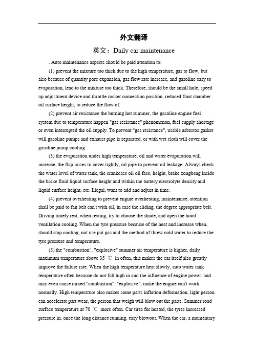
外文翻译英文:Daily car maintenance. Auto maintenance aspects should be paid attention to:(1) prevent the mixture too thick due to the high temperature, gas to flow, but also because of quantity pore expansion, gas flow rate increase, and gasoline easy to evaporation, lead to the mixture too thick. Therefore, should be the small hole, speed up adjustment device and throttle rocker connection position, reduced float chamber oil surface height, to reduce the flow of.(2) prevent air resistance the burning hot summer, the gasoline engine fuel system due to temperature happen "gas resistance" phenomenon, fuel supply shortage or even interrupted the oil supply. To prevent "gas resistance", usable asbestos gasket will gasoline pumps and exhaust pipe is separated, or with wet cloth will cover the gasoline pump cooling.(3) the evaporation under high temperature, oil and water evaporation will increase, the flap raises to cover tightly, oil pipe to prevent oil leakage; Always check the water level of water tank, the crankcase oil oil face, height, brake zongbeng inside the brake fluid liquid surface height and within the battery electrolyte density and liquid surface height, etc. Illegal, want to add and adjust in time.(4) prevent overheating to prevent engine overheating, maintenance, attention shall be paid to fan belt can't with oil, in case the sliding, the degree appropriate belt. Driving timely rest, when resting, try to choose the shade, and open the hood ventilation cooling. When the tyre pressure because of the heat and increase when, should stop cooling, not use put gas and the method of threw cold water to reduce the tyre pressure and temperature.(5) the "combustion", "explosive" summer air temperature is higher, daily maximum temperature above 35 ℃in often, this makes the car itself also greatly improve the failure rate. When the high temperature heat slowly, auto water tank temperature often because do not fall high in and the influence of engine power, and may even cause mixed "combustion", "explosive", make the engine can't work normally. High temperature also makes some parts inflation deformation, light person can accelerate part wear, the person that weigh will blow out the parts. Summer road surface temperature at 70 ℃more often. Car tires for heated, the tyres increased pressure in, once the long distance running, easy blowout. When the car, a momentarybreaks down, it can also cause traffic accident.(6) the bad lubrication oil easily heated goes lean, oxidation resistance becomes poor, easy metamorphism, even cause the tile burning failure holding shaft. Therefore, should the crankcase and gear box with the oil changed into summer, often check the number of oil, lubricating oil, and in time to change.(7) the car paint the car paint him as insolate of skin, to bright and clean and bright beautiful, just cute. Although it seems to have no life, but it is also afraid of sun, long-term exposure willFaJiu, corrugate.The summer will often clean the car, in order to prevent the rain to car lacquer cause acid corrosion, also had better not on the street and wash your car, the repeated use of water sediment will scratch the car paint secretly. Next summer and the car that do more decontamination processing, summer bus is easy to splash on the viscosity substances, air temperature is exorbitant, will also be full of asphalt splash body. In that case, to do as soon as possible beauty treatment, using special detergents remove dirt, serious, want to undertake polishing processing. Some dirt if not handled in a timely manner, with all kinds of methods to remove not to drop, can only local polishing paint, paint again.The summer will pay more attention to the engine work environment, made timely cleaning work, if the engine external pollution too thick, it will affect the machine heat dissipation, give all sorts of machine fault buried hidden trouble. Summer should also be to paint on certain preventive protection, such as wax, glazing. Auto accessories part of the nursing in the summer also more important, such as the wheel hub, electroplating parts to timely derusting, clean, bumper, tires and other rubber and plastic parts to do add black glazing, anti-aging treatment.Common beauty protection- -wash the car wax, although some effect, but not for good. Because any waxes contain silicon ingredients, and ultraviolet ray will rust the car paint, leaving little black patches. And the car wax grinding particles, will be in the light of the car paint leave way way fine marks. Car wax itself up less than increase hardness, resistance ultraviolet function, will soon loss due to the temperature too high. Therefore, When the car parking shall be in the shade.The six main engine maintenance1. Use proper quality level of the lubricating oilThe engine should be for gasoline into the exhaust system according to additional devices and the using conditions choose SD-SF petrol engine oil level; Thediesel engine according to the mechanical load selection CB-CD level diesel engine oil, choose standard to not under production factory regulations shall prevail.2. Change regularly oil and filterAny quality level of the lubricating oil in use process of oil will change. To a certain mileage after, performance deterioration would bring a variety of problems to the engine. In order to avoid of failure, should combine conditions of use regular oil, and that the amount of oil moderate (generally in oil rod cap of good). The oil from the pores through the filter when the solid particles and viscous oil content stored up in filter. Such as filter jams, oil, not through the filter, will burst filter or turn on the relief valve, from bypass valve through, still the dirt back to lubrication part, make the engine wear, the internal worsening pollution.3. Keep the crankcase ventilationNow most of the gasoline engine are equipped with PCV valves (the crankcase forced ventilation device) prompted the engine take a breath, but channeling the pollutant in gas will "deposition in the valve, PCV around the valve plug. If possible PCV valves jams then pollution reverse flow gas air filter, pollution people filter core, make filtering ability, reduce inhaled mixture of dirty, caused the pollution, more crankcase to increase fuel consumption, engine wear more, even engine damage. Therefore, must be maintained regularly PCV, PCV valves clear around the pollutants.4. Regular cleaning the crankcaseThe engine running process, the combustion chamber not burning gas, high pressure water and sulfur acid, and of nitrogen oxide piston and cylinder wall after the clearance between into the crankcase, with parts wear produced metal powder mix together, form sludge. Quantity in oil suspended for a little time, large amount of precipitation from oil, blocked filter and the oil hole, cause the engine lubrication difficulties, caused by wear. In addition, the oil in the high temperature oxidation film and generates carbon bond on the piston, make the engine oil consumption, increase power decrease, serious when the rings card died and pull cylinder. Therefore, regular cleaning the crankcase and maintain engine internal clean.5. Regular cleaning fuel systemFuel in through the oil for the process of burning to the combustion chamber, inevitably will form the colloid and carbon, in oil,, carburetor, nozzles and deposited in the combustion chamber, interfering with the fuel flow, disrupt the normal air-fuelratio make fuel atomization bad, cause the engine out of shaking, blasting vibration, the idle instability, poor acceleration performance problem. Regular cleaning fuel oil system, control the generation of carbon, can always be the best to make the engine.6. Maintenance regularly water tankEngine water tank rust, scale is the most common problems. The grunge and scale can limit the cooling fluid in the cooling system, the flow, reduce the cooling effect, cause the engine overheat, even cause the engine damage. The cooling liquid oxygen also forms acidity material, corrosion water tank the metal components, causing the water tank damage and leakage. Regularly use the water tank cleaner water tank, remove the rust and scale, can not only ensure normal engine work, and extend the life of the whole water tank and the engine.中文:日常汽车保养汽车日常保养方面应该注意:(1)防混合气过浓由于气温高,汽油容易流动,还因量孔膨胀,使汽油流量增加,且汽油容易蒸发,导致混合气过浓。
关于汽车制动系统英文作文

关于汽车制动系统英文作文英文:When it comes to the safety of a vehicle, the braking system is one of the most crucial components. The braking system is responsible for slowing down or stopping a vehicle when necessary. There are several types of braking systems, including disc brakes, drum brakes, and anti-lock braking systems (ABS).Disc brakes are the most common type of braking system used in modern vehicles. They consist of a rotor, caliper, and brake pads. When the brake pedal is pressed, thecaliper squeezes the brake pads against the rotor, creating friction and slowing down the vehicle. Disc brakes are known for their reliability and durability.Drum brakes, on the other hand, are becoming less common in modern vehicles. They consist of a brake drum, brake shoes, and a wheel cylinder. When the brake pedal ispressed, the brake shoes are pushed against the brake drum, creating friction and slowing down the vehicle. Drum brakes are known for their simplicity and low cost.ABS is a more advanced type of braking system that prevents the wheels from locking up during braking. This helps the driver maintain control of the vehicle and reduces the risk of skidding. ABS works by monitoring the speed of each wheel and adjusting the braking force accordingly.In addition to the types of braking systems, it's also important to regularly maintain and inspect the braking system. This includes checking the brake pads and rotorsfor wear, ensuring proper brake fluid levels, and checking for any leaks or damage.Overall, the braking system is a vital component of a vehicle's safety. It's important to understand thedifferent types of braking systems and how to properly maintain them to ensure a safe driving experience.中文:谈到车辆安全,制动系统是其中最关键的组成部分之一。
(完整版)汽车制动系统英文文献及翻译)

Automobile Brake SystemThe braking system is the most important system in cars. If the brakes fail, the result can be disastrous. Brakes are actually energy conversion devices, which convert the kinetic energy (momentum) of the vehicle into thermal energy (heat).When stepping on the brakes, the driver commands a stopping force ten times as powerful as the force that puts the car in motion. The braking system can exert thousands of pounds of pressure on each of the four brakes.Two complete independent braking systems are used on the car. They are the service brake and the parking brake.The service brake acts to slow, stop, or hold the vehicle during normal driving. They are foot-operated by the driver depressing and releasing the brake pedal. The primary purpose of the brake is to hold the vehicle stationary while it is unattended. The parking brake is mechanically operated by when a separate parking brake foot pedal or hand lever is set.The brake system is composed of the following basic components: t he “master cylinder” which is located under the hood, and is directly connected to the brake pedal, converts driver foot’s mechanical pressure into hydraulic pressure. Steel “brake lines” and flexible “brake hoses” connect the master cylinder to the “slave cylinders” located at each wheel. Brake fluid, specially designed to work in extreme conditions, fills the system. “Shoes” and “pads” are pushed by the slave cylinders to contact the “drums” and “rotors” thus causing drag, which (hopefully) slows the car.The typical brake system consists of disk brakes in front and either disk or drum brakes in the rear connected by a system of tubes and hoses that link the brake at each wheel to the master cylinder (Figure).Basically, all car brakes are friction brakes. When the driver applies the brake, the control device forces brake shoes, or pads, against the rotating brake drum or disks at wheel. Friction between the shoes or pads and the drums or disks then slows or stops the wheel so that the car is braked.In most modern brake systems (see Figure 15.1), there is a fluid-filled cylinder, called master cylinder, which contains two separate sections, there is a piston in each section and both pistons are connected to a brake pedal in the driver’s compartment. When th e brake is pushed down, brake fluid is sent from the master cylinder to the wheels.At the wheels, the fluid pushes shoes, or pads, against revolving drums or disks. The friction between the stationary shoes, or pads, and the revolving drums or disks slows and stops them. This slows or stops the revolving wheels, which, in turn, slow or stop the car.The brake fluid reservoir is on top of the master cylinder. Most cars today have a transparent r reservoir so that you can see the level without opening the cover. The brake fluid level will drop slightly as the brake pads wear. This is a normal condition and no cause for concern. If the level drops noticeably over ashort period of time or goes down to about two thirds full, have your brakes checked as soon as possible. Keep the reservoir covered except for the amount of time you need to fill it and never leave a cam of brake fluid uncovered. Brake fluid must maintain a very high boiling point. Exposure to air will cause the fluid to absorb moisture which will lower that boiling point.The brake fluid travels from the master cylinder to the wheels through a series of steel tubes and reinforced rubber hoses. Rubber hoses are only used in places that require flexibility, such asat the front wheels, which move up and down as well as steer. The rest of the system uses non-corrosive seamless steel tubing with special fittings at all attachment points. If a steel line requires a repair, the best procedure is to replace the compete line. If this is not practical, a line can be repaired using special splice fittings that are made for brake system repair. You must never use copper tubing to repair a brake system. They are dangerous and illegal.Drum brakes, it consists of the brake drum, an expander, pull back springs, a stationary back plate, two shoes with friction linings, and anchor pins. The stationary back plate is secured to the flange of the axle housing or to the steering knuckle. The brake drum is mounted on the wheel hub. There is a clearance between the inner surface of the drum and the shoe lining. To apply brakes, the driver pushes pedal, the expander expands the shoes and presses them to the drum. Friction between the brake drum and the friction linings brakes the wheels and the vehicle stops. To release brakes, the driver release the pedal, the pull back spring retracts the shoes thus permitting free rotation of the wheels.Disk brakes, it has a metal disk instead of a drum. A flat shoe, or disk-brake pad, is located on each side of the disk. The shoes squeeze the rotatin g disk to stop the car. Fluid from the master cylinder forces the pistons to move in, toward the disk. This action pushes the friction pads tightly against the disk. The friction between the shoes and disk slows and stops it. This provides the braking action. Pistons are made of either plastic or metal. There are three general types of disk brakes. They are the floating-caliper type, the fixed-caliper type, and the sliding-caliper type. Floating-caliper and sliding-caliper disk brakes use a single piston. Fixed-caliper disk brakes have either two or four pistons.The brake system assemblies are actuated by mechanical, hydraulic or pneumatic devices. The mechanical leverage is used in the parking brakes fitted in all automobile. When the brake pedal is depressed, the rod pushes the piston of brake master cylinder which presses the fluid. The fluid flows through the pipelines to the power brake unit and then to the wheel cylinder. The fluid pressure expands the cylinder pistons thus pressing the shoes to the drum or disk. If the pedal is released, the piston returns to the initialposition, the pull back springs retract the shoes, the fluid is forced back to the master cylinder and braking ceases.The primary purpose of the parking brake is to hold the vehicle stationary while it is unattended. The parking brake is mechanically operated by the driver when a separate parking braking hand lever is set. The hand brake is normally used when the car has already stopped. A lever is pulled and t he rear brakes are approached and locked in the “on” position. The car may now be left without fear of its rolling away. When the driver wants to move the car again, he must press a button before the lever can be released. The hand brake must also be able to stop the car in the event of the foot brake failing. For this reason, it is separate from the foot brake uses cable or rods instead of the hydraulic system.Anti-lock Brake SystemAnti-lock brake systems make braking safer and more convenient, Anti-lock brake systems modulate brake system hydraulic pressure to prevent the brakes from locking and the tires from skidding on slippery pavement or during a panic stop.Anti-lock brake systems have been used on aircraft for years, and some domestic car were offered with an early form of anti-lock braking in late 1990’s. Recently, several automakers have introduced more sophisticated anti-lock system. Investigations in Europe, where anti-lock brakin g systems have been available for a decade, have led one manufacture to state that the number oftraffic accidents could be reduced by seven and a half percent if all cars had anti-lock brakes. So some sources predict that all cars will offer anti-lock brakes to improve the safety of the car.Anti-lock systems modulate brake application force several times per second to hold the tires at a controlled amount of slip; all systems accomplish this in basically the same way. One or more speed sensors generate alternating current signal whose frequency increases with the wheel rotational speed. An electronic control unit continuously monitors these signals and if the frequency of a signal drops too rapidly indicating that a wheel is about to lock, the control unit instructs a modulating device to reduce hydraulic pressure to the brake at the affected wheel. When sensor signals indicate the wheel is again rotating normally, the control unit allows increased hydraulic pressure to the brake. This release-apply cycle occurs several time per second to “pump” the brakes like a dr iver might but at a much faster rate.In addition to their basic operation, anti-lock systems have two other things in common. First, they do not operate until the brakes are applied with enough force to lock or nearly lock a wheel. At all other times, the system stands ready to function but does not interfere with normal braking. Second, if the anti-lock system fail in any way, the brakes continue to operate without anti-lock capability. A warning light on the instrument panel alerts the driver when a problem exists in the anti-lock system.The current Bosch component Anti-lock Braking System (ABSⅡ), is a second generation design wildly used by European automakers such as BWM, Mercedes-Benz and Porsche. ABSⅡsystem consists of : four wheel speed sensor, electronic control unit and modulator assembly.A speed sensor is fitted at each wheel sends signals about wheel rotation to control unit. Each speed sensor consists of a sensor unit and a gear wheel. The front sensor mounts to the steering knuckle and its gear wheel is pressed onto the stub axle that rotates with the wheel. The rear sensor mounts the rear suspension member and its gear wheel is pressed onto the axle. The sensor itself is a winding with a magnetic core. The core creates a magnetic field around the winding, and as the teeth of the gear wheel move through this field, an alternating current is induced in the winding. The control unit monitors the rate o change in this frequency to determine impending brake lockup.The control unit’s functi on can be divided into three parts: signal processing, logic and safety circuitry. The signal processing section is the converter that receives the alternating current signals form the speed sensors and converts them into digital form for the logic section. The logic section then analyzes the digitized signals to calculate any brake pressure changes needed. If impending lockup is sensed, the logic section sends commands to the modulator assembly.Modulator assemblyThe hydraulic modulator assembly regulates pressure to the wheel brakes when it receives commands from the control utuit. The modulator assembly can maintain or reduce pressure over the level it receives from the master cylinder, it also can never apply the brakes by itself. The modulator assembly consists of three high-speed electric solenoid valves, two fluid reservoirs and a turn delivery pump equipped with inlet and outlet check valves. The modulator electrical connector and controlling relays are concealed under a plastic cover of the assembly.Each front wheel is served by electric solenoid valve modulated independently by the control unit. The rear brakes are served by a single solenoid valve and modulated together using the select-low principle. During anti-braking system operation, the control unit cycles the solenoid valves to either hold or release pressure the brake lines. When pressure is released from the brakelines during anti-braking operation, it is routed to a fluid reservoir. There is one reservoir for the front brake circuit. The reservoirs are low-pressure accumulators that store fluid under slight spring pressure until the return delivery pump can return the fluid through the brake lines to the master cylinder.汽车制动系统制动系统是汽车中最重要的系统。
外文翻译---汽车制动系统
附录1外文翻译Automobile Brake SystemThe braking system is the most important system in cars. If the brakes fail, the result can be disastrous. Brakes are actually energy conversion devices, which convert the kinetic energy (momentum) of the vehicle into thermal energy (heat).When stepping on the brakes, the driver commands a stopping force ten times as powerful as the force that puts the car in motion. The braking system can exert thousands of pounds of pressure on each of the four brakes.Two complete independent braking systems are used on the car. They are the service brake and the parking brake.The service brake acts to slow, stop, or hold the vehicle during normal driving. They are foot-operated by the driver depressing and releasing the brake pedal. The primary purpose of the brake is to hold the vehicle stationary while it is unattended. The parking brake is mechanically operated by when a separate parking brake footpedal or hand lever is set.The brake system is composed of the following basic components: the “master cylinder” which is located under the hood, and is directly connected to the brake pedal, converts driver foot’s mechanical pressure into hydraulic pressure. Steel “brake lines” and flexible “brake hoses” connect the master cylinder to the “slave cylinders” located at each wheel. Brake fluid, specially designed to work in extreme conditions, fills thesystem. “Shoes” and “pads” are pushed by the slave cylinders to contact the “drums” and “rotors” thus causing drag, which (hopefully) s lows the car.The typical brake system consists of disk brakes in front and either disk or drum brakes in the rear connected by a system of tubes and hoses that link the brake at each wheel to the master cylinder (Figure).Basically, all car brakes are friction brakes. When the driver applies the brake, the control device forces brake shoes, or pads, against the rotating brake drum or disks at wheel. Friction between the shoes or pads and the drums or disks then slows or stops the wheel so that the car is braked.In most modern brake systems (see Figure 15.1), there is a fluid-filled cylinder, called master cylinder, which contains two separate sections, there is a piston in each section and both pistons are connected to a brake pedal in the driver’s compartment. When the brake is pushed down, brake fluid is sent from the master cylinder to the wheels. At the wheels, the fluid pushes shoes, or pads, against revolving drums or disks. The friction between the stationary shoes, or pads, and the revolving drums or disks slows and stops them. This slows or stops the revolving wheels, which, in turn, slow or stop the car.The brake fluid reservoir is on top of the master cylinder. Most cars today have a transparent r reservoir so that you can see the level without opening the cover. The brake fluid level will drop slightly as the brake pads wear. This is a normal condition and no cause for concern. If the level drops noticeably over a short period of time or goes down to about two thirds full, have your brakes checked as soon as possible. Keep the reservoir covered except for the amount of time you need to fill it and never leave a cam of brake fluid uncovered. Brake fluid must maintain a very high boiling point. Exposure to air will cause the fluid to absorb moisture which will lower that boiling point.The brake fluid travels from the master cylinder to the wheels through a series of steel tubes and reinforced rubber hoses. Rubber hoses are only used in places that require flexibility, such as at the front wheels, which move up and down as well as steer. The rest of the system uses non-corrosive seamless steel tubing with special fittings at all attachment points. If a steel line requires a repair, the best procedure is to replace the compete line. If this is not practical, a line can be repaired using special splice fittings that are made for brake system repair. You must never use copper tubing to repair a brake system. They are dangerous and illegal.Drum brakes, it consists of the brake drum, an expander, pull back springs, a stationary back plate, two shoes with friction linings, and anchor pins. The stationary back plate is secured to the flange of the axle housing or to the steering knuckle. The brake drum is mounted on the wheel hub. There is a clearance between the inner surface of the drum and the shoe lining. To apply brakes, the driver pushes pedal, theexpander expands the shoes and presses them to the drum. Friction between the brake drum and the friction linings brakes the wheels and the vehicle stops. To release brakes, the driver release the pedal, the pull back spring retracts the shoes thus permitting free rotation of the wheels.Disk brakes, it has a metal disk instead of a drum. A flat shoe, or disk-brake pad, is located on each side of the disk. The shoes squeeze the rotating disk to stop the car. Fluid from the master cylinder forces the pistons to move in, toward the disk. This action pushes the friction pads tightly against the disk. The friction between the shoes and disk slows and stops it. This provides the braking action. Pistons are made of either plastic or metal. There are three general types of disk brakes. They are the floating-caliper type, the fixed-caliper type, and the sliding-caliper type. Floating-caliper and sliding-caliper disk brakes use a single piston. Fixed-caliper disk brakes have either two or four pistons.The brake system assemblies are actuated by mechanical, hydraulic or pneumatic devices. The mechanical leverage is used in the parking brakes fitted in all automobile. When the brake pedal is depressed, the rod pushes the piston of brake master cylinder which presses the fluid. The fluid flows through the pipelines to the power brake unit and then to the wheel cylinder. The fluid pressure expands the cylinder pistons thus pressing the shoes to the drum or disk. If the pedal is released, the piston returns to the initial position, the pull back springs retract the shoes, the fluid is forced back to the master cylinder and braking ceases.The primary purpose of the parking brake is to hold the vehicle stationary while it is unattended. The parking brake is mechanically operated by the driver when a separate parking braking hand lever is set. The hand brake is normally used when the car has already stopped. A lever is pulled and the rear brakes are approached and locked in the “on” position. The car may now be left without fear of its rolling away. When the driver wants to move the car again, he must press a button before the lever can be released. The hand brake must also be able to stop the car in the event of the foot brake failing. For this reason, it is separate from the foot brake uses cable or rods instead of the hydraulic system.Anti-lock Brake SystemAnti-lock brake systems make braking safer and more convenient, Anti-lock brake systems modulate brake system hydraulic pressure to prevent the brakes from locking and the tires from skidding on slippery pavement or during a panic stop.Anti-lock brake systems have been used on aircraft for years, and some domestic car were offered with an early form of anti-lock braking in late 1990’s. Recently, several automakers have introduced more sophisticated anti-lock system. Investigations in Europe, where anti-lock braking systems have been available for a decade, have led one manufacture to state that the number of traffic accidents could bereduced by seven and a half percent if all cars had anti-lock brakes. So some sources predict that all cars will offer anti-lock brakes to improve the safety of the car.Anti-lock systems modulate brake application force several times per second to hold the tires at a controlled amount of slip; all systems accomplish this in basically the same way. One or more speed sensors generate alternating current signal whose frequency increases with the wheel rotational speed. An electronic control unit continuously monitors these signals and if the frequency of a signal drops too rapidly indicating that a wheel is about to lock, the control unit instructs a modulating deviceto reduce hydraulic pressure to the brake at the affected wheel. When sensor signals indicate the wheel is again rotating normally, the control unit allows increased hydraulic pressure to the brake. This release-apply cycle occurs several time per second to “pump” the br akes like a driver might but at a much faster rate.In addition to their basic operation, anti-lock systems have two other things in common. First, they do not operate until the brakes are applied with enough force to lock or nearly lock a wheel. At all other times, the system stands ready to function but does not interfere with normal braking. Second, if the anti-lock system fail in any way, the brakes continue to operate without anti-lock capability. A warning light on the instrument panel alerts the driver when a problem exists in the anti-lock system.The current Bosch component Anti-lock Braking System (ABSⅡ), is a second generation design wildly used by European automakers such as BWM, Mercedes-Benz and Porsche. ABSⅡsystem consists of : four wheel speed sensor, electronic control unit and modulator assembly.A speed sensor is fitted at each wheel sends signals about wheel rotation to control unit. Each speed sensor consists of a sensor unit and a gear wheel. The front sensor mounts to the steering knuckle and its gear wheel is pressed onto the stub axle that rotates with the wheel. The rear sensor mounts the rear suspension member and its gear wheel is pressed onto the axle. The sensor itself is a winding with a magnetic core. The core creates a magnetic field around the winding, and as the teeth of the gear wheel move through this field, an alternating current is induced in the winding. The control unit monitors the rate o change in this frequency to determine impending brake lockup.The contr ol unit’s function can be divided into three parts: signal processing, logic and safety circuitry. The signal processing section is the converter that receives the alternating current signals form the speed sensors and converts them into digital form for the logic section. The logic section then analyzes the digitized signals to calculate any brake pressure changes needed. If impending lockup is sensed, the logic section sends commands to the modulator assembly.Modulator assemblyThe hydraulic modulator assembly regulates pressure to the wheel brakes when it receives commands from the control utuit. The modulator assembly can maintain or reduce pressure over the level it receives from the master cylinder, it also can never apply the brakes by itself. The modulator assembly consists of three high-speed electric solenoid valves, two fluid reservoirs and a turn delivery pump equipped with inlet and outlet check valves. The modulator electrical connector and controlling relays are concealed under a plastic cover of the assembly.Each front wheel is served by electric solenoid valve modulated independently by the control unit. The rear brakes are served by a single solenoid valve and modulated together using the select-low principle. During anti-braking system operation, the control unit cycles the solenoid valves to either hold or release pressure the brake lines. When pressure is released from the brake lines during anti-braking operation, it is routed to a fluid reservoir. There is one reservoir for the front brake circuit. The reservoirs are low-pressure accumulators that store fluid under slight spring pressure until the return delivery pump can return the fluid through the brake lines to the master cylinder.译文汽车制动系统制动系统是汽车中最重要的系统。
汽车制动系统中英文对照外文翻译文献
汽车制动系统中英文对照外文翻译文献(文档含英文原文和中文翻译)Brake systemsWe all know that pushing down on the brake pedal slows a car to a stop. But how does this happen? How does your car transmit the force from your leg to its wheels? How does it multiply the force so that it is enough to stop something as big as a car?Brake Image GalleryLayout of typical brake system. See more brake images.When you depress your brake pedal, your car transmits the force from your foot to its brakes through a fluid. Since the actual brakes require a much greater force than you could apply with your leg, your car must also multiply the force of your foot. It does this in two ways:∙Mechanical advantage (leverage)∙Hydraulic force multiplicationThe brakes transmit the force to the tires using friction, and the tires transmit that force to the road using friction also. Before we begin our discussion on the components of the brake system, we'll cover these three principles:∙Leverage∙Hydraulics∙FrictionLeverage and HydraulicsIn the figure below, a force F is being applied to the left end of the lever. The left end of the lever is twice as long (2X) as the right end (X). Therefore, on the right end of the lever a force of 2F is available, but it acts through half of the distance (Y) that the left end moves (2Y). Changing the relative lengths of the left and right ends of the lever changes the multipliers.The pedal is designed in such a way that it can multiply the force from yourleg several times before any force is even transmitted to the brake fluid.The basic idea behind any hydraulic system is very simple: Force applied at one point is transmitted to another point using an incompressible fluid, almost always an oil of some sort. Most brake systems also multiply the force in the process. Here you can see the simplest possible hydraulic system:Your browser does not support JavaScript or it is disabled.Simple hydraulic systemIn the figure above, two pistons (shown in red) are fit into two glass cylinders filled with oil (shown in light blue) and connected to one another with an oil-filled pipe. If youapply a downward force to one piston (the left one, in this drawing), then the force is transmitted to the second piston through the oil in the pipe. Since oil is incompressible, the efficiency is very good -- almost all of the applied force appears at the second piston. The great thing about hydraulic systems is that the pipe connecting the two cylinders can be any length and shape, allowing it to snake through all sorts of things separating the twopistons. The pipe can also fork, so that one master cylinder can drive more than one slave cylinder if desired, as shown in here:Your browser does not support JavaScript or it is disabled.Master cylinder with two slavesThe other neat thing about a hydraulic system is that it makes force multiplication (or division) fairly easy. If you have read How a Block and Tackle Works or How Gear Ratios Work, then you know that trading force for distance is very common in mechanical systems. In a hydraulic system, all you have to do is change the size of one piston and cylinder relative to the other, as shown here:Your browser does not support JavaScript or it is disabled.Hydraulic multiplicationTo determine the multiplication factor in the figure above, start by looking at the size of the pistons. Assume that the piston on the left is 2 inches (5.08 cm) in diameter (1-inch / 2.54 cm radius), while the piston on the right is 6 inches (15.24 cm) in diameter (3-inch / 7.62 cm radius). The area of the two pistons is Pi * r2. The area of the left piston is therefore 3.14, while the area of the piston on the right is 28.26. The piston on the right is nine times larger than the piston on the left. This means that any force applied to theleft-hand piston will come out nine times greater on the right-hand piston. So, if you apply a 100-pound downward force to the left piston, a 900-pound upward force will appear on the right. The only catch is that you will have to depress the left piston 9 inches (22.86 cm) to raise the right piston 1 inch (2.54 cm).A Simple Brake SystemBefore we get into all the parts of an actual car brake system, let's look at a simplified system:Your browser does not support JavaScript or it is disabled.A simple brake systemYou can see that the distance from the pedal to the pivot is four times the distance from the cylinder to the pivot, so the force at the pedal will be increased by a factor of four before it is transmitted to the cylinder.You can also see that the diameter of the brake cylinder is three times the diameter of the pedal cylinder. This further multiplies the force by nine. All together, this system increases the force of your foot by a factor of 36. If you put 10 pounds of force on the pedal, 360 pounds (162 kg) will be generated at the wheel squeezing the brake pads.There are a couple of problems with this simple system. What if we have a leak? If it is a slow leak, eventually there will not be enough fluid left to fill the brake cylinder, and the brakes will not function. If it is a major leak, then the first time you apply the brakes all of the fluid will squirt out the leak and you will have complete brake failure.Drum brakes work on the same principle as disc brakes: Shoes press against a spinning surface. In this system, that surface is called a drum.Figure 1. Location of drum brakes. See more drum brakepictures.Many cars have drum brakes on the rear wheels and disc brakes on the front. Drum brakes have more parts than disc brakes and are harder to service, but they are less expensive to manufacture, and they easily incorporate an emergency brake mechanism.In this edition of HowStuffWorks, we will learn exactly how a drum brake system works, examine the emergency brake setup and find out what kind of servicing drum brakes need.Figure 2. Drum brake with drum in placeFigure 3. Drum brake without drum in placeLet's start with the basics.The Drum BrakeThe drum brake may look complicated, and it can be pretty intimidating when you open one up. Let's break it down and explain what each piece does.Figure 4. Parts of a drum brakeLike the disc brake, the drum brake has two brake shoes and a piston. But the drum brake also has an adjuster mechanism, an emergency brake mechanism and lots of springs.First, the basics: Figure 5 shows only the parts that provide stopping power.Your browser does not support JavaScript or it is disabled.Figure 5. Drum brake in operationWhen you hit the brake pedal, the piston pushes the brake shoes against the drum. That's pretty straightforward, but why do we need all of those springs?This is where it gets a little more complicated. Many drum brakes are self-actuating. Figure 5 shows that as the brake shoes contact the drum, there is a kind of wedging action, which has the effect of pressing the shoes into the drum with more force.The extra braking force provided by the wedging action allows drum brakes to use a smaller piston than disc brakes. But, because of the wedging action, the shoes must be pulled away from the drum when the brakes are released. This is the reason for some of the springs. Other springs help hold the brake shoes in place and return the adjuster arm after it actuates.Brake AdjusterFor the drum brakes to function correctly, the brake shoes must remain close to the drum without touching it. If they get too far away from the drum (as the shoes wear down, for instance), the piston will require more fluid to travel that distance, and your brake pedal will sink closer to the floor when you apply the brakes. This is why most drum brakes have an automatic adjuster.Figure 6. Adjuster mechanismNow let's add in the parts of the adjuster mechanism. The adjuster uses theself-actuation principle we discussed above.Your browser does not support JavaScript or it is disabled.Figure 7. Drum brake adjuster in operationIn Figure 7, you can see that as the pad wears down, more space will form between the shoe and the drum. Each time the car stops while in reverse, the shoe is pulled tight against the drum. When the gap gets big enough, the adjusting lever rocks enough to advance the adjuster gear by one tooth. The adjuster has threads on it, like a bolt, so that it unscrews a little bit when it turns, lengthening to fill in the gap. When the brake shoes wear a little more, the adjuster can advance again, so it always keeps the shoes close to the drum.Some cars have an adjuster that is actuated when the emergency brake is applied. This type of adjuster can come out of adjustment if the emergency brake is not used forlong periods of time. So if you have this type of adjuster, you should apply your emergency brake at least once a week.ServicingThe most common service required for drum brakes is changing the brake shoes. Some drum brakes provide an inspection hole on the back side, where you can see how much material is left on the shoe. Brake shoes should be replaced when the friction material has worn down to within 1/32 inch (0.8 mm) of the rivets. If the friction material is bonded to the backing plate (no rivets), then the shoes should be replaced when they have only 1/16 inch (1.6 mm) of material left.Photo courtesy of a local AutoZone storeFigure 9. Brake shoeJust as in disc brakes, deep scores sometimes get worn into brake drums. If aworn-out brake shoe is used for too long, the rivets that hold the friction material to the backing can wear grooves into the drum. A badly scored drum can sometimes be repaired by refinishing. Where disc brakes have a minimum allowable thickness, drum brakes have a maximum allowable diameter. Since the contact surface is the inside of the drum, as you remove material from the drum brake the diameter gets bigger.Figure 10. Brake drum制动系统众所周知,踩下制动踏板可以使汽车减速至停止。
汽车制动系统英文文献及翻译)
Automobile Brake SystemThe braking system is the most important system in cars. If the brakes fail, the result can be disastrous. Brakes are actually energy conversion devices, which convert the kinetic energy (momentum) of the vehicle into thermal energy (heat).When stepping on the brakes, the driver commands a stopping force ten times as powerful as the force that puts the car in motion. The braking system can exert thousands of pounds of pressure on each of the four brakes.Two complete independent braking systems are used on the car. They are the service brake and the parking brake.The service brake acts to slow, stop, or hold the vehicle during normal driving. They are foot-operated by the driver depressing and releasing the brake pedal. The primary purpose of the brake is to hold the vehicle stationary while it is unattended. The parking brake is mechanically operated by when a separate parking brake foot pedal or hand lever is set.The brake system is composed of the following basic components: t he “master cylinder” which is located under the hood, and is directly connected to the brake pedal, converts driver foot’s mechanical pressure into hydraulic pressure. Steel “brake lines” and flexible “brake hoses” connect the master cylinder to the “slave cylinders” located at each wheel. Brake fluid, specially designed to work in extreme conditions, fills the system. “Shoes” and “pads” are pushed by the slave cylinders to contact the “drums” and “rotors” thus causing drag, which (hopefully) slows the car.The typical brake system consists of disk brakes in front andeither disk or drum brakes in the rear connected by a system of tubesand hoses that link the brake at each wheel to the master cylinder (Figure).Basically, all car brakes are friction brakes. When the driver applies the brake, the control device forces brake shoes, or pads, against the rotating brake drum or disks at wheel. Friction between the shoes or pads and the drums or disks then slows or stops the wheel sothat the car is braked.In most modern brake systems (see Figure 15.1), there is a fluid-filled cylinder, called master cylinder, which contains two separate sections, there is a piston in each section and both pistons are connected to a brake pedal in the driver’s compartme nt. When th e brake is pushed down, brake fluid is sent from the master cylinder to the wheels.At the wheels, the fluid pushes shoes, or pads, against revolving drums or disks. The friction between the stationary shoes, or pads, and the revolving drums or disks slows and stops them. This slows or stops the revolving wheels, which, in turn, slow or stop the car.The brake fluid reservoir is on top of the master cylinder. Most cars today have a transparent r reservoir so that you can see the level without opening the cover. The brake fluid level will drop slightly as the brake pads wear. This is a normal condition and no cause for concern. If the level drops noticeably over ashort period of time or goes down to about two thirds full, have your brakes checked as soon as possible. Keep the reservoir covered except for the amount of time you need tofill it and never leave a cam of brake fluid uncovered. Brake fluid must maintain a very high boiling point. Exposure to air will cause the fluid to absorb moisture which will lower that boiling point.The brake fluid travels from the master cylinder to the wheels through a series of steel tubes and reinforced rubber hoses. Rubber hoses are only used in places that require flexibility, such asat the front wheels, which move up and down as well as steer. The rest of the system uses non-corrosive seamless steel tubing with special fittings at all attachment points. If a steel line requires a repair, the best procedure is to replace the compete line. If this is not practical, a line can be repaired using special splice fittings that are made for brake system repair. You must never use copper tubing to repair a brake system. They are dangerous and illegal.Drum brakes, it consists of the brake drum, an expander, pull back springs, a stationary back plate, two shoes with friction linings, and anchor pins. The stationary back plate is secured to the flange of the axle housing or to the steering knuckle. The brake drum is mounted on the wheel hub. There is a clearance between the inner surface of the drum and the shoe lining. To apply brakes, the driver pushes pedal, the expander expands the shoes and presses them to the drum. Friction between the brake drum and the friction linings brakes the wheels and the vehicle stops. To release brakes, the driver release the pedal, the pull back spring retracts the shoes thus permitting free rotation of the wheels.Disk brakes, it has a metal disk instead of a drum. A flat shoe, or disk-brake pad, is located on each side of the disk. The shoes squeezethe rotatin g disk to stop the car. Fluid from the master cylinderforces the pistons to move in, toward the disk. This action pushes the friction pads tightly against the disk. The friction between the shoes and disk slows and stops it. This provides the braking action. Pistons are made of either plastic or metal. There are three general types of disk brakes. They are the floating-caliper type, the fixed-caliper type, and the sliding-caliper type. Floating-caliper and sliding-caliper disk brakes use a single piston. Fixed-caliper disk brakes have either two or four pistons.The brake system assemblies are actuated by mechanical, hydraulicor pneumatic devices. The mechanical leverage is used in the parking brakes fitted in all automobile. When the brake pedal is depressed, the rod pushes the piston of brake master cylinder which presses the fluid. The fluid flows through the pipelines to the power brake unit and thento the wheel cylinder. The fluid pressure expands the cylinder pistons thus pressing the shoes to the drum or disk. If the pedal is released, the piston returns to the initialposition, the pull back springs retract the shoes, the fluid is forced back to the master cylinder and braking ceases.The primary purpose of the parking brake is to hold the vehicle stationary while it is unattended. The parking brake is mechanically operated by the driver when a separate parking braking hand lever is set. The hand brake is normally used when the car has already stopped. Alever is pulled and t he rear brakes are approached and locked in the “on” position. The car may now be left without fear of its rolling away. When the driver wants to move the car again, he must press abutton before the lever can be released. The hand brake must also beable to stop the car in the event of the foot brake failing. For this reason, it is separate from the foot brake uses cable or rods instead of the hydraulic system.Anti-lock Brake SystemAnti-lock brake systems make braking safer and more convenient,Anti-lock brake systems modulate brake system hydraulic pressure to prevent the brakes from locking and the tires from skidding on slippery pavement or during a panic stop.Anti-lock brake systems have been used on aircraft for years, and some domestic car were offered with an early form of anti-lock braking in late 1990’s. Recently, several automakers have introduced more sophisticated anti-lock system. Investigations in Europe, where anti-lock brakin g systems have been available for a decade, have led one manufacture to state that the number oftraffic accidents could be reduced by seven and a half percent if all cars had anti-lock brakes. So some sources predict that all carswill offer anti-lock brakes to improve the safety of the car.Anti-lock systems modulate brake application force several times per second to hold the tires at a controlled amount of slip; all systems accomplish this in basically the same way. One or more speed sensors generate alternating current signal whose frequency increases with the wheel rotational speed. An electronic control unit continuously monitors these signals and if the frequency of a signal drops too rapidly indicating that a wheel is about to lock, the control unit instructs a modulating device to reduce hydraulic pressure to the brake at theaffected wheel. When sensor signals indicate the wheel is again rotating normally, the control unit allows increased hydraulic pressure to the brake. This release-apply cycle occurs several time per second to “pump” the brakes like a dr iver might but at a much faster rate.In addition to their basic operation, anti-lock systems have two other things in common. First, they do not operate until the brakes are applied with enough force to lock or nearly lock a wheel. At all other times, the system stands ready to function but does not interfere with normal braking. Second, if the anti-lock system fail in any way, the brakes continue to operate without anti-lock capability. A warning light on the instrument panel alerts the driver when a problem exists in the anti-lock system.The current Bosch component Anti-lock Braking System (ABSⅡ), is a second generation design wildly used by European automakers such as BWM, Mercedes-Benz and Porsche. ABSⅡsystem consists of : fou r wheel speed sensor, electronic control unit and modulator assembly.A speed sensor is fitted at each wheel sends signals about wheel rotation to control unit. Each speed sensor consists of a sensor unitand a gear wheel. The front sensor mounts to the steering knuckle andits gear wheel is pressed onto the stub axle that rotates with the wheel. The rear sensor mounts the rear suspension member and its gear wheel is pressed onto the axle. The sensor itself is a winding with a magnetic core. The core creates a magnetic field around the winding, and as the teeth of the gear wheel move through this field, an alternating current is induced in the winding. The control unit monitors the rate o changein this frequency to determine impending brake lockup.The control unit’s functi on can be divided into three parts:signal processing, logic and safety circuitry. The signal processing section is the converter that receives the alternating current signals form the speed sensors and converts them into digital form for the logic section. The logic section then analyzes the digitized signals to calculate any brake pressure changes needed. If impending lockup is sensed, the logic section sends commands to the modulator assembly.Modulator assemblyThe hydraulic modulator assembly regulates pressure to the wheel brakes when it receives commands from the control utuit. The modulator assembly can maintain or reduce pressure over the level it receives from the master cylinder, it also can never apply the brakes by itself. The modulator assembly consists of three high-speed electric solenoid valves, two fluid reservoirs and a turn delivery pump equipped with inlet and outlet check valves. The modulator electrical connector and controlling relays are concealed under a plastic cover of the assembly.Each front wheel is served by electric solenoid valve modulated independently by the control unit. The rear brakes are served by asingle solenoid valve and modulated together using the select-low principle. During anti-braking system operation, the control unit cycles the solenoid valves to either hold or release pressure the brake lines. When pressure is released from the brakelines during anti-braking operation, it is routed to a fluid reservoir. There is one reservoir for the front brake circuit. The reservoirs are low-pressure accumulators that store fluid under slightspring pressure until the return delivery pump can return the fluid through the brake lines to the master cylinder.汽车制动系统制动系统是汽车中最重要的系统。
汽车制动系统汽车车辆类外文翻译、中英文翻译、外文文献翻译
附录1外文翻译Automobile Brake SystemThe braking system is the most important system in cars. If the brakes fail, the result can be disastrous. Brakes are actually energy conversion devices, which convert the kinetic energy (momentum) of the vehicle into thermal energy (heat).When stepping on the brakes, the driver commands a stopping force ten times as powerful as the force that puts the car in motion. The braking system can exert thousands of pounds of pressure on each of the four brakes.Two complete independent braking systems are used on the car. They are the service brake and the parking brake.The service brake acts to slow, stop, or hold the vehicle during normal driving. They are foot-operated by the driver depressing and releasing the brake pedal. The primary purpose of the brake is to hold the vehicle stationary while it is unattended. The parking brake is mechanically operated by when a separate parking brake foot pedal or hand lever is set.The brake system is composed of the following basic components: the “master cylinder” which is located under the hood, and is directly connected to the brake pedal, converts driver foot’s mechanical pressure into hydraulic pressure. Steel “brake lines” and flexible “brake hoses”connect the master cylinder to the “slave cylinders” located at each wheel. Brake fluid, specially designed to work in extreme conditions, fills the system. “Shoes” and “pads” are pushed by the slave cylinders to contact the “drums” and “rotors” thus causing drag, which (hopefully) s lows the car.The typical brake system consists of disk brakes in front and either disk or drum brakes in the rear connected by a system of tubes and hoses that link the brake at each wheel to the master cylinder (Figure).Basically, all car brakes are friction brakes. When the driver applies the brake, the control device forces brake shoes, or pads, against the rotating brake drum or disks at wheel. Frictionbetween the shoes or pads and the drums or disks then slows or stops the wheel so that the car is braked.In most modern brake systems (see Figure 15.1), there is a fluid-filled cylinder, called master cylinder, which contains two separate sections, there is a piston in each section and both pistons are connected to a brake pedal in the driver’s compartment. When the brake is pushed down, brake fluid is sent from the master cylinder to the wheels. At the wheels, the fluid pushes shoes, or pads, against revolving drums or disks. The friction between the stationary shoes, or pads, and the revolving drums or disks slows and stops them. This slows or stops the revolving wheels, which, in turn, slow or stop the car.The brake fluid reservoir is on top of the master cylinder. Most cars today have a transparent r reservoir so that you can see the level without opening the cover. The brake fluid level will drop slightly as the brake pads wear. This is a normal condition and no cause for concern. If the level drops noticeably over a short period of time or goes down to about two thirds full, have your brakes checked as soon as possible. Keep the reservoir covered except for the amount of time you need to fill it and never leave a cam of brake fluid uncovered. Brake fluid must maintain a very high boiling point. Exposure to air will cause the fluid to absorb moisture which will lower that boiling point.The brake fluid travels from the master cylinder to the wheels through a series of steel tubes and reinforced rubber hoses. Rubber hoses are only used in places that require flexibility, such as at the front wheels, which move up and down as well as steer. The rest of the system uses non-corrosive seamless steel tubing with special fittings at all attachment points. If a steel line requires a repair, the best procedure is to replace the compete line. If this is not practical, a line can be repaired using special splice fittings that are made for brake system repair. You must never use copper tubing to repair a brake system. They are dangerous and illegal.Drum brakes, it consists of the brake drum, an expander, pull back springs, a stationary back plate, two shoes with friction linings, and anchor pins. The stationary back plate is secured to the flange of the axle housing or to the steering knuckle. The brake drum is mounted on the wheel hub. There is a clearance between the inner surface of the drum and the shoe lining. To apply brakes, the driver pushes pedal, the expander expands the shoes and presses them to the drum. Friction between the brake drum and the friction linings brakes the wheels and the vehicle stops. To release brakes, the driver release the pedal, the pull back spring retracts the shoes thus permitting free rotation of the wheels.Disk brakes, it has a metal disk instead of a drum. A flat shoe, or disk-brake pad, is located on each side of the disk. The shoes squeeze the rotating disk to stop the car. Fluid from the master cylinder forces the pistons to move in, toward the disk. This action pushes the friction pads tightly against the disk. The friction between the shoes and disk slows and stops it. This provides the braking action. Pistons are made of either plastic or metal. There are three general types of disk brakes. They are the floating-caliper type, the fixed-caliper type, and the sliding-caliper type. Floating-caliper and sliding-caliper disk brakes use a single piston. Fixed-caliper disk brakes have either two or four pistons.The brake system assemblies are actuated by mechanical, hydraulic or pneumatic devices. The mechanical leverage is used in the parking brakes fitted in all automobile. When the brake pedal is depressed, the rod pushes the piston of brake master cylinder which presses the fluid. The fluid flows through the pipelines to the power brake unit and then to the wheel cylinder. The fluidpressure expands the cylinder pistons thus pressing the shoes to the drum or disk. If the pedal is released, the piston returns to the initial position, the pull back springs retract the shoes, the fluid is forced back to the master cylinder and braking ceases.The primary purpose of the parking brake is to hold the vehicle stationary while it is unattended. The parking brake is mechanically operated by the driver when a separate parking braking hand lever is set. The hand brake is normally used when the car has already stopped. A lever is pulled and the rear brakes are approached and locked in the “on” position. The car may now be left without fear of its rolling away. When the driver wants to move the car again, he must press a button before the lever can be released. The hand brake must also be able to stop the car in the event of the foot brake failing. For this reason, it is separate from the foot brake uses cable or rods instead of the hydraulic system.Anti-lock Brake SystemAnti-lock brake systems make braking safer and more convenient, Anti-lock brake systems modulate brake system hydraulic pressure to prevent the brakes from locking and the tires from skidding on slippery pavement or during a panic stop.Anti-lock brake systems have been used on aircraft for years, and some domestic car were offered with an early form of anti-lock braking in late 1990’s. Recently, several automakers have introduced more sophisticated anti-lock system. Investigations in Europe, where anti-lock braking systems have been available for a decade, have led one manufacture to state that the number of traffic accidents could be reduced by seven and a half percent if all cars had anti-lock brakes. So some sources predict that all cars will offer anti-lock brakes to improve the safety of the car.Anti-lock systems modulate brake application force several times per second to hold the tires at a controlled amount of slip; all systems accomplish this in basically the same way. One or more speed sensors generate alternating current signal whose frequency increases with the wheel rotational speed. An electronic control unit continuously monitors these signals and if the frequency of a signal drops too rapidly indicating that a wheel is about to lock, the control unit instructs a modulating device to reduce hydraulic pressure to the brake at the affected wheel. When sensor signals indicate the wheel is again rotating normally, the control unit allows increased hydraulic pressure to the brake. This release-apply cycle occurs several time per second to “pump” the br akes like a driver might but at a much faster rate.In addition to their basic operation, anti-lock systems have two other things in common. First, they do not operate until the brakes are applied with enough force to lock or nearly lock a wheel. At all other times, the system stands ready to function but does not interfere with normal braking. Second, if the anti-lock system fail in any way, the brakes continue to operate without anti-lock capability. A warning light on the instrument panel alerts the driver when a problem exists in the anti-lock system.The current Bosch component Anti-lock Braking System (ABSⅡ), is a second generation design wildly used by European automakers such as BWM, Mercedes-Benz and Porsche. ABSⅡsystem consists of : four wheel speed sensor, electronic control unit and modulator assembly.A speed sensor is fitted at each wheel sends signals about wheel rotation to control unit. Each speed sensor consists of a sensor unit and a gear wheel. The front sensor mounts to the steering knuckle and its gear wheel is pressed onto the stub axle that rotates with the wheel. The rear sensor mounts the rear suspension member and its gear wheel is pressed onto the axle. The sensor itself is a winding with a magnetic core. The core creates a magnetic field around thewinding, and as the teeth of the gear wheel move through this field, an alternating current is induced in the winding. The control unit monitors the rate o change in this frequency to determine impending brake lockup.The contr ol unit’s function can be divided into three parts: signal processing, logic and safety circuitry. The signal processing section is the converter that receives the alternating current signals form the speed sensors and converts them into digital form for the logic section. The logic section then analyzes the digitized signals to calculate any brake pressure changes needed. If impending lockup is sensed, the logic section sends commands to the modulator assembly.Modulator assemblyThe hydraulic modulator assembly regulates pressure to the wheel brakes when it receives commands from the control utuit. The modulator assembly can maintain or reduce pressure over the level it receives from the master cylinder, it also can never apply the brakes by itself. The modulator assembly consists of three high-speed electric solenoid valves, two fluid reservoirs and a turn delivery pump equipped with inlet and outlet check valves. The modulator electrical connector and controlling relays are concealed under a plastic cover of the assembly.Each front wheel is served by electric solenoid valve modulated independently by the control unit. The rear brakes are served by a single solenoid valve and modulated together using the select-low principle. During anti-braking system operation, the control unit cycles the solenoid valves to either hold or release pressure the brake lines. When pressure is released from the brake lines during anti-braking operation, it is routed to a fluid reservoir. There is one reservoir for the front brake circuit. The reservoirs are low-pressure accumulators that store fluid under slight spring pressure until the return delivery pump can return the fluid through the brake lines to the master cylinder.译文汽车制动系统制动系统是汽车中最重要的系统。
- 1、下载文档前请自行甄别文档内容的完整性,平台不提供额外的编辑、内容补充、找答案等附加服务。
- 2、"仅部分预览"的文档,不可在线预览部分如存在完整性等问题,可反馈申请退款(可完整预览的文档不适用该条件!)。
- 3、如文档侵犯您的权益,请联系客服反馈,我们会尽快为您处理(人工客服工作时间:9:00-18:30)。
Routine brake system maintenanceThe braking system is the most important system on a car. If the brakes don't work properly, the result can be disastrous. So the good brakes are essential for safety.There are two completely independent braking systems on a car. One is the service brake, and the other is parking brake. The service brake acts to slow, stop, or hold the vehicle during normal driving. They are foot-operated by the driver depressing and releasing the brake pedal. The parking brake's purposes are to hold a car stationary while it is unattended, and to keep the car from rolling on unleveled ground. It is also called the handbrake.Basically, all car brakes are friction brakes. When the driver applies the brake, the control device will force brake shoes or pads against the rotating brake drums or discs at wheels. Friction between the shoes or pads and the drums or disks then slows or stops the wheels so that the car is braked.Disc brakeDisc brakes are used on the front wheels of most cars and on all four wheels on many cars.The main components of a disc brake are the brake pads, the caliper which contains a piston, and the rotor which is mounted to the hub.The disc brake is a lot like the brakes on a bicycle. Bicycle brakes have a caliper, which squeezes the brake pads against the wheel. In a disc brake, the brake pads squeeze the rotor instead of the wheel, and the force is transmitted hydraulically instead of through a cable. Friction between the pads and the disc slows the disc down.A moving car has a certain amount of kinetic energy, and the brakes have to remove this energy from the car in order to stop it. The brakes convert the kinetic energy to heat generated by the friction between the pads and the disc, so the car stops.Drum brakeSo if disk brakes are so great, how come we still have cars with drum brakes? The reason is cost. While all most vehicles for many years have disk brakes on the front wheels, drum brakes are cheaper to produce for the rear wheels. Drum brake is shown in Fig.Drum brakes consist of a backing plate, brake shoes, brake drum, wheel cylinder, return springs and an automatic or self-adjusting system. When you apply the brakes, the wheel cylinder pushes the brake shoes into contact with the machined surface on the inside of the drum. When the pressure is released, return springs pull the shoes back to their rest position. As the brake linings wear, the shoes must travel a greater distance to reach the drum. When the distance reaches a certain point, a self-adjusting mechanism automatically reacts by adjusting the rest position of the shoes so that they are closer to the drum.Hydraulic Brake SystemsWhen the operator steps on the brake pedal, the brake pedal operates a hydraulic system.The typical brake system is composed of the following basic components(1) Master cylinder. That is directly connected to the brake pedal, converts your foot's mechanical pressure into hydraulic pressure.(2) Brake lines and brake hoses, they connect the master cylinder to the wheel cylinders located at each wheel.(3) Brake fluid: that is special oil that has special properties. It is designed to withstand cold temperature without thickening as well as very high temperature without boiling.In the brake system, master cylinder contains two separate sections, there is a piston in each section and both pistons are connected to a brake pedal in the driver's compartment. When the brake is pushed down, brake fluid is sent from the master cylinder to the wheels. At the wheels, the fluid pushes shoes, or pads, against revolving drums or disks, which can slow and stop car. This slows or stops the revolving wheels, which, in turn, slow or stop the car.Routine maintenance of automobile brake fluid: Usually brake fluid maintenance period of 2 years or 48,000 km. Recommended brake fluid on the maintenance period, the European car manufacturers generally set a few years; and Japan and the United States car manufacturers are generally in their owner's manual have detailed descriptions. The abs function with anti-lock braking system, brake fluid and timely supplement is especially important. This is mainly due to energy storage in the pollution of dust and moisture of the body will lead to expensive failure, and thus laid security risk when vehicle braking force owners to find weak, you can use brake fluid test strips humidity assisted analysis of whether there is any fault of defect caused by brake fluid. If the brake fluid for the failure of the root causes of lack of sufficient quantity to be added in time brake fluid. By the brake fluid tank vent in a normal infiltration (or when tank lid open non-regular access to) the moisture and dust reduced brake fluid maintenance cycle. Maintenance of the brake fluid in the same time, must not neglect the wheel brake parts.Auto brake pad, brake drum, rotating body, and brake calipers: the current drive vehicle for leading the trend, people are concerned about how to play the 2 / 3 of the front brake lines brake tasks for scientific and effective maintenance. Now, after a variety of drive, all-wheel drive, trucks and suv blossom everywhere, people "before re-light after the" traditional concept has gradually changed.Gradually replace the asbestos linings in the semi-metallic brake pad will cause the whole surface of rotating serious wear and tear. Brake parts on the car wheel or brake pad inspection is a complex task, not simply from a visual look at both sides of the front brake pads wear the middle point. In actual operation, even if the brake caliper of open distance just to let you see both sides of the brake pad, it does not mean we can be handy, unimpededoperation of the. In addition, the popularization of brake shield, and the brake pad of rotating the contact surface is multi-block, hard look. As for the rear wheel with disc brake, it is hidden, is difficult to comprehend the appearance.Typically, the only system in the apparent leak, we will focus on checking brake fluid sealing. The comprehensive system of inspection, including the traditional static checking (that is, to find leaks in situ static) and dynamic checks (ie check the seal during braking). In any case, when the vehicle braking system to maintain up to 48 000 km driving range, they need the vehicle's braking system to conduct a comprehensive professional maintenance Brake rotating body of minor scratches do not cause illness. But since the fastening nut tightening force thickness of inequality and uneven brake rotating body rotation caused by excessive wear and tear will seriously affect the braking performance. To reduce weight, many rotating body size using unconventional structure, which is difficult to meet some of the machine tool clamping the basic requirements. If you find a rotating body has been processed, then follow the same axle of the second rotating body is only the size of its replacement. In theory, you can only replace a rotating body, but to get the best balance between braking effect, or the proposed replacement with two on the same axle rotating body. The proposal also applies to vehicles during braking, brake caliper piston through the experience back movement, we can complete the key features of the automatic brake calipers inspection. If the brake caliper piston back position is unsound, please replace a new brake caliper; If you want to discharge or filling brake fluid, make sure relief valve can be normally open; if the relief valve setting, replace the new The brake caliper.If the asbestos linings have worn 3.175mm, this time even under light loading, the security of driving range has also been very limited. Also, if needed at this time of high load brake, the wear lining weak braking force will make the traffic safety compromised.Some rear disc brake, rear-drive rotary body with a cap, the cap body also acts as a rotary brake drum. There are many car owners often overlook the parking brake will cancel the direct-drive vehicles, the rotating body and the brake shoes in direct metal - metal friction, the result is bound to cause a rotating body, brake pads and brake shoes of serious wear and tear.译文:汽车制动系统的日常维修保养制动系统是汽车上最重要的系统。