英格索兰气动绞车操作手册
气动绞车说明书

气动绞车
• 4、在开动电动车时,两个刹车不可同 时刹车,否则容易造成电动机的烧毁。
• 5、气动绞车的卷筒刹车带和轴承等温 度都不能超过70℃,如果温度剧烈上升 ,必须立即停车检查。
• 6、为了防止灰尘侵入及润滑油外溢, 气动绞车的密封装置必须完整无损。
• 7、为了确保操作安全,在开车前必须 先检查绞车的绳头是否牢靠,还有传动 内部结构是否有破损或是咬住现象,以 及内件有无过度磨损等情况。确认无误 后方可开车。
气动绞车
ZMXX004
企业形象
气动绞车
气动绞车
• QJH系列气动绞车,是一种以活塞 气动发动机为动力,手操纵或远程 操纵型式的绞车。具有体积小、重 量轻、效率高、操作简便、易于搬 运及安全可靠等特点。可供陆地钻 井、海洋钻井平台、矿山钻探、船 舶和可燃性气体等场所提升或拖运 重物之用。
气动绞车
• 具有国际先进水平,拉力从5KN50KN的气动(风动)绞车,采用 无级变速,具有操作简便,运转平 稳,结构紧凑的特点,并且具有停 车自锁功能,使用安全可靠。尤其 适合具有易燃易爆气体的场所,是 油田、井场、吊装的理想设备
气动绞车
• 气动绞车是以叶片式气动马达为动 力,通过行星齿轮减速机传递动力 至滚筒起吊重物。马达和减速机分 别连接滚筒的两侧,使绞车体积小 、重量轻、结构紧凑、操作简单、 维修方便、在一定范围内可实现无 级调速,绞车的制动是通过马达制 动实现的,刹车可靠。在没有压缩 空气的情况下可进行手动操作。
• 主要参数 • 最大拉力:50KN • 最大绳速:35M/MIN • 额定进气气压:0.80MPA • 额定耗气量18.3m3/min • 容绳量:140 M • 钢丝绳直径:20mm(3/4 in) • 车
英格索兰V 操作与维修手册
1内容与缩写内容1.内容与缩写2.前言3.贴花6.安全9.概览11.安装与调试20.操作指令37.维护42.故障排除缩写与符号####同上海英格索兰压缩机有限公司联系索取序号—>####直到序号####—>从序号起*没有图示+选项NR不要求AR根据要求SM总图HA高环境温度选项WC水冷却机组AC风冷却机组ERS能量恢复系统T.E.F.C.闭式电机O.D.P.开式电机2前言该手册包含的内容应该视为上海英格索兰压缩机有限公司的财产,属于上海英格索兰压缩机有限公司的机密。
未征得上海英格索兰压缩机有限公司的事先书面许可,不得复制。
本文件中的任何内容均无意扩大文件中直接说明或间接隐含的关于上海英格索兰产品的讲话、保证和说明。
任何此类保单或产品销售的条款及条件,将遵守此类产品销售的标准条款和条件。
如有需要,可来信索取。
本指南包含指令和技术数据,以及操作和维修人员进行例行操作和定期维修所需执行的任务。
大型检修不在本指南包括范围之内,应由指定的上海英格索兰压缩机有限公司维修部门承担。
附加在压缩空气系统上的所有备件、附件、管子和连接器都必须:●有良好的质量,从知名厂家获得。
而且,如有可能,属于上海英格索兰压缩机有限公司认可的类型。
●能承受的压力至少相等于机器最大允许的工作压力。
●与空压机的润滑剂/冷却剂相容。
●伴有安全安装、操作和维修的指令。
任何设备的细节可从上海英格索兰维修部门获取。
如使用仿造备件,即不包括在上海英格索兰压缩机有限公司认可部件清单中的维修备件,可能会造成上海英格索兰压缩机有限公司无法控制的危险条件。
因此,上海英格索兰压缩机有限公司对因安装非标准维修部件所造成的损失概不承担任何责任。
标准的保质条件也会受到影响。
上海英格索兰压缩机有限公司有权不加通告便改变及改良产品,没有义务对已销产品补加改良措施。
版权2010年上海英格索兰压缩机有限公司3贴花ISO符号图形及国际标准符号的意义4贴花5贴花V SERIES 15-37机组贴花序号零件号数量名称序号零件号数量名称1992899441电压380/3/5012190002561QS 标志2928674071不准吸入符号13468448661现场施工注意928674981排气口468465071额定工况运行3928675302热表面符号468729091贴花机组维护指南4929305851压力容器符号468730141贴花皮带张力推荐参数表5929305933电击警告符号14428731391铭牌6929306681维护15468729411标签运输支架190515491三滤注意16189908381贴花警告190193481贴花开机调试警告17231752431贴花加油468542531贴花电气原理图星三角启动182********胶带直径3’’468729251贴花维护保养零件15-22kW19468577851Logo SIRC 15-22kW 468729331贴花维护保养零件30-37kW 468577771Logo SIRC 30-37kW 7931659592转动时使用防护罩20468578191贴花前面板15-22kW 8931659832转向468577931贴花前面板30-37kW 9931664601冷却剂排放符号21992661991安装贴花10931665021油滤芯更换符号11931712624起吊前视图机器内部(前)启动门内部机器内部(后)顶视图左视图机器内部(左)右视图6安全概览操作人员在维修或操作之前须阅读并理解《贴花》,并参阅《手册》。
英格索兰空压机控制器操作说明书

IR Global Service Education Team ? Ingersoll-Rand Proprietary Information. Rev – July, 2003
Industrial Solutions
SE 按键功能
INGERSOLL-RAND INTELLISYS
302 Rotary Certification Training – SE Controlle
加载/卸载
IR Global Service Education Team ? Ingersoll-Rand Proprietary Information. Rev – July, 2003
Industrial Solutions
池塘压降
? 分离器压降
302 Rotary Certification Training – SE Controlle
Industrial Solutions
SE 按键功能
INGERSOLL-RAND INTELLISYS
302 Rotary Certification Training – SE Controlle
出厂设定值
IR Global Service Education Team ? Ingersoll-Rand Proprietary Information. Rev – July, 2003
INGERSOLL-RAND INTELLISYS
6 PSI
IR Global Service Education Team ? Ingersoll-Rand Proprietary Information. Rev – July, 2003
Industrial Solutions
英格索兰空压机操作说明
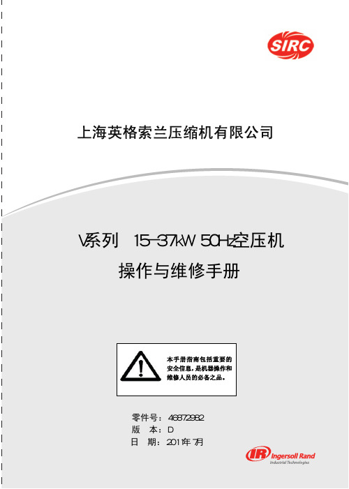
1 EMERGENCY STOP紧急停机开关按此开关便使空压机立即停机。
此开关手动复位后,空压机才能重新启动。
顺时针转动,使紧急停机开关复位,控制器显示屏会亮,指出线路电压和控制电压已具备。
2 START启动如果显示屏显示“Ready To Start”,按下此按钮使空压机启动。
如有足够用气量要求,空压机启动便自动加载。
3 STOP停机按此按钮将激活卸载停机顺序。
如空压机正在加载运行,则先卸载,维持卸载运行10到30秒(可调节),然后停机。
如空压机已在卸载运行,则立即停机。
4 UNLOAD卸载按此按钮将使空压机卸载并维持卸载状态。
显示屏显示机器在“Running Unloaded”(卸载运行)及“Mode:UNLOAD”(模式:卸载)。
5 LOAD加载如空压机已在运行且“Discharge Pressure”(排气压力)小于“Online Pressure”(回跳压力),则按此按钮将使空压机加载。
同时也会使空压机回到由“Mode of Operation”(运行模式)设定点规定的运行模式。
利用其它五个按钮可供操作者选择多种不同功能,令机器进入各种运行状态。
每个按钮的作用由当时的屏幕显示及正在执行的那个功能所决定。
6 ARROWS箭头按钮这些上下箭头按钮具有与显示屏有半相关的多种功能,当屏幕上出现功能表时,箭头按钮用来上下选点表上的项目。
7 DISPLAY BUTTONS 显示按钮显示屏幕下面三个按钮的功能是改变紧接在它们上面的屏幕最下一行的显示字符,并由这些字符定义。
二、CURRENT STATUS 当前状态CURRENT STATUS屏幕是控制器的“正常”显示状态。
CURRENT STATUS参数项Package Discharge Temperature 机组排气温度Airend Discharge Temperature 主机排气温度Injected Temperature 喷油温度Sump Pressure 分离前压力Separator Pressure Drop 油分离器压降Coolant Filter 油过滤器Invet Vacuum 进气负压Inlet Filter 进气过滤器Total Hour 总运行小时Loaded Hour 加载小时%Load Modulation 加载调节百分比Software Title and Version 软件名称及版本如30秒内不按任何按钮,控制器便自动从其它屏幕回到CURRENT STATUS屏幕。
气动绞车操作规程

1.JQH—5X48 Q型气动绞车操作规程
2.操作人员
副钻、井架工、钻工
3.操作步骤
3.1.操作前检查
1)使用前对气动绞车钢丝绳进行检查,不得存在断丝或对折压扁现象.
2)检查所有索具应在检验合格期内。
3)钢丝绳绳直径应符合技术规格,使用前,绳头用压紧螺钉固定在卷筒上,安全缠绕圈
不少于5圈。
4)压缩空气必须清洁、干燥、气源压力保持在0.6—0.8Mpa。
5)绞车钢丝绳的滑轮是否固定牢靠且旋转正常。
6)气动绞车底座固定螺栓无松动现象.
7)使用初次前,应先空负荷运转1min,然后在逐步增大提升负荷至额定拉力。
8)检查刹车刹带的磨损情况,如果刹带磨损超过2mm则需要更换后才能进行操作。
3.2.正常操作
1)操纵手柄有上升、下降、和中位三个位置。
卷筒转速与手柄角度有关,应缓慢扳
动手柄。
2)如果使用中出现异常声响,则停止工作进行检修。
3)操作平稳,禁止猛拉猛放。
4)当有障碍物挡住操作人员视线时需要有专人指挥,防止误操作.
5)严禁超负荷使用。
3.3.停止操作
1)不能长时间悬持重物,在作业结束时应将负荷卸去。
2)将钢丝绳盘列整齐后操作手柄复位。
3)关闭气源阀门.
4.相关文件和记录
《机械设备管理办法》
《JQH型气动绞车使用维护说明书》。
T30 二级压缩操作维护手册英格索兰

3
平垫 防震平垫
螺栓
金属垫片如 不平可使用
地平面 混凝土支座
典型的机组固定装置
空气进气管路安装
注意 空气进气口没有安装过滤设备请勿 运行机器。
如果机器周围的空气相对干净,则可将进 气消声滤清器安装在机头的进气口位置。如果 周围空气不干净,则应用管子将消声滤清器连 接到清洁空气源的位置。远距离进气管路应使 用 PVC 管,不要使用黑铁管或者镀锌管,因 为这些管材会增加凝水和生锈的可能性。请用 户考虑在管路中安装过滤器,以方便管路清洁 和更换。管路应尽量短且直,到压缩机机头进 气口的管径应越远越大。安装的管径不要小于 机头进气口的直径。管直径应每 3m 或有 90° 弯头的地方放大一个直径尺寸规格。同时确保 管路牢固。 如果用户将消声滤清器连接到室 外,则应加装护罩,以防止雨雪进入。英格索 兰公司还可为用户提供特殊设计的消声滤清 器。具体要求请与英格索兰公司空气中心联系
型号 2340 2475 2545 7100 15T 3000
曲轴箱容量(ml) 827 1212 2158 2365 4258 4258
压缩机润滑
A = 表示油液位已到机器加油口的螺纹位置。
5
B = 表示液位低于机器加油口的螺纹位置,需 要加油。 C = 表示油液位,无需加油。 D = 表示油液位.需要加油。 E = 表示油液位.需要加油。 F = 表示油液位置,需要加油。 G= 表示油液位已到机器加油口的螺纹位置, 无需加油.
排气管路安装
警告 压缩空气系统不要使用塑料管子,焊接的 铜质配件,橡皮软管, 焊接的接头。 所有的管路、配件、储气罐等都必须有检验证 明,以证明其至少达到装置最大工作压力的要 求。不要在压缩空气排气管路中使用 PVC 塑料 管子。所有的管螺纹接头应使用螺纹密封剂, 接头应拧紧,防止漏气。
英格索兰 操作手册
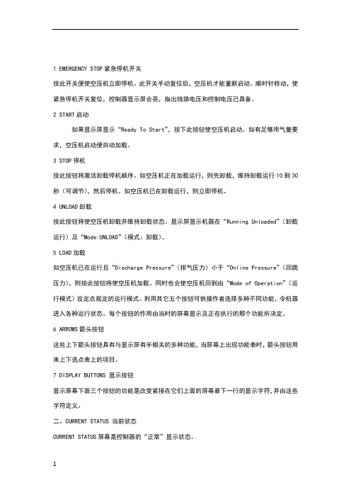
S3控制器简易手册(信息来自模拟器)一,菜单名称与定义:1,P00(默认菜单):显示空压机运行参数。
2,P01:标准设置菜单,用于更改常用空压机参数。
3,P02:故障历史记录查询。
4,P03:高级设置菜单,用于更改高级的空压机参数。
5,P04:工厂设置菜单,用于更改机组的工厂设置点。
6,P05:用于诊断和设置参数,检测模拟量的输入与输出。
7,P06:用于S3版本的升级与降级二,菜单密码:按“菜单键“后,进入密码提示栏,输入密码,按“上,下键”选择菜单,按“确认键“进入菜单。
1,P00不需要密码。
2,密码:0000,可进入:P00,PO1,P023,密码:0101,可进入:P00,P01,P02,P034,密码:****,可进入:P00,P01,P02,P03,P045,密码:****,可进入:P00,P01,P02,P03,P04,P05,P06备注:P00,P01,P02在开机状态下也可进入并修改。
P03,P04,P05,P06必须在停机状态下方可进入并修改。
只能将密码:0000告之客户。
三,P00菜单讲解:POO(默认菜单):相当于SE控制的DISPLAY键。
按“向上/向下键“在各项间进行转换。
1,Ae:主机排气温度2,Rn:运行时间3,Ld:加载时间4,Mn:距离维护的时间(此时间会随运行时间的增加而减少,到零时即到保养时间)。
5,Mn:%距维护的期限(此百分比也会逐渐减小)。
四,P01菜单讲解:相当于SE控制器的SET中的前几项。
P01:用于更改空压机的基本常用参数1,Un:调节卸载压力(上限),调整范围:(5.2BAR-----额定压力+0.2BAR)2,Ld:调节加载压力(下限),调整范围:(4.5BAR-----额定压力-0.4BAR)3,As:卸载运行到自动停车的时间(360S-3600S,0S可以设但不要设)。
4,Md:调节阀控制模式打开或关闭(ON/OFF),更改需要密码5,Eu:工程单位(度/BAR,度/KPA,度/PSI,华氏度/PSI)。
气动绞车操作规程
气动绞车操作规程调度(气动)绞车司机操作规程一、启动前的准备;1)检查绞车周围环境。
检查调度绞车安装地点5米范围内顶帮支护是否安全可靠,行车轨道有无障碍物,以便于操作和瞭望;2)检查绞车的安装固定是否平稳牢固。
临时绞车压柱戗柱牢固无松动,用地锚或混凝土基础的地锚,螺栓有无松动,弯位,目视滚筒中线是否与斜巷地段中线(提升中线)一致,绞车最突出部位距轨道外侧不小于500毫米,绞车底座不得有裂纹;3)检查制动闸和离合器。
制动闸闸带必须完整无断裂。
磨损余厚不得小于4毫米,铜或铝铆钉不得磨闸轮,闸轮磨损不得大于2毫米。
各部螺栓、销、拉杆螺栓及背帽限位销等完整齐全,无弯曲、变形。
施闸后,闸把位置在水平线以上30-40度,即应闸死,闸把位置严禁低于水平线,离合器开关是否灵活有效;4)检查钢丝绳。
无弯折、硬伤、打结、严重锈蚀,断丝不得超过规定,在滚筒上绳端固定要牢固,不准剁股穿绳,在滚筒上排列整齐,无咬绳,爬绳现象。
缠绕绳长不得超过绞车规定允许容绳量,绳径符合要求,松绳至终点时,滚筒上余绳不得少于3圈,保险绳直径与主绳直径相同并连接牢固;绳端连接装置牢固可靠,钩头有绳皮,钩头卡绳长度不少于600毫米,绳卡不少于3道,卡面距离均匀,绳卡一顺固定,护绳板完好;5)断开离合器,将气动开关手柄打到启动位置,按下制动闸,启动绞车空转,应无异常响声或震动,检查验证绞车滚筒运行方向是否与按钮标志一致;按动信号按钮,互打三次准备点,检查信号是否能实现双打对打,显示是否正确;6)检查气动马达、油雾器,保证油液充足、润滑正常。
二、启动;1)收听到准确的开车信号后,辨明开车方向,按信号指令方向启动绞车;2)操纵气动开关手柄(按箭头标记指示,向里拉为提升,向外推为下降,中间为停止),缓慢松开制动闸把,使滚筒平稳运转,达到正常运行速度;3)司机必须站在护绳板后进行操作,严禁司机在绞车两侧或滚筒前面(出绳侧)操作;严禁司机在开车的同时处理爬绳;三、运行;1)绞车运转过程中,司机应注意力集中,时刻注意观察倾听设备运转情况及信号。
- 1、下载文档前请自行甄别文档内容的完整性,平台不提供额外的编辑、内容补充、找答案等附加服务。
- 2、"仅部分预览"的文档,不可在线预览部分如存在完整性等问题,可反馈申请退款(可完整预览的文档不适用该条件!)。
- 3、如文档侵犯您的权益,请联系客服反馈,我们会尽快为您处理(人工客服工作时间:9:00-18:30)。
Product Maintenance InformationAir Powered Man Rider™ WinchModelsLS2–150RLP-L-( )-E LS2–150RLP-PHXXM-( )-E(Lever Control)(Remote Control)Save These InstructionsForm MHD56305Edition 3April 201371455570Only allow Ingersoll Rand trained technicians to perform maintenance on this product. For additional information contact Ingersoll Rand factory or nearest Distributor.For additional supporting documentation refer to Table 1 ‘Product Information Manuals’ on page 2.Manuals can be downloaded from .The use of other than genuine Ingersoll Rand replacement parts may result in safety hazards, decreased performance and increased maintenance and will invalidate all warranties.Original instructions are in English. Other languages are a translation of the original instructions.Refer all communications to the nearest Ingersoll Rand Office or Distributor.Table 1: Product Information Manuals PublicationPart/Document Number PublicationPart/DocumentNumber Product Safety Manual (Man Rider)MHD56251Product Parts Information Manual MHD56306Product Instructions ManualMHD56293INSPECTIONFrequent inspections should be performed on equipment in regular service. Refer to Product Information Manual.n Periodic InspectionRefer to Table 2 ‘Inspection Classifications’ on page 2 for suggested winchinspection classifications for Periodic Inspection intervals. Select conditions most appropriate to application.Table 2: Inspection ClassificationsConditionsNormal Heavy Severe Typical Use (operating time)InfrequentRegularContinual/ConstantLoad Range 60% of Capacity 75% of Times Used80% of Capacity 75% of Times Used100% of Capacity 75% of Times UsedInstallation Protected/Enclosed/Dry Not Sheltered/ExteriorFull ExposureAtmosphere Clean/Non-Corrosive Dirty/Non-Corrosive/Freshwater Marine Dirty/Corrosive/Saltwater Marine ClimateDry/Stable TemperatureWet/Moderate Temperature FluctuationsWet/Severe Temperature FluctuationsMaintain written records of periodic inspections to provide an accumulative basis for continuing evaluation. Inspect all items listed in the ‘Frequent Inspection’ section of the Product Information Manual. Also inspect the following at the suggested intervals recommended in Table 4 ‘Maintenance Interval Chart’ on page 3:1.Siderails and Uprights. Check for deformed, cracked or corroded maincomponents. Replace damaged parts.2.Fasteners. Check retainer rings, capscrews, nuts and other fasteners on winch,including mounting bolts. Replace if missing or damaged and tighten if loose.3.Drum and Sheaves. Check for cracks, wear or damage. Replace if necessary.4.Wire Rope. In addition to ‘Frequent Inspection’ requirements, also inspect forthe following:a.Build-up of dirt and corrosion. Clean with steam or a stiff wire brush toremove dirt and corrosion if necessary.b.Loose or damaged end connection. Replace if loose or damaged.c.Check wire rope anchor is secure in drum.d.Verify wire rope diameter. Measure the diameter of the wire rope fromcrown-to-crown throughout the life of the wire rope. Recording of the actual diameter should only be done with the wire rope under equivalent loading and in the same operating section as accomplished during previousinspections. If the actual diameter of the wire rope has decreased more than 1/64 inch (0.4 mm) a thorough examination of the wire rope should be conducted by an experienced inspector to determine the suitability of thewire rope to remain in service. Refer to Dwg. MHP0056 on page 2.B(Dwg. MHP0056)e.Inspect rope for broken strands/wires: When broken wires are evident closeto, or within, the termination, even if few in number, are indicative of high stresses at this position and can be caused by incorrect fitting of thetermination. The cause of this deterioration shall be investigated and, where possible, the termination shall be remade, shortening the rope if sufficient length remains for further use, otherwise the rope shall be discarded. One valley break may indicate internal rope deterioration, requiring closerinspection of this section of rope. When two or more valley breaks are found in one lay length, the rope should be considered for discard. If a complete strand fracture occurs, the rope shall be immediately discarded. Where broken wires are very close together, constituting a localized grouping of such breaks, the rope shall be discarded. If the grouping of such breaks occurs in a length less than 6d or is concentrated in any one strand, it may be necessary to discard the rope even if the number of wire breaks is smaller than the maximum number, refer to table on page 2Table 3: Wire RopeRope ConstructionTypeNumber Broken Wires in rope over a length 6x nominal diameter Number Broken Wires in rope over a length 30x nominal diameter6 x 19S-IWRC Single-layer rope366 x 37M-IWRC Single-layer rope10195.All Components. Inspect for wear, damage, distortion, deformation andcleanliness. If external evidence indicates damage, disassemble as required to conduct a detailed inspection. Inspect gears, shafts, bearings, sheaves, springs and covers. Replace worn or damaged parts. Clean, lubricate and reassemble.6.Brakes. Individually test brakes installed to ensure proper operation. Brakes must hold a 125% rated load at mid drum without slipping. If indicated by poor operation or visual damage, disassemble and repair brake(s). Check all brake surfaces for wear, deformation or foreign deposits. Clean and replacecomponents as necessary. Adjustments can be made to the band brake to compensate for normal brake lining wear. Refer toʽAdjustmentsʽon page 7. If brake band cannot be adjusted to hold rated load,replace the brake band assembly. Adjustments cannot be made to the disc brake.The disc brake must be repaired as described in “MAINTENANCE”sectionon page 7.7.Foundation or Supporting Structure. Check for distortion, wear and continued ability to support winch and rated load. Ensure winch is firmly mounted and that fasteners are in good condition and tight.8.Control Valve. Check control valve operation. Ensure control valve handle moves freely in both directions without sticking and automatically returns to neutral when released. Ensure locking button moves freely and locks control handle in neutral when not depressed.9.Limit Switches. Operate winch in both directions to activate limit switches. Limit switches should engage (stop winch operation) at established settings (+/- 2feet [+/- 0.6 metres]). Reset limit switch by operating winch in opposite direction.Refer to ‘Limit Switch Adjustment’ procedure in Product Information Manual.10.Emergency Stop Valve . During winch operation verify the emergency stop valve operation. Valve must stop winch operation quickly. Valve must reset properly. Refer to ‘Emergency Stop Valve’ in the “OPERATION” section in Product Information Manual for procedures.11.Overload Device. Ensure overload device is properly set to stop the winch when loads exceed 150% (+/- 25%) of winch rated capacity. If winch does not shut down, contact your distributor or the factory for repair information.12.Slack Line Detector. Inspect rollers for wear and grooves or ridges. Replaceworn or grooved rollers. Check arms move freely and activate sensor valve.Ensure rollers rotate freely. Check sensor valve plunger operation. If damaged or stiff, replace sensor valve.13.Press Roller. Inspect rollers for wear and grooves. Ensure rollers freely rotate.Replace rollers if worn or grooved. Replace bearings if rotation is rough or stiff.14.Emergency Lowering Device. Provide auxiliary supply air to emergencylowering power entry port and activate valve. Verify winch operation.15.Drum Guard. Verify fasteners are tight and in good condition. Ensure guard isin good condition and panels are correctly positioned.bels and Tags. Check for presence and legibility of labels. Replace if damagedor missing.n Records and ReportsInspection records, listing all points requiring periodic inspection should be maintained for all load bearing equipment. Written reports, based on severity of service, should be made on the condition of critical parts as a method ofdocumenting periodic inspections. These reports should be dated, signed by the person who performed the inspection, and kept on file where they are readily available for review.n Maintenance IntervalsRefer to Table 4 ‘Maintenance Interval Chart’ on page 3 for recommended maintenance schedule.•Perform an annual winch load test for all applications.Table 4: Maintenance Interval ChartNote: Hours are for actual winch drum rotation.* Do not disassemble air cylinder unless brake operation or visual inspection indicates a requirement.Table 5: Maintenance Interval ChartNote: Hours are for actual winch drum rotation.* Do not disassemble air cylinder unless brake operation or visual inspection indicates a requirement.INSPECTION REPORTIngersoll Rand L2–150RLP Series Air WinchesModel Number:Date:Serial Number:Inspected by:Reason for Inspection: (Check Applicable Box)1. Scheduled Periodic Inspection:(_____ Months _____ Years)Operating Environment:Normal ____Heavy____Severe ____2. Discrepancy(s) noted during Frequent Inspection3. Discrepancy(s) noted during maintenance4. Other: ___________________________Refer to the Product Information Manual and Product Parts Information Manual and “INSPECTION” section for general inspection criteria. Also, refer to appropriate National Standards and Codes of practice. If in doubt about an existing condition, contact the nearest Ingersoll Rand Distributor or the factory for technical assistance.COMPONENTCONDITION CORRECTIVE ACTION NOTESPassFailRepairReplaceUprights and Siderails Drum Band Brake (125% Load Test) Disc Brake (125% Load Test) Drum Band Brake (Visual Inspection)Disc Brake (Visual Inspection) Motor ControlsLimit Switches Air System Fasteners--- Emergency Stop Valve Overload Device --- Reduction Gears Labels and Tags --- Output Shaft Shafts Drum Guard Wire Rope Wedge--- Emergency Air supply Tank or System--- Slack Line Devise --- Press Roller Wire Rope--- Other Components (list in NOTES section)TESTINGPassFailNOTES Operational (No Load) Operational (10% Load)Operational (Maximum Test Load*)*Maximum test load is 125% of rated line pull. Testing to more than 125% of rated load may be required to set overload device or comply with standards and regulations set forth in areas outside the USA.This form may be photo copied and used as an inspection record.TROUBLESHOOTINGThis section provides basic troubleshooting information. Determination of specific causes to problems are best identified by thorough inspections performed by personnel instructed in safety, operation and maintenance of this equipment. The chart below provides a brief guide to common winch symptoms, probable causes and remedies.MAINTENANCE•Never perform maintenance on the winch while it is supporting a load.•Before performing maintenance, tag controls:WARNING - DO NOT OPERATE, EQUIPMENT BEING REPAIRED.•Only allow Ingersoll Rand trained Technicians to perform maintenance on this winch.•Shut off air system and depressurize air lines before performing any maintenance.•Do not use Trichloroethylene to clean parts.•Use of other than genuine Ingersoll Rand parts may result in safety hazards, decreased performance and increased maintenance and may invalidate all warranties.•After performing any maintenance on the winch, test winch to 125% of its rated line pull at mid drum before returning to service. (Testing to more than 125% of rated line pull may be required to comply with standards and regulations set forth in areas outside the USA.)•Refer to Product Information and Safety Manuals for specific information. n GeneralCorrect disassembly (to prevent loss or damage of good parts), repair, assembly, testing and adjusting are critical to proper winch operation. Maintenance procedures are technical in nature and require training and experience to accomplish correctly. In addition, repair and testing require specialized equipment that is not typically found at the products mounting site.Proper use, inspections and maintenance increase the life and usefulness of your Ingersoll Rand equipment. During assembly, lubricate gears, nuts, capscrews and all machined threads with applicable lubricants. Use of anti-seize compound and/ or thread lubricant on capscrew and nut threaded areas prevents corrosion and allows for easy disassembly of components.It is extremely important that anyone involved with maintaining the product be familiar with the servicing procedures of these products and be physically capable of conducting the procedures. These personnel shall have skills that include:1.Proper and safe use and application of mechanics’ common hand tools as wellas special Ingersoll Rand or recommended tools.2.Safety procedures, precautions and work habits established by acceptedindustry standards.Ingersoll Rand cannot know of or provide all the procedures by which product operations or repairs may be conducted and the hazards and/or results of each method. If operation or maintenance procedures not specifically recommended by the manufacturer are conducted, it must be ensured that product safety is not endangered by the actions taken. If unsure of an operation or maintenance procedure or step, personnel should place the product in a safe condition and contact supervisors and/or the factory for technical assistance.•Refer to the Product Parts Information Manual for drawings unless specified elsewhere.Drawing No. from Parts ManualMHD56306Page No.MHP27284MHP272910MHP273016MHP273113MHP273214MHP28076MHP281112MHP28128MHP28174MHP281818MHP310020n Maintenance IntervalsRefer to Table 4 ‘Maintenance Interval Chart’ on page 3 for recommended maintenance schedule.n Adjustmentsn Limit SwitchesRefer to ʽLimit Switchesʽ section in Product Information Manual.n Disc BrakeNo brake adjustment is required. Refer to Dwg. MHP2849 on page 7, A. Piston; B. Friction Plate; C. Drive Plate; D. Reaction Plate; E. 0.047 inch minimum (1.2 mm minimum).1.Remove motor as described in ‘Motor Removal’ section on page 8.2.Remove the reaction plate (57), splined hub (53), friction plates (55) and (58),and drive plates (56).3.Inspect the friction plates (55) and (58) for wear. If friction plate thickness isuneven or is less than 0.047 in (1.2 mm), replace all friction plates.No further disassembly is required, if only the brake friction discs are being inspected. Ensure friction and drive plates are assembled in the correct order. Refer to ‘Disc Brake Assembly’ on page 9.(Dwg. MHP2849)NOTICE•Original brake disc thickness is 0.059 in (1.5 mm)n Overload DeviceWARNING•Overload is factory set and sealed with red paint and should not be adjusted without consulting an Ingersoll Rand trained technician.B(Dwg. MHP2683)1.Connect winch to an air supply.2.Release securing screw and adjusting screw in order to increase or decrease theSWL (increase SWL by tightening the adjusting screw). Adjustment must be made for an overload of 135% maximum of SWL.3.Tighten securing screw.4.Check winch operation at rated load. If necessary, repeat adjustment.n Automatic Band Drum BrakeRefer to Dwg. MHP2880 on page 8.1.Loosen locknut ‘B’.2.Tighten nut ‘A’ until the adjustment dimension 0.43 to 0.51 inch (11 to 13 mm)is achieved.3.Tighten locknut ‘B’.4.Check brake operation.(Dwg. MHP2880)n Disassemblyn General Disassembly InstructionsThe following instructions provide necessary information to disassemble, inspect, repair, and assemble product. Parts drawings are provided in Product Parts Information Manual.If a product is being completely disassembled for any reason, follow the order of topics as they are presented. It is recommended that all maintenance work on product be performed in a clean dust-free work area.In the process of disassembling product, observe the following:1.Never disassemble product any further than is necessary to accomplish neededrepair. A good part can be damaged during the course of disassembly.2.Never use excessive force when removing parts. Tapping gently aroundperimeter of a cover or housing with a soft hammer, for example, is sufficient to break the seal.3.Do not heat a part with a flame to free it for removal, unless part being heatedis already worn or damaged beyond repair and no additional damage will occur to other parts.In general, products are designed to permit easy disassembly and assembly. The use of heat or excessive force should not be required.4.Keep work area as clean as practical, to prevent dirt and other foreign matterfrom getting into bearings or other moving parts.5.All seals, gaskets and ‘O’ rings should be discarded once they have beenremoved. New seals and ‘O’ rings should be used when assembling product.6.When grasping a part in a vise, always use leather-covered or copper-coveredvise jaws to protect the surface of part and help prevent distortion. This isparticularly true of threaded members, machined surfaces and housings.7.Do not remove any part which is a press fit in or on a subassembly unless removalof that part is necessary for repairs or replacement.8.When removing ball bearings from shafts, it is best to use a bearing puller. Whenremoving bearings from housings, drive out bearing with a sleeve slightlysmaller than outside diameter of bearing. The end of sleeve or pipe whichcontacts bearing must be square. Protect bearings from dirt by keeping them wrapped in clean cloths.n External Components RemovalRefer to component disassembly sections for further repair.1.Disconnect and tag all external air lines.2.Remove filter, regulator and lubricator (FRL) assembly from spacer (66).3.Remove drum guards. Refer to drum guard disassembly.4.Remove press roller assembly from spacer. Refer to press roller disassembly.5.Remove slack wire rope device from spacer. Refer to press roller disassembly.6.Remove limit switch assembly. Refer to limit switch disassembly.n Motor and Reduction Gear RemovalRefer to Dwg. MHP2812 and MHP2728.1.Shut off and bleed down main air supply to winch.2.Disconnect and tag air lines.3.Stand winch in a vertical position, with the motor end up. Ensure winch isproperly supported.4.Remove four capscrews (86) and washers (125) that secure motor and controlvalve assembly to upright (62).5.Carefully pull motor assembly from winch.6.Clean capscrews (86) and threaded holes with Loctite® 7063 or equivalent sothey are free of Loctite® residue.7.Store motor in a clean area until needed. If repair is required refer to specificdisassembly sections.n Drum Guard DisassemblyRefer to Dwg. MHP2817.1.Remove capscrews (171).2.Remove drum guard (216), left panel (217) and right panel (218).n Automatic Band Drum Brake DisassemblyRefer to Dwg. MHP2811.1.Disconnect and tag the air lines.2.Loosen nut (151) until brake band (111) is slack on drum.3.Remove one cotter pin (113) from each pin (112) and tap out pins (112) frombrake band ends.4.Remove brake band (111) and adjustment screw (149). Remove capscrews (156)and lockwashers (64) that secure housing (147) to side rail (68). DO NOTdisassemble brake cylinder assembly. Contact an Ingersoll Rand trained service technician for cylinder disassembly and repair.n Limit Switch DisassemblyRefer to Dwg. MHP2730.CAUTION•It is not recommended to disassemble limit switch. Contact factory if repair is required.1.Remove and tag hose connections if not already done.2.Remove nuts (504) from rods (502). Remove cover (505), gasket (490) andhousing (486) from limit switch adapter (450).3.Remove capscrews (499) and pull spindle switch assembly (501) from limit switchadapter (450).4.Store limit switch assembly in a clean, dry area until winch reassembly.n Press Roller DisassemblyRefer to Dwgs. MHP2728 and MHP2731.press ends of springs (167) and (169) to disengage from spacer (66) and pinon press roller arm (163).CAUTION•Use care when releasing springs (167) and (169) from press roller. Springs are under tension.2.Remove capscrews (183) and lockwashers (73). Remove press roller assemblyfrom spacer (66).3.Remove capscrews (161) and washers (162) from both sides of roller arm (181).Remove frames (176) and springs (169).4.Remove capscrews (161) and washers (162) from both sides of roller arm (181).Remove press rollers (184).n Slack Line Device DisassemblyRefer to Dwgs. MHP2732.1.Remove and tag hose connections if not already done.2.Remove locknuts (301) and washers (307) from shoulder screws (310).3.Remove spacers (308) and lift off slack wire arm assembly.4.Tap shoulder screws (310) from uprights (62) and remove bearings (309).5.Remove capscrews (302) and lockwashers (73) from axle (304).6.Remove locknuts (301) and lockwashers (73) from roller axle (305). Separate arms(303), rollers (306) and axles (304) and (305).7.Remove capscrews (324) and lockwashers (2) from protector (323).8.Remove protector (323) and sensor valve (327) from upright (62).n Winch Base and Drum DisassemblyRefer to Dwgs. MHP2728, MHP2807 and MHP2812. Refer to ‘Motor and Reduction Gear Removal’ section on page 8 to remove motor assembly from the winch.1.Remove external components. Refer to ‘External Components Removal’ sectionon page 8.2.Stand winch in a vertical position with motor end up.3.Remove capscrews (86), and washers (125) that secure motor, reduction gearand brake assembly to drum end cover (76). Set assembly to one side for further disassembly if needed.4.Remove capscrews (65) and (67), nuts (63) and lockwashers (64) to removespacers (66) and lifting lugs (69).5.Remove capscrews (67), nuts (63) and lockwashers (64) to remove siderails (68).6.Remove upright (62) and tube (70).7.Remove capscrews (50) and lockwashers (73). Separate drum end coverassembly from upright (62).8.Remove bearing (76) and oil seal (77) from drum (60) if not removed with drumend cover (78).9.Carefully turn drum over so limit switch end is up.10.Remove upright (62) from drum (60).11.Remove capscrews (50) and lockwashers (73) from drum end cover (78).12.Remove drum end cover (78) from upright (62).13.Remove bearing (76) and oil seal (77) from drum (60) if not removed with drumend cover (78).n Disc Brake DisassemblyRefer to Dwg. MHP2807.1.Remove capscrews (25) (black) allowing brake and reducer assembly to beremoved together.e the two threaded puller holes in the piston (51) to remove piston (51) andbrake reaction plate (57) from brake housing (41).3.Remove drive plates (56), friction plates (55) and (58), spacer (54) and splinedhub (53). Note position for later assembly.4.Remove ‘O’ ring (16) and ‘O’ ring (52) from piston (51) and discard.n Reduction Gear DisassemblyRefer to Dwg. MHP2807.1.Remove disc brake assembly refer to on page 92.Remove fill plug (14) and drain oil from reduction gear into a suitable container.3.Remove capscrews (24) and (25) to separate reduction gear assembly from brakehousing (41).4.Remove capscrews (22) and washers (23) that secure reduction gear end cover(15).5.Remove retainer ring (12) from gear shaft (20).•It may be necessary to use a small amount of air pressure in fill hole of reduction gear end cover (15) to separate from housing (27).6.Remove and discard ‘O’ ring (16) on reduction gear end cover (15).7.It is not necessary to remove bearing (39) from reduction gear end cover (15)unless damaged. Replace as necessary.8.Remove bearing (13) and oil seal (17). Replace seal and bearing if necessary.9.Remove bearing (21) and ring gear (19).10.Support end cover (15) and tap out shaft (20).11.Remove retainer ring (36) from sun gear (34).12.Support reducer housing (27) and gently tap out sun gear (34).13.Tap out gear shafts (33) and remove planet gears (31), spacers (30), needlebearings (28) and bearing rings (29).14.Remove retainer ring (49).15.Remove sun gear (34).16.Remove retainer ring (36) and bearing (35).17.Remove and discard gasket (26) and ‘O’ ring (16) from brake housing (41).18.Remove and replace bearing (38) if necessary.n Motor DisassemblyRefer to Dwg. MHP2812.1.Remove motor assembly as described in ‘Motor and Reduction Gear Removal’on page 8.2.Remove control valve assembly (100) from motor assembly.3.Remove capscrews (103) and emergency stop end cover (185).4.Remove and discard gasket (101).5.Remove capscrews (107) and remove motor cover (97) from motor housing (87).6.Remove and discard ‘O’ rings (90).7.Remove valves (105) and springs (96) from motor cover (97).8.Remove ‘O’ rings (94) only if necessary. ‘O’ rings will need to be cut for removal.•The two bearings (91) located in the motor housing (87) are bonded with Loctite® 603 or equivalent. Remove idle gear (104) and drive gear (92) only if replacement is necessary; use a bearing punch (IR pn: 96441232) orstandard drift punch and a hammer. Refer to Dwg. MHP2644on page 11.9.To remove both bonded bearings (91) from motor housing (87), it is necessaryto use a bearing punch and hammer. Two or three strikes are enough.10.If replacement is necessary, remove bearings (91) from drive gear (92) and idlegear (104) (use a suitable bearing extractor).11.Remove check valve (83) and ball (84) from motor housing (87). Emergency Stop End Cover:1.Remove and discard ‘O’ rings (90).2.Remove setscrew (180).3.Remove ball (84).4.Remove valve seat (186).5.Remove seal (189) and axle (188).6.Remove and discard ‘O’ rings (187).7.Remove spring (193).8.Unscrew clamping screw (102).9.Unscrew regulating screw (192) and remove and discard ‘O’ ring (191).10.Remove valve seat (205).11.Remove spring (213).12.Remove capscrews (214).13.Separate caps (202) and (211), washers (208) and (206), sleeve (209) anddiaphragm (212).14.Remove seals (203) and (210).15.Pull stop nut (194) and separate plunger (198) with diaphragm (196) from baseplate (199).16.Unscrew nut (194) and remove plunger (198) and washer (195).17.Remove and discard ‘O’ ring (197) .18.Install a screw (dia. M5) in threaded hole on base plate (199) and pull it frommotor cover (97).n Control Valve DisassemblyRefer to Dwg. MHP2729.1.To separate control valve (100) from motor assembly, remove capscrews (137)and (168) with lockwashers (2).2.Remove capscrews (118) and lockwashers (2) from stop plate (119). Remove stopplate.3.Partially remove capscrew (126) just far enough to allow emergency stophousing assembly to be removed. Place emergency stop housing assembly to one side for later disassembly.4.Remove spools (142) from valve housing (135).pletely remove capscrew (126) and lockwasher (125).6.Remove lever assembly, coupling (124) and spring (116).7.Do not disassemble handle unless repairs are needed. To disassemble handle,tap out pin (120) and unscrew cap (121). Remove handle spool (123) and spring (130).8.Remove retainer (140), spindle shaft (131) and gear (138).9.Remove retainer (140), spindle shaft (131) and gear cam (139).10.Remove pins (132) from spindle shafts (115).11.Remove bushings (133) and bushings (141).Emergency Stop:Refer to Dwg. MHP2729.1.Remove emergency stop valve (164) from end cover (172).2.Remove and discard ‘O’ rings (175).3.Unscrew and remove valve (165) with ‘O’ ring (171), ‘O’ ring (166) and protector(170).4.Remove retainer rings (178).5.Remove springs (177) and balls (84).6.Unscrew check valve (83) and remove ball (84).7.Remove and discard ‘O’ rings (166).n 2 Function Emergency Stop Pendant Disassembly (optional) Refer to Dwg. MHP2818.1.Disconnect hoses from pendant assembly (600).2.Remove fittings (152).3.Remove lifting eye (617), if necessary.4.Tap out pin (618) to remove the levers (619).5.Unscrew and remove check valve (83) and ball (84).6.Remove setscrew (173) to remove the valve assemblies (165).7.Remove protector (170), ‘O’ rings (166) and (171) from the valve (165).8.Remove plugs (623) to remove the springs (177) and balls (84).9.Remove emergency stop button (164).10.Remove retainer ring (621) and exhaust washer (615) from handle (622).n Cleaning, Inspection and RepairRefer to Product Parts Information Manual for item numbers referenced in the “Cleaning, Inspection and Repair” section.n CleaningClean all winch component parts in solvent (except drum brake bands and disc brake friction plates). The use of a stiff bristle brush will facilitate removal of accumulated dirt and sediments on housings, frame and drum. If bushings have been removed it may be necessary to carefully remove old Loctite® from bushing bores. Dry each part using low pressure, filtered compressed air. Clean drum brake band using a wire brush or emery cloth. Do not wash drum brake band in solvent. If drum brake band lining is oil soaked, it must be replaced.n InspectionAll disassembled parts should be inspected to determine their fitness for continued use. Pay particular attention to the following:Inspect gears for-worn, cracked or broken teeth. Replace if necessary.Inspect bushings for•-wear, scoring or galling. Replace if necessary.Inspect shafts for•-ridges caused by wear. Replace if necessary.•-scoring or galling.Inspect all threaded items for•-damaged threads. Replace if necessary.Inspect drum band brake lining for•-oil, grease and glazing. If drum band brake lining is oil-soaked, excessively greasy or overly glazed, replace brake band. Remove small glazed areas ofband brake lining by sanding lightly with a fine grit emery cloth.•-thickness of drum band brake lining. If drum brake band lining is less than0.062 in. (2 mm) thick anywhere along the edges, replace brake bandassembly.Inspect motor housing gear bores for•-wear or scoring. For any large scratches or uneven/excessive wear patterns, replace motor housing.Inspect motor gears (92) and (104) for•-ridges or excessive grooving on outside diameter of gears.•-contact between gears and gear housing.Inspect press roller and slack wire device for•-wear, grooves or scoring of rollers. Replace if any of these conditions exist.•-smooth rotation. Rollers must operate without binding and without excessive side-to-side play.。