Cobalt-Base High-Temperature Alloys
浦发产品性能指南说明书
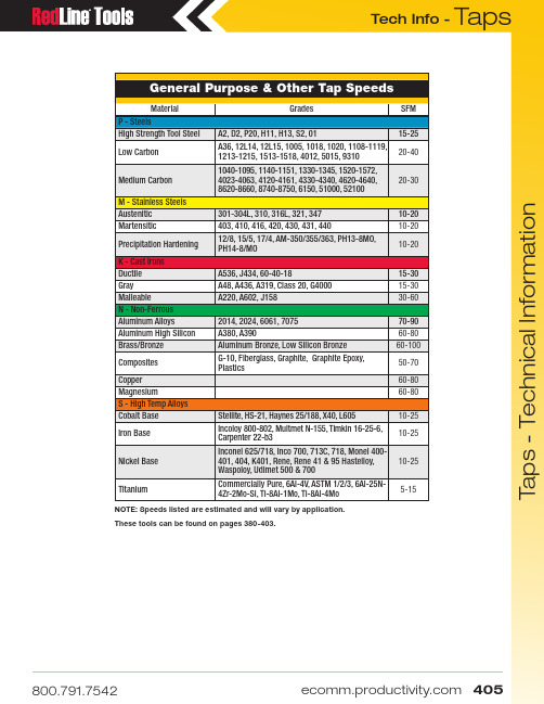
T a p s T a p s - T e c h n i c a l I n f o r m a t i o nGeneral Purpose & Other Tap SpeedsMaterialGradesSFM P - SteelsHigh Strength Tool Steel A2, D2, P20, H11, H13, S2, 0115-25Low Carbon A36, 12L14, 12L15, 1005, 1018, 1020, 1108-1119, 1213-1215, 1513-1518, 4012, 5015, 931020-40Medium Carbon 1040-1095, 1140-1151, 1330-1345, 1520-1572, 4023-4063, 4120-4161, 4330-4340, 4620-4640, 8620-8660, 8740-8750, 6150, 51000, 5210020-30M - Stainless Steels Austenitic 301-304L, 310, 316L, 321, 347 10-20Martensitic403, 410, 416, 420, 430, 431, 44010-20Precipitation Hardening 12/8, 15/5, 17/4, AM-350/355/363, PH13-8MO, PH14-8/MO10-20K - Cast Irons Ductile A536, J434, 60-40-1815-30Gray A48, A436, A319, Class 20, G400015-30MalleableA220, A602, J15830-60N - Non-Ferrous Aluminum Alloys2014, 2024, 6061, 707570-90Aluminum High Silicon A380, A39060-80Brass/Bronze Aluminum Bronze, Low Silicon Bronze60-100Composites G-10, Fiberglass, Graphite, Graphite Epoxy, Plastics50-70Copper 60-80Magnesium60-80S - High Temp Alloys Cobalt Base Stellite, HS-21, Haynes 25/188, X40, L60510-25Iron Base Incoloy 800-802, Multmet N-155, Timkin 16-25-6, Carpenter 22-b310-25Nickel Base Inconel 625/718, Inco 700, 713C, 718, Monel 400-401, 404, K401, Rene, Rene 41 & 95 Hastelloy, Waspoloy, Udimet 500 & 70010-25TitaniumCommercially Pure, 6Al-4V, ASTM 1/2/3, 6Al-25N-4Zr-2Mo-Si, Ti-8Al-1Mo, Ti-8Al-4Mo5-15NOTE: Speeds listed are estimated and will vary by application.These tools can be found on pages 380-403.T a p s T a p s - T e c h n i c a l I n f o r m a t i o nMachine Screw Sizes NC & NFFractional Sizes NC & NFNom. SizeTap RecommendedTap Drill Probable Hole Size Actual % ThreadNom. SizeTap RecommendedTap Drill Probable Hole Size Actual % ThreadDrill Decimal Drill Decimal 0 - 803/64.0469.0484711/4 - 283.2130.2168721 - 6453.0595.0610595/16 - 18F .2570.2608721 - 7253.0595.0610675/16 - 24I .2720.2761672 - 5650.0700.0717623/8 - 165/16.3125.3169722 - 6450.0700.0717703/8 - 24Q .3320.3364713 - 4847.0785.0804697/16 - 14U .3680.3726703 - 5646.0810.0829697/16 - 20W .3860.3906724 - 4043.0890.0910651/2 - 1327/64.4219.4266734 - 4842.0935.0955611/2 - 2029/64.4531.4578655 - 4039.0995.1018719/16 - 1231/64.4844.4892685 - 4438.1015.1038729/16 - 1833/64.5156.5204586 - 3236.1065.1091715/8 - 1117/32.5313.53620756 - 4033.1130.1156695/8 - 1837/64.5781.5831588 - 3229.1360.1389623/4 - 1021/32.6562.6613688 - 3629.1360.1389703/4 - 1611/16.6875.692507110 - 2425.1495.1527697/8 - 949/64 .7656.77087210 - 3221.1590.1622687/8 - 1413/16.8125.81776212 - 2417.1730.176573 1 - 87/8.8750.88097312 - 2815.1800.183570 1 - 1259/64.9219.9279671/4 - 207.2010.2048701 - 1415/16.9375.943561Taper Pipe TapsRoll Form Taps - App. 65% ThreadNom. Size Tap DrillTap Drill Tap Drill NPT NPTF 1/16 - 27D C 0 - 805412-2881/8 - 27Q Q 1 - 64 1.65MM 1/4-2011/4 - 187/167/16 1 - 72 1.7MM 1/4-28A 3/8 - 189/169/16 2 - 565/645/16-187.3MM 1/2 - 1445/6445/64 2 - 642MM 5/16-24M 3/4 - 1429/3229/32 3 - 48433/8-168.8MM 1 - 11-1/21-9/641-9/64 3 - 56 2.3MM 3/8-24T 1-1/4 - 11-1/21-31/641-31/64 4 - 40397/16-14Y 1-1/2 - 11-1/21-47/641-23/32 4 - 48 2.6MM 7/16-2010.5MM 2 - 1-1/22-13/642-3/16 5 - 40331/2-1311.8MM 2-1/2 - 82-5/82-39/64 5 - 44 2.9MM 1/2-2012.0MM 3 - 83-1/43-15/64 6 - 321/89/16-1217/32——— 6 - 40 3.2MM 9/16-1813.5MM ———8 - 32255/8-1114.75MM ———8 - 36245/8-1815.25MM ———10 - 2411/643/4-1045/64———10 - 32163/4-1623/32———12 - 245MM——Tap Drill ChartMetric Tap Drill Size(Recommended Drill Sizes Suitable for 6H Tolerance)Tap Size Cutting Tap Drill Size Roll Form Tap Drill Size Tap Size Cutting Tap Drill Size Roll Form Tap Drill Size Tap SizeCutting Tap Drill SizeM1.6 x 0.35 1.25MM —M10 x 1.58.5MM 9.20MMM24 x 353/64M1.8 X 0.35 1.45 MM —M10 x 1.258.75MM U M24 x 222MM M2 x 0.4 1.60MM —M12 x 1.7513/327/16M27 x 324MM M2.2 x 0.45 1.75MM —M12 x 1.2510.75MM .447*M27 x 263/64M2.5 x 0.45 2.05MM —M14 x 212MM 13MM M30 x 3.51-3/64*M3 x 0.5 2.5MM 7/64M14 x 1.512.5MM 13.20MM M30 x 21-7/64*M3.5 x .06 2.9MM 3.2MM M16 x 214MM 15MM M33 x 3.51-11/64*M4 x 0.7 3.3MM #27M16 x 1.514.5MM 15.25MM M33 x 231MM*M4.5 x 0.75 3.75MM 4.10MM M18 x 1.515.5MM 16.25MM M36 x 432MM*M5 x 0.8#19 4.60MM M18 x 1.516.5MM 17.25MM M36 x 333MM*M6 x 15MM 5.50MM M20 x 2.517.5MM 47/64M39 x 435MM*M7 x 1 6MM 6.50MMM20 x 1.518.5MM .757*M39 x 336MM*M8 x 1.25H L M22 x 2.519.5MM ———M8 x 1J7.50MMM22 x 1.520.5MM—* Reaming RecommendedT a p s T a p s - T e c h n i c a l I n f o r m a t i o n(SS) = Small Shank (LS) = Large ShankSee page 346 for overall lengths available.Machine Screw Tap (NC & NF) DimensionsSizeOALThread Length SquareLength Shk øSquare #0 (.060)1-5/85/163/16.141.110#1 (.073)1-11/163/83/16.141.110#2 (.066)1-3/47/163/16.141.110#3 (.099)1-13/161/23/16.141.110#4 (.112)1-7/89/163/16.141.110#5 (.125)1-15/165/83/16.141.110#6 (.138)211/163/16.141.110#8 (.164)2-1/83/41/4.168.131#10 (.190)2-3/87/81/4.194.152#12 (.216)2-3/815/169/32.220.165Fractional Size Tap (NC & NF) DimensionsSize OAL Thread Length SquareLength Shk øSquare 1/42-1/215/16.255.1915/162-23/321-1/83/8.318.2383/82-15/161-1/47/16.381.2867/163-5/321-7/1613/32.323.2421/23-3/81-21/327/16.367.2759/163-19/321-21/321/2.429.3225/83-13/161-13/169/16.480.36011/164-1/321-13/165/8.542.4063/44-1/4211/16.590.4427/84-11/162-7/323/4.697.52315-1/82-1/213/16.800.6001-1/85-7/162-9/167/8.896.6721-1/45-3/42-9/161 1.021.7661-3/86-1/1631-1/16 1.108.8311-1/26-3/831-1/81.233.925Pipe Tap, Straight & Taper (NC & NF) DimensionsSizeOALThread Length Square LengthShk øSquare1/16 – 272-1/811/163/8.3125.2341/8 – 272-1/83/43/8.3125(SS).2341/8 – 272-1/83/43/8.4375(LS).3281/4 – 182-7/161-1/167/16.5625.4213/8 – 182-9/161-1/161/2.7000.5311/2 – 143-1/81-3/85/8.6875.5153/4 – 143-1/41-3/811/16.9063.6791 – 11-1/23-3/41-3/413/16 1.1250.8431-1/4 – 11-1/241-3/415/16 1.3125.9841-1/2 – 11-1/24-1/41-3/41 1.5000 1.1252 – 11-1/24-1/21-3/41-1/81.8750 1.406Pulley Tap DimensionsSize Thread Length Square Length Shk øSquare Neck Length Ground Length 1/415/16.255.1913/81-1/25/161-1/83/8.318.2383/81-9/163/81-1/47/16.381.2863/81-5/87/161-7/161/2.444.3337/161-11/161/21-21/329/16.507.3801/21-11/165/81-13/1611/16.633.4755/823/423/4.759.5693/42-1/4Metric Tap DimensionsSizeOAL Thread Length Square Length Shk øSquare Inch Blank M1.6 x .351-5/85/163/16.141.110#0M2 x .401-3/47/163/16.141.110#2M2.5 x .451-13/161/23/16.141.110#3M3 x .501-15/165/83/16.141.110#5M3.5 x .60211/163/16.141.110#6M4 x .702-1/83/41/4.168.131#8M4.5 x .752-3/87/81/4.194.152#10M5 x .802-3/87/81/4.194.152#10M6 x 12-1/215/16.255.1911/4M6.3 x 12-1/215/16.255.1911/4M7 x 12-23/321-1/83/8.318.2385/16M8 x 1.252-23/321-1/83/8.318.2385/16M10 x 1.502-15/161-1/47/16.381.2863/8M12 x 1.753-3/81-21/327/16.367.2751/2M14 x 23-19/321-21/321/2.429.3229/16M16 x 23-13/161-13/169/16.480.3605/8M18 x 2.504-1/321-13/165/8.542.40611/16M20 x 2.504-15/32211/16.652.48913/16M24 x 34-29/322-7/323/4.760.57015/16M30 x 3.505-7/162-9/161 1.021.7661-3/16M36 x 46-1/1631-1/81.233.9251-7/16Small Shank Extension TapDimensionsSize NC/NF Thread Length SquareLength Shk øSquare 6 – 32NC 11/163/16.097.073 8 – 32NC 3/41/4.123.092 10 – 24NC 7/81/4.136.102 10 – 32NF 7/81/4.136.102 1/4 – 20NC 15/16.185.139 1/4 – 28NF 15/16.185.139 5/16 – 18NC 1-1/83/8.240.180 5/16 – 24NF 1-1/83/8.240.180 3/8 – 16NC 1-1/47/16.275.206 3/8 – 24NF 1-1/47/16.275.206 7/16 – 14NC 1-7/1613/32.323.242 7/16 – 20NF 1-7/1613/32.323.242 1/2 – 13NC 1-21/327/16.367.275 1/2 – 20NF 1-21/327/16.367.275 5/8 – 11NC 1-13/169/16.480.360 5/8 – 18NF 1-13/169/16.480.360 3/4 – 10NC 211/16.590.442 3/4 – 16NF211/16.590.442Fractional SizesFractional SizesMachine Screw Sizes Fractional SizesDryseal American National Standard Straight Pipe Thread Form (NPSF)。
ASTM B719-00镍铬钼钴钨铁硅合金棒材
Designation:B719–00Standard Specification forNickel-Chromium-Molybdenum-Cobalt-Tungsten-Iron-Silicon Alloy(UNS N06333)Bar1This standard is issued under thefixed designation B719;the number immediately following the designation indicates the year of original adoption or,in the case of revision,the year of last revision.A number in parentheses indicates the year of last reapproval.A superscript epsilon(e)indicates an editorial change since the last revision or reapproval.1.Scope1.1This specification covers wrought alloy UNS N06333in the form of hot-finished and cold-finished bars andflats intended for heat resisting applications and general corrosive service.1.2The values stated in inch-pound units are to be regarded as the standard.2.Referenced Documents2.1ASTM Standards:B880Specification for General Requirements for Chemical Check Analysis Limits for Nickel,Nickel Alloys and Cobalt Alloys2E8Test Methods for Tension Testing of Metallic Materials3 E10Test Method for Brinell Hardness of Metallic Materi-als3E18Test Methods for Rockwell Hardness and Rockwell Superficial Hardness of Metallic Materials3E29Practice for Using Significant Digits in Test Data to Determine Conformance with Specifications4E140Hardness Conversion Tables for Metals3E1473Test Methods for Chemical Analysis of Nickel, Cobalt and High-Temperature Alloys53.Terminology3.1Definitions of Terms Specific to This Standard:3.1.1bars—material of round,hexagonal,octagonal,or square solid section,furnished in straight lengths,1⁄4in.[6.35 mm]and over in diameter or size.3.1.2flats—material1⁄4to10in.[6.35to254mm],inclu-sive,in width and120in.[3.05mm]and over in thickness.4.Ordering Information4.1It is the responsibility of the purchaser to specify all requirements that are necessary for the safe and satisfactory performance of material ordered under this specification. Examples of such requirements include,but are not limited to, the following:4.1.1Alloy name or UNS number.4.1.2Quantity.4.1.3ASTM Designation and year of issue.4.1.4Section(round,square,hexagonal,and so forth). 4.1.5Dimensions,including length.4.1.6Finish,hot or cold.4.1.7Certification—state if certification is required(Section 16).4.1.8Samples for Product(Check)Analysis—State whether samples shall be furnished.4.1.9Purchaser Inspection—If a purchaser wishes to wit-ness tests or inspections of material at the place of manufac-ture,the purchase order must so state indicating which tests or inspections are to be witnessed.5.Material and Manufacture5.1All material shall be furnished in the annealed condi-tion,except that cold-drawn hexagons may be given a cold draw sizing pass subsequent to thefinal anneal.N OTE1—Hot-finished rectangular bar in widths10in.[254mm]and under may be furnished as hot-finished plate with sheared or cut edges.6.Chemical Requirements6.1The material shall conform to the requirements as to chemical composition specified in Table1.6.2If a product(check)analysis is performed by the purchaser,the material shall conform to the product(check) analysis variations per B880.7.Mechanical and Other Requirements7.1The mechanical properties of the material at room temperature shall conform to those shown in Table2.1This specification is under the jurisdiction of ASTM Committee B02onNonferrous Metals and Alloys and is the direct responsibility of SubcommitteeB02.07on Refined Nickel and Cobalt and Their Alloys.Current edition approved May10,2000.Published June2000.Originallypublished as st previous edition B719-83(1994)2Annual Book of ASTM Standards,V ol02.04.3Annual Book of ASTM Standards,V ol03.01.4Annual Book of ASTM Standards,V ol14.02.5Annual Book of ASTM Standards,V ol03.06.1Copyright©ASTM International,100Barr Harbor Drive,PO Box C700,West Conshohocken,PA19428-2959,United States.8.Permissible Variations in Dimensions8.1All bars shall conform to the permissible variations in dimensions specified in Tables 3-8,inclusive.9.Workmanship,Finish,and Appearance9.1The material shall be uniform in quality and condition,smooth,commercially straight,and free from injurious imper-fections.10.Sampling10.1Lot Definitions :10.1.1A lot for chemical analysis shall consist of one heat.10.1.2A lot for mechanical properties shall consist of material from one heat of the same condition and cross section,and no more than 40000lb [18100kg]in mass.10.2Test Material Selection :10.2.1Chemical Analysis —Representative samples from each lot shall be taken during pouring or subsequent process-ing.10.2.1.1Product (check)analysis shall be wholly the re-sponsibility of the purchaser.10.2.2Mechanical Properties —Samples of the material to provide test specimens for mechanical properties shall be taken from such locations in each lot as to be representative of that lot.11.Number of Tests11.1Chemical Analysis —One test per lot.11.2Mechanical Properties —One test per lot.12.Specimen Preparation12.1Tension-test specimens shall be taken from material in the final condition and tested in the direction of fabrication.12.1.1All material shall be tested in full cross-section size when possible.When a full cross-section size test cannot be performed,the largest possible round specimen in ASTM Test Methods E 8shall be used.13.Test Methods13.1Determine the chemical composition,mechanical,and other properties of the material as enumerated in this specifi-cation,in case of disagreement,in accordance with the following methods:TABLE 1Chemical RequirementsElement Composition Limits,%Carbon 0.10max Manganese 2.0max Phosphorus 0.03Sulfur 0.03Silicon 1.5max Chromium 24.0–27.0Nickel44.0–48.0Molybdenum 2.5–4.0Cobalt 2.5–4.0Tungsten 2.5–4.0Iron AremainderAElement may be determined arithmetically by difference.TABLE 2Mechanical PropertiesTensile Strength,min psi [MPa]Yield Strength,0.2%offset,min.psi [MPa]Elongation in 2in.or 50mm,or 4D,min%Hardness A 80000[551]35000[241]3075to 95HRBAHardness values are informative only and not to be construed as the basis for acceptance.TABLE 3Permissible Variations in Size of Hot-Rolled Round and Square BarsN OTE 1—Out of round is the difference between the maximum and minimum diameters of the bar,measured at the same cross section.N OTE 2—Out of square section is the difference in the two dimensions at the same cross section of a square bar,each dimension being the distance between opposite faces.N OTE 3—Size tolerances for rounds in the size range from 1⁄4in.[6.4mm]to approximately 5⁄8in.[15.9mm],which are produced on rod mills in coils,are not shown herein.N OTE 4—Variations in size of coiled product made on rod mills are greater than size tolerances for product made on bar mills.Specified SizeSize ToleranceOut of Round (Note 1)or Out of Square Section(Note 2)in.mm OverUnderin.mm in.mm in.mm 1⁄4to 5⁄166.4to7.90.0050.13†0.0050.130.0080.20Over 5⁄16to 7⁄167.9to 11.10.0060.150.0060.150.0090.23Over 7⁄16to 5⁄811.1to 15.90.0070.180.0070.180.0100.25Over 5⁄8to 7⁄815.9to 22.20.0080.200.0080.200.0120.30†Over 7⁄8to 122.2to 25.40.0090.230.0090.230.0130.33†Over 1to 11⁄825.4to 28.60.0100.250.0100.250.0150.38Over 11⁄8to 11⁄428.6to 31.80.0110.280.0110.280.0160.41Over 11⁄4to 13⁄831.8to 34.90.0120.30†0.0120.30†0.0180.46Over 13⁄8to 11⁄234.9to 38.10.0140.360.0140.360.0210.53Over 11⁄2to 238.1to 50.81⁄640.41⁄640.40.0230.58Over 2to 21⁄250.8to 63.51⁄320.800.0230.58Over 21⁄2to 31⁄263.5to 88.93⁄64 1.200.0350.89Over 31⁄2to 41⁄288.9to 114.31⁄16 1.600.046 1.17Over 41⁄2to 51⁄2114.3to 139.75⁄64 2.000.058 1.46Over 51⁄2to 61⁄2139.7to 165.11⁄8 3.200.070 1.78Over 61⁄2to 8165.1to 203.25⁄324.00.0852.16†Editoriallycorrected.TestASTM Designation Chemical analysis E 1473TensionE 8Brinell Hardness E 10Rockwell Hardness E 18Hardness Conversion E 140Rounding procedureE 29TABLE 4Permissible Variations in Thickness and Width for Hot-Rolled Flat BarsSpecified Widths,in.Thickness Tolerances,in.,for Given Thickness1⁄8to 1⁄2,incl Over 1⁄2to 1,incl Over 1to 2,inclOver 2to 4,incl Over 4to 6,incl Over 6to 8,incl Width Tolerance Over and UnderOverUnder Over Under Over Under Over Under To 1,incl 0.0080.010.....................0.0150.015Over 1to 2,incl 0.0120.0150.031..................0.0310.031Over 2to 4,incl 0.0150.0200.0310.0620.031............0.0620.031Over 4to 6,incl 0.0150.0200.0310.0620.0310.0930.062......0.0930.062Over 6to 8,incl 0.0160.0250.0310.0620.0310.0930.0620.1250.1560.1250.156Over 8to10,incl0.0210.0310.0310.0620.0310.0930.0620.1250.1560.1560.187Thickness Tolerances,mm,for Given Thickness3.2to 12.7,incl Over 12.7to 25.4,incl Over 25.4to50.8,inclOver 50.8to 101.6,incl Over 101.6to 152.4,incl Over 152.4to 203.2,incl Width Tolerance Over and UnderOver Under Over Under Over Under Over Under To 25.4,incl0.200.25.....................0.380.3825.4to 50.8,incl 0.310.380.80..................0.800.8050.8to 101.6,incl 0.380.510.80 1.580.80............ 1.580.80101.6to 152.4,incl 0.380.510.80 1.580.80 2.36 1.58...... 2.36 1.58152.4to 203.2,incl 0.410.640.80 1.580.80 2.36 1.58 3.18 3.96 3.18 3.96203.2to 254.0,incl0.530.800.801.580.802.361.583.183.963.964.75TABLE 5Permissible Variations in Size of Cold-Finished Round BarsN OTE 1—Size tolerances are over and under as shown in the table.Also,rounds can be produced to tolerances all over and nothing under,or all under and nothing over,or any combination of over and under,if the total spread in size tolerance for a specified size is not less than the total spread shown in the table.N OTE 2—When it is necessary to heat treat or heat treat and pickle after cold finishing,size tolerances are double those shown in the table.Specified SizeSize Tolerance (Note 1)in.mm OverUnderin.mm in.mm Over 1⁄2to 1,incl 12.7to 25.40.0020.050.0020.051to 11⁄2,incl 25.4to 38.10.00250.060.00250.0611⁄2to 4,incl38.1to 101.60.0030.080.0030.08TABLE 6Permissible Variations in Length of Hot-Finished or Cold-Finished BarsN OTE 1—Tolerances in this table apply when specific lengths are ordered.When random lengths are ordered,the length range is not less than 24in.[610mm].Specified Sizes of Rounds,Squares,Hexagons,Octagons,and Widths of Flats,A in.[mm]Permissible Variations in Length,in.[mm]To 12ft [3.66m],incl Over 12to 25ft [3.66to 7.62m],inclOverUnder OverUnder To 2,incl 511⁄2[13]03⁄4[19]0Over 2to 4,incl 51to 1023⁄4[19]01[25]0Over 4to 6,incl 102to 1521[25]011⁄4[32]0Over 6to 9,incl 152to 22911⁄4[32]011⁄2[38]0Over 9to10,incl229to 25411⁄2[38]2[51]AThe maximum width of bar flats is 10in.[254mm].RequirementRounded-Off Unit for Observedor Calculated Value Chemical composition and tolerances(when expressed in decimals)Nearest unit in the last right-hand place of figures of the specified limit.If two choices are possible,as when the digits dropped are exactly a 5or a 5followed only by zeros,choose the one ending in an even digit with zero defined as an even digit.Tensile and yield strengths Nearest 1000psi [6.9MPa]ElongationNearest 1%14.Inspection14.1Inspection of the material by the purchaser shall be as agreed upon by the purchaser and the supplier as part of the purchase contract.15.Rejection and Rehearing15.1Material that fails to conform to the requirements of this specification may be rejected.Rejection should be reported to the producer or supplier promptly and in writing.In case of dissatisfaction with the results of the test,the producer or supplier may make claim for a rehearing.16.Certification16.1When specified in the purchase order or contract,a producer’s or supplier’s certification shall be furnished to the purchaser that the material was manufactured,sampled,tested,and inspected in accordance with this specification and has been found to meet the requirements.When specified in the purchase order or contract,a report of the test results shall be furnished.17.Packaging and Package Marking17.1Material shall be bundled or boxed in such a manner as to assure undamaged delivery to its destination when properly transported by a common carrier.17.2Each bundle or shipping container shall be marked with the grade of the material or UNS number and heat number.18.Keywords 18.1N06333;barASTM International takes no position respecting the validity of any patent rights asserted in connection with any item mentioned in this ers of this standard are expressly advised that determination of the validity of any such patent rights,and the risk of infringement of such rights,are entirely their own responsibility.This standard is subject to revision at any time by the responsible technical committee and must be reviewed every five years and if not revised,either reapproved or withdrawn.Your comments are invited either for revision of this standard or for additional standards and should be addressed to ASTM International Headquarters.Your comments will receive careful consideration at a meeting of the responsible technical committee,which you may attend.If you feel that your comments have not received a fair hearing you should make your views known to the ASTM Committee on Standards,at the address shown below.This standard is copyrighted by ASTM International,100Barr Harbor Drive,PO Box C700,West Conshohocken,PA 19428-2959,United States.Individual reprints (single or multiple copies)of this standard may be obtained by contacting ASTM at the above address or at 610-832-9585(phone),610-832-9555(fax),or service@ (e-mail);or through the ASTM website ().TABLE 7Permissible Variations in Length of Hot-Finished or Cold-Finished Bars Machine-Cut after Machine StraighteningN OTE 1—Tolerances in this table apply when specific lengths are ordered.When random lengths are ordered,the length range is not less than 24in.[610mm].Specified Sizes of Rounds,Squares,Hexagons,Octagons,andWidths of Flats,A in.[mm]Permissible Variations in Length,in.[mm]To 12ft [3.66m],incl Over 12ft to 25ft [3.66to 7.62m],incl Over Under Over Under To 3,incl761⁄8[3.2]03⁄16[4.8]0Over 3to 6,incl 76to 1523⁄16[4.8]01⁄4[6.4]0Over 6to 9,incl 152to 2291⁄4[6.4]05⁄16[7.9]0Over 9to 12,incl229to 3051⁄2[12.7]01⁄2[12.7]0AThe maximum width of bar flats is 10in.[254mm].TABLE 8Permissible Variations in Straightness (Camber)of Hot-Finished Bars and Cold-Finished BarsN OTE 1—Measurement is taken on the concave side of the bar with a straightedge,and it represents the greatest deviation of the side from a straight line.Hot-Finished Bars:1⁄8in.in any 5ft,but may not exceed (1⁄83number of feet in length)/5[3.2mm in any 1.5m,but may not exceed (2.1mm 3number of metres in length)/5]Cold-Finished Bars:1⁄16in.in any 5ft,but may not exceed (1⁄163number of feet in length)/5[1.6mm in any 1.5m,but may not exceed (1.05mm 3number of metres inlength)/5]。
新型钴基高温合金成分设计的研究进展

㊀第43卷㊀第3期2024年3月中国材料进展MATERIALS CHINAVol.43㊀No.3Mar.2024收稿日期:2021-07-29㊀㊀修回日期:2021-11-25基金项目:国家自然科学基金钢铁联合研究基金重点项目(U1960204);国家自然科学基金面上项目(51871042,52171107);中央高校基本科研业务费专项资金项目(N2023026)第一作者:张旭明,男,1998年生,硕士研究生通讯作者:高秋志,男,1981年生,副教授,硕士生导师,Email:neuqgao@马庆爽,女,1989年生,讲师,硕士生导师,Email:maqsneuq@DOI :10.7502/j.issn.1674-3962.202107062新型钴基高温合金成分设计的研究进展张旭明1,2,马庆爽1,2,张海莲3,毕长波4,张会杰1,2,李会军5,高秋志1,2(1.东北大学秦皇岛分校资源与材料学院,河北秦皇岛066004)(2.东北大学轧制技术及连轧自动化国家重点实验室,辽宁沈阳110819)(3.秦皇岛市道天高科技有限公司,河北秦皇岛066000)(4.东北大学秦皇岛分校控制工程学院,河北,秦皇岛066004)(5.天津大学材料科学与工程学院,天津300354)摘㊀要:传统钴基高温合金的强化机制为固溶强化和碳化物强化,弱于有序γᶄ相沉淀强化的镍基高温合金的强化效果,日本学者发现了有序γᶄ相强化的Co-Al-W 系新型钴基高温合金,其强化效果明显优于传统钴基高温合金㊂由于新型钴基高温合金具有较传统镍基高温合金更高的承温能力以及更加优异的高温抗蠕变性能和抗氧化性能,因此被认为是最具潜力的航空发动机热端材料之一,近年来得到迅速发展㊂基于国内外学者对新型钴基高温合金的研究成果,系统总结多种合金元素(如Ta,Ti,W 和Nb 等)对新型钴基高温合金组织和性能的影响㊂在组织方面,总结合金元素对合金相变温度㊁γᶄ相的体积分数及形态㊁γᶄ相的尺寸㊁γ/γᶄ两相晶格错配度和有害相的影响;在性能方面,总结合金元素对合金抗氧化性能㊁力学性能及抗蠕变性能的影响,以期为新型钴基高温合金的成分设计提供参考㊂最后对新型钴基高温合金成分的高效率设计进行展望㊂关键词:钴基高温合金;成分设计;γᶄ相;组织性能;蠕变中图分类号:TG146.1+6㊀㊀文献标识码:A㊀㊀文章编号:1674-3962(2024)03-0230-08引用格式:张旭明,马庆爽,张海莲,等.新型钴基高温合金成分设计的研究进展[J].中国材料进展,2024,43(3):230-237.ZHANG X M,MA Q S,ZHANG H L,et al .Research Progress on Composition Design of Novel Cobalt Based Superalloy[J].MaterialsChina,2024,43(3):230-237.Research Progress on Composition Design ofNovel Cobalt Based SuperalloyZHANG Xuming 1,2,MA Qingshuang 1,2,ZHANG Hailian 3,BI Changbo 4,ZHANG Huijie 1,2,LI Huijun 5,GAO Qiuzhi 1,2(1.School of Resources and Materials,Northeastern University at Qinhuangdao,Qinhuangdao 066004,China)(2.State Key Laboratory of Rolling and Automation,Northeastern University,Shenyang 110819,China)(3.Qinhuangdao Daotian High Technology Co.,Ltd.,Qinhuangdao 066000,China)(4.School of Control Engineering,Northeastern University at Qinhuangdao,Qinhuangdao 066004,China)(5.School of Materials Science and Engineering,Tianjin University,Tianjin 300354,China)Abstract :The strengthening mechanism of traditionalcobalt-based superalloys is solid solution strengthening and carbide strengthening whereas,both solid solution strength-ening and carbide strengthening are weaker than that of nickel-based superalloys with ordered γᶄprecipitation.Jap-anese scholars discovered a novel type of Co-Al-W superal-loys with ordered γᶄphase strengthening,and its strengthe-ning effect is significantly better than that of traditional co-balt-based pared with traditional nickel-based superalloys,the novel cobalt-based superalloys have higher temperature capability,more excellent high tempera-ture creep resistance and oxidation resistance,therefore,the novel cobalt-based superalloys are considered to be the㊀第3期张旭明等:新型钴基高温合金成分设计的研究进展most potential aeroengines hot side materials and have developed rapidly in recent years.In this review,based on the re-search results of the novel cobalt-based superalloys by scholars at home and abroad,the effects of various alloying elements (such as Ta,Ti,W,Nb and so on)on the structure and properties of novel cobalt-based superalloys were systematically summarized.In terms of microstructure,the effects of alloying elements on transformation temperature,volume fraction and morphology ofγᶄphase,the size ofγᶄphase,the lattice misfit ofγ/γᶄtwo phase and the harmful phase were summarized. Meanwhile,in terms of properties,the effects of alloying elements on oxidation resistance,mechanical property and creep resistance of the alloy were also discussed,it is expected to provide reference for the composition design of novel cobalt-based superalloys.Finally,the high efficiency design of novel cobalt-based superalloys are prospected.Key words:Co-based superalloy;composition design;γᶄphase;microstructure and properties;creep1㊀前㊀言高温合金是指能够在600ħ以上的高温环境下正常工作,承受较为复杂的机械应力,具有稳定性的同时又高合金化的金属材料[1]㊂常见的高温合金有铁基㊁镍基和钴基3种,高温合金具有组织稳定㊁强度高㊁抗氧化性好以及抗蠕变性能优良等特点,目前广泛应用于能源动力㊁航空航天等领域[2-4]㊂随着对高温合金性能要求越来越高,提高高温合金的承温能力尤为重要[5]㊂航空发动机和燃气轮机中应用最成功的是镍基高温合金,由于熔点的限制导致其承温能力的提升极为有限,因此开发承温能力更高的新型高温合金是未来该领域的重点研究方向[6]㊂沉淀强化型钴基高温合金即新型钴基高温合金,相比镍基高温合金具有更加优异的抗蠕变性能㊁抗腐蚀性能㊁耐磨性以及更高的熔点[7],开发潜力大,应用前景广阔[8]㊂实验证明,诸多合金化元素(如: Al,Ta,Ni等)能够提高钴基高温合金强化相的稳定性㊂目前关于合金元素对钴基高温合金组织和性能影响的研究相对独立,部分常见合金元素对钴基高温合金组织和性能的影响还尚未形成统一认识㊂本文系统总结了Ni, Ti,Mo和Cr等常见合金化元素对新型钴基高温合金组织性能的影响,以期为新型钴基高温合金的进一步成分设计和组织调控提供参考,并对该合金成分的设计进行了展望㊂2㊀新型钴基高温合金概述2006年,Sato等[9]开发了具有L12结构γᶄ-Co3(Al, W)强化相的新型Co-Al-W系高温合金,该合金的固㊁液相线温度比镍基单晶高温合金高100~150ħ[10-12]㊂相比常规镍基高温合金,新型Co-Al-W系高温合金具有更强的各向弹性异性[13],相关研究也表明Co-Al-W基新型高温合金的机械性能较为优异[14-17];但是γ/γᶄ两相区过窄[9,18]㊁γᶄ相的高温稳定性低[19-21]以及合金密度大等特点限制了该合金在航天工业中的应用㊂因此在提高新型钴基高温合金相稳定性的同时如何降低其质量密度是当前研究的重要问题[22]㊂钴基高温合金中常见相的晶体学参数如表1所示[5,23]㊂新型钴基高温合金的组织主要由γ-Co基体相和γᶄ-Co3X(X=Al,Ti和Ta等)两相组成㊂其中,γ-Co是面心立方(fcc)的相,高温下fcc结构的Co较为稳定㊂经热处理后的γᶄ相主要呈立方结构,但是由于晶格错配度的改变也可能呈球状[24]㊂一方面,固溶元素含量越高,固溶强化的效果也越显著,Mo和Ni等合金化元素可以提高γᶄ相的溶解温度[9,10,15,25-27];但另一方面,过量的合金化元素会导致有害二次相如β-CoAl㊁χ-Co3W和μ-Co7W6等在基体中析出,降低合金的组织稳定性㊂表1㊀钴基高温合金中常见相的晶体学参数[5,23] Table1㊀Crystallographic parameters of common phases in cobalt based superalloy[5,23]Phase Structure symbol ExampleεA3CoγA1CoγᶄL12Co3(Al,W)μD85Co7W6βB2CoAlηD024Ni3TiχD019Co3W3㊀合金化元素对新型钴基高温合金物理性能及组织的影响3.1㊀合金化元素对新型钴基高温合金相变温度及密度的影响㊀㊀高温合金相变温度的高低决定了合金承温能力的大小㊂合金相变温度越高,承温能力自然也就越高㊂Lass[28]利用CALPHAD热力学数据库探究了Ni元素对新型钴基高温合金的影响机理,结果表明,由于Ni元素倾向分布在γᶄ相中从而提高了γᶄ相的溶解温度,同时也扩大了Co-Al-W-Ni系新型钴基高温合金高温下稳定的γ/γᶄ两相区㊂Chen等[22]测量了分别添加多种合金化元素后的Co-5Al-14V-2X四元合金相变温度,如图1所示,Ti,Nb 和Ta等合金化元素可显著提高γᶄ相溶解温度,而Cr元132中国材料进展第43卷素增加了γᶄ相中Cr 原子与近邻原子的结合能,导致γᶄ相的生成能增加,使γᶄ相的溶解温度降低[29]㊂图1㊀Co-5Al-14V-2X 四元合金的γᶄ相溶解温度㊁固相线温度和液相线温度[22]Fig.1㊀γᶄsolvus,solidus and liquidus temperatures of the Co-5Al-14V-2X quaternary alloys [22]Jin 等[30]利用第一性原理计算了Co 3(Al,M )(M =Ti,V,Cr,Zr,Nb,Mo,Hf,Ta 和W)化合物的稳定性和力学性能,研究发现,大多数化合物都具有比较好的稳定性,Al 是稳定L12结构的重要元素㊂各种成分的钴基合金以及Mar-M-247镍基合金的相变温度如图2所示[15,22,31-34]㊂诸多新型钴基高温合金的相变温度高于传统镍基高温合金,尤其是含有难熔合金化元素的新型钴基高温合金,如Co-9Al-9W㊁Co-5Al-14V 等㊂这是因为Ti,Nb,Ta 和W等难熔合金化元素的加入在新型钴基高图2㊀基于文献整理的各种钴基合金的γᶄ相溶解温度㊁固相线温度和液相线温度[15,22,31-34]Fig.2㊀γᶄsolvus,solidus and liquidus temperatures of various Co-based alloys based on literature reviews [15,22,31-34]温合金中形成了高熔点的化合物,同时作为强γᶄ相形成元素,提高了γᶄ相的体积分数,从而实现了强化效果[26]㊂通常认为,高的γᶄ相溶解温度是提高高温合金服役温度的基础㊂低密度同样是高温结构材料不断追求的目标之一㊂图3为各种钴基高温合金的密度[22,33,35-39]㊂难熔元素的加入导致新型钴基高温合金密度大幅上升,其中Co-9Al-9.8W 高温合金密度最高,可达9.82g㊃cm -3,这是其较高的含W 量导致的㊂实验证明,其他合金化元素(Mo,Cr,V 和Ti 等)代替W 元素后,合金密度大幅下降,甚至可与传统镍基高温合金媲美㊂图3㊀基于文献整理的各种钴基高温合金的密度[22,33,35-39]Fig.3㊀Density of various Co-based superalloys based on literaturereviews [22,33,35-39]3.2㊀合金化元素对新型钴基高温合金中γᶄ相体积分数的影响㊀㊀合金中γᶄ相的体积分数主要由合金化元素向γᶄ相的分配决定,较高的γᶄ相体积分数使合金具有更优异的力学性能[40]㊂Chen 等[22]和Makineni 等[41]对不同Ni 含量的新型钴基高温合金中的γᶄ相体积分数进行了统计,发现γᶄ相的体积分数随着Ni 元素含量的增加大幅提升㊂Cr 元素含量增加会降低γᶄ相的体积分数,Cr 在合金中倾向于分布在γ相基体中[42],同时大量Cr 元素会导致合金中有害第二相的析出,从而消耗大量其他合金化元素,使γᶄ相体积分数降低㊂Ta,Ti 和Nb 等作为强γᶄ相形成元素,在合金中分布于γᶄ相之中,其含量增加可增加γᶄ相的体积分数;而Mo 元素在γ/γᶄ两相之间接近平均分232㊀第3期张旭明等:新型钴基高温合金成分设计的研究进展配,对合金中γᶄ相体积分数的影响较小[22,23,43-45]㊂Wang等[46]通过第一性原理计算发现Ru,Rh,Pd,Ir 和Pt 元素倾向于占据Co 3Ta 中的Co 位,而Re 元素倾向于占据Co 3Ta 中Ta 的位置,从而提高γᶄ的相体积分数㊂应该明确的是,较大的γᶄ相体积分数可增大位错运动的阻力,从而使得合金的瞬时拉伸强度和持久强度提高㊂3.3㊀合金化元素对新型钴基高温合金中γ/γᶄ相晶格错配度的影响㊀㊀新型钴基高温合金中γᶄ相的形态由界面自由能和错配应变能两方面因素共同决定㊂界面自由能与错配应变能之和越小,γᶄ相的形态越稳定㊂一般来说,界面自由能与错配应变能分别与界面面积和γ/γᶄ相的晶格错配度有关,晶格错配度绝对值越大,错配应变能越大[47]㊂新型钴基高温合金中晶格错配度一般为正值,当晶格错配度较小时,γᶄ相的形态由界面自由能主导,体积相同时球体的表面积最小,故γᶄ相倾向于呈球状;当晶格错配度较大时,γᶄ相的形态由错配应变能主导,由于金属弹性一般呈各向异性,故γᶄ相倾向于呈立方状㊂晶格错配度δ可定义为[41]:δ=2(a γᶄ-a γ)a γᶄ+a γ(1)其中,a γᶄ和a γ分别为γᶄ相和γ相的晶格常数㊂Ni 元素使γᶄ相的晶格常数变小,导致晶格错配度减小,促使γᶄ相球化㊂在含W 钴基高温合金中添加Cr 元素,由于Cr 原子占据W 原子的位置,导致合金晶格错配度减小而使γᶄ相趋于球状[48,49]㊂Gao 等[50]研究了不同成分钴基高温合金时效后的晶格错配度(图4),发现Cr 元素的加入降低了合金的晶格错配度㊂Ti 是钴基高温合金中γᶄ相形成元素之一,会增大γ/γᶄ两相的晶格错配度进而使合金中γᶄ相倾向于呈立方状㊂Ta 原子掺杂会引起更大的晶格畸变,所以Ta 元素对晶格错配度增加的贡献要大于Ti 元素[51]㊂Hf 也可以增大合金中γ/γᶄ相的错配度,因此同样有利于改善合金强度[52]㊂一般来说,合金化元素的原子半径与Co 原子半径相差越大,引起的图4㊀利用XRD 测量的γ/γᶄ两相之间的晶格错配度[50]Fig.4㊀Lattice misfit between the γ-and γᶄ-phases measured by high-energy synchrotron X-ray diffraction [50]晶格畸变越大,越会导致合金晶格错配度的提高,从而使γᶄ相越倾向于呈立方状㊂Zenk 等[49]发现提高γ/γᶄ两相界面处的晶格畸变,能够有效阻碍合金变形过程中位错的运动,提高合金力学性能㊂凡是能够增大γᶄ相晶格常数的合金元素(如Nb,Ti 和Ta 等),都能增加γᶄ相周围的共格应变,起到强化作用㊂但错配度太大会降低高温下γᶄ相的稳定性,容易聚集长大从而松弛弹性应力[52]㊂晶格错配度越小的γᶄ相则具有更高的高温稳定性,因而此类合金的抗蠕变性能也更加优异[53]㊂3.4㊀合金化元素对新型钴基高温合金中γᶄ相尺寸的影响㊀㊀影响γᶄ相尺寸和长大的因素主要有合金元素的扩散㊁晶格错配度㊁弹性模量等,γᶄ相的尺寸大小对合金的性能也具有至关重要的影响,一般来说γᶄ相的尺寸越小,分布越弥散,合金的性能越好[54]㊂不同含量的合金组织如图5所示,Chen 等[22]研究统计了不同Ni 质量分数(10,20,30)的合金组织中γᶄ相的平均尺寸分别为(324ʃ74),(425ʃ150)和(496ʃ153)nm,发现随着Ni 含量的增加γᶄ相出现了明显的粗化现象㊂图5㊀Co-x Ni-8Al-12V 合金在900ħ固溶退火处理72h 后的SEM 照片[22]:(a)x =10,(b)x =20,(c)x =30Fig.5㊀Field emission scanning electron microscope images of Co-x Ni-8Al-12V quaternary alloys annealed at 900ħfor 72h after solu-tion annealing treatment [22]:(a)x =10,(b)x =20,(c)x =30332中国材料进展第43卷㊀㊀Gao 等[50]对γᶄ相的尺寸统计结果显示,γᶄ相的平均尺寸随Ti 元素含量的增加而增加㊂Ti 原子在合金中的扩散速率比Al 原子更快,降低了两相之间的界面能导致γᶄ相生长的驱动力增大㊂Cr 和Mo 元素都能促进合金中γᶄ相的粗化,且Mo 元素的影响更大㊂Pandey 等[47]认为Lifshitz-Slyozov-Wagner(LSW)模型仅适用于含Ti 量较低的高温合金㊂一般来说,γᶄ相的长大分为2个过程,在时效时间较短即时效初期,γᶄ相依靠原子的扩散进行生长;在时效时间较长即时效后期,γᶄ相主要依靠互相合并进行长大[44,55]㊂3.5㊀合金化元素对新型钴基高温合金中μ相和η相的影响㊀㊀μ相是一种主要由2种不同大小的金属原子构成的拓扑密排相,其结构为D85结构㊂作为一种硬脆相,μ相可能会成为裂纹的形核位置和拓展通道[38],μ相析出的同时会消耗大量的合金元素,减弱合金固溶强化及沉淀强化作用㊂有害相一般在晶界析出,但当Cr 元素的含量足够高时,有害相也会在晶粒内部析出,从而强烈降低合金力学性能㊂图6为不同新型钴基高温合金的显微组织照片㊂可以发现,Cr 元素含量的增加导致W 元素在γ相和γᶄ相中的溶解度降低,促进μ相的沉淀析出[32,36,44]㊂同时有文献表明,Ni 元素能够提高合金的组织稳定性,有效减少μ-Co 7W 6有害相的析出,提高合金的力学性能[56]㊂η相是一种具有D024结构的有害相,与μ相类似,倾向于在晶界析出减弱强化作用,会对合金性能产生不良影响[23]㊂郭建亭[57]认为,Al /Ti 原子数比值是合金中能否形成η相的决定性因素,同时Al +Ti 含量和Al /Ti 原子数比值也是影响合金中γᶄ相体积分数和γᶄ/γ两相晶格错配度的关键因素,一般地,Al +Ti 含量越高γᶄ相体积分数越高,γᶄ/γ两相晶格错配度也越高;Al /Ti 原子数比值越高,γᶄ相体积分数越高,γᶄ/γ两相晶格错配度越低㊂因此要严格控制合金Al +Ti 含量和Al /Ti 原子比,避免η相的析出对合金组织稳定性和力学性能产生不良影响,同时保证钴基合金具有较高的γᶄ相体积分数和较宽的加工窗口㊂图6㊀不同Cr 含量合金固溶处理后的SEM 照片:(a)9Cr-A 合金[36],(b)12Cr 合金[44],(c)8Cr 合金[32],(d)12Cr 合金[44]Fig.6㊀SEM images of alloys with different Cr contents after solution treatment:(a)9Cr-A alloys [36],(b)12Cr alloys [44],(c)8Cralloys [32],(d)12Cr alloys [44]4㊀合金化元素对合金性能的影响4.1㊀合金化元素对钴基高温合金抗氧化性、抗热腐蚀性的影响㊀㊀抗氧化性和抗热腐蚀性也是衡量合金高温性能好坏的一项重要指标[58,59]㊂在新型钴基高温合金中,Al 除稳定γᶄ相外,还能在合金表面形成致密的Al 2O 3氧化薄膜来提高合金的抗氧化性[60]㊂但Ti 的存在会引入空位,降低Al 2O 3的热力学稳定性,从而降低合金的抗氧化性㊂Chung 等[32]证实Cr 降低了合金的氧化层厚度,随着Cr 浓度的增加,更薄的氧化层足以形成耐氧化的表面(图7)㊂同时有实验证明较高的Cr 含量有助于形成结构致密的Cr 2O 3和Al 2O 3,阻止O 进一步扩散到基体中[23]㊂Cr 元素与Al 元素可以协同作用加速Al 2O 3的形成,即降低形成Al 2O 3层所需的临界Al 浓度[36,61]㊂合金表面致密的Al 2O 3和Cr 2O 3氧化层阻断O 向基体的扩散,提432㊀第3期张旭明等:新型钴基高温合金成分设计的研究进展图7㊀不同合金的氧化层截面组织照片[32]:(a)L24-0Cr 合金,(b)L24-12Cr 合金Fig.7㊀Micrographs of oxide layer structure of different alloys[32]:(a)L24-0Cr,(b)L24-12Cr alloys高合金的抗氧化性㊂Chen 等[42]发现6Cr 钴基高温合金并没有优异的抗氧化性,因为合金中γᶄ相的体积分数减小导致γ相基体优先氧化,适当高的γᶄ相体积分数也能提高合金抗氧化性㊂Ni 元素能够促进Cr 2O 3的生长及延缓合金的结节性氧化,提高合金的抗氧化性能[62]㊂此外,Ta 的添加也被证实能在一定程度上提高合金的抗热腐蚀性能[52]㊂4.2㊀合金化元素对新型钴基高温合金力学性能及抗蠕变性能的影响㊀㊀作为结构构件的物质基础,结构材料的性能直接影响到构件能否满足使用要求,因此结构材料的设计往往对其力学性能提出要求㊂图8为Makineni 等[41]测试的Co-10Al-5Mo-2Nb 和Co-30Ni-10Al-5Mo-2Nb Co 基高温合金的拉伸性能,2种合金依靠高γᶄ相含量,室温下强度达到了800MPa,超过了诸多含W 钴基高温合金㊂W 能够引起明显的晶格膨胀,阻止位错运动,同时提高γᶄ相的体积分数,提高合金强度㊂Mo元素在钴基高温合金中易图8㊀不同Co 基高温合金在不同条件下的拉伸应力-应变曲线[41]:(a)室温下Co-10Al-5Mo-2Nb,(b)室温下Co-30Ni-10Al-5Mo-2Nb,(c)870ħ时Co-30Ni-10Al-5Mo-2NbFig.8㊀Tensile stress-strain curves of different Co-based alloys at dif-ferent conditions [41]:(a)Co-10Al-5Mo-2Nb at room temper-ature,(b )Co-30Ni-10Al-5Mo-2Nb at room temperature,(c)Co-30Ni-10Al-5Mo-2Nb at 870ħ与C 形成大量的MoC 碳化物,细小弥散的碳化物也可以改善合金的力学性能,同时也在一定程度上达到细晶强化的效果㊂Ti 会增大γᶄ相的粗化速率,对合金力学性能产生不利影响,但Bocchini 等[63]证明Ti 提高了合金的高温强度,这说明γᶄ相体积分数增大对合金的强度提升效果超过了组织粗化带来的负面影响㊂在Co-Al-W 基合金中,少量的B 元素能够促进富W 硼化物在晶界的析出,起到晶界强化的作用,有利于提高合金的力学性能[64]㊂高温合金需要在高温环境下长时间服役,因此要求它具有优异的抗蠕变性能㊂蠕变是指在恒应力或载荷下所发生的缓慢而连续的塑性变形,关于蠕变的研究对高温合金具有非常重要的意义㊂可通过探究合金化元素对新型钴基高温合金抗蠕变性能的影响及其机理进而对它进行针对性的设计㊂Cr 元素含量的增加显著增大了蠕变最小稳态应变速率[65],Povstugar 等[66]认为当合金中加入Cr 元素以后会生成有害的二次相并改变合金的堆垛层错能,恶化合金的抗蠕变性能,而Ni 能够部分抵消Cr 对合金抗蠕变性能的恶化[44]㊂W 和Nb 元素均能够强烈降低γ相基体的堆垛层错能,有效改善高温合金的抗蠕变性能㊂得益于晶界强化的作用,含B 合金拥有较其他合金更优异的抗蠕变性能㊂在Co-Al-W 基合金中加入Ta 元素能够明显提高合金的蠕变寿命,但与其他元素如Si 和Mo 等同时存在时会析出大量金属间化合物,降低合金抗蠕变性能[67]㊂在合金蠕变的过程中,经常出现γᶄ相的定向粗化,通常称之为筏化[66,68-70]㊂钴基高温合金一般表现出正晶格错配,在压缩状态下γᶄ相会在所施加压应力的垂直方向与拉应力的平行方向发生筏化[71]㊂如图9所示,0Cr 和4Cr 合金中的γᶄ相出现了筏化现象㊂8Cr 合金没有发生筏化是因为大量Cr 原子占据W 原子的晶格后降低了晶格错配度,导致γᶄ相缺乏各向异性的应力场,进而使筏化的驱动力减小[44]㊂5㊀结㊀语高温合金不仅是航空发动机的重要材料,也是能源㊁化工领域高温耐蚀部件的重要材料㊂新型钴基高温合金具有比镍基高温合金更高的γᶄ相溶解温度和熔点,但γᶄ相的高温稳定性还有待提高㊂本文主要针对不同合金化元素对新型钴基高温合金组织性能的影响做了总结梳理㊂Ni 能够有效提高合金性能,但过量的Ni 导致γᶄ相形态改变,新型钴基高温合金中的Ni 含量应保持在30%(原子数分数,下同)以下;Ti,Ta 和Nb 等强γᶄ相形成元素能够大幅提高γᶄ相的体积分数,过量将导致γᶄ相的加速粗化和密度增加,常见钴镍基高温合金中Ti,Ta 和Nb532中国材料进展第43卷图9㊀不同Co基合金蠕变后的SEM照片[44]:(a,b)0Cr,(c,d) 4Cr,(e,f)8CrFig.9㊀Post-creep SEM images of different Co-based alloys[44]:(a,b) 0Cr,(c,d)4Cr,(e,f)8Cr含量为2%~4%;Cr在提高合金的抗氧化性[72]的同时可促进有害相的析出,降低合金力学性能,新型钴基高温合金中Cr含量一般控制在4%~6%以下㊂新型钴基高温合金具有多项优于传统钴基高温合金的性能,是最具潜力的高温合金之一㊂但与发展相对成熟的镍基高温合金相比,新型钴基高温合金的发展和应用仍然具有很大的挑战,如合金的制造工艺以及零件的加工和热处理工艺尚不成熟等㊂目前我国合金成分设计数据库仍然不够健全,但随着计算材料学㊁材料基因工程等领域的发展,CALPHAD㊁第一性原理计算㊁机器学习等方法将在合金的高效设计中发挥更大的作用,将材料计算㊁计算机仿真模拟等多种设计思路与实验相结合有望实现新型钴基高温合金的高通量设计㊂参考文献㊀References[1]㊀杜金辉,吕旭东,董建新,等.金属学报[J],2019,55(9):1115-1132.DU J H,LV X D,DONG J X,et al.Acta Metallurgica Sinica[J], 2019,55(9):1115-1132.[2]㊀LIU Z,GAO Q,ZHANG H,et al.Materials Science&Engineering:A[J],2019,755:106-115.[3]㊀程远,赵新宝,岳全召,等.稀有金属材料与工程[J],2023,52(7):2599-2611.CHENG Y,ZHAO X B,YUE Q Z,et al.Rare Metal Materials and Engineering[J],2023,52(7):2599-2611.[4]㊀JIANG J,LIU Z,GAO Q,et al.Materials Science&Engineering:A[J],2020,797:140219.[5]㊀刘健.元素对γᶄ沉淀强化型钴基高温合金组织及力学性能的影响[D].合肥:中国科学技术大学,2019.LIU J.Effects of Alloying Elements on the Microstructure and Mechan-ical Behavior ofγᶄ-Strengthed Co-Base Superalloys[D].Hefei:Uni-versity of Science and Technology of China,2019.[6]㊀刘兴军,陈悦超,卢勇,等.金属学报[J],2020,56(1):1-20.LIU X J,CHEN Y C,LU Y,et al.Acta Metallurgica Sinica[J], 2020,56(1):1-20.[7]㊀KLEIN L,SHEN Y,KILLIAN M S,et al.Corrosion Science[J],2011,53(9):2713-2720.[8]㊀JINSHAN H,MIN Z,LONGFEI L,et al.Materials Letters[J],2020,262:127042.[9]㊀SATO J,OMORI T,OIKAWA K,et al.Science[J],2006,312(5770):90-91.[10]SUZUKI A.Acta Materialia[J],2008,56(6):1288-1297.[11]WALTER C,HALLSTEDT B,WARNKEN N.Materials Science andEngineering:A[J],2005,397(1/2):385-390.[12]PARK H,LI C,JAKUS A E,et al.Scripta Materialia[J],2020,188:146-150.[13]SUZUKI A,INUI H,POLLOCK T M.Annual Review of MaterialsResearch[J],2015,45(1):345-368.[14]BAUER A,NEUMEIER S,PYCZAK F,et al.Superalloys[J],2012,2012:695-703.[15]AKANE S,GARRET C D,TRESA M P.Scripta Materialia[J],2006,56(5):385-388.[16]LU S,ANTONOV S,LI L,et al.Metallurgical and Materials Transac-tions A[J],2018,49(9):4079-4089.[17]SHI L,YU J J,CUI C Y,et al.Materials Science and Engineering:A[J],2015,620:36-43.[18]BOCCHINI P J,LASS E A,MOON K W,et al.Scripta Materialia[J],2013,68(8):563-566.[19]KOBAYASHI S,TSUKAMOTO Y,TAKASUGI T,et al.Intermetallics[J],2009,17(12):1085-1089.[20]LASS E A,WILLIAMS M E,CAMPBELL C E,et al.Journal ofPhase Equilibria and Diffusion[J],2014,35(6):711-723. [21]LASS E A,GRIST R D,WILLIAMS M E.Journal of Phase Equilib-ria and Diffusion[J],2016,37(4):387-401.[22]CHEN Y,WANG C,RUAN J,et al.Acta Materialia[J],2019,170:62-74.[23]LLEWELYN S C H,CHRISTOFIDOU K A,ARAULLO-PETERS V J,et al.Acta Materialia[J],2017,131:296-304.[24]BANTOUNAS I,GWALANI B,ALAM T,et al.Scripta Materialia[J],2019,163:44-50.[25]BAUER A,NEUMEIER S,PYCZAK F,et al.Scripta Materialia[J],2010,63(12):1197-1200.[26]OOSHIMA M,TANAKA K,OKAMOTO N,et al.Journal of Alloys&Compounds[J],2010,508(1):71-78.632㊀第3期张旭明等:新型钴基高温合金成分设计的研究进展[27]POLLOCK T M,DIBBERN J,TSUNEKANE M,et al.JOM[J],2010,62(1):58-63.[28]LASS E A.Metallurgical and Materials Transactions A[J],2017,48(5):2443-2459.[29]CHEN M,WANG C Y.Journal of Applied Physics[J],2010,107(9):093705[30]JIN M,MIAO N,ZHAO W,et putational Materials Science[J],2018,148:27-37.[31]RUAN J,XU W,YANG T,et al.Acta Materialia[J],2020,186:425-433.[32]CHUNG D W,TOININ J P,LASS E A,et al.Journal of Alloys andCompounds[J],2020,832:154790.[33]ZHANG Y,FU H,ZHOU X,et al.Intermetallics[J],2019,112:106543.[34]ZHANG Y,FU H,ZHOU X,et al.Materials Science and Engineer-ing:A[J],2018,737:265-273.[35]MAKINENI S K,NITHIN B,CHATTOPADHYAY K.Scripta Materia-lia[J],2015,98:36-39.[36]LI W,LI L,ANTONOV S,et al.Journal of Alloys and Compounds[J],2020,826:154182.[37]QU S,LI Y,HE M,et al.Materials Science and Engineering:A[J],2019,761:138034.[38]LIU J,YU J J,YANG Y H,et al.Materials Science and Engineering:A[J],2019,745:404-410.[39]PHILIPPE T,VOORHEES P W.Acta Materialia[J],2013,61(11):4237-4244.[40]REYES T F L,DUNAND D C.Journal of Materials Research andTechnology[J],2021,11:2305-2313.[41]MAKINENI S K,NITHIN B,CHATTOPADHYAY K.Acta Materialia[J],2015,85:85-94.[42]CHEN Y,XUE F,WANG C,et al.Corrosion Science[J],2019,161:108179.[43]XU W W,SHANG S L,WANG C P,et al.Materials&Design[J],2018,142:139-148.[44]NG D S,CHUNG D W,TOININ J P,et al.Materials Science and En-gineering A[J],2020,778:139108.[45]PYCZAK F,BAUER A,GOKEN M,et al.Journal of Alloys andCompounds[J],2015,632:110-115.[46]WANG C,LI K,HAN J,et al.Journal of Alloys and Compounds[J],2019,808:151068.[47]PANDEY P,RAJ A,BALER N,et al.Materialia[J],2021,16:101072.[48]OMORI T,OIKAWA K,SATO J,et al.Intermetallics[J],2013,32:274-283.[49]ZENK C H,NEUMEIER S,STONE H J,et al.Intermetallics[J],2014,55:28-39.[50]GAO Q,JIANG Y,LIU Z,et al.Materials Science and Engineering:A[J],2020,779:139139.[51]YAN H Y,COAKLEY J,VORONTSOV V A,et al.Materials Scienceand Engineering:A[J],2014,613:201-208.[52]郭建亭.高温合金材料学[M].北京:科学出版社,2010:152.GUO J T.Materials Science and Engineering for Superalloys[M].Bei-jing:Science Press,2010:152.[53]MANIAR G N,BRIDGE J E.Metallurgical Transactions[J],1971,2(1):95-102.[54]CHEN J,GUO M,YANG M,et putational Materials Science[J],2021,191:110358.[55]SAUZA D J,DUNAND D C,SEIDMAN D N.Acta Materialia[J],2019,174:427-438.[56]周鹏杰,宋德航,吴海斌,等.航空材料学报[J],2019,39(6):73-80.ZHOU P J,SONG D H,WU H B,et al.Journal of Aeronautical Ma-terials[J],2019,39(6):73-80.[57]郭建亭.金属学报[J],2010,46(5):513-527.GUO J T.Acta Mentallurgica Sinica[J],2010,46(5):513-527.[58]GAO Q,LU B,MA Q,et al.Intermetallics[J],2021,138:107312.[59]GAO Q,SHANG H,MA Q,et al.Materials and Corrosion[J],2022,73(4):513-525.[60]YU H,UKAI S,HAYASHI S,et al.Corrosion Science[J],2017,118:49-59.[61]GAO Q,LIU Z,LI H,et al.Journal of Materials Science&Technolo-gy[J],2021,68:91-102.[62]GAO B,WANG L,LIU Y,et al.Corrosion Science[J],2019,157:109-115.[63]BOCCHINI P J,SUDBRACK C K,NOEBE R D,et al.Materials Sci-ence and Engineering A[J],2017,705:122-132. [64]马启慧,王清,董闯.材料导报[J],2020,34(3):03157-03164.MA Q H,WANG Q,DONG C.Materials Reports[J],2020,34(3): 03157-03164.[65]MURAKUMO T,KOBAYASHI T,KOIZUMI Y,et al.Acta Materialia[J],2004,52(12):3737-3744.[66]POVSTUGAR I,ZENK C H,LI R,et al.Materials Science and Tech-nology[J],2016,32(3):220-225.[67]BAUER A,NEUMEIER S,PYCZAK F,et al.Materials Science andEngineering:A[J],2012,550:333-341.[68]COAKLEY J,LASS E A,MA D,et al.Scripta Materialia[J],2017,134:110-114.[69]LI Y,PYCZAK F,PAUL J,et al.Materials Science and Engineering:A[J],2018,719:43-48.[70]XUE F,ZENK C H,FREUND L P,et al.Scripta Materialia[J],2018,142:129-132.[71]CHUNG D W,NG D S,DUNAND D C.Materialia[J],2020,12:100678.[72]高杉,邹俭鹏.稀有金属材料与工程.[J],2022,51(3):814-820.GAO S,ZOU J P.Rare Metal Materials and Engineering[J],2022, 51(3):814-820.(编辑㊀费蒙飞)732。
高温合金十大品牌

前三名品牌的市场份额与竞争力分析
• 总结词:高温合金市场的领头羊,市场份额大, 竞争力强,技术实力雄厚,研发能力强。
前三名品牌的市场份额与竞争力分析
• 详细描述 • 品牌A:作为高温合金市场的领导者,品牌A的市场份额一直稳居首位,显示
出强大的竞争力。他们拥有先进的技术实力和强大的研发能力,不断推出新产 品以满足市场需求。此外,品牌A的产品质量可靠,性能稳定,得到了用户的 广泛认可。 • 品牌B:品牌B是高温合金市场上的重要参与者,市场份额和竞争力均较强。 他们注重技术创新和研发投入,拥有多项专利技术,为产品的升级换代提供了 有力保障。同时,品牌B在市场营销方面也表现出色,拥有广泛的客户群体和 品牌知名度。 • 品牌C:品牌C是高温合金市场的一匹黑马,近年来市场份额不断增长,竞争 力逐渐增强。他们凭借创新的产品设计和优质的服务赢得了客户的青睐,逐渐 在市场上占据了一席之地。此外,品牌C还注重与客户的合作,根据客户需求 定制产品,满足不同用户的需求。
04
高温合金品牌的研发与技术进 步
Chapter
前三名品牌的研发与技术进步
• 总结词:领头羊地位、研发投入大、技术成果突
前三名品牌的研发与技术进步
• 详细描述 • 品牌A:作为高温合金领域的领头羊,该品牌长期以来一直保持着技术领先地
位。公司投入大量研发经费,专注于新型高温合金材料的研发,并取得了多项 技术成果,如高强度高温合金、耐腐蚀高温合金等。 • 品牌B:该品牌在高温合金领域的研发实力和技术成果仅次于品牌A。公司注 重技术创新和产品升级,不断推出适应市场需求的新型高温合金材料,如轻质 、高强度、高导热性等。 • 品牌C:该品牌在高温合金领域的技术实力较强,拥有多项核心专利和技术成 果。公司注重研发投入,与高校和研究机构合作,不断推进高温合金材料的研 发和应用。
EN1998--层合板喷覆成形
Keywords
carbon steel, hot corrosion, Si-base coating, thermal spray
1. Introduction
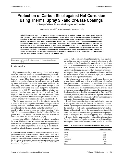
High-temperature alloys must have good mechanical properties and corrosion resistance and be relatively easy to manufacture. However, it is not likely for a single alloy to have all these properties. Most high temperature alloys are iron-, nickel-, or cobalt-base because these elements have high melting points and are easy to manufacture without problems. Unfortunately, their oxides are not protective enough in the combustion environment of a fossil-fuel power plant at temperatures above 550 °C. Nevertheless, addition of other elements to establish more protective oxides such as Cr2O3, Al2O3, or SiO2 has improved their corrosion resistance. These oxides offer protection due to their low growth rate and the effective barrier they provide against ionic migration (Ref 1-3). The threshold amount required in the alloy for the establishment of a continuous protective oxide layer depends on the alloying elements. Chromium affects the mechanical properties of the alloys the least, but a higher threshold value is required to allow a passive behavior against oxidation (16 to 20%). For aluminum additions, a threshold value of 15% is required (Ref 1, 2), whereas for silicon additions to steel the threshold value is the lowest, 5% (Ref 2, 4, 5). Although the addition of aluminum or silicon gives alloys the best oxidation and corrosion resistance because they form protective oxides with low growth rate, their incorporation can affect the mechanical properties of the alloy. It has been observed that a third element, normally chromium, which forms
机械类英文文献+翻译
机械类英文文献+翻译20.9 MACHINABILITYThe machinability of a material usually defined in terms of four factors:1、Surface finish and integrity of the machined part;2、Tool life obtained;3、Force and power requirements;4、Chip control.Thus, good machinability good surface finish and integrity, long tool life, and low force And power requirements. As for chip control, long and thin (stringy) cured chips, if not broken up, can severely interfere with the cutting operation by becoming entangled in the cutting zone.Because of the complex nature of cutting operations, it is difficult to establish relationships that quantitatively define the machinability of a material. In manufacturing plants, tool life and surface roughness are generally considered to be the most important factors in machinability. Although not used much any more, approximate machinability ratings are available in the example below.20.9.1 Machinability Of SteelsBecause steels are among the most important engineering materials (as noted in Chapter 5), their machinability has been studied extensively. The machinability of steels has been mainly improved by adding lead and sulfur to obtain so-called free-machining steels.Resulfurized and Rephosphorized steels. Sulfur in steels forms manganese sulfide inclusions (second-phase particles), which act as stress raisers in the primary shear zone. As a result, the chips produced break up easily and are small; this improves machinability. The size, shape, distribution, and concentration of these inclusions significantly influence machinability. Elements such as tellurium and selenium, which are both chemically similar to sulfur, act as inclusion modifiers in resulfurized steels.Phosphorus in steels has two major effects. It strengthens the ferrite, causingincreased hardness. Harder steels result in better chip formation and surface finish. Note that soft steels can be difficult to machine, with built-up edge formation and poor surface finish. The second effect is that increased hardness causes the formation of short chips instead of continuous stringy ones, thereby improving machinability.Leaded Steels. A high percentage of lead in steels solidifies at the tip of manganese sulfide inclusions. In non-resulfurized grades of steel, lead takes the form of dispersed fine particles. Lead is insoluble in iron, copper, and alumin um and their alloys. Because of its low shear strength, therefore, lead acts as a solid lubricant (Section 32.11) and is smeared over the tool-chip interface du ring cutting. This behavior has been verified by the presence of high concentra tions of lead on the tool-side face of chips when machining leaded steels.When the temperature is sufficiently high-for instance, at high cutting spee ds and feeds (Section 20.6)—the lead melts directly in front of the tool, acting as a liquid lubricant. In addition to this effect, lead lowers the shear stress in the primary shear zone, reducing cutting forces and power consumption. Lead can be used in every grade of steel, such as 10xx, 11xx, 12xx, 41xx, etc. Le aded steels are identified by the letter L between the second and third numeral s (for example, 10L45). (Note that in stainless steels, similar use of the letter L means 〝low carbon,〞a condition that improves their corrosion resistance.)However, because lead is a well-known toxin and a pollutant, there are se rious environmental concerns about its use in steels (estimated at 4500 tons of lead consumption every year in the production of steels). Consequently, there is a continuing trend toward eliminating the use of lead in steels (lead-free ste els). Bismuth and tin are now being investigated as possible substitutes for lea d in steels.Calcium-Deoxidized Steels. An important development is calcium-deoxidize d steels, in which oxide flakes of calcium silicates (CaSo) are formed. These f lakes, in turn, reduce the strength of the secondary shear zone, decreasing tool-chip interface and wear. Temperature is correspondingly reduced. Consequently, these steels produce less crater wear, especially at high cutting speeds.Stainless Steels. Austenitic (300 series) steels are generally difficult to mac hine. Chatter can be s problem, necessitating machine tools with high stiffness.However, ferritic stainless steels (also 300 series) have good machinability. M artensitic (400 series) steels are abrasive, tend to form a built-up edge, and req uire tool materials with high hot hardness and crater-wear resistance. Precipitati on-hardening stainless steels are strong and abrasive, requiring hard and abrasio n-resistant tool materials.The Effects of Other Elements in Steels on Machinability. The presence of aluminum and silicon in steels is always harmful because these elements com bine with oxygen to form aluminum oxide and silicates, which are hard and a brasive. These compounds increase tool wear and reduce machinability. It is es sential to produce and use clean steels.Carbon and manganese have various effects on the machinability of steels, depending on their composition. Plain low-carbon steels (less than 0.15% C) c an produce poor surface finish by forming a built-up edge. Cast steels are mor e abrasive, although their machinability is similar to that of wrought steels. To ol and die steels are very difficult to machine and usually require annealing pr ior to machining. Machinability of most steels is improved by cold working, w hich hardens the material and reduces the tendency for built-up edge formation.Other alloying elements, such as nickel, chromium, molybdenum, and vana dium, which improve the properties of steels, generally reduce machinability. T he effect of boron is negligible. Gaseous elements such as hydrogen and nitrog en can have particularly detrimental effects on the properties of steel. Oxygen has been shown to have a strong effect on the aspect ratio of the manganese sulfide inclusions; the higher the oxygen content, the lower the aspect ratio an d the higher the machinability.In selecting various elements to improve machinability, we should consider the possible detrimental effects of these elements on the properties and strengt h of the machined part in service. At elevated temperatures, for example, lead causes embrittlement of steels (liquid-metal embrittlement, hot shortness; see Se ction 1.4.3), although at room temperature it has no effect on mechanical prop erties.Sulfur can severely reduce the hot workability of steels, because of the fo rmation of iron sulfide, unless sufficient manganese is present to prevent suchformation. At room temperature, the mechanical properties of resulfurized steels depend on the orientation of the deformed manganese sulfide inclusions (aniso tropy). Rephosphorized steels are significantly less ductile, and are produced so lely to improve machinability.20.9.2 Machinability of Various Other MetalsAluminum is generally very easy to machine, although the softer grades te nd to form a built-up edge, resulting in poor surface finish. High cutting speed s, high rake angles, and high relief angles are recommended. Wrought aluminu m alloys with high silicon content and cast aluminum alloys may be abrasive; they require harder tool materials. Dimensional tolerance control may be a pro blem in machining aluminum, since it has a high thermal coefficient of expans ion and a relatively low elastic modulus.Beryllium is similar to cast irons. Because it is more abrasive and toxic, t hough, it requires machining in a controlled environment.Cast gray irons are generally machinable but are. Free carbides in castings reduce their machinability and cause tool chipping or fracture, necessitating to ols with high toughness. Nodular and malleable irons are machinable with hard tool materials.Cobalt-based alloys are abrasive and highly work-hardening. They require sharp, abrasion-resistant tool materials and low feeds and speeds.Wrought copper can be difficult to machine because of built-up edge form ation, although cast copper alloys are easy to machine. Brasses are easy to ma chine, especially with the addition pf lead (leaded free-machining brass). Bronz es are more difficult to machine than brass.Magnesium is very easy to machine, with good surface finish and prolong ed tool life. However care should be exercised because of its high rate of oxi dation and the danger of fire (the element is pyrophoric).Molybdenum is ductile and work-hardening, so it can produce poor surfac e finish. Sharp tools are necessary.Nickel-based alloys are work-hardening, abrasive, and strong at high tempe ratures. Their machinability is similar to that of stainless steels.Tantalum is very work-hardening, ductile, and soft. It produces a poor surf ace finish; tool wear is high.Titanium and its alloys have poor thermal conductivity (indeed, the lowest of all metals), causing significant temperature rise and built-up edge; they can be difficult to machine.Tungsten is brittle, strong, and very abrasive, so its machinability is low, although it greatly improves at elevated temperatures.Zirconium has good machinability. It requires a coolant-type cutting fluid, however, because of the explosion and fire.20.9.3 Machinability of Various MaterialsGraphite is abrasive; it requires hard, abrasion-resistant, sharp tools.Thermoplastics generally have low thermal conductivity, low elastic modul us, and low softening temperature. Consequently, machining them requires tools with positive rake angles (to reduce cutting forces), large relief angles, small depths of cut and feed, relatively high speeds, and proper support of the work piece. Tools should be sharp.External cooling of the cutting zone may be necessary to keep the chips f rom becoming 〝gummy〞and sticking to the tools. Cooling can usually be a chieved with a jet of air, vapor mist, or water-soluble oils. Residual stresses m ay develop during machining. To relieve these stresses, machined parts can be annealed for a period of time at temperatures ranging from to ( to ), and th en cooled slowly and uniformly to room temperature.Thermosetting plastics are brittle and sensitive to thermal gradients during cutting. Their machinability is generally similar to that of thermoplastics.Because of the fibers present, reinforced plastics are very abrasive and are difficult to machine. Fiber tearing, pulling, and edge delamination are significa nt problems; they can lead to severe reduction in the load-carrying capacity of the component. Furthermore, machining of these materials requires careful rem oval of machining debris to avoid contact with and inhaling of the fibers.The machinability of ceramics has improved steadily with the development of nanoceramics (Section 8.2.5) and with the selection of appropriate processi ng parameters, such as ductile-regime cutting (Section 22.4.2).Metal-matrix and ceramic-matrix composites can be difficult to machine, d epending on the properties of the individual components, i.e., reinforcing or wh iskers, as well as the matrix material.20.9.4 Thermally Assisted MachiningMetals and alloys that are difficult to machine at room temperature can be machined more easily at elevated temperatures. In thermally assisted machinin g (hot machining), the source of heat—a torch, induction coil, high-energy bea m (such as laser or electron beam), or plasma arc—is forces, (b) increased too l life, (c) use of inexpensive cutting-tool materials, (d) higher material-removal rates, and (e) reduced tendency for vibration and chatter.It may be difficult to heat and maintain a uniform temperature distribution within the workpiece. Also, the original microstructure of the workpiece may be adversely affected by elevated temperatures. Most applications of hot machi ning are in the turning of high-strength metals and alloys, although experiment s are in progress to machine ceramics such as silicon nitride.SUMMARYMachinability is usually defined in terms of surface finish, tool life, force and power requirements, and chip control. Machinability of materials depends n ot only on their intrinsic properties and microstructure, but also on proper sele ction and control of process variables.20.9 可机加工性一种材料的可机加工性通常以四种因素的方式定义:1、分的表面光洁性和表面完整性。
铸造术语 中英文对照
一、基本术语1。
铸造:casting ,founding ,foundry2.砂型铸造:Sand casting process3。
特种铸造:Special casting process4。
铸件: casting5。
毛坯铸件:Rough casting6.砂型铸件: Sand casting7.试制铸件:Pilot casting8。
铸态铸件:as—cast casting9。
铸型[型]:mold10。
铸造工艺:Casting process,foundry technology11。
铸造用材料: Foundry materials12。
铸造工艺材料:Consumable materials13。
铸造设备:Foundry equipment, foundry facilities14。
铸工: Caster,founder, foundry worker15.铸造工作者: foundryman16.铸造车间:Foundry shop17。
铸造厂:Foundry18.铸造分厂:Attached foundry,captive foundry,tied foundry19.铸造三废: Foundry affluent20。
一批: A batch21。
一炉: A cast, a heat,a melt22.铸焊:Cast welding, flow welding23。
铸锭:ingot二、铸造合金及熔炼、浇注2.1铸造合金基础术语1。
铸造合金:Cast alloy2。
共晶合金系:Eutectic alloy system3。
共晶合金:Eutectic alloy4。
亚共晶合金:Hypoeutectic alloy5。
过共晶合金: Hypereutectic alloy6。
共晶团: Eutectic cell7.共晶温度:Eutectic temperature8.共晶转变:Eutectic reaction,eutectic transformation 9。
机械设计制造及其自动化专业英语_Unit 08 Die Manufacture
word
• • • •
die [dai] n.;v.膜具;冲[模]切 forming [‘fɔ:miŋ] n. 成形(法),(成形)加工 copy milling 仿形铣制 electrodischarge machining (EDM) 放电 加工,电火花加工 • electrochemical machining (ECM) ) 电解 加工,电化学加工
手动车削或铣削是制造模具最古老的机械过 程。模具腔体通过金属去除技术直接加工成 模具钢块。
6
Manual (Conventional) Turning or Milling
Therefore, the die steel must be relatively soft to facilitate machining. Axisymmetric dies are easily made by turning on lathes.
2
Die Manufacture
word
• replica [ˈreplikə] n. 仿形,复制品,复型 • dielectric [ˌdaii‘lektrik] n.;a. 绝缘材料,电介 质;绝缘的 • punch [ˈpʌntʃ] n.;v. 冲头,穿孔器;冲孔 • HRC = Rockwell hardness • hub [hʌb] n. 冲头,切压母模,轮毂 • isothermal [ˌaisəu‘θə:məl] n.; a. 等温,等温 线;等温的
20
Elctrodischarge Machining (EDM)
The die block is mounted inside a tank containing a dielectric fluid, which is usually a hydrocarbon oil. The shaped metal or carbon electrode is lowered toward the die block under a servocontrol.
Cobalt-containing alloys
专利名称:Cobalt-containing alloys 发明人:Paul Crook申请号:US06/077825申请日:19790920公开号:US04353742A公开日:19821012专利内容由知识产权出版社提供摘要:A wear-resistant alloy, which excluding impurities, has the following composition: (a) about 50 to 70% of cobalt, nickel and iron; (b) 27 to 35% of chromium; (c) 5 to 15% of molybdenum and/or tungsten; (d) 0. 3 to 2. 25% of carbon and/or boron; (e) 0 to 3% of silicon and/or manganese; (f) 0 to 5% of one or more of titanium, hafnium, zirconium, vanadium, niobium, and tantalum; (g) 0 to 5% of copper, and (h) 0 to 5% of one or more of the following rare earths: lanthanum, cerium, yttrium, and thorium. The cobalt is the range 25 to 40%, and the nickel in the range 4 to 12%. There is from 0 to 7.5% of constituents (f), (g) and (h). The iron is present in a quantity not exceeding 25%. If there is 2% or more of carbon and/or boron, there is more than 30% chromium. (All percentages by weight) .A welding or surfacing consumable which (ignoring the effect of dilution by substrate) is capable of depositing such an alloy may also be made.申请人:CABOT STELLITE EUROPE LIMITED代理人:Jack Schuman,Robert F. Dropkin更多信息请下载全文后查看。
镍基(钴基)高温合金材料一览表
上海研发、生产与销售高温合金、耐蚀合金、精密合金等特殊合金材料的高新技术企业。
累积了丰富的冶炼、轧制、锻造、轧管的经验。
公司近几年来不断开发新产品、探索新技术、新工艺,并与国内多家科研院所合作研发,取得了丰厚的成果。
为多项国家级重点工程提供特种钢材料及配件。
公司从真空熔炼、电渣重熔、锻造加工、热处理到机加工全套生产线。
公司专业生产特殊合金材料,产品广泛应用于石油化工、电站脱硫、航空航天、舰船、机械、通讯电子等,为应用领域的高温、高压、腐蚀、磨损、疲劳、蠕变等使用环境,从材料角度提供科学的解决方案和优良的产品服务。
- 1、下载文档前请自行甄别文档内容的完整性,平台不提供额外的编辑、内容补充、找答案等附加服务。
- 2、"仅部分预览"的文档,不可在线预览部分如存在完整性等问题,可反馈申请退款(可完整预览的文档不适用该条件!)。
- 3、如文档侵犯您的权益,请联系客服反馈,我们会尽快为您处理(人工客服工作时间:9:00-18:30)。
DOI: 10.1126/science.1121738, 90 (2006);312 Science et al.J. Sato Cobalt-Base High-Temperature AlloysThis copy is for your personal, non-commercial use only.clicking here.colleagues, clients, or customers by , you can order high-quality copies for your If you wish to distribute this article to othershere.following the guidelines can be obtained by Permission to republish or repurpose articles or portions of articles): May 31, 2013 (this information is current as of The following resources related to this article are available online at/content/312/5770/90.full.html version of this article at:including high-resolution figures, can be found in the online Updated information and services, 35 article(s) on the ISI Web of Science cited by This article has been/cgi/collection/mat_sci Materials Sciencesubject collections:This article appears in the following registered trademark of AAAS.is a Science 2006 by the American Association for the Advancement of Science; all rights reserved. The title Copyright American Association for the Advancement of Science, 1200 New York Avenue NW, Washington, DC 20005. (print ISSN 0036-8075; online ISSN 1095-9203) is published weekly, except the last week in December, by the Science o n M a y 31, 2013w w w .s c i e n c e m a g .o r g D o w n l o a d e d f r o mCobalt-Base High-Temperature AlloysJ.Sato,T.Omori,K.Oikawa,I.Ohnuma,R.Kainuma,K.Ishida *We have identified cobalt-base superalloys showing a high-temperature strength greater than those of conventional nickel-base superalloys.The cobalt-base alloys are strengthened by a ternary compound with the L12structure,g ¶Co 3(Al,W),which precipitates in the disordered g face-centered cubic cobalt matrix with high coherency and with high melting points.We also identified a ternary compound,g ¶Ir 3(Al,W),with the L12structure,which suggests that the Co-Ir-Al-W–base systems with g þg ¶(Co,Ir)3(Al,W)structures offer great promise as candidates for next-generation high-temperature materials.Cobalt and nickel have the face-centered cubic (fcc)structure at high tempera-ture,with melting points of 1768and 1728K,respectively.However,the most fas-cinating heat-resistant alloys are the Ni-base superalloys,which are used,for example,in aircraft engines,industrial gas turbines,reac-tors,and the chemical industry (1).The main reason why Co-base alloys have not found widespread usage is their lower strength compared with that of Ni-base alloys,but they have been studied for a long time (2).With the development of Ni-base superalloys strengthened by the ordered g ¶Ni 3(Al,Ti)phase,the possibilities of precipitation hard-ening using geometrically close-packed pha-ses that have the form of A 3B have been extensively investigated.Two types of geo-metrically close-packed phases have been reported in Co-base alloys:Co 3Ti with the L12structure (3,4)and ordered fcc Co 3Ta (5,6).Although the effect of various alloy-ing elements on the stability and morphology of the g ¶Co 3Ti phase has been investigated,the usefulness of the g ¶phase is restricted to temperatures below 1023K (4).In the case of Co 3Ta,the ordered fcc phase is metastable and readily converts to the stable hexagonal close-packed (hcp)structure Co 3Ta (6).Fur-thermore,the lattice parameter mismatches of these phases in Co-base alloys are usually more than 1.0%,which is not as useful for strength-ening as the geometrically close-packed phases in Ni-base superalloys,where mismatches typically vary from –0.1to þ0.5%(2).Ge-ometrically close-packed phase strengthening has thus not been used in commercial Co-base superalloys.In determining the phase diagram of the Co-Al-W ternary system,we found a stable ternary compound with the L12structure,which has the form Co 3(Al,W),designated as g ¶.Figure 1A shows a transmission elec-tron micrograph of Co-9Al-7.5W (atomic %)annealed at 1173K for 72hours after solution treatment at 1573K for 2hours.The cuboidalphase homogeneously precipitates in the g (A1)matrix,which is very similar to the morphology observed in Ni-base superalloys.The selected area electron diffraction pattern of the same sample is also shown in Fig.1B,where the crystal structure of the g ¶phase is confirmed as being the L12ordered structure and the cuboidal g ¶precipitates align along the G 0019directions.The compositions of the matrix and that of the precipitate were de-termined using a field emission electron probe microanalyzer (FE-EPMA).The composition of cuboidal precipitates observed in Fig.1A is the ternary compound Co 3(Al,W),where the composition of Al and W has an almost equiatomic ratio.In the geometrically close-packed A 3B compound,the stable Co 3Wphase with the DO 19structure appears in the Co-W binary system (7).Although no stable compound of Co 3Al is formed in the Co-Al binary system,the formation of an ordered Co 3Al phase has been reported (8,9).Recently,the metastable Co 3Al phase with the L12structure,which is formed in the Co-14Al alloy annealed at 873K for 24hours,was observed by our group (10).It can be said,therefore,that metastable Co 3Al g ¶is stabilized by alloying with W.Ternary compounds of Co 3(Al,Cr)or Co 3(Al,Mo)have not been reported.Figure 2,A and B,show isothermal sec-tion diagrams determined experimentally in the present study,as well as recent data (11)on the Co-W binary system at 1173and 1273K,respectively.The g ¶phase is stable at 1173K but metastable at 1273K.The thermal stability of the g ¶phase and the effect of alloying were investigated by differential scanning calorime-try (DSC).Figure 3A shows the DSC curves on heating,where the solvus temperature was determined from the endothermic peak,as indi-cated by arrows.The DSC curve of Waspaloy E Ni-21Cr-2.5Mo-13Co-2.9Al-3.5Ti-0.3C (atomic %)^,a widely used commercial Ni-base superalloy,is also shown.The solvus temperatures of the g ¶phase in the Co-Al-W ternary system is È1263K,which corresponds well with the phase diagram,as shown in Fig.2.The addition of Ta stabilizes the g ¶phase such that the solvus temperature is È1373K,and this value is higher than that of Waspaloy.Department of Materials Science,Graduate School of Engineering,Tohoku University,Sendai 980-8579,Japan.*To whom correspondence should be addressed.E-mail:ishida@material.tohoku.ac.jpFig. 1.Electron micrographs of Co-9Al-7.5W alloy annealed at 1173K for 72hours.(A )Dark-field image.(B )Selected area diffraction pat-tern.(C and D )Field emission scanning electron micrographs of Co-8.8Al-9.8W-2Ta (C)and Co-8.8Al-9.8W-2Mo (D)annealed at 1273K for 1week.at.%WAat.%WB Fig.2.Isothermal section diagrams of the Co-Al-W ternary system in the Co-rich portion at (A )1173K and (B )1273K.7APRIL 2006VOL 312SCIENCE90REPORTSo n M a y 31, 2013w w w .s c i e n c e m a g .o r g D o w n l o a d e d f r o mThe addition of Nb or Ti shows a similar effect.It can also be seen from Fig.3A that the melting temperatures of Co-Al-W–base alloys are È1673K,which is 50to 100K higher than those of Ni-base superalloys (12).Figure 3B shows the temperature variation of Vickers hardness of the g þg ¶structure for Co-9.2Al-9W and Co-8.8Al-9.8W-2Ta aged at 1073K for 24hours after solution treatment at 1573K for 2hours.Aging treatment of Waspaloy was carried out at 1118K for 24hours and 1033K for 16hours after solution treatment at 1353K for 4hours.The hardness of the g þg ¶structure of the Co-9.2Al-9W alloy is very similar to that of Waspaloy.The addition of Ta increases the hardness,which might be due to the stabilization of the g ¶phase up to 1373K.The 0.2%compressive proof strengths of Co-9.2Al-9W and Co-8.8Al-9.8W-2Ta alloys are 473and 674MPa at 1143K,respectively,as compared with 520MPa for the 0.2%tensile proof strength of Waspaloy (12).These data correspond well with the results for high-temperature hardness in Fig.3B.Semiquantitative analyses of the partition behavior of various alloying elements be-tween the g and g ¶phase were also carried out by EPMA.The results show that Mo,Ti,Nb,V,and Ta distribute to the g ¶phase rather than the g phase and stabilize the g ¶phase,whereas Fe,Mn,and Cr tend to distribute to the g phase,which is similar to the case of Ni-base superalloys (13,14).It is notable thatNi is almost equally distributed in the g and g ¶phases and substitutes for more than 50%of the Co with the rise in the solvus temperature of the g ¶phase.For instance,the g ¶solvus temperature of Co-20Ni-10Al-10W-2Ta is È1423K.Because the partition coefficient between the g and g ¶phases depends on the composition and temperature,as in the case of Ni-base superalloys (13),more systematic studies are required.The lattice parameters of the g and g ¶phases of Co-9.2Al-9W alloy heat-treated at 1173K were determined by room tempera-ture x-ray diffraction at 0.3580and 0.3599nm,respectively.The lattice parameter mismatch is thus 0.53%,which is similar to that of Ni-base superalloys.The lattice parameter mismatch affects the morphology of the pre-cipitate,because the mismatch is the driving force in the growth and coalescence of g ¶par-ticles.Figure 1,C and D,show field emis-sion electron scanning micrographs of a typical g þg ¶structure of Co-8.8Al-9.8W–base alloy annealed at 1273K,where the addition of 2atomic %Ta and Mo changes the morphol-ogy and the volume fraction of the g ¶phase.The volume fraction of the g ¶phase is in-creased by the addition of Ta,which is due to the increase in solvus temperature,as shown in Fig.3.The spherical g ¶phase shown in Fig.1D suggests that the g /g ¶interface is coherent and stable.These findings suggest that the alloy design of Co-Al-W–base super-alloys can be achieved under a wide variety of conditions,as is the case for the Ni-base superalloys.The present Co-Al-W alloys exhibit very good hot workability.Because the melting tem-peratures of Co-Al-W–base alloys are higher than those of conventional Ni-base super-alloys (Fig.3),hot-working could be carried out in a wider temperature range than was possible in the Ni-base alloys,although new Ru-containing nickel superalloys with higher melting temperatures have been reported (15).The g þg ¶structure also shows good me-chanical properties at room temperature.The tensile properties of Co-9.2Al-9W heat-treated at 1173K for 1hour after hot-rolling are as follows:0.2%proof and tensile strengths of 737and 1090MPa,respectively,with 20%elongation;these are comparable with the tensile properties of Ni-base superalloys such as Waspaloy,with 0.2%proof and tensile strengths of 795and 1275MPa,respectively,and 25%elongation (12).We note a ternary compound,g ¶Ir 3(Al,W),with the L12structure.Figure 4shows the electron micrograph of a dark-field image and the selected area diffraction pattern of Ir-10Al-10W alloy annealed at 1573K for 72hours,which confirms that the g ¶phase with the L12structure finely precipitates.The high-temperature hardness of Ir-10Al-10W and Ir-20Co-10Al-10W alloys annealed at 1573K for 24hours is shown in Fig.3B,where high hardness is maintained even at 1273K.Because Ir has a melting tem-perature of 2720K and the fcc g phase in the Co-Ir binary system shows a complete solid solution,the Ir-Al-W and Co-Ir-Al-W–base systems with g þg ¶(Co,Ir)3(Al,W)structures offer great promise as candidates for next-generation high-temperature ma-terials (16).References and Notes1.R.F.Decker,C.T.Sims,in The Superalloys ,C.T.Sims,W.C.Hagel,Eds.(Wiley,New York,1972),pp.33–77.2. C.T.Sims,in The Superalloys ,C.T.Sims,W.C.Hagel,Eds.(Wiley,New York,1972),pp.145–174.3.J.M.Blaise,P.Viatour,J.M.Drapier,Cobalt 49,192(1970).4.P.Viatour,J.M.Drapier,D.Coutsouradis,Cobalt 3,67(1973).5.J.M.Drapier,J.L.de Brouwer,D.Coutsouradis,Cobalt 27,59(1965).6.J.M.Drapier,D.Coutsouradis,Cobalt 39,63(1968).7.S.V.Nagender Naidu,A.M.Sriramamurthy,P.Rama Rao,in Binary Alloy Phase Diagrams ,T.B.Massalski et al .,Eds.(ASM International,ed.2,1970),pp.1257–1259.8. A.J.Bradley,G.C.Seager,J.Inst.Met.64,81(1939).9.O.S.Edwards,J.Inst.Met.67,67(1941).10.T.Omori,Y.Sutou,K.Oikawa,K.Kainuma,K.Ishida,paper presented at International Conference on Martensitic Transformation (ICOMAT)05,Beijing (2005).11.J.Sato,K.Oikawa,R.Kainuma,K.Ishida,Mater.Trans.46,1199(2005).12.N.S.Stoloff,in Metals Handbook (ASM International,ed.10,1990),vol.1,pp.950–980.13. C.C.Jia,K.Ishida,T.Nishizawa,Metall.Mater.Trans.A25A ,473(1994).14. A.Volek,F.Pyczak,R.F.Singer,H.Mughrabi,ScriptaMater.52,141(2005).15.Q.Feng,T.K.Nandy,S.Tin,T.M.Pollock,Acta Mater.51,269(2003).16.Y.Yamabe-Mitarai,Y.Gu,C.Huang,R.Vo ¨lkl,H.Harada,JOM 56,34(2004).17.This work was supported by Core Research for EvolutionalScience and Technology and the Japan Science and Technology Agency.We thank JEOL Ltd.for the use of their FE-EPMA.24October 2005;accepted 6March 200610.1126/science.1121738A9001100130015001700Temperature (K)Temperature (K)30050070090011001300200400600H v800BFig.3.(A )DSC curves.(Top)Co-8.8Al-9.8W-2Ta;(middle)Waspaloy;(bottom)Co-9.2Al-9W.(B )High-temperature Vickers hardness.())Ir-20Co-10Al-10W,(þ)Ir-10Al-10W,(*)Co-9.2Al-9W,(r )Co-8.8Al-9.8W-2Ta,(g )Waspaloy.Fig.4.Electron micrographs of Ir-10Al-10W alloy annealed at 1573K for 72hours.(A )Dark-field image.(B )Selected area diffraction pattern.REPORTS SCIENCEVOL 3127APRIL 200691o n M a y 31, 2013w w w .s c i e n c e m a g .o r g D o w n l o a d e d f r o m。