扬修电动头2SA8说明书
SuperEvac PLUS II 电动豁除机操作和维护指南说明书

SuperEvac™ PLUS II Vacuum PumpOperation and MaintenanceManualModels: 9371x 9374x, 9376x, 9378x, 9379xPN #143060_RevBTabl e of Cont e nts PageImportant Notices to PurchaserWarningFeatures of Your New Pump...................................................................................3The Purpose of the SuperEvac ™ PLUS II Design......................................................4Important Steps of Initial Start-up...........................................................................5Vacuum Tips for Best Performance.........................................................................5-6Dual Voltage Motor Power Conversion....................................................................6Basic Troubleshooting............................................................................................7• Four Most Common Problems • Oil Leakage• The Steps to Solving 95% of All ProblemsDiagnostic Chart....................................................................................................8, 9Replacement Parts................................................................................................10, 11Warranty and Service.. (12)Check for damage immediately.Prior to shipment, all YELLOW JACKET ® SuperEvac ™ PLUS II vacuum pumps are completely tested and inspected to assure compliance with Ritchie Engineering factory specifications.If the pump carton is damaged, check contents immediately. Note damage on shipper’s Bill of Lading and have shipper sign your statement. Notify the carrier immediately of the damage to arrange inspection of the pump and packaging.The CARRIER ALONE is responsible forhandling and settling your claim. Ritchie Engineering will cooperate in assessing damage if the pump is returned to the factory prepaid.CARTON CONTENTS INCLUDE:• SuperEvac ™ PLUS II Pump• Bottle of YELLOW JACKET ® SuperEvac ™ Pump Oil• Shoulder Strap• Locking, Removable Power Cord • Owner’s Manual• This unit generates a deep vacuum that can be harmful to human tissue. Do not expose any part of the human body to the vacuum.• Do not operate this unit with the exhaust blocked or restricted. Remove red shipping cap prior to use.• Keep unit a minimum of 4” (10 cm) from objects to provide adequate cooling of motor.• Continuous sound pressure level of this unit can exceed 70dB (A).• Wear goggles and protective clothing when using this product.• Designed for use with A2L systems.• This unit is only rated as non-sparking. Not intended for use in Zone 0 or Zone 1 hazard areas.Warranty is void if the set vacuum pump voltage does not match the power supply.1. Male flare pump intake. Tethered cap stays with unit. Large diameter hose suggested for maximum pull down.2. Additional intake ports.3. Vacuum gauge shows evacuation progress down to 30” range, so you will know when to turn on electronic gaugefor more precise reading.4. Gas ballast valve (not shown) helps remove moisture and other con d ensable vapors that have been drawn into the pump as a result of evacuation.5. Opening the ballast allows fresh air to enter the cartridge and keep vapors from combining with the oil. Vaporsescape harmlessly through the exhaust valve. If combined with oil, vapors canturn the oil milky white and lower pump performance below specifica t ions. 6. To operate ballast, turn the valve counter-clockwise one full turn afterevacuation starts. As the vacuum reading reaches 1000-2000 microns, close the ballast to achieve a higher vacuum range.Features of Your New PumpLight weight universal BLDC motor can run on voltage as low as 85 volts with no issue, and draws fewer amps than AC motors.Large, Impact-Resistant, Toughened Nylon Feet Reduces vibration and increases durability and longevityHelps pump run cool and increases performanceCooling FinsQuick indication of evacuation progress and quickly spot if system is leakingVacuum Indicator Gauge For well-balanced carrying and liftingHeavy-Duty Steel HandleIncludes 3/4" garden hose thread to easily vent exhaust to remote locationWide-Mouth Oil Reservoir Port For better view of oil leveland oil conditionElongated Sight Glass For convenient, fast oil changes 3/8" Brass Oil DrainPlug Tether For easy carrying over long distancesConvenient Shoulder Strap EyeletsFor easily lifting onto roofsRope Loop Helps remove contaminants usually trapped in sump with other designsDownward Angled Sump So oil plug stays with machineFor oil changes without losing system vacuumIsolation Valve For flexibility in evacuationsMultiple Intake Fittings For a long lifeLight-Weight BLDC Motor NON-Sparking Switch with Locking IEC Connector For use with A2L systemsThe SuperEvac ™ PLUS II pump is a 2-stage ro t ary vane design (at right) that increases efficiency and speeds pump down to 15 microns.The pump lowers the internal pressure of a refrigeration system until moisture boils into a vapor. As the moisture is vaporized, it is evacuated by the pump to help dehy-drate the system. Most technicians try to achieve between 250 and 1000 microns.A manometer or electronic vacuum gauge are the only ways to monitor evacua-tion progress. Manometer readings are approximate in inches of mercury. Only an electronic vacuum gauge (see page 8) isaccurate enough to show when you reach the desired mi c ron range.As the chart shows, only an electronic gauge reads fine differences to provide assurance that the vacuum is low enough to boil the greatest possible amount ofmoisture.The Purpose of the SuperEvac ™ PLUS II DesignHow one small drop dampens your profits.A small drop of moisture can hurt yourprofits and reputation.During new system set-up, protective caps are removed admitting moisture and air into system components.First stage exhausts into the intake of the second stagesimilar to two single stage pumps connected together. If air – a non-condensable – remains in thesystem, it collects on the high side reduc-ing system efficiency. This causes a risein head pressure. The discharge valve gets hotter than normal and organic solids form causing compressor failure. Moisture in the system can form ice which closes off openings in expansion valves and cap tubes, and prevent adequate cooling. Ultimately moisture and air can produceacids and sludge which could cause in -warranty failures.During service and parts replacement, the same contaminants get in again, and you could be called back for repairs by a dissatisfied customer.Moisture and air can even enter through system leaks. And as the moisture in the air increases, so does the amount of contamination. The higher the humidity, the bigger your problem.A vacuum pump “pulls” air and moisture out of the system before the system isdamaged. The higher and more complete the vacuum, the more moisture is removed. That’s why your SuperEvac ™PLUS II pump is specifically engineered forhigh vacuums of 15 microns and better.Vacuum Tips for Best Performance1. Make sure motor is off and the voltage selector switch is set to the appropriate voltage.2. Remove oil fill cap on pump cover. Fill with YELLOW JACKET ® SuperEvac ™ Pump Oil until oil level is even with oil level line.3. Make sure blank-off valve is in the open position (vertical). Stay clear of the oil fill/exhaust port! Remove intake cap to open intake to the atmosphere and then switch on the motor. When pump reaches running speed, replace cap. The vacuum indicator gauge should read 30 inches.4. To check the pump’s performance, attach a micron gauge to the 1/4” male flare fitting, making sure that the intake fitting is capped and the gas ballast valve is closed. Turn on the pump. The micron gauge will display the ultimate vacuum reached.5. Improve cold weather starting by opening intake and running your pump for 60 seconds...motor has cold weath-er soft-start mode and may take up to 60 seconds for temperatures 0c and below.6. When turning pump off, open intake fitting until vacuum indicator gauge reads zero to break vacuum just prior to shut-off.7. Disconnect pump and put cap on intake to keep out contaminants.8. If an extension cord is needed, refer to the below chart for proper sizing.6. Use the 4-in-1 Vacuum/Charge Valve & Core Tool (Part #18975) to remove the Schradervalves from the system and evacuate through unrestricted lines for a faster and higher vacuum.Removing Schraders saves over 30% in time.7. Use two pumps on very large systemsto reduce vacuum time. Put one of the pumps on the low side of the systemand one pump on the high side of the system.1. F or the fastest vacuum, connect your pump directly to the system. Going through a manifold slows the job.2. Use as large a hose as possible, eventhough the system has 1/4” fittings. A1/2” or 3/8” hose allows a much fasterand more complete vacuum.3. Use as short a hose as practical to get maximum evacuation speed. Short hoses make evacuation faster thanlonger hoses. Long hoses slow the process.4. Metal hoses are the most impervious so will be most effective in evacuation.5. Evacuate through both high and low sides at the same time to speed evacu-ation.Quick Tips:Important Steps of Initial Start-UpRECOMMENDED EXTENSIONCORD SIZESSTEP 1Disconnect power from motor. Unscrew voltage switch cover.STEP 2Remove cover, use screwdriver to switch to appropri-ate voltage setting.115=100-120vac 50/60 hz 230=230-240 vac 50/60 hzIf you think there is excessive mois-ture, blow out the AC&R system with dry nitrogen wherever possible. This reduces the amount of contaminants that must be “pulled” into the pump and increases evacuation e a nitrogen regulator valve with pressure limited to 150 psi and a frangible disc device set at 175 PSIG.When the indicator reaches the 29-30” range, turn on the electronic microngauge for more precise readings.Oil Changes: CHANGE OIL AFTER EACH USAGE to protect pump components from contaminants pulled into pump during service. Place used oil in a sealable container and dispose properly in accor-dance with local regulations.STEP 3Replace cover and screw down by hand. Do not use drill as cover could crack.CAUTION• Always remove cord before changing voltage.• Incorrect voltage setting can result in destruction of controller electronics, rendering motor inoperable.• To maintain IP X2 rating, replace switch cover to keep water out of controller.• Over-tightening screw could result in cracked cover.8. Use a SuperEvac System I, II or III to decrease vacuum time by over 50%. These systems include a 2-valve vacuum manifold and two 3/8”vacuum hoses which can evacuate three times faster than a 1/4” hose.9. Use a heat gun on the condenser and evaporator to speed the evacuation process.Built-in Vacuum Gauge: The built-in indicator gauge in your pump monitors evacuation progress down to the29-30” range. If thereading stays in the mid range, there is either high contamination or a large leakin the system.Gross Leak Dual Voltage Motor Power Conversion (if applicable)Turn onElectronic Gauge Warranty is void if the set vacuum pump voltage does not match the power supply.Basic Troubleshooting1. “Will not pump.” This usually means the pump will not pull a high enoughvacuum. This can be caused by valve being left open, missing O-rings under caps or contaminated oil.SUGGESTION: Change valve andO-rings change oil twice and recheck vacuum. 2. “Will not pull below 1000 microns.”SUGGESTION: Check for O-rings. Test pump to determine actual pull down. Remove all hoses and connect vacuum sensor directly to pump.3. “Noisy.” Pumps are noisy when theyhave not achieved a high vacuum. Inintermediate vacuum, there will be oil,vane and exhaust noises.SUGGESTION: Listen to the pump athigh vacuum. If relatively quiet, the pump is running properly. If still noisy,there may be a system leak.4. “Repair and return.” This is the most difficult return comment to handle, since we are unsure of what needs to be done to keep the customer satisfied.SUGGESTION: Be specific about the problem with your pump if returning it.Starting Pro bl ems• Be sure pump is plugged into live receptacle with line voltage plus or minus 10% of voltage on motor name-plate. Long extension cords can greatly reduce voltage and cause problems.• Pump/oil temp. must be 30°F (-1°C) or higher. Open intake to atmosphere and switch on pump; run up to speed before connecting to system.Four Most Common Comments on Pump Return Paperwork:• Your SuperEvac ™ PLUS II pump features a heavy-duty high torque motor for cold weather starting, but dirty oil makesstarting more difficult, causing unnec-essary wear on your unit.• Dropping your pump can damage it. In a locked pump condition, motor will not run and the thermal overload will kickout.• Disconnect power cord and set pump with front cover face down on table.Reach into coupling area and try to rotate the coupling. Do not use pliers.if the pump does not rotate, it is "locked up."Oil Leakage• I f leak develops between front andrear half of oil case, tighten all screws.Replace gasket if necessary.• If shaft seal leaks, replace it.• Wipe pump dry and watch for source ofleak. Tighten screws and repair.The Steps to Solving 95% of All Problems1. Check oil level when pump is running. It should be between the indicated levels.2. Check vacuum pump. Connect micron gauge directly to the 1/4” port and cap intake port. Turn on pump, open the valve and check vacuum reading. If reading is good, check the system for leaks. OR, if testing a system, isolate pump with blank-off valve and get vacuum reading from the pump alone. If the pump does not pull and stay at a poor vacuum level, run until hot and change oil.3. Check all flare connections. Make sure they are tight.SuperEvac ™ Digital Vacuum GaugesThe SuperEvac ™ LCD Vacuum Gauge is a portable, lightweight, solid state instrument that indicates the vacuum pressure in the system using thermocouple technology. This is important because you need to know the vacuum to confirm moisture removal. The battery powered gauge measures atmospheric pressures of 760,000 to 1 micron in easy to read 1/2” high numbers (Part #69075).Diagnostics ChartThe YELLOW JACKET ® OMNI ™ Digital Vacuum Gauge is an easy-to-use, compact vacuum gauge that is loaded with features for the price. Easily set target vacuum level and the OMNI ™ and will give audio and visual signals when that level is reached. The easy-to-clean vacuum sensor handles 450 psi positive pressure and reads several units of vacuum (microns, millibar, Torr, and Pascal) (Part #69020).Diagnostics Chart continuedReplacement PartsDamaged supply cords must be replaced by special assemblies available from the manufacturer or its distributors Vacuum Pump Weights9374x9376x9378x9379x24.6 lbs. (11.2 kg)25.9 lbs. (11.7 kg)26.8 lbs. (12.2 kg)28.4 lbs. (12.9 kg)1112WARRANTY INFORMATIONRitchie Engineering guarantees YELLOW JACKET ® products to be free of defective material and workmanship which could affect the life of the product when used for the purpose for which it was designed. This warranty does not cover items that have been altered, abused (including failure to use the correct type of vacuum pump oil) or returned solely in need of field service maintenance.If found defective, we will either replace or repair at our option products within warranty period. Returns must be prepaid.Warranty does not cover use of lithium bromide, ammonia or leak stop type products.See to register your product or contact Customer Service for full warranty details.How to Obtain ServiceMost returned pumps are merely in need of normal field service maintenance, such as changing oil or making minor adjustments. In many instances, the troubleshooting information in this manual can save you the time and effort of returning your pump. When the information contained in this manual, however, does not solve the problem, please call for service.Contact the Ritchie Engineering Customer Service Department:Phone: (952) 943-1333 or (800) 769-8370Fax: (952) 943-1605 or(800) 322-8684E-mail:*************************You will receive personal help to determine if the problem can be solved without sending your pump to the factory and taking it out of service.Ritchie Engineering Company, Inc.YELLOW JACKET ® Products Division 10950 Hampshire Avenue South Bloomington, MN 55438-2623 USA E-mail:*************************Website: Phone: (800) 769-8370 (952) 943-1333 INT’L Fax: (800) 322-8684(952) 943-1605 INT’L©2020 Ritchie Engineering Company, Inc. Printed in the USA PN #143060_RevBWarranty is void if the set vacuum pump voltage does not match the power supply.。
SA-ZY-2×80Z 智能化液压张力机 使用说明书

甘肃诚信电力机具制造有限责任公司
图一 SA-ZY-2×80Z 张力机
图二 SA-ZY-2×80Z 张力机
目录
1. 概述..............................................................................................................................1 2. 性能参数......................................................................................................................3
2.1. 性能参数............................................................................................................ 3 2.2. 性能说明............................................................................................................ 4 2.3. 油位控制............................................................................................................ 5 2.4. 显示器使用说明................................................................................................ 6 3. 张力机操作............................................................................................................... 11 3.1. 主要控制元件说明.......................................................................................... 11 3.2. 张力机启动和停机.......................................................................................... 15 3.3. 张力机固定...................................................................................................... 16 3.4. 张力工况时的操作.......................................................................................... 17 3.5. 主动工况(牵引或送线)时的操作.............................................................. 19 3.6. 并轮牵引或放线.............................................................................................. 22 3.7. 牵引或送线、张力的操作.............................................................................. 23 3.8. 前支腿及夹紧油缸的使用.............................................................................. 23 3.9. 液压系统油温控制.......................................................................................... 24 3.10. 故障显示.......................................................................................................... 27 3.11. 张力机运输...................................................................................................... 27 4. 张力机保养............................................................................................................... 28 4.1. 柴油机保养...................................................................................................... 28 4.2. 机械传动部分的保养...................................................................................... 28
宝工 PT-32030D工业级电动螺丝刀(半自动) 说明书
PT-32030D 电动螺丝刀使用说明书感谢惠顾 感谢你使用电动螺丝刀. 本系列产品结构合理,质量精良, 运转精准, 使用方便. 为了能使本机发挥最大的使用效能, 操作前, 请仔细阅读本使用说明书, 阅读后请妥为保管收存, 以备日后查阅.警告! 为降低伤害风险,用户必须阅读 使用手册。
外型图(产品示意图,以实际为准,本公司持变更的权利) 用途本系列电动螺丝刀是适合空调、办公通讯、仪器仪表、电动工具等各类行业,以及电子行业为笔记本计算机、液晶显示器、手机等小家电行业快速装卸螺丝的专用工具。
特点* 采用无极调速电源供电,工作可靠稳定,节能环保。
* 全塑手柄,符合人体工学设计,使用便利。
* 具备扭力设定抵达自动停机功能,能有效保护螺丝及提高作业效率. 确保工件无损伤,外观完整。
* 内部采用优质电机、长寿命开关,运转噪音低,使用寿命长。
使用方法* 将电源线插头插入配套电源适配器的输出插孔内。
* 推压接头轴环,可装卸批头。
* 将电源适配器的插头接通电源插座。
* 调整拨动正反开关,向上推为反转,向下推为正转,中间为关断。
* 扭力调节套可调节扭力大小,顺时针扭力加大,逆时针扭力减小,参考扭矩标尺进行设定。
* 电源器的转速开关可进行无级调整速度。
* 按下压杆即可工作。
* 挂钩用于平衡器悬挂。
接头轴环特性附属品* 说明书 1份 * 批头 2只* 电源适配器(含电线) 1个注意事项* 本电动螺丝刀必须与随机的专用电源器配套使用。
* 请选用合格批头,以免作业时跳动过大。
* 经常检查电源线,发现破损,即刻停用。
* 运行中不得变换旋转方向,否则会造成电机及器件损坏,影响使用寿命。
* 本电动螺丝刀禁止在粉尘或潮湿环境中使用。
* 当产品出现故障时,请勿拆卸,请专业人员维修。
* 不要用气溶胶油或类似对的润滑剂来润滑工具,否则会导致产品异常。
* 不要敲击,跌落或滥用产品,否则可能导致裂纹或破损等问题。
* 不要使用化学试剂擦拭机壳。
PS07216 3 8 英寸电动扭头说明书

PS072163/8 Inch Electric DrillAssembly & Operating InstructionsREAD ALL INSTRUCTIONS AND WARNINGS BEFORE USING THIS PRODUCT.This manual provides important information on proper operation & maintenance. Every effort has beenmade to ensure the accuracy of this manual. These instructions are not meant to cover every possible condition and situation that may occur. We reserve the right to change this product at any time withoutprior notice.IF THERE IS ANY QUESTION ABOUT A CONDITION BEING SAFE OR UNSAFE, DONOT OPERATE THIS PRODUCT!HAVE QUESTIONS OR PROBLEMS? DO NOT RETURN THIS PRODUCT TO THE RETAILER - CONTACT CUSTOMER SERVICE.If you experience a problem or need parts for this product, visit our website or call our customer help line at 1-636-532-9888, Monday-Friday, 8 AM - 4 PM Central Time. A copy of the sales receipt is required.FOR CONSUMER USE ONLY – NOT FOR PROFESSIONAL USE.GENERAL SAFETY RULES FOR ALL ELECTRIC POWER TOOLSREAD AND UNDERSTAND ALL INSTRUCTIONS. Failure to follow all instructions listed below may result in electric shock, fire and/or serious personal injury.RECOGNIZE SAFETY SYMBOLS, WORDS AND LABELSWhat You Need to Know About Safety InstructionsWarning and Important Safety Instructions appearing in this manual are not meant to cover all possible conditions and situations that may occur. Common sense, caution and care must be exercised when operating or cleaning tools and equipment.Always contact your dealer, distributor, service agent or manufacturer about problems or conditions you do not understand.This is the safety alert symbol. It is used to alert you to potential personal injury hazards. Obey all safety messages that follow this symbol to avoid possible injury or death.DANGER indicates an imminently hazardous situation which, if not avoided, will result in death or serious injury.WARNING indicates a potentially hazardous situation which, if not avoided, could result in death or serious injury.CAUTION indicates a potentially hazardous situation which, if not avoided, may result in minor or moderate injury.CAUTION used without the safety alert symbol indicates a potentially hazardous situation which, if not avoided, may result in property damage.NOTE provides additional information that is useful for proper use and maintenance for this tool. If a NOTE is indicated make sure it is fully understood.IMPORTANT SAFETY INSTRUCTIONSWORK AREAKeep your work area clean and well lit. Cluttered work benches and dark work areas may cause accidents or injury.Do not operate power tools in explosive areas, such as in the presence of flammable liquids, gases or dust. Power tools create sparks which may ignite the dust or fumes.Keep bystanders, children and visitors away while operating a power tool. Distractions can cause you to lose control.ELECTRICAL SAFETYDouble insulated tools are equipped with a polarized plug (one blade is wider than the other.) This plug will fit in a polarized outlet only one way. If the plug does not fit fully in the outlet, reverse the plug. If it still does not fit, contact a qualified electrician to install a polarized outlet. Do not change the plug in any way. Double insulation eliminates the need for the three wire grounded power cord and grounded power supply system.Avoid body contact with grounded surfaces such as pipes, radiators, ranges and refrigerators. There is an increased risk of electric shock if your body is grounded.Do not abuse the cord. Never use the cord to carry the tool or pull the plug from an outlet. Keep the cord away from heat, oil, sharp edges, or moving parts. Replace damaged cords immediately. Damaged cords increase the riskof electric shock.When operating the tool outside, use an outdoor extension cord marked “WA” or “W.” These cords are rated for outdoor use and reduce the risk of electric shock. Make sure the extension cord being used is in good condition. If there are any cuts or nicks (no matter how deep) in the insulation, DO NOT use that cord. Also, make sure the extension cord is heavy enough to carry the current needed. DO NOT use small "around-the-house” lamp extension cords. These cords can easily overheat and/or catch fire when used with power tools.TOOL USE & CAREUse clamps or other practical ways to secure and support the workpiece to a stable platform. Holding the work by hand or against your body is unstable and may lead to loss of control.Do not force tool. Use the correct tool for your application. The correct tool will do the job better and safer at the rate for which it is designed.Do not use the tool if the power switch does not turn it “ON” or “OFF”. Any tool that cannot be controlled with the switch is dangerous and must be repaired.Disconnect the power cord plug from the power source before making any adjustments, changing accessories or storing the tool. Such preventive safety measures reduce the risk of starting the tool accidentally.Store idle tools out of reach of children and other untrained persons. Tools are dangerous in the hands of untrained users.People with pacemakers or other electronic devices should consult with a physician before operating this product. Interruption or failure of the pacemaker could occur when electrical equipment is operated within close proximity of electrical devices.Inhaling dust created as a result of construction projects could be hazardous to your health. Construction dust may contain chemicals, which are known to cause cancer, birth defects and other reproductive harm in the State of California.These chemicals could be, but are not limited to: lead from lead based paints, crystalline silica from bricks or cement, arsenic, and chromium from chemically treated-lumber.To reduce your risk of exposure to harmful materials: always wear a dust mask that is designed to filter out hazardous microscopic contaminants, always work in a well ventilated area, and wear other approved safety equipment.All work areas should be clean and well lit. Accidents are more likely to occur in poorly lit and cluttered areas.Do not operate power tools in the presence of flammable liquids, gas, or dust. Sparks created from the power tool could ignite flammable materials.Keep children, and other distractions at a distance while operating power tools.This power tool is equipped with a polarized plug, meaning one blade is wider than the other and is designed to fit into a standard polarized outlet. The plug will fit into polarized outlets only one way. DO NOT FORCE THE PLUG INTO THE OUTLET! If the plug does not fit, a polarized outlet may need to be installed by a qualified electrician.Keep the power cord in good condition, and replace damaged cords immediately. Do not use the cord to pull the plug from the outlet. Keep the cord away from materials and surfaces that could damage cords. The risk of electric shock increases when the power cord is damaged.Always use the appropriate extension cord, making sure it is rated for use with power tools. Always be sure the extension cords are in good condition, free of cuts or nicks in the insulation. If using the power tool in an outside area with an extension cord, make sure the cord is rated for outdoor use.Do not make contact with a grounded surface while using this power tool. Contact with surfaces like pipes, radiators or major appliances increases your risk of electric shock.Use common sense while operating this power tool.Do not use this tool if you are:•Feeling tired or are under the influence of alcohol or drugs.•Wearing loose clothing or jewelry. Keep long hair pulled back and away from moving parts.•Overreaching or have improper footing. Handling the tool in this way could cause serious injury.When using this power tool always:•Wear the proper safety equipment, such as safety goggles, dust masks, non-skid shoes, etc.•Check to be sure all adjusting keys or wrenches have been removed before starting the power tool.•Check to be sure the power switch is in the “OFF” position before plugging the power tool into an electrical outlet.Follow these steps to maintain safe working conditions and good working condition of power tools. Improper care can result in electric shock or serious injury.•Secure and support the work piece using clamps. Do not use your hands to hold the piece in place.•Use the correct tool for the job. Using the correct tool is safer and faster.•Make sure the power switch is in good working order. If the power switch no longer turns the tool “ON” or “OFF”, discontinue use, and have the tool replaced or repaired.•Remove the power cord from the power source before storage, changing accessories, or moving the tool.•Keep out of reach of children, or any untrained person. Store tools in a safe and dry place.•Keep tools clean, and cutting tools sharp. Maintaining tools with proper care will increase the life of the power tool, and reduce the risk of injury.•Check to be sure all moving parts are free from binding and are properly aligned.•Use only accessories that are recommended by the manufacturer for your tool model.•Hold the tool by the insulated grip when using in an area where contact with a “live” wire is a possibility.Only qualified repair personnel must perform tool service. Service or maintenance performed by unqualified personnel could result in a risk of injury.Safety glasses and ear protection must be worn during operation.You can create dust when you cut, sand, drill or grind materials such as wood, paint, metal, concrete, cement, or other masonry. This dust often contains chemicals known to cause cancer, birth defects, or other reproductive harm. Wear protective gear. According to the State of California, this tool contains chemicals known to cause cancer, birth defects,or other reproductive harm.SERVICETool service must be performed only by qualified repair personnel. Service or maintenance by unqualified personnel could result in a risk of injury.When servicing a tool, use only identical replacement parts. Follow instructions in the Maintenance section of this manual. Use of unauthorized parts or failure to follow Maintenance Instructions may create a risk of shock or injury.IMPORTANT SAFETY INSTRUCTIONSBefore using you need to become familiar with the operation of the tool. If you are unsure about the operation of the tool, or have any questions about the proper use of the tool, call Customer Service at 1-888-287-6981.Follow these instructions for safe handling of the tool:•Always secure and support the work piece using clamps. Do not use your hands to hold the piece in place.•Do not use solvents containing carbon tetrachloride, ammonia or acetone to clean the tool. Never use gasoline, paint thinner, or other caustic chemicals that can damage the plastic parts of the tool.•Always use the appropriate safety gear when operating this tool. Including but not limited, to goggles, dust mask or respirator. Always work in a well-ventilated area to reduce your exposure to harmful chemicals and dust particles.SPECIFICATIONS• Rated Voltage 120V / 60 Hz • Max Drilling Diameter3/8”FEATURES• 380 Watt • 120V / 60 Hz• 0-3,000 RPM (No-Load) • 3/8 Inch Max Drilling • Variable Speed • Forward / Reverse • Lock-On Button • Built-In LevelPACKAGE CONTENTS• VSR Drill • Carbon Brush • Chuck• (Drill Bit Not Included)COMPONENTSObserve the locations and functions of the various components and controls of this tool.ASSEMBLYINSERTING DRILL BITSUnplug the power plug from the AC power source before assembly, adjustments, or adding/removing accessories.To prevent personal injury, always remove chuck key from chuck after each use.Using the power of the drill to adjust the diameter of the chuck could cause serious injury. 11) Chuck2)Chuck Sleeve 3) Trigger4) Speed Adjustment Knob 5) Forward / Reverse Lever 6) Belt Clip 7) Trigger Lock2 345 67Figure 2Figure 1Forward / Reverse Lever(Set to Forward Rotation) Speed Adjustment KnobTrigger Lock ButtonTo loosen the chuck sleeve, insert chuck key, rotate counter-clockwise, then open the chuck to the approximate diameter of the drill bit.For small drill bits, insert the bit into the opening of the drill flute. For larger bits, push the bit in as far as it will go. To tighten the chuck sleeve, rotate clockwise until the bit is held firmly in the chuck and tighten with the chuck key.DRILL OPERATIONUnpack product from package and review contents. Keep all packaging until product has been reviewed.Damage to the tool can occur if the forward / reverse button is moved while the chuck is turning.The forward / reverse lever changes the direction of the drill rotation. With the drill pointed towards the work area, move the lever to the right side (Figure 1) for forward (clockwise) rotation, and the left side for reverse (counterclockwise) rotation.Pulling the trigger starts the drill. Increase drill speed by pulling back on the trigger. To control the maximum speed at which the drill will rotate, turn the speed adjustment knob (Figure 1). With the drill pointed towards the work area, turn the knob counterclockwise to increase speed or clockwise to decrease speed. This drill is equipped with a trigger lock to allow drilling to continue without holding pressure on the trigger (Figure 2). Pull the trigger and press the trigger lock button to engage the lock. Press the trigger to unlock or stop drilling.DRILLING TIPSApplying too much pressure can result in damage to the drill bit, which could result in serious injury.Be prepared and braced for the twisting action of the drill.Always secure the work piece using clamps. Never use your hands to hold the work piece in place. An unsecured work piece could cause serious injury.Wear safety eyewear and dust filters or respirators while using the tool.The motor may overheat if run for long periods of time. If the motor begins to show signs of overheating, turn the drill “Off” and allowthe motor to cool before continuing.Before beginning, check to make sure the bit is held securely in the chuck, and the forward / reverse button is set for clockwise rotationUsing a center punch, locate the center of the hole to be drilled. Place the tip of the drill on the spot to be drilled, and press the trigger to start the motor. Continue to apply an even pressure on the work to keep the bit cutting into the surface.If the drill becomes jammed, release the trigger and stop drilling to investigate the cause.When drilling in wood, frequently remove the bit from the work to clear away wood chips that can build up on the bit. Use a backing block to keep wood from splitting. Be sure the backing block is held securely in place with clamps. If you are not using a backing block, stop drilling when the bit breaks through, and complete the hole from the opposite side.When drilling in metal, use high quality steel bits and begin drilling with a slow speed. The harder the material being drilled the slower the speed required for the job. Increase speed gradually, and use a punch to start the hole and prevent drill bit run away. The use of lubricants like oil helps keep the bit cool and prolongs drill bit life.MAINTENANCEDisconnect the power supply before cleaning. Wear safety eyewear before cleaning. Use compressed dry air to blow off dust and debris. Use a soft bristle brush if compressed air is not available.Applying excessive force to the tool can overload the motor, decrease the life and increase the wear on the tool.Some chemicals damage the product. Do not use harsh chemicals such as gasoline, carbon tetracholiride, paint thinner, etc.A qualified repair technician must perform any tool service or repair. Service or maintenance performed by unqualified personnelcould result in injury. Use only identical replacement parts. Use of unauthorized parts or failure to follow maintenance instructions may create a risk of electric shock or injury.Do not make contact with a grounded surface while using this power tool. Contact with surfaces like pipes, radiators or majorappliances increases your risk of electric shock.Use only mild soap and a slightly damp cloth to clean the tool.This motor uses carbon brushes, which may require replacing. Carbon brushes wear out over time, and could create motor trouble.Keep carbon brushes free and clear of debris, and replace worn parts when necessary.ACCESSORIESUse only accessories that are recommended by the manufacturer for your model. Accessories that may be suitable for one tool may become hazardous when used on another tool.Always attach grounded (3-prong) extension cords to grounded (3-prong) outlets.If you must use an extension cord, be sure that the gauge is large enough to carry the amount of current necessary for your power tool. If not, your tool may experience a loss of power, excessive voltage drop or overheating. The smaller the gauge number, the heavier the cord.PS07216201810。
扬修执行器资料
2SA8智能型电动执行器◆用途和特点2SA8系列多回转阀门电动执行机构是对开环/闭环控制系统中各类电动阀门的驱动装置,用以对阀门的开启、关闭以及自动控制,适用于闸阀、截止阀、隔膜阀及各种调节阀,2SQ8(2SJ8)系列部分回转(角行程)智能型电动执行机构是2SA8系列产品的派生产品,适用于碟阀、球阀和风门挡板等部分回转、角行程类阀门,可以准确地控制指令动作,是对阀门实现远控、集控和自动控制必不可少的驱动装置。
本系列产品不仅可以用于电站,还可以用于石化、冶金、矿山、公共事业等领域。
具有如下特点:1.变频调速可按用户的要求对执行机构的开、关向速度进行分别设定。
2.缓开、缓闭功能执行机构可以在任意位置缓开、缓闭,有效防止了冲击载荷对阀门及执行机构可能造成的损害。
3.相序自纠正执行机构旋向可自由设定,可自动校正电源相序,接线时不必考虑电源相序。
4.缺相保护具有电源缺相和输出缺相保护功能。
5.非侵入式就地操作器件采用非接触感应元件,现场调试无需打开任何罩盖。
6.人机界面采用高清晰度、高对比度的LCD显示,绿色背景灯,全中文菜单,方便用户进行设置与调试。
7.遥控使用红外遥控器可对特殊安装位置的执行机构进行调试、操作或参数设置与查询。
8.精确定位准确的阀门定位。
采用数字传感器对阀门位置进行精确监测。
9.控制模式多种远方控制方式供用户选择,远方控制信号均与内部实现电气隔离。
10.信号自由组态最多可输出8路接点信号供用户选择使用,每一路信号可自由定义。
11.自诊断强大的故障自诊断功能和运行数据记录功能,方便用户及时快速地处理故障,掌握设备运行状态。
12.总线技术具有Profibus、FF和工业以太网等多种总线通信模块。
13.远程诊断具有在线远程诊断功能。
◆性能参数表1.2SA80系列性能参数表(开关型)◆用途和特点2SB8系列为输出推力的电动执行机构,是对开环/闭环控制系统中各类电动阀门进行控制的一种装置,可以准确地按控制指令动作,对阀门实现远控、集控和自动控制的必不可少的驱动装置。
82系列阀门电动装置使用说明书
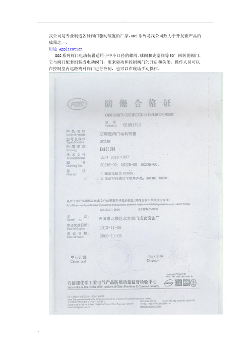
我公司是专业制造各种阀门驱动装置的厂家,802系列是我公司致力于开发新产品的成果之一。
用途 Application802系列阀门电动装置适用于中小口径的蝶阀、球阀和旋塞阀等90°回转的阀门,它与阀门配套组装成电动阀门,用来驱动和控制阀门的开启和关闭。
操作人员可以在控制室内远距离对阀门进行控制,也可以在现场手动操作。
结构 Construction802系列阀门电动装置主要由专用电机、减速机构、行程控制机构、转炬控制机构、开度指示机构和手轮等组成。
☆电机:阀门专用电机,额定运行时间10分钟,电机安装在箱体的外侧秒面,用齿轮与箱体内的减速机构连接。
☆减速机构:由直齿轮副、蜗杆蜗轮副和少齿差行星齿轮减速机构组成。
最后由输出轴输出动力,驱动阀门的阀杆,使阀门开启和关闭。
☆行程控制机构:采用凸轮机构,凸轮指针轴与输出轴同步,在开向和关向各有二个凸轮和微动开关,一个控制电机电源,一个接通指示灯。
☆转矩控制机构:采用蜗杆轴向窜动结构,蜗杆轴上装有蝶形弹簧,当电动装置有转矩输出时,蜗杆轴就会压缩蝶形弹簧产生轴向窜动(位移),蜗杆轴的轴向窜动量的大小与电机装置输出的转矩大小成正比,通过齿条和齿轮把蜗杆轴窜动量变成凸轮的偏转角度,然后用凸轮触动微动开关,切断电机电源。
☆开度指示机构:用于现场指示阀门开启程度,行程控制机构中凸轮指示轴的顶端装有刻度盘。
在凸轮指针轴的侧面装有供控制室开度表用的电位器,凸轮指针轴和电位器轴之间用一对升速直齿轮副连接。
☆手轮:箱体的侧面装有手轮,本产品没有手电切换手柄,为全自动型。
电气接线 Wiring diagram安装 Installation允许阀门电动装置任意位置安装,但必须注意电机尽量呈水平位置,在不可避免的情况下电机非倾斜不可时,电机的轴伸应向下倾斜,防止因意外润滑油进入电机内部。
阀门电动装置与阀门安装之前,须检查一下电动装置的接盘与轴孔尺寸是否与阀门一致。
安装步骤 Procedure of Installation1、把阀门的阀杆连同键一起放入电动装置的输出轴孔内,然后用螺杆栓把电动装置的接盘和阀门的法兰盘紧固。
3英寸x21英寸电动带子剃面器指南说明书
3" x 21" Electric Belt Sander8005684Owner’s ManualSpecifications• Sands wood or metal and removes paint and rust• 120V, 60 Hz• 7.5 Amp• 1,240 ft/min. (6.3 m/sec)• 3" x 21" belt• Dust collection bag• Double insulated <--- checking on this....• Trigger switch with lock-on button General Safety Rules1. Warning!Read and understand all instructions before using power tool. Save these instructions.2. Work Area.• Keep your work area clean and well lit. Do not operate power tools in explosive atmospheres, such as in the presence of flammable liquids or gases. Keep bystanders, children and visitors away while operating a power tool.3. Electrical safety.• Grounded tools must be plugged into an outlet properly installed and grounded in accordance with all codes and ordinances. Never remove the grounding prong or modify the plug in any way. Do not used any adapter plugs. Check with a qualified electrician if you are in doubt as to whether the outlet is properly grounded.• Double insulated tools are equipped with a polarized plug (one blade is wider than the other.) This plug will fit in a polarized outlet only one way. If the plug does not fit fully in the outlet, reverse the plug. If it still does not fit, contact a qualified electrician to install a polarized outlet. Do not change the plug in any way.• Avoid body contact with grounded surfaces such as pipes, radiators, ranges and refrigerators.• Do not expose power tools to rain or wet conditions.• Do not abuse the cord. Never use the cord to carry the tool or pull the plug from an outlet. Keep cord away from heat, oil, sharp edges or moving parts. Replace damaged cords immediately.4. Personal safety.• Stay alert, watch what you are doing and use common sense when operating a power tool. Do not use tool while tired or under the influence of drugs, alcohol, or medication.• Dress properly. Do not wear loose clothing or jewellery. Tie back long hair. Keep hair, clothing and gloves away from moving parts. • Avoid accidental starting. Be sure switch is off before plugging in.• Remove adjusting keys or switches before turning the tool on.• Do not over reach Keep proper footing and balance at all times.• Use appropriate safety equipment. Always wear eye, hearing and breathing protection.5. Tool use and care.• Use clamps or other practical ways to secure and support the workpiece on a stable platform• Do not force tool, use the correct tool for the required application.• Do not use tool if switch does not turn it on or off.• Disconnect the plug from the power source before making any adjustments, changing accessories, or storing the tool.• Store tools out of reach of children and other untrained persons.• Maintain tools with care.• Check for misalignment or binding of moving parts, breakage of parts, and any other condition that may affect the tool’s operation. If damaged, have the tool serviced before further use.• Only use accessories that are recommended by the manufacturer for your model.6. Service.•Tool service must be performed only by qualified repair personnel.• When servicing a tool, use only identical replacement parts. Follow instructions in the maintenance section of this manual.Belt Sander Safety Hazards1.Observe the applicable regulations when sanding painted surfaces Warning:• Some dust created by power sanding, sawing, grinding and other construction activities contains chemicals known to cause cancer, birth defects or other reproductive harm. Some examples of these chemicals are: lead from lead-based paints, crystalline silica from bricks and cement and other masonry products, arsenic and chromium from chemically treated lumber. Risk from these exposures varies depending on frequency and duration of exposure. To reduce exposure to these chemicals, work in a well ventilated area. Wear approved safety equipment, such as a respirator with filters rated for the debris produced by the job.• Children and pregnant women must not enter the work area.• Do not eat, drink or smoke in the work area.2.Whenever possible, use a vacuum extractor for dust collection.3.Remove dust and other waste materials in an environmentally safe manner. All persons entering the work area must wear a mask specially designed for protection against lead paint dust and fumes. AssemblyWarning:Always ensure that the power cord of the belt sander is unplugged from its electrical outlet prior to assembly,adding any accessories, or making adjustments to the tool.Changing a sanding belt:1.Pull out the tension lever of the front wheel frame and slide the sanding belt out.2.Slide a new sanding belt on, then push on the tension lever of the front wheel frame.3.Plug in the sander.4.Grip the sander firmly with both hands. Lift the tool and squeeze the power switch. As the sanding belt turns, watch it to see if it is turning on-centre and not moving to the left or right. If the sanding belt is moving to the left or right, turn the tension adjuster left or right until the sanding belt turns on center. Then turn off the belt sander.To Attach the dust bag:1.To attach the dust bag, simply clip the opening onto the dust port located on the left housing. Operating InstructionsThe power switch:1.To start the belt sander, depress the power switch. To stop the tool, release pressure on the power switch.2.To lock the power switch in the ON position for continuous operation, depress the power switch and push in on the switch lock. The tool will continue to run. To turn off the tool squeeze and release the power switch once.Warning:Prior to each use of the belt sander, ensure the switch lock mechanism is working properly. Always release the switchlock mechanism before disconnecting the belt sander fromits electrical outlet. Failure to do so will cause the tool tostart immediately the next time it is plugged into an outlet,resulting in possible injury or property damage.Sanding procedure:1.When sanding a work piece, always push and pull the sander over the workpiece with both hands firmly gripping the tool. Never pass hands or fingers directly in front of, to the rear, or below the sanding belt.2.Ensure the work piece is free from nails and any other foreign objects which could damage the sanding belt.3.Make sure the work piece is supported at all times. Whenever possible, secure the workpiece in a vise or with clamps (not included.) If necessary, use a roller stand with larger workpieces.4. Plug the power cord into the nearest receptacle5.Firmly grip the sander with both hands, then squeeze the power switch to turn on the tool. If desired, use the switch lock to run the belt sander in its continuous mode.6.Allow the sanding belt to turn up to full speed before feeding the sanding belt into the workpiece.7.To avoid damaging the workpiece, always sand parallel to the grain of the wood.8.Do not force the belt sander to remove material faster than it isdesigned to. Push and pull the sanding belt gradually along the surface of the work piece.9.Once the sanding job is completed turn off the belt sander and wait until the sanding belt stops turning. Then unplug the power cord from its electrical outlet. Inspection, maintenance and cleaning Warning: Ensure the power switch of the belt sander is in its off position and that the tool is unplugged from its electricaloutlet before performing any inspection, maintenance, orcleaning procedures.2.Before each use inspect the general condition of the belt sander. Check for loose screws, misalignment or binding of moving parts, damaged electrical wiring, dull or damaged sanding belt, and any other condition that may affect its safe operation. If abnormal noise or vibrations occurs, have the problem corrected before further use. Do NOT use damaged equipment.3.Carbon brushes. To maintain peak efficiency of the belt sander motor it is recommended that every two to six months the carbon brushes be examined. The carbon brush should be free of dust and dirt. The carbon brush should be replaced when it wears down to 3/16" in length. the carbon brush should slide freely in and out of the brush holder without sticking. To check the carbon brush, remove the brush holder cover located at the front of the belt sander. Lift out the carbon brush to inspect. If cleaning is necessary, rub the carbon brush thoroughly with a pencil eraser. Next, clean the brush holder opening with compressed air or a clean cloth. Then replace the carbon brush and the cover.4.To clean, the ventilation openings should be kept clean and free of sawdust and debris. The most effective way to clean the ventilation openings with is with compressed air. The outer body may be cleaned with a clean cloth and a mild detergent. Do not use solvents. Do not immerse in liquids.Parts List1Close cover2Bearing3Shaft gear4Bearing5Dust suction cover 6Fan7Screw8Plain washer9Cover10Large belt wheel 11Belt cover12Screw13Switch14Cable cover15Cable plug16Right housing17Cable pressure18Left housing19Bearing20Plain washer21Large gear22Column23Retainer24Nameplate25Carbon brush frame 26Nut27Carbon brush28Brush holder cover 29Plain washer30Adjustment spring 31Adjustment nut 32Orientation Pin33Screw34Oil bearing35Ring washer36Rear wheel37Ball bearing38Brake wheel axis39Nameplate40Screw41Spring42Screw43Bearing seat44Front cover45Screw46Sanding belt47Cushion48Bottom plate49Belt50Small belt wheel51Front wheel52Front wheel drive axis 53Front wheel frame54Screw55Screw56Stator57Retainer58Rotor59Grip。
Rotary Lift 电动扬平台产品说明书
P A R T S B R E A K D O W NP A R T S B R E A K D O W N SPOA7, SPOA9, SPO9(200 Series Lifts)SPOA7Capacity 7,000 lbs.SPOA9Capacity 9,000 lbs.SPO9Capacity 9,000 lbs.1.L.H. Column Weldment...........................................N7192.R.H. Column Weldment..........................................N7293.Column ExtensionSPOA7 & SPO9....................................................N45SPOA9..................................................................N410EH-1 MODEL SPOA7/SPOA9/SPO9...................N46EH-2 MODEL SPOA7/SPOA9/SPO9...................N47EH-4 MODEL SPO9.............................................N494.Carriage Yoke Weldment........................................N895.Arm Pin....................................................................FJ78386.3/16" x 2" Long Cotter Pin (41250)7.Hydraulic Cylinder...................................................N3428.Power UnitSPOA7 1Ø 60Hz..................................................*P1052/P752SPOA7 1Ø 50 Hz.................................................*P1055/FA791SPOA7 3Ø...........................................................*P1053/P753SPO9/SPOA9 1Ø 60Hz.......................................*P1002/P702SPO9/SPOA9 1Ø 50Hz.......................................*P1089/FA788SPO9/SPOA9 3Ø................................................*P1047/P7479.Power Unit Hose.....................................................FJ83710.5/16”-18NC x 1-1/2” Bolt (Full Thread) (40271)11.5/16” External Tooth Lockwasher (40854)12.5/16”-18NC Hex Nut (40670)13.Actuator Pin Handle................................................FJ7985-114.Actuator Pin.............................................................N121-115.Retaining Pin...........................................................N119-316.Arm Restraint Spring...............................................FJ7656-217.Bleeder Screw (Specify Manufacturer)...................N/A18.Carriage Bumper.....................................................FJ7391-219.120T Gear Block.....................................................FJ774920.Approach bumper....................................................FJ7391-121.1/2”-13NC Hex Lock Nut (40703)22.Truarc #5304-75 Klipring for 3/4” Shaft (41411)23.Sheave....................................................................FJ7116-124.1/4”-20NC Zinc Hex Nut (40627)25.Sheave Cover..........................................................N119-126.1/4”-20NC x 3/8” Lg. PHMS Plated (2 pcs.) (40063)27.Slider block..............................................................FJ736028.3/4” Concrete Anchor..............................................FJ738029.1-1/2” O.D. x .760-.770” I.D. x .045” Bushing (41388)30.1Ø 1/4”-20NC x 2” HHCS (40109)3Ø 1/4"-20NC x 2-3/4" HHCS (40114)31.1/4”-20NC Insert Locknut (40642)32.1/8” x 1” Lg. Cotter Pin (41200)33.Switch Bar Assembly1Ø.........................................................................N4153Ø for use with Control Panel..............................FJ7613-23Ø for use with Drum Switch................................N43434.Spotting Wheel Dish Kit..........................................FF72935.Restraint Gear.........................................................FJ775036.3/8”-16 NC x 3/4” Long Flanged HHCS (40124)*37.Arm Restraint Kit (1 arm)........................................**FJ7888 38.Overhead HoseSPOA7..................................................................FJ838SPOA7 EH-1 MODEL..........................................FJ840SPOA7 EH-2 MODEL..........................................FJ841SPOA9/SPO9.......................................................FJ839SPOA9/SPO9 EH-1 MODEL................................FJ842SPOA9/SPO9 EH-2 MODEL................................FJ843SPO9 EH-4 MODEL.............................................FJ84539.Equalizer CablesSPOA7..................................................................FJ7449SPOA7 EH-1 MODEL..........................................FJ7545SPOA7 EH-2 MODEL..........................................FJ7546SPOA9..................................................................N33SPOA9 EH-1 MODEL..........................................N34SPOA9 EH-2 MODEL..........................................N35SPO9....................................................................FJ7450SPO9 EH-1 MODEL.............................................FJ7547SPO9 EH-2 MODEL.............................................FJ7528SPO9 EH-4 MODEL.............................................FJ7601 40.Capacitor Box..........................................................FA7147-1Capacitor Box Cover Plate......................................FA7203-1Drum Switch............................................................FA7205Drum Switch Handle................................................FA7205-1M5 x 10 PHMS, Plated............................................4027541.Locking Latch Cable................................................FJ7594-1EH-1 & EH-2 for SPOA7/SPOA9/SPO9..................FJ7595-1 EH-4 for SPO9........................................................FJ760042.3/8”-16NC x 1” Flanged HHCS (40144)43.3/8”-16NC Flanged Locknut (40664)44.Sheave Shaft...........................................................FJ7444-845.1/4”-20NC x 3/4” HHCS Grade 5 (40099)tch Cable Guide...................................................N6947.Hose Clip (4 req’d-Overhead).................................FJ720648.#12 Type B x 1/2” Lg. Sl. HWHTS (40057)49.5/16”-18NC x 3/8” PHMS (40227)50.Branch Tee..............................................................FJ766851.Hose Clip (6 req’d-Column).....................................FJ749952.3/8”-16NC x 1/2” Flanged HHCS (40122)53.1/4”-20NC Flanged Locknut (40641)54.3/4” Spacer..............................................................FJ787155.Limit Switch Assembly(use with Control Panel Power Unit)For units using less than or equal to 250V...........N413For units using above 250 V.................................N414Limit Switch(use with Control Panel Power Unit)For units using less than or equal to 250V...........N413-1For units using above 250 V.................................FJ7979-1 Contactor & Box (use with Drum Switch Power Unit)All Voltages...........................................................N432Contactor (use with Drum Switch Power Unit)All Voltages...........................................................N432-156.1/4” External Tooth Lockwasher (40779)57.3/8” External Tooth Lockwasher (40845)58.Spring Pin-1/4" dia. x 1-1/2" Lg. (Stainless) (14427)59.1/4”-20NC x 1” HHCS Grade 5 (40108)60.3/8"-16NC x 1-1/2" HHCS Grade 5 (40200)61.3/8" Spring Washers (40818)62.Adapter Swivel Pin..................................................FJ79-663.3/8" Internal Tooth Washer (40843)64.3/8"-16NC x 5/8" Lg. HHCS Grade 8 (40155)65.3/32" Hog Ring for 1/2" Shaft (8 req’d)....................FJ671-666.Adapter Pin..............................................................FJ671-367.High Step Adapter...................................................FJ671-168.Low Step Adapter....................................................FJ671-269.Actuator Assembly..................................................N43370.Rear Outer Arm WeldmentSPOA7..................................................................N239-1SPOA9..................................................................N238-1SPO9....................................................................N241-1 71.Front Outer Arm WeldmentSPOA7..................................................................N240-1SPOA9..................................................................N237-1SPO9....................................................................N241-1 72.Rear Inner Arm WeldmentSPOA7..................................................................N239-2SPOA9..................................................................FJ7493-6 SPO9....................................................................N241-2 73.Front Inner Arm WeldmentSPOA7..................................................................FJ7256-2 SPOA9..................................................................FJ7491-6 SPO9....................................................................N241-2 74.Rear Inner Arm Weldment (R/A)SPOA7..................................................................N2101-1SPOA9..................................................................N2102-1SPO9....................................................................N2104-1 75.Front Inner Arm Weldment (R/A)SPOA7..................................................................N2100-1SPOA9..................................................................N2103-1SPO9....................................................................N2104-176.Column Mounting Bracket.......................................N43977.Adapter Assembly...................................................FJ6161Rubber Pad.............................................................FJ6161-178.L.H. Overhead Weldment (Outer)...........................N437-179.R.H. Overhead Weldment (Inner)...........................N438-180.Adapter Assembly...................................................FJ6159Rubber Adapter.......................................................FJ6158-4 81.Control Panel Kit(Panel and Attaching Hardware)3Ø 208V/60 Hz....................................................FA7146-1 3Ø 230V/60 Hz....................................................FA7146-2 3Ø 460-480V/60 Hz. or 380-415V/50Hz.............FA7146-3 3Ø 480V/50 Hz....................................................FA7146-4NOTE: Standard hardware items should be purchased from local hardware source when possible.RUBBER ADAPTERS*Two different Power Units were used. Please check to see which you have before calling for service. Thank You.**Includes items 13, 14, 15, 16, 19, 35, 58, 60, 61。
扬力公司的激光切割机使用说明书
扬力公司的激光切割机使用说明书扬力公司的激光切割机使用说明书1. 引言在工业制造领域,激光切割机已经成为不可或缺的工具。
激光切割技术以其高精度、高效率和可靠性而闻名于世。
扬力公司自豪地推出了一款先进的激光切割机,本使用说明书将帮助您熟悉和正确使用我们的产品。
2. 产品概述扬力激光切割机是一种高能激光器,可实现对金属、塑料、木材等材料的精确切割。
我们的切割机配备了一系列先进的功能和控制系统,以满足不同客户的需求。
3. 安全操作指南3.1 安全防护装置我们的切割机配备了一套完善的安全防护装置,包括防护罩、紧急停止按钮和感温传感器等。
在操作前,请确保这些设备正常运作,并在必要时进行维护和检修。
3.2 操作人员的个人保护在操作激光切割机时,请佩戴适当的个人保护装备,如安全眼镜、手套和耳塞等。
确保您的身体部位远离激光切割区域,并保持清晰的思维。
3.3 紧急事故处理如果发生意外情况或紧急情况,立即按下紧急停止按钮,并向相关人员寻求帮助。
不要擅自解决问题,以免造成进一步的伤害或损坏。
4. 操作说明4.1 开机和关机在使用激光切割机之前,请确保电源和气源连接正常。
按下电源按钮并等待系统启动。
当您完成工作时,按下关机按钮并断开电源和气源供应。
4.2 材料准备将待切割材料按照要求处理和整理,确保其平整、干燥且无杂质。
根据材料的种类和厚度进行相关设置,并将其放置在工作台上。
4.3 参数设置激光切割机配备了一套先进的控制面板,可通过它来设置切割参数,如功率、速度和切割深度等。
根据您的需求和材料特性,选择合适的参数进行设置。
4.4 切割操作在进行切割操作之前,请确保切割区域周围清洁,并将防护罩关闭。
按下启动按钮,激光切割机将按照您设置的参数进行切割操作。
在操作过程中,请密切注意切割状态和设备运行情况。
4.5 完成和清理当您完成切割任务时,切断电源和气源供应。
清理切割区域和设备表面的杂质,并确保设备处于良好的工作状态。
5. 常见故障排除5.1 切割偏移如果切割结果与预期不符,请检查切割参数和材料设置是否正确。
扬修电动头2SA8说明书
安 全该机电设备是在工业强电流的条件下使用的。
在操作中,该设备有些零部件带电,同时有些零部件能够运动或转动。
因此,未经许可拆下保护罩盖,不合理的使用,不正确的操作或不合适的维护,均会造成严重的人身伤害或设备损坏。
为了人身和设备的安全,必须保证:仅允许专业人员对设备进行作业。
在对该设备进行作业时,应按说明书的要求进行。
严禁非专业人员对该设备进行作业。
目 录1、使用须知 (1)2、工作原理与结构组成 ................................................. (1)2.12SA8系列电动执行机构工作原理 (1)2.2结构组成 (2)3、连接与安装 (2)3.1机械连接形式 (2)3.2机械安装注意事项 (3)3.3电气连接及安装 (3)3.4特殊场合的分体安装 (3)4、功能与操作 (4)4.1操作面板显示与说明 (4)4.2遥控器的使用说明 (4)4.3设置项目 (5)4.4一般功能与操作 (6)4.5高级功能与操作 (8)4.6其他功能与操作 (11)4.7紧急功能与操作 (11)5、参数浏览 (12)6、维修及保养 (13)6.1手动操作注意事项 (13)6.2维护周期 (13)6.3电池说明 (13)附录1:2SA8系列电动执行机构用户接线图 (14)附录2:2SA8系列电动执行机构主要技术参数 (16)附录3:2SA8系列电动执行机构出厂设置参数一览表 (17)附录4:2SA8系列电动执行机构可能的故障及解除办法 (18)★在安装调试2SA8系列电动执行机构前,请仔细阅读本说明书。
★本说明书如有更改,恕不另行通知!1、使用须知1) 2SA8系列电动执行机构在运输、保管、安装、调试、运行、维修时应严格按照本说明书的各项要求进行,以避免发生故障及损伤;2) 非专业工程技术人员请勿随意安装、调试、运行、维修电动执行机构;3) 吊装时,应使用缆绳套在电机及接线罩盖上起吊电动执行机构,如图1所示,不允许将缆绳系在手轮、切换手柄以及外露电缆上起吊或移动电动执行机构;4) 电动执行机构未安装使用时,应贮存在室内干燥处,安装在管道上时,管路振幅大于0.05mm(单图1 吊装示意图2、工作原理与结构组成2.1 2SA8系列电动执行机构工作原理154 3 2图2 工作原理示意图1、电动机2、蜗轮3、传感器4、输出轴5、蜗杆2SA8系列电动执行机构的电气控制组件接收外部控制信号,使电机输出动力,通过蜗杆蜗轮及离合器,最终传至输出轴,从而控制阀门阀位,达到运行的目的。
- 1、下载文档前请自行甄别文档内容的完整性,平台不提供额外的编辑、内容补充、找答案等附加服务。
- 2、"仅部分预览"的文档,不可在线预览部分如存在完整性等问题,可反馈申请退款(可完整预览的文档不适用该条件!)。
- 3、如文档侵犯您的权益,请联系客服反馈,我们会尽快为您处理(人工客服工作时间:9:00-18:30)。
安 全该机电设备是在工业强电流的条件下使用的。
在操作中,该设备有些零部件带电,同时有些零部件能够运动或转动。
因此,未经许可拆下保护罩盖,不合理的使用,不正确的操作或不合适的维护,均会造成严重的人身伤害或设备损坏。
为了人身和设备的安全,必须保证:仅允许专业人员对设备进行作业。
在对该设备进行作业时,应按说明书的要求进行。
严禁非专业人员对该设备进行作业。
目 录1、使用须知 (1)2、工作原理与结构组成 ................................................. (1)2.12SA8系列电动执行机构工作原理 (1)2.2结构组成 (2)3、连接与安装 (2)3.1机械连接形式 (2)3.2机械安装注意事项 (3)3.3电气连接及安装 (3)3.4特殊场合的分体安装 (3)4、功能与操作 (4)4.1操作面板显示与说明 (4)4.2遥控器的使用说明 (4)4.3设置项目 (5)4.4一般功能与操作 (6)4.5高级功能与操作 (8)4.6其他功能与操作 (11)4.7紧急功能与操作 (11)5、参数浏览 (12)6、维修及保养 (13)6.1手动操作注意事项 (13)6.2维护周期 (13)6.3电池说明 (13)附录1:2SA8系列电动执行机构用户接线图 (14)附录2:2SA8系列电动执行机构主要技术参数 (16)附录3:2SA8系列电动执行机构出厂设置参数一览表 (17)附录4:2SA8系列电动执行机构可能的故障及解除办法 (18)★在安装调试2SA8系列电动执行机构前,请仔细阅读本说明书。
★本说明书如有更改,恕不另行通知!1、使用须知1) 2SA8系列电动执行机构在运输、保管、安装、调试、运行、维修时应严格按照本说明书的各项要求进行,以避免发生故障及损伤;2) 非专业工程技术人员请勿随意安装、调试、运行、维修电动执行机构;3) 吊装时,应使用缆绳套在电机及接线罩盖上起吊电动执行机构,如图1所示,不允许将缆绳系在手轮、切换手柄以及外露电缆上起吊或移动电动执行机构;4) 电动执行机构未安装使用时,应贮存在室内干燥处,安装在管道上时,管路振幅大于0.05mm(单图1 吊装示意图2、工作原理与结构组成2.1 2SA8系列电动执行机构工作原理154 3 2图2 工作原理示意图1、电动机2、蜗轮3、传感器4、输出轴5、蜗杆2SA8系列电动执行机构的电气控制组件接收外部控制信号,使电机输出动力,通过蜗杆蜗轮及离合器,最终传至输出轴,从而控制阀门阀位,达到运行的目的。
122.2 结构组成2SA8系列电动执行机构采用非侵入式结构设计,操作方式为磁感应操作,通过按钮或红外手持式遥控器进行通讯,利用先进的变频输出、光电传感器精确地进行位置测量,技术先进,结构简单,可靠性好。
主要部件如图3所示,有:变频电机、使用带传感器输出的蜗轮蜗杆传动部分、自动复位的手电动切换部件、含CPU 主板控制模块和变频器的电气控制组件、各种形式的输出连接部分。
4321567891011121314图3 电动执行机构主要结构1、连接盘2、箱体3、蜗轮4、输出轴5、手切换部件6、传感器(转速测量)7、接线罩盖8、手轮9、离合器10、电气控制组件 11、传感器(行程控制)12、行程部件 13、蜗杆14、电机 3、连接与安装3.1 机械连接形式带螺纹套的空心轴,可承受推力及转矩——GB12222 《多回转阀门驱动装置的连接》 带键槽的空心轴,可承受转矩——GB12222 《多回转阀门驱动装置的连接》带键槽的阶梯空心轴,可承受转矩——GB12222 《多回转阀门驱动装置的连接》带爪连接空心轴,可承受转矩——JB2920 《阀门电动装置型式、基本参数和连接尺寸》电动执行机构的最佳安装形式是其输出轴轴线处于垂直位置,且连接法兰向下。
3.2 机械安装注意事项检查连接部分的正确性与准确性。
使用带螺纹套空心轴时,应在螺纹部分加油润滑。
将带有连接法兰的电动执行机构安装在最终控制元件上(如阀门),注意对中。
避免连接件受冲击和外力的作用。
应使用强度为8.8级以上的螺栓以及防松垫圈,旋入深度应大于螺栓直径的1.25倍。
检查电动执行机构及阀门是否正常,使用手动操作检查电动执行机构与阀门连接是否正确。
露天摆放时请将接插件插牢,请勿将穿线孔朝天摆放。
现场安装调试后,必须将接线插头插牢并将穿线接头和控制罩盖处螺钉旋紧,确保密封。
3.3 电气连接及安装检查电源电压是否满足铭牌的要求。
未经扬州电力设备修造厂许可,请勿移去任何防护罩盖(接线罩盖除外),否则将不负责保修由此造成的损坏。
用户必须提供合适的外部电气保护设备(如断路器、空气开关或保险丝),以保证人员和执行机构的安全。
在执行机构外部箱体上有一M8的接地螺栓,用来连接内外部接地。
在卸下接线罩盖前应确保无动力电源接入并用L型六角扳手松开四个螺栓并拆下接线罩盖。
电缆入口:●电缆的密封和入口应符合国际标准或具有认证资格的权威机构认可。
尤其是危险区,密封必须符合标准。
电缆密封套、收缩管、插头和适配器应使用经过鉴定的合格品。
●2SA8系列电动执行机构的电缆入口连接螺纹规格为pg21×2;●接线使用的电缆型号和尺寸应与电缆入口相适合,为保证防水和防爆,将电缆密封管旋紧(至少5圈)并用螺纹密封剂堵住。
尤其是在防爆环境中,务必使用螺纹密封剂。
●若电缆密封管已经去除,将电缆入口处拆除的零件放回到原来的位置以免丢失。
●未使用的电缆入口,应用带有螺纹的钢制或铜制的密封旋塞堵住,对于防爆结构还应使用螺纹密封剂。
在安装和使用过程中,应确保做好电动执行机构的密封防火措施(尤其是接线、调试的全过程应及时做好防护措施),防止水、尘等异物进入执行机构,影响执行机构的可靠运行。
3.4 特殊场合的分体安装2SA8系列电动执行机构可以通过采用分体安装组件来实现其控制单元和机械部分的分体安装。
分体安装最远距离可达10米,在以下三种情况下,可采用分体安装:安装现场环境温度过高或过低;安装现场振动很大,无法消除;安装现场不便于调试或现场安装空间不够;完整的分体安装组件包括连接用屏蔽电缆。
有3米、5米、和10米三种标准长度可供选择。
用户如有其他特殊要求,应在订货时说明。
34、功能与操作4.1 操作面板显示与说明图4 操作面板示意图指示灯逻辑状态说明三位状态选择开关说明2、全开位置――红灯亮、绿灯灭;3、关闭过程――绿灯闪、红灯亮;4、全关位置――绿灯亮、红灯灭;5、中间位置――红灯亮,绿灯亮;6、故障状态――黄灯亮;7、紧急状态――黄灯闪。
4.2 遥控器的使用说明1、性能参数电源 3节1.5V DC 7#电池使用距离≤3米(距执行机构显示窗口)2、按键功能45退出Esc取址键:获取当前需要控制的一个执行机构的通讯地址;状态切换键:就地控制、远方控制、参数浏览设置三种状态选择切换;取消键:退出当前状态;开向键:等同于ESC(OPEN)键的功能;停止键:等同于OK(STOP)键的功能;关向键:等同于NEXT(CLOSE)键的功能。
图5 遥控器面板示意图使用遥控器时,必须先按取址按键,取完地址之后才能对当前所取地址的执行机构进行操作。
按取址按键,遥控器红外传送窗口处的红灯闪烁,按停止键取址成功后,红灯停止闪烁,表示取址成功,即可进行其它相应操作。
每台执行机构的地址是唯一的。
若遥控器中取址按键不能及时获取到地址或操作距离减小,请更换电池,长期不使用时,请取出遥控器中电池4.3 设置项目包括:1、基本参数;2、I/O 参数;3、控制参数;4、阀位调试;5、中间位置;6、其他参数;说明:所有可以进行设置的菜单,按NEXT 按钮进行当前菜单的具体控制方式或者数字的设定,按下OK 按钮进入到下一级菜单,按下ESC退出到上一级菜单。
64.4 一般功能与操作(1)进入组态菜单(2)按下“OK”键,进入输入密码界面。
按“NEXT 键”选择所指数值,然后按“OK”键。
同上操作设置另2000。
(3)按下“OK”键(4)按下“NEXT”键3次下翻至“阀位调试”菜单(5)按“OK”键,访问“设置终端位置”菜单(6)按“OK”键,访问“关向设置终端位置”菜单。
按“NEXT”键,阀门动作,当阀门达到用户所需关向位置时,按“OK 键”停止。
(7)按“NEXT ”键,选择“开向终端位置”菜单。
(8)按“OK”键,访问“开向设置终端位置”菜单。
按“ESC”键,阀门动作,当阀门达到用户所需开向位置时,按“OK 键”停止。
说明面板按钮1) 阀位调试行程设置最小值为三圈!不同场合下用户定义旋向不一定完全相同,根据用户实际情况旋向,即确定开、关的 方向。
用户可根据实际情况,先设置开向终端设置,再设置关向终端设置,也可进行单项设置,原理同上。
7 2) 开向、关向限位方式: 操作进入“基本参数”菜单进行设置: :开向限位、关向限位可分别进行设置;限位方式有行程限位和力矩限位两种。
3) 开向、关向速度: 操作进入“基本参数”菜单进行设置: :单位(RPM ):每分钟转的圈数;执行机构的开向、关向速度必须设置在出厂给定的参数配 置范围之内;在不使用“多段速”控制方式的前提下有效;一旦使用“多 段速控制”,开向、关向的运行速度以多段速中设置的速度 为基准。
4) 就地、远方控制方式: 操作进入“控制参数”下“基本控制”菜单进行设置; : 若用户需要开关量控制:“就地”和“远方”的控制方式为以下两种:● 脉冲式:点按一下OPEN 或CLOSE 按钮,电动执行机构执行开或关的动作;● 维持式:一直按住OPEN 或CLOSE 按钮,电动执行机构才执行开或关的动作; 若用户需要模拟量控制:(4~20mA 电流控制)在“远方”控制方式中:选择“模拟量操作”;如果电流控制信号断线,执行机构报“信号断线”故障;若用户需要Profibus 总线控制: “远方”控制方式中:选择“总线控制”; 确定相应的总线地址。
5) 开关量输出信号1~8 操作进入“I/O 参数” 菜单进行设置; : 每一路开关信号出厂值请参照附录3;开关信号一共有15种状态选择,分别为:“在运行”、“就地”、“总故障”、“变频器故障”、“阀位故障”、“电池故障”、“开向行程限位”、“关向行程限位”、“开转矩动作”、“关转矩动作”、“信号断线”、“中间位置1”、“中间位置2”、“中间位置3”、“中间位置4”;如果开关量信号中有选择“中间位置1~中间位置4”的状态,具体含义见高级功能设置中“中间位置”的说明。
在一般工况下,如果用户无特殊需求,通过以上设置便可以使执行机构正常运行。
84.5 高级功能与操作2SA8系列电动执行机构具备一系列的高级功能,可以满足用户在不同工况下对执行机构的特殊运行需求,满足多种控制管理方式。