power quality measurement procedure
电能质量表使用方法

电能质量表使用方法英文回答:Electric power quality refers to the characteristics of electrical power that affect the performance of electrical equipment and systems. It is important to ensure that the electricity supplied to our homes and businesses is of good quality to avoid any negative impacts on the operation of electrical devices.To use an electric power quality meter, you first needto connect it to the electrical circuit you want to monitor. This can be done by attaching the meter to the power source or by using current transformers to measure the current flowing through the circuit. Once the meter is connected,it will start measuring various parameters of theelectrical power, such as voltage, current, frequency, and power factor.The meter will provide you with real-time data on theseparameters, allowing you to analyze the quality of the electrical power. For example, you can check if the voltage is within the acceptable range, if there are any voltage fluctuations or sags, or if the current is balanced in a three-phase system. You can also monitor the frequency stability and the power factor, which is a measure of how efficiently the electrical power is being used.By analyzing the data provided by the power quality meter, you can identify any issues or anomalies in the electrical system. For instance, if you notice that the voltage is consistently below the acceptable range, it could indicate a problem with the power supply or a faulty electrical device. Similarly, if the power factor is significantly lower than ideal, it could suggest that there are power losses in the system.Once you have identified any power quality issues, you can take appropriate measures to address them. This could involve contacting the utility company to investigate and resolve any power supply problems or replacing faulty electrical equipment. By ensuring good power quality, youcan prevent equipment damage, reduce energy waste, and improve the overall efficiency and reliability of your electrical system.中文回答:电能质量是指影响电气设备和系统性能的电能特性。
Fluke 43 Power Quality Analyzer 说明书
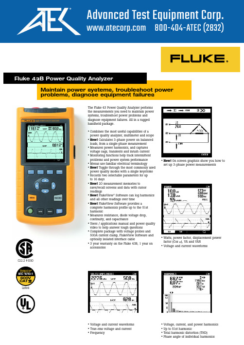
Maintain power systems, troubleshoot power problems, diagnose equipment failuresThe Fluke 43 Power Quality Analyzer performs the measurements you need to maintain power systems, troubleshoot power problems and diagnose equipment failures. All in a rugged handheld package.•Combines the most useful capabilities of a power quality analyzer, multimeter and scope •New!Calculates 3-phase power on balanced loads, from a single-phase measurement •Measures power harmonics, and captures voltage sags, transients and inrush current •Monitoring functions help track intermittent problems and power system performance •Menus use familiar electrical terminology•New!Toggle through the most commonly used power quality modes with a single keystroke •Records two selectable parameters for up to 16 days•New!20 measurement memories to save/recall screens and data with cursor readings•New!FlukeView ®Software can log harmonics and all other readings over time•New!FlukeView Software provides a complete harmonics profile up to the 51st harmonic•Measures resistance, diode voltage drop,continuity, and capacitance•Users / applications manual and power quality video to help answer tough questions•Complete package with voltage probes and 500A current clamp, FlukeView Software and optically isolated interface cable•3 year warranty on the Fluke 43B, 1 year on accessories•New!On screen graphics show you how toset up 3-phase power measurements•Watts, power factor, displacement power factor (Cos ), VA and VAR•Voltage and current waveforms•Voltage, current, and power harmonics •Up to 51st harmonic•Total harmonic distortion (THD)•Phase angle of individual harmonics•Voltage and current waveforms •True-rms voltage and current •FrequencyFluke 43B Power Quality Analyzer600V CAT IIIDesigned and Conforms toIEC 1010-1RC22.2 #1010ListedInput Characteristics RangesAccuracyInput impedance 1 M Ω, 20 pFVoltage rating600 Vrms, CAT IIIVolt / Amps / HertzTrue-rms voltage (AC+DC) 5.000 V, 50.00 V, 500.0 V, 1250 V*±(1 % + 10 counts)True-rms current (AC+DC)50.00 A, 500.0 A, 5.000 kA, 50.00 kA, 1250 kA ±(1 % + 10 counts)Frequency 10.0 Hz to 15.0 kHz ±(0.5 % +2 counts)CF Crest Factor 1.0 to 10.0±(5% + 1 count)PowerW, VA, VAR Reactive Power 250 W 2.50 kW, 25.0 kW, 250kW, 2.50 MW,±(2 % + 6 counts) Total Power 1-phase and 3-phase, 325 MW, 250 MW, 625 MW, 1.56 GW ±(4 % + 4 counts) Fundamental conductor balanced loads Power PF Power Factor0.00 to 1.00±0.04DPF Displacement Power Factor0.00 to 0.25not specified 0.25 to 0.90±0.040.90 to 1.00±0.03Hz Frequency fundamental 40.0 to 70.0 Hz ±(0.5 % + 2 counts)HarmonicsVolts, Amps, WattsFundamental V,A ±(3 % + 2 counts), W ±(5 % + 2 counts)2 to 31st Harmonic V,A ±(5 % + 3 counts), W ±(10 % + 10 counts)32 to 51st HarmonicV,A ±(15 % + 5 counts), W ±(30 % + 5 counts)Frequency of fundamental 40 Hz to 70 Hz±0.25 HzPhaseVolt & Amps (between Fund. & Harmonic)2nd (±3°) … 51st (±15°)Watts (between Volt Fund. & Amps Harmonic )Fund (±5°) … 51st (±15°)K-Factor (Amps & Watts) 1.0 to 30.0±10 %THD0.00 to 99.99±(3% + 8 counts)Sags & SwellsRecording times (selectable) 4 min to 16 daysVrms actual, Vrms max, 5.000 V, 50.00 V 500.0 V, 1250 V*Readings ±(2% +10 counts)min (AC + DC)Cursor readings ±(2% + 12 counts)Cursor Readings Average ±(2% +10 counts)Arms actual, Arms max,50.00 A, 500.0 A, 5.000 kA, 50,00 kAmin (AC + DC)RecordingRecording times (selectable) 4 min to 16 daysParametersChoose one or two parameters from one of the groups below V/A/Hz Line Voltage, Current, Frequency Power Watts, VA, VAR, PF, DPF, FrequencyHarmonics THD, Volts (Fund. & Harmonic), Amps(F&H) Watts(F&H) Freq.(H), %(H) of total, Phase(H), KF OhmsOhms, Diode, Continuity, Capacitance Temperature °C or °FScope DC Voltage, DC Current, AC Voltage, AC Current, Frequency, Pulse Width + or -,Phase, Duty cycle + or -, Peak max, Peak min, Peak min-max, Crest Factor TransientsMinimum pulse width 40 nsUseful bandwidth input 1DC to 1 MHz (with test leads TL24)Number of transients40Voltage threshold settings 20%, 50%, 100%, 200% above or below reference signalReference signalAfter START, the Vrms and frequency of the signal are measured. From these data a pure sinewave is calculated as reference for threshold setting.Vpeak min, Vpeak max at cursor 10 V, 25 V, 50 V, 125 V, 250 V, 500 V, 1250 V ±5% of full scale*Rated 600V CAT IIIAccuracies are stated as ±(percentage of reading + counts) without probes unless otherwise noted.Specifications are valid for signals with a fundamental between 40 and 70 Hz.• Continuously measure volts and amps on a cycle-by-cycle basis for up to 24 hours • Use cursors to read time and date of sags and swells• Catch voltage transients and waveform distortion• Catch and save up to 40 transients• Correlate the cause of transients with time and date stamps®Inrush Current Ranges Accuracy Current ranges (selectable) 1 A, 5 A, 10 A, 50 A, 100 A, 500 A, 1000 A Inrush times (selectable)l s, 5 s, 10 s, 50 s, 100 s, 5 min Cursor readings A peak max at cursor 1 and cursor 2±5% of full scale Time between cursors** 4 to 235 pixels ±(0.2% + 2 pixels)Scope, dual channel scope with measurement reading Input impedance Input 1 1 M Ω//12 pF; with BB120: 20 pF ±2 pF; with BB120 ±3 pF Input 2 1 M Ω//10 pF; with BB120: 18 pF ±2 pF; with BB120 ±3 pF VerticalVoltage ranges 50 mV/div to 500V/div ±(1% + 2 pixels)Vertical sensitivity, resolution 5 mV/div to 500V/div, 8 bit (256 levels)Bandwidth input 1 (voltage)DC to 20 MHz at inputs, or with BB120 and VPS100-R probe (Opt);1 MHz with TL24 LeadsBandwidth input 2 (current)DC to 15 kHz at inputs10 kHz with 80i-500s Current ClampCoupling DC, AC (10 Hz -3 dB)HorizontalTimeBase modes Normal, roll, single TimeBase ranges 60 s/div to 20 ns/div ±(0.4% + 1 pixel)Sampling rate 25 MS/s Record length 512 per channel (min / max samples)Trigger source Input 1 or Input 2 or Automatic selection Trigger mode Automatic Connect-and-View ™, Free Run,Single Shot.Connect-and-View ™Advanced automatic triggering that recognizes signal patterns and automaticallyadjusts triggering, timebase and amplitude. Automatically displays stable pictures of complex and dynamic signals like motor drive and control signals.Pre-trigger Up to 10 divisions Measurement readings,Volts & Amps (DC, AC, AC + DCrms, Peak max, Peak min, Peak min / max ),per channel selectable Frequency, Duty cycle + or - , Phase, Pulse Width + or -, Crest factor Ohms, Diode, Continuity, Capacitance Ohms 500.0 Ω 5.000 k Ω, 50.00 k Ω, 500.0 k Ω,±(0.6% +5 counts)5.000 M Ω, 30.00 M ΩDiode voltage 0 to 3.000 V ±(2% +5 counts)Continuity, shorts > 1 ms Beeper on at < 30Ω±5Ω,Capacitance 50.00 nF, 500.0 nF, 5.000 µF, 50.00 µF,±(2% +10 counts)500.0 µFTemperature***-100.0 °C to 400.0 °C,±(0.5% +5 counts)-200.0 °F to 800.0 °FMax current, max open circuit volt.0.5 mA, < 4 V (all functions above)MemoryNumber of screens 20Optical Isolated RS-232 Interface To printer Supports HP LaserJet ™, DeskJet, Epson FX/LQ and Postscript printers withoptional PAC91 Printer Adapter CableTo PC FlukeView Power Quality Analyzer software with PM9080 InterfaceAdapter includedFlukeView Power Quality Software Hardware requirements PC or 100% compatible with Windows 95, 98, Me, 2000, NT4.0.** 1 pixel = inrush time/250*** Requires optional temperature accessory• Inrush current up to 500A with supplied current probe• Use cursors to measure inrush current timing• Connect-and-View ™ scope for quick waveform display• Voltage and current channels• 20MHz bandwidth with optional 10:1 voltage probe.15kHz on current channel with optional current clamp• FlukeView ®Power Quality Analyzer software (included)• Capture measurement screens for professional-looking reports• Log readings to your computer disk drive • Works with Windows word processing,spreadsheet and analysis software• Windows 95 / 98 / Me / 2000 / NT 4.0PowerLine voltage adapter/battery charger includedInstalled battery Rechargeable NiCd pack (4 to 6 Vdc)Operating time 4 hoursCharging time 4 hours (Fluke 43B OFF) 12 hours (Fluke 43B ON)Refresh Cycle8 to 14 hours (to keep NiCd battery capacity optimal) EnvironmentalTemperature0ºC to 50ºC (32ºF to 122ºF)Environmental MIL 28800E, Type 3, Class III, Style BEnclosure IP51 (dust, drip water proof)Mechanical DataSize (H x W x D)232 x 115 x 50 mm (9.1 x 4.5 x 2 inches)Weight 1.1 kg (2.5 lbs.) incl. battery packSafetyFor measurements on 600 Vrms Category III installations, Pollution Degree 2 in accordance withEN61010-1 (1993) (IEC1010-1)ANSI/ISA S82.01-1994CAN/CSA-C22.2 No. 1010.1-92UL3111-1Surge protection 6 kV on input 1 and 2Floating measurements600 Vrms from any terminal to groundWarranty 3 years parts and labor on Fluke 43B, 1 year on accessories。
Power Quality Audit电能质量审计服务标准流

Power Quality Audit电能质量审计服务标准流上海捷实机电科技有限公司(EPSolutions)拥有在电能质量领域知识丰富的专家,具有多年研究和实践经验的资深顾问。
在全面掌握国外先进的电能质量解决方案的基础上,结合国内电能质量现状,为企业实施先评估后治理的步骤、采取面向敏感电气元器件、控制装置和整体设备等灵活的逐级嵌入式综合治理的理念,对设备进行深入细致的评估调查,充分了解生产工艺的具体要求、针对敏感设备的电气性能,将电压暂降治理的范围缩到最小,提供切实可行、最经济有效、成本最低的治理方案并专业实施电压暂降综合治理。
电能质量PQA技术服务步骤如下:1. 确认电能质量问题(1)电能质量评估调查(2)现场敏感设备巡查电能质量专家深入到企业的生产现场,巡查生产设备,了解生产过程对设备的具体工艺要求,对现场设备维护人员进行调查和访问,了解电能质量或电压暂降对敏感设备的具体影响,敏感设备对电压暂降的反应,根据在最恰当的层面嵌入最恰当的治理设备的理念确定设备的重要程度和敏感程度,缩小待治理设备的范围。
(3)设备及电气元器件的电能质量性能评估电能质量专家根据企业因电能质量引起的停机、停产事故的统计资料进行分析,结合多年研究和实践经验,参照敏感设备数据库、SEMI F47标准、IEC 61000-4-34电压暂降免疫标准核实设备、元器件的电压暂降敏感程度,确定问题的症结所在并确定治理项目范围。
2. 电压暂降治理(1)提供最经济有效的解决方案咨询在对企业电能质量(电压暂降)问题进行全面评估调查与测试研究后,考虑设备的敏感程度及工艺要求,根据面向敏感电气元器件、控制级和整台设备采取逐级由嵌入式到整体综合治理的方法,提供最佳解决方案。
增强治理方案的针对性,最大限度降低企业的解决电能质量(电压暂降)问题的成本。
(2)治理项目实施(a)对敏感设备和电气元器件进行电能质量保护在现场的评估和试验研究基础上,采用电压暂降补偿装置DySC 产品对敏感设备的某一部位、整体设备或整个生产流水线的进行相对集中的电能质量治理保护。
POWER QUALITY VCFP96M多功能表计说明书

Min/Max Reactive Power, Max Apparent Power), %THD up to 31st Level
Nominal 5A AC (Min-11mA, Max-6A)
45 to 65Hz
Automatic / Manual (Programmable)
8VA Max
Programmable (For energy)
For energy : 0.01k, 0.1k, 1k, 0.01m, 0.1m, 1m (depending upon CT ratio x PT ratio) For Power, Voltage, Current : Auto resolution For Power factor : 0.001
Accuracy
Memory Retention Measuring Parameters
3Ø-3 wire, 3Ø-4 wire, 2Ø-3 wire, 1Ø-2 wire
11 to 300V AC, (Phase to Neutral) 19 to 519V AC (Phase to Phase)
Humidity (non-condensing) Up to 85% RH
MECHANICAL SPECIFICATIONS
Mounting
Panel gms
DIMENSIONS
99
90.5 91.5
TERMINAL CONNECTIONS
NL
(en50160)Power Quality White Paper from Schneider
Quality of Supply Standards: Is EN 50160 the answer? AbstractFrom a regulatory perspective, the European Union has been a leader in developing and implementing quality of supply standards through its implementationof European Norm 50160. Some countries have used EN 50160 as the basis for their national quality of supply regulations. But the standard’s statistical models allow eight hours per week of unregulated power quality, and utilities compliance (or non-compliance) is assessed regardless of the severity of any events.This paper will outline the state of EN 50160 today: its benefits and possible areas of improvement, including those suggested by the European utility regulators themselves. The standard will be compared to national quality of supply standards from countries around the world to identify best practices and contrast the differences. In conclusion,a framework for quality of supply regulation will be proposed that will ensure that compliant utilities are providing a level of service that meets their customers’ expectations.I. Review of EN 50160History:The history of EN 50160 dates back to 1989 and the European Union directive 89/336 for Electromagnetic Compatibility. Intended to ensure the reliability of distribution networks (and proper operation of equipment connected to them), the so-called EMC Directive led to a 1989 definition of the physical characteristics of the low and medium voltage distribution systems by the organization UNIPEDE, and finally in 1994 a standard on “Voltage characteristics of electricity supplied by public distribution systems”. This standard was developed bya working group under CENELEC (European Committee for Electrotechnical Standardization) and was given the designation European Norm 50160, or EN 50160 [1]. Scope:The original mandate for EN 50160 was limited to low and medium voltage distribution systems and specifically the following characteristics of the supply voltage: frequency, magnitude, waveform and symmetry of the three-phase voltages. Low voltage is defined with an upper limit of1 kV RMS and medium voltage with an RMS value between 1kV and 35 kV. In the original scope, higher voltages were not considered.Supporting the requirement to define voltage characteristics in terms of frequency, magnitude, waveform and symmetry, EN 50160 provided definitions and in some cases measurement methods and compliance levels for 10 characteristics of the supply voltage:• Power frequency•Supply voltage variations•Rapid voltage changes (and Flicker)•Supply voltage dips• Short interruptions• Long interruptions• Temporary overvoltages•Supply voltage unbalance• Harmonic voltage• Mains signaling voltageSupply voltage characteristic Statistical Evaluation Compliance limit Power frequency95% of the time in 1 week 100% of the time in 1 week 50 Hz ± 1%50 Hz + 4% to -6% Supply voltage variations95% of the time in 1 week Uc ± 10% Rapid voltage changes (and Flicker) 95% of the time in 1 week Plt ≤ 1Supply voltage dips 1 year None given 1 Short interruptions 1 year None given 2 Long interruptions1 year None given 3 Temporary overvoltages 1 yearNone given Supply voltage unbalance 95% of the time in 1 week <2%Harmonic voltage 95% of the time in 1 week 95% of the time in 1 week See Figure 1 THD <8% Mains signaling voltage99% of the time in 1 day9% @ 100 Hz 1% @ 100 kHzTable 1: EN 50160 Compliance Limits1. Indicative value of 1000 dips/year provided2. Indicative value of “several hundreds” of short interruptions/year provided3. Indicative value of 50 long interruptions/year providedFigure 1: Harmonic limits in EN 50160Issues with EN 50160The primary issues preventing EN 50160 from being a comprehensive power quality standard can be broken down into five main points:1. As a consensus-driven standard, with equal representation from all countries, it reflects the lowest common agreed-upon value for PQ limits.2. Many of the most costly and most common PQ phenomena (dips, swells and interruptions) do not have compliance limits but only indicative values. In his paper “End use perceptions of Power Quality – A European Perspective” [2] Roman Targosz estimated the cost of dips and short interruptions within the EU at 86.5 Billion euro out of a 150 Billion euro estimated total cost of power quality.3. The scope is limited to medium voltage (35kV) networks and below.4. Measurement methods for each characteristic are not defined. By allowing utilities to evaluate compliance with undefined measurement methods, it will be impossible to compare results or apply fair noncompliance penalties.5. Many characteristics are evaluated for less than 100% of the measurement interval. This allows:• No limit on supply voltagevariations, flicker, voltage unbalance, individual harmonics or THD for 8.4 hours/week• No limit on mains signaling for 1.7hours/week8.0%2.0%5.0%1.0%6.0%0.5% 5.0%0.5%1.5%0.5%3.5%0.5%3.0%0.5%0.5%0.5% 2.0%0.5%1.5%0.5%0.5%0.5%1.5%0.5%THD357911131517192123H a r m o n i c O r d e rII. Alternative National Quality of Supply StandardsTo provide the most accurate comparison, medium voltage compliance limits for all national standards are used when compared to EN 50160.A. NorwayHistory:Regulation of quality of supply began in 1991 with the passing of the Energy Act. In 1995 mandatory reporting of interruptions greater than three minutes was added and 179 network companies were required to report key figures on voltage quality. On January 1, 2005 the Norwegian Water Resources and Energy Directorate (NVE) put into force “Regulations relating to the quality of supply in the Norwegian power system” [3]. Scope:The NVE regulations apply to all network voltage levels. The regulations provide definitions and in some cases measurement methods and compliance levels for the following supply voltage characteristics: • Frequency•Short interruptions•Long interruptions• Flicker Pst• Flicker Plt• Interharmonic voltage•Temporary overvoltages•Voltage dips• Voltage variations• Harmonic voltages• Mains signaling voltage•Rapid voltage change• Voltage unbalanceSupply voltage characteristic Statistical Evaluation Compliancelimitvs.EN50160 Power frequency 100% of the time 50 Hz ± 2% Different Supply voltage variations 100% of the time Uc ± 10% SameRapid voltage changes 1 change/dayUp to 24 changes/day>24 changes/day 6%4%3%HarderFlicker 95% of the time in 1 week100% of the time in 1 week Pst <= 1Plt <= 0.8HarderSupply voltage dips None given None given Same Short interruptions 1 year None given Same Long interruptions 1 year None given Same Temporary overvoltages 1 year None given Same Supply voltage unbalance 100% of the time <2% HarderHarmonic voltage Mean value for 10 minutesMean value for 10 minutes See Fig. 2THD <3%HarderHarderMains signaling voltage None given None given Easier Table 2: NVE Directorate Compliance Limits0.0% 1.0% 2.0% 3.0% 4.0% 5.0% 6.0%7.0%8.0%THD357911131517192123Figure 2: Comparison of EN 50160 and NVE Harmonic Voltage LimitsHow NVE regulations address identified limitations in EN50160:1. By focusing on just one country, Norwayhas been able to raise the compliance limitson rapid voltage changes, flicker, voltage unbalance and harmonic voltage. Higher order (above the 25th ) harmonic limits havebeen established, and the RMS variationaveraging period for supply voltagemagnitude is reduced from 10 minutes to 1minute. 2. Like EN 50160, dips, swells and interruptions still do not have compliance limits. NVE does require mandatory reporting of long interruptions (greater than 3 minutes) and further classifies interruptions as notified (where the customer was informed in advance of an impending interruption) and non-notified. This is a necessary first step to establishing compliance limits but does not set targets. 3. The scope is expanded up to and including 245 kV. 4. Measurement methods for each characteristic are not clearly defined. This clause “Measurements of the quality of supply shall be carried out in accordance with the relevant standards prepared by the International Electrotechnical Commission – IEC or the European Committee forElectrotechnical Standardization – CENELEC.” should be expanded to list the specific standards required for each characteristic. 5. Steady-state characteristics have compliance limits for 100% of the measurement period, with the exception of mains signaling voltage. Limitations of NVE regulations with respect to EN 50160: 1. Mains signaling voltage compliance limits not defined. 2. While frequency limits are defined for 100% of the measurement period, thecompliance limit has been reduced from 1% to 2%.B. ChinaHistory:In 1998 the State Grid Corporation of China produced “Management requirements forthe technical supervision of grid power quality” and in 2004 “Management requirements for the voltage quality of the power system and reactive power for the State Grid Corporation of China”. Most ofthe compliance standards have been developed between 2000 and 2004.Scope:Compliance limits apply at all voltage levels. The national standards are based on IEC standards including measurement methodologies, compliance limits and PQ monitoring product requirements. Standards specific to compliance limits are GB/T 12325-2003 “Admissible deviation of supply voltage”, GB 12326-2000 “Voltage fluctuation and Flicker”, GB/T 14549-1993 “Harmonics”, GB/T 15543-1995 “Admissible voltage unbalance factor”, GB/T 15945-1995 “Admissible deviation of frequency for power system”, and GB/T 18481-2001 “Temporaryand transient overvoltages” How Chinese standards address identified limitations in EN50160:1. The GB/T standards have higher compliance limits on frequency, rapid voltage changes, flicker, temporary overvoltages and low-order harmonic voltages.2. Dips, swells and interruptions still do not have compliance limits.3. The scope is expanded up to and including 500 kV.4. Measurement methods for each characteristic are clearly defined for voltage harmonics (IEC 61000-4-7) and flicker (IEC 61000-4-15). Other characteristics need clearly defined measurement methods.5. Steady-state parameters have compliance limits for 100% of the measurement period, with the exception of mains signaling voltage.Supply voltage characteristic Statistical Evaluation Compliancelimitvs.EN50160 Power frequency 100% of the time 50 Hz ± 1% Harder Supply voltage variations 100% of the time Uc ± 10% SameRapid voltage changes <= 1000/hourOther 4%2%HarderHarderFlicker 95% of the time100% of the time Pst <= 1Plt <= 0.8HarderHarderSupply voltage dips None given None given Same Short interruptions 1 year None given Same Long interruptions 1 year None given Same Temporary overvoltages 1 year √3 per unit Harder Supply voltage unbalance 95% of the time <4% EasierHarmonic voltage Mean value for 10 minutesMean value for 10 minutes Odd <2.4%Even <1.2%THD <3%HarderHarderHarderMains signaling voltage None given None given Easier Table 3: GB/T Compliance LimitsLimitations of Chinese standards with respect to EN 50160:1. Mains signaling voltage compliance limits not defined.2. Higher voltage unbalance compliance limits (4%).3. Higher-order harmonics have higher compliance limits than EN 50160. However,due to the natural high-frequency attenuation of the power system and the more stringent limits on low-order harmonics (which typically dominate networks due to power converters), the overall harmonic voltage compliance limits should be considered more stringent than EN 50160.0.0%1.0%2.0%3.0%4.0%5.0%6.0%7.0%8.0%THD471013161922Figure 3: Comparison of EN 50160 and GB/T Harmonic Voltage LimitsC. South AfricaHistory:The establishment of an Electricity Regulator in South Africa in 1995 led to the creation of five national Quality of Supply standards (NRS-048) between 1996 and 1998. In 2004 the National Energy Regulator Act was passed and in 2005 the National Energy Regulator of South Africa (NERSA) was established. NERSA enforces Quality of Supply standards within South Africa.Scope:Quality of Supply regulation applies to all voltage levels, and provides NERSA with a means of evaluating distribution companies. NRS-048-2 “Electricity Supply – Quality of Supply Part 2: Voltage characteristics, compatibility levels, limits and assessment methods” [4], defines measurement methods, compliance levels and limit levels. Table 6 shows the characteristic values for the number of voltage dips at medium voltage not exceeded by 95% and 50% of all sitesDepth 20-150ms150-600ms0.6-3s10-15%15-20%Y20-30%Z130-40% X140-60% X2S60-100% TZ2Table 5: Classification of voltage dipsX1 X2 T S Z1 Z2 95%20 30 110 30 20 45 50%7 7 7 6 3 4 Table 6: Number of voltage dips by classification, not exceeded at 50% and 95% of all sitesSupply voltage characteristic Statistical Evaluation Compliancelimitvs.EN50160Power frequency 99.5% of 1 year100% of 1 year 50 Hz ± 2%50 Hz ± 2.5%HarderSupply voltage variations 95% of the time in 1 week100% of the time in 1 week Uc ± 5%Uc +10%HarderRapid voltage changes None given None given Same Flicker 95% of the time in 1 week Plt <= 1 Same Supply voltage dips Less than 0.85 p.u. None given Same Short interruptions 1 year None given Same Long interruptions 1 year None given Same Temporary overvoltages None given None given Same Supply voltage unbalance 95% of the time <2% SameHarmonic voltage 95% of the time in 1 week95% of the time in 1 week See Fig. 4THD <8%HarderSameMains signaling voltage 99% of the time in 1 day Same asharmonicsEasier Table 4: NRS-048 Compliance Limits0.0%1.0%2.0%3.0%4.0%5.0%6.0%7.0%8.0%THD471013161922Figure 4: Comparison of EN 50160 and NRS Harmonic Voltage LimitsHow South African standards addressidentified limitations in EN50160:1. NRS-048 imposes stricter compliancelimits on voltage variations, frequency, andindividual harmonic levels. In the standard,100% compliance to tighter voltageunbalance limits is noted as beingconsidered.2. Like EN 50160, dips, swells andinterruptions still do not have compliancelimits. NRS-048 classifies dips according tomagnitude and duration (see table 5) andsets characteristic values. Interruptions areclassified as notified (where the customerwas informed in advance of an impendinginterruption) and non-notified. Voluntary andinvoluntary customer load reductions arealso identified. This is a necessary first stepto establishing compliance limits but doesnot set targets.3. The scope is expanded to extra-high voltage.4. Measurement methods for some characteristics are clearly identified. Flicker is to be measured according to IEC 61000-4-15 and Frequency to IEC 61000-4-30 Class A. For other characteristics, the measurement method is not clearly defined.5. Voltage variations and frequency characteristics have compliance limits for 100% of the measurement period. NRS-048 introduces limit levels in addition to compliance levels.D. ColombiaWhile not directly comparable to EN50160 due to lack of compliance limits, the national utility regulator in Colombia (Comisión de Regulación de Energía y Gas, or CREG) is clearly working towards power quality compliance limits. The recently enacted resolutions CREG 024 – 2005 and CREG 016 – 2007 require continuous monitoring of several power quality characteristics. Once statistics have been collected the regulator will move to implement compliance targets. The CREG resolutions require reporting of 10-minute values for voltage interruptions (number and duration), voltage deviations greater than 10% from nominal and greater than 60 seconds in duration flicker Pst, voltage unbalance, and voltage dips or swells lasting longer than one-half cycle. Based on the data being collected, it is unlikely that the CREG regulations will address many of the key shortcomings in EN 50160. The focus on dips, swells and interruptions is appropriate based on the economic impact of these characteristics, but flicker is used as a generic indicator of voltage waveform quality. Individual harmonic and THD compliance limits should be set as well.III. Improvement suggested by European Regulators for EN 50160The European Regulators Group for Electricity and Gas released a series of recommendations to improve EN 50160 in their July 2007 report “Towards Voltage Quality Regulation in Europe – An ERGEG Conclusions Paper” [5]. In this paper, ERGEG supports the following:“− some definitions, especially for voltage events like dips/swells and interruptions, should be improved in order to get comparable measurements all around Europe;− indicative values for voltage events should be avoided in the text of the EN 50160 norm, they can form the content of informative annexes or technical reports instead; − binding limits for voltage variations should be also targeted to customer protection and therefore the 95%-of-time clause should be reconsidered;− the scope of a VQ standard should be larger than the actual EN 50160 scope; the HV-EHV networks should be included and also the concept of “normal operating conditions” should be clarified;− product standards should also be reconsidered where appropriate in order to give correct signals to customers when they make their choices on the electrical products.In the current draft of EN 50160, the following improvements have been made:− Definitions for voltage variations measurement methods are specified. IEC 61000-4-30 methods have been applied.− The 95%-of-time clause has been removed for voltage variations, which now have a 99% compliance target and 100% limit.− The scope of the standard has been extended to high voltage.The draft standard still does not specifically identify measurement methods and retains a 95%-of-time clause on many voltage quality characteristics.IV. Recommendations for a National Quality of Supply StandardBy reviewing the development of Quality of Supply standards worldwide, best practices can be identified and used as a framework for new standards development.In China and South Africa, measurement methods are more clearly defined than in other national standards. Clearly this is critical when applying compliance limits (and associated penalties) and when attempting to compare one utility to another or one country to an international benchmark. The ability to draw economic investment to a country or region will require standardized measurement methodology. Quality of Supply compliance measurements should be based on international power quality measurement methods as defined by an IEC 61000-4-30 Class A device.As is the case in most national standards, all voltage levels in the network should have appropriate compliance and limit levels. Compliance limits set at 95% of a measurement interval should be strictly set, and limit levels for 100% of the interval must be defined. South Africa’s NRS-048 addresses this and allows utilities and customers to source appropriate equipment for the quality of power they will be exposed to.For non-steady state characteristics (dips, swells and interruptions), compliance limits should be defined. But these limits should be based on the impact to the customer, and so dips and interruptions should be classified on magnitude, duration, and customer notification.Harmonic voltage limits should be set based on the likelihood of occurrence and the damage they can cause. Norway and China addressed this issue by imposing harsher limits on the more common low-order harmonics. V. ConclusionsIt is clear when reviewing the Quality of Supply standardization efforts that utilities and regulators have focused on the most pressing local problems. But with increased globalization of industry, including the free transport of electrical distribution and production equipment, it will be increasingly necessary for power quality to be consistently monitored and regulated. Applying the recommendations in this paper, derived from the best practices of national regulators, would provide a common framework for quality of supply regulation and a necessary first step towards globally acceptable limits.VI. BiographyBrian Kingham received his Bachelor of Electrical Engineering from the University of Victoria in 1995. In 1995 he joined Power Measurement (now Schneider Electric) and is currently the Utility Market Manager for the company’s Power Monitoring and Control division.VII. References[1] European standard EN 50160 Voltage characteristics of electricity supplied by public distribution systems, CENELEC TC 8X, 2006[2] End use perceptions of Power Quality –A European Perspective, Roman Targosz, EPRI PQA 2007[3] The Norwegian directive on quality of supply, The Norwegian Water Resources and Energy Directorate, Karstein Brekke, Frode Trengereid and Espen Lier, ISSN: 1501-2840.[4] NRS-048-2, Electricity Supply – Quality of Supply Part 2: Voltage characteristics, compatibility levels, limits and assessment methods[5] Towards Voltage Quality Regulation in Europe – An ERGEG Conclusions Paper Ref: E07-EQS-15-04。
量具量仪中英文对照汇总

88.薄膜式气动量仪Membrane type pneumatic measuring instrument
89.光栅线位移测量系统Grating linear displacement measuring system
14. 被测量measurand
15. 影响量influence quantity
16. 变换值transformed value(of a measurand)
17. 测量信号measurement signal
18. 直接测量法direct method of measurement
22.原始轮廓 primary profile
23.残余轮廓residual profile
24.触针式仪器stylus instrument
25.感应位移数字存储触针式量仪displacement sensitive,digitally storing stylus instrument
26.触针式仪器的部件stylus instrument components
量具量仪中英文对照汇总
1.刀口型直尺:knife straigjht edge
2.刀口尺: knife straigjht edge
3.三棱尺three edges straigjht edge
4.四棱尺four edges straigjht edge
5.条式和框式水平仪
bar form and square levels
78.梯形螺纹量规型式与尺寸 Types and dimensions of metric trapezoidal screw threads
造纸专业常用语英汉词典
actuation time 动作时间 air seal 气封 ~ sepaing roll 热风辊 allowable limit 允许极限 allowance 允许公差,允许量
air borne drying气垫干燥,气托干燥 air intake 进风口,空气入口 ~ brake 空气制动器,风闸 ~ jet/nozzle 空气喷嘴
第 1 页,共 90 页
A absorbent felt 吸水毛毯 absorber 吸收器,吸收剂, 减震器 absorbing capacity 吸收能力 ~ tower 吸收塔 ~ pad 防震垫 ~ power 吸收能力 ~ quality 吸收性能,吸收能力 absorption 吸收作用 ~ ability 吸收能力 ~ band 吸收光带 ~ coefficient 吸收系数 ~ measurement 吸收测定 ~ rate 吸收率 ~ spectrum 吸收光谱 absorptive capacity 吸收能力 absorptivity 吸收能力,吸收率 accelerant 催速剂,促进剂 accelerated ageing 加速老化 ~ cement 速凝水泥 ~ oxidation 加速氧化 ~ weathering 人工加速风干 accelerating agent催速剂,促进剂 accelerator 加速器,促进剂 acceptability 合格率 acceptable fiber 合格纤维 accepted chips 合格木片 ~ product 合格产品 ~ stock 合格浆料 acceptance sampling system 合格率抽样系统 accepts 良浆,合格品 access time 存取时间,选取时 间,信息发送时间 accessibility 可及度 accessory 附件,零件 a. c. commutator 整流式交流 电动机 accidental error 偶(然误)差 accumulation 累积,蓄积, 聚积,储积,堆积 accumulator 储存槽,回收槽 蓄电池,污热水槽 ~ acid 回收酸 ~ relief 储存槽排气,回收 槽排气 accuracy 准确(度、性), 精密(度、性) acidic 酸的,酸性的 acidification 酸化(作用) acidity 酸度 ~ control 酸度控制 acoustic insulation 隔音 ~ properties 声学性质 across grain 横纹理 activated carbon 活性碳 activation 活化作用 active surface 活性表面 activity 活化度 actual volume 有效/实际容积 ~ weight 实际/有效重量 adjusting control 调节控制器 admission valve 进气阀,进浆阀 adsorb 吸附 adult wood 成年材 advanced water treatment--AWT 污水处理法,(污水)三级处理 aerate 曝气,充气 aerated lagoon 曝气塘 aerobic 需氧的 ~ treatment 充氧处理 afforestation 造林 after dryer 后部烘缸组 ~ sizing 后施胶,表面施胶 ~ treatment 表面处理 aged wood 老化材 agglomerate 附聚,附聚物 agglomeration 附聚/烧结(作用) agglutinant 烧结剂,凝聚剂 aggregate 聚集体 agitating valve 搅拌桨 agitation 搅拌(作用) aging quality 耐久性,老化性能 ~ resistance 抗老化性能 ~ test 老化试验 aid 促进剂,辅助剂 air bells(水印辊构成的)气泡 ~ blade 气刀 ~blast system鼓风系统,风选系统 ~ bleed press抽气压榨,吸风压榨 ~ blower 鼓风机
宝工 MT-5210 3 1 2电感.电容.电阻表 LCR电表 说明书
MT-52103 1/2 LCR MeterUser’s Manual1st Edition, 2011©2011 Copy Right by Prokit’s Industries Co., Ltd.1. SUMMARIZEThe meter is a stable multimeter with 3 2/1 LCD displays,9V drive by battery. It's widely used on measuring Inductance,resistance,capacitance,diode, transistor rest and continuity buzzer. It’s an ideal tool for lab, factory and family.2. SAFETY NOTEThe meter meets the standards of IEC1010. Read the operationmanual carefully before operation.1Do not input DC Voltage or AC Voltage.2The voltage below 36V is safety. To avoid electric shock, check whether the test leads are connected correctly, whether theinsulation is good when measuring over 36DCV or 25ACV,.3Remove the test leads when changing function and range.4T o select correct function and range, beware of error operation.5SAFETY SYMBOLS“”THE OPERATOR MUST REFER TO THE MANUAL“”LOW BATTERY3. Technical dataFunction ModelInductance2mH-20HCapacitance2nF-1000uFResistance200Ω-20MΩDiode test√Transistor Test√Continuity buzzer√Data Hold√Alarm√4. CHARACTERISTIC1GENERAL1-1Displaying: LCD displaying.1-2Max. displaying: 1999 3 1/2 digit auto polarity indication.1-3Measuring method: dual slope A/D conversion.1-4Sampling rate: approx. 3 times/second.1-5Over range indication: the MSD displays“1”.1-6Low battery indication:“” appears.1-7Operation environment:040R.H.<80% .1-8Power 9V×1NEDA1604/6F22 or equivalent model .1-9Size:189×97×35mm1-10Weight: approx. 362g without battery .1-11. Accessory: operation manual, gift box, test leads 2TECHNICAL CHARACTERISTIC Accuracy:±(a%×rdg d) at (23±5)R.H.<75%2-1.Inductance (L)RANGEACCURACYRESOLUTION MEASURE FREQUENCY2mH1uH 20mH10 uH 200mH ±(2.0%+5d)100uH 2H ±(5.0%+5d)1mH 20H ±(5.0%+15d)10mHAbout 200Hz1H=10³mH=106uH2-2.CAPACITANCE(C)RANGE ACCURACY RESOLUTION MEASURE FREQUENCY 2nF 1pF 20nF 10pF 200nF ±(1.0%+5d)100pF 2uF 1nF About 200Hz20uF ±(2.0%+5d)10nF 200uF ±(5.0%+5d)100nf About 16Hz 1000uF±(5.0%+25d)1uFAbout 8Hz2-3.RESISTANCE ΩRANGE ACCURACY RESOLUTION 200Ω±(0.8%+5d)0.1Ω2kΩ1Ω20kΩ10Ω200kΩ100Ω2MΩ±(0.8%+3d)1kΩ20 MΩ±(1.0%+15d)10 kΩ5. OPERATION5.1 Front panel description 1.LCD display2.Transistor test jack.3.Hold switch: use hold the measuring data.4.Input port: the input port of resistance and diode test.5.Input port: the input port of inductance and capacitance measuring..6.Range selector7.Power switch.8.Light diode: using in the Continuity buzzer5.2CONSIDERATION OF MEASUREMENT(1)This LC METER is intended for measuring the capacitance valueof a capacitor, the inductance value of an inductor. It is notintended for determining the “Q” factor for above reactivecomponents. Misleading readings may be obtained if themeasurement of the inductance or capacitance of a resistor isattempted.(2)When measuring components in circuit, the circuit must beswitched off and de-energized before connecting the test leads.(3)For all measurements, should connect BLACK test lead to “-”terminal and RED test lead to “+” terminal.5.3INDUCTANCE (L) MEASUREMENT PROCEDURE(1)Press the POWER button to turn the power on(2)Select the range switch for the maximum expected inductance.(3)Connect the alligator clips to the inductor leads.(4)Read the display. The value is direct reading in th e electrical units(uH, H) indicated at the selected switch. If DISPLAY show “1”. Itindicates on Out-of-Range measurement. If the display indicates one of more reading zeros, shift to the next lower range scale to improve the resolution of the measurement.NOTE:(a)If the inductance value is unmarked, start from the 2mH range andkeep increasing until the over range indication goes off and areading is obtained.(b)Very low inductance measurement should be performed by usingextremely short leads in order to avoid introducing any strayinductance.(c)This instrument is not intended for determining the “Q” factor for theinductor. Misleading readings may be obtained if the measurement of the inductance of a resistor is attempted.(3)Fully discharge any capacitors.(4)Connect the alligator clips to the capacitor leads.(5)Read the display. The value is direct reading in the electric al unit(nF, uF) indicated at the selected range switch. If DISPLAY show “1”, It indicate on Out-of-Range measurement. If the displayindicates one or more leading zeros, shift to the next lower range scale to improve the resolution of the measurement.NOTE:(a)If the capacitance value is unmarked, start from the 2nF rangeand keep increasing until the over-range indication goes off and a reading is obtained.(b) A shorted capacitor will read over-range on all ranges. Acapacitance with low voltage leakage will read over range, or amuch higher value than normal.An open capacitor will read zero on all ranges (possible a few pF on 2nF range, due to stray capacitance of the instrument).(c)Very low capacitance measurement should be performed by usingextremely short leads in order to avoid introducing any strayinductance(d)When using the optioned test leads, remember that the leadsintroduce a measurable capacitance to the measurement. As afirst approximation, the test capacitance did measured by opening the leads at the trips, recording the open circuit value andsubtracting the value.(e)Capacitors, especially electrolytic, often have notoriously widetolerances. Do not be surprised if the measured value is greaterthan the value marked on the capacitor, unless it is a closetolerance type. However, value is seldom drastically below therated value.(3)Insert the black test leads into the “COM” jack, and the red oneinto the “V/Ω/Hz” jack;(4)Turn the range switch to resistance position,and then connect thetest leads at the two ends of the resistor.(5)If DISPLAY show “1”, It indicate on Out-of-Range measurement. Ifthe display indicates one or more leading zeros, shift to the nextlower range scale to improve the resolution of the measurement. Note:(a)When input is open circuit, it will display status 1;(b)When measuring resistance on line, ensure that all power ofcircuit tested are turn down and all capacitor are dischargedcompletely;(c)Never input voltage if in resistance measurement mode!(d)It normal for resistance higher than 1MΩ that the reading data isnot stable for the first several seconds;5.6 Transistor hFE1. Press the POWER button to turn the power on2. Turn the range switch to “hFE” position;3. To determine the transistor’s type, NPN or PNP, insert the emitting,base and collector electrode into the corresponding jacks in testing accessory.5.7 DIODE AND CONTINUITY TEST1.Press the POWER button to turn the power on2. Insert the black test leads into “COM“j a c k, and the red one into the“Ω” jack;3. connect test leads in parallel to the diode tested, with the red testleads to the anode and the black to cathode, then the reading value will be approximate forward voltage drop of the diode;4. Connect pencils to two points of the circuit to be tested, if buzzersounds, then the resistance between the two points is lower than(60±20) Ω.5.8 DATA HOLDPress HOLD, the peak value of current data will be keep displaying on LCD; press it again to cancel this function.6. MAINTENANCEDO NOT try to verify the circuit for it’s a precision meter.1. Beware of waterproof, dustproof and shockproof.2. Do not operate and store the meter in the circumstance of hightemperature, high humidity, and flammability, explosive an d strongmagnetic field.3. Use the damp cloth and soft solvent to clean the meter, do not useabrasive and alcohol.4. If do not operate it for a long time, should take out the battery.5. When LCD displays “” symbol, should replace the battery asbelow:●The specifications are subject to change without notice.●The content of this manual is regarded as correct, error or omitsPls. contact with factory.●We hereby will not be responsible for the accident and damagecaused by improper operation.●The function stated for this User Manual cannot be the reason ofspecial usage.MT-52103 1/2電感.電容.電阻表LCR電錶操作手冊1.概述本儀表是一台有3 1/2 LCD液晶顯示,使用9伏特電池的穩定電錶。
电能质量表使用方法
电能质量表使用方法英文回答:Electric power quality refers to the characteristics of electrical power that affect the performance of electrical equipment and devices. It is important to maintain a high-quality power supply to ensure the proper functioning of electrical systems and prevent damage to equipment.There are various methods to measure and assesselectric power quality. One commonly used tool is the power quality analyzer, also known as a power quality meter or PQ meter. This device is connected to the electrical system and measures various parameters such as voltage, current, frequency, harmonics, and power factor.To use a power quality analyzer, you need to first connect it to the electrical system. This can be done by attaching the analyzer's probes or clamps to the appropriate points in the circuit. The analyzer will thenstart collecting data and analyzing the power quality parameters.Once the data is collected, it can be analyzed and interpreted to identify any power quality issues. For example, if the voltage is fluctuating too much or if there are harmonics present in the system, it can indicate a power quality problem. The analyzer can also provide information on the power factor, which is a measure of how effectively the electrical system is using the power.Based on the analysis, appropriate measures can be taken to improve power quality. This may involve installing power conditioning devices such as voltage regulators or harmonic filters. It can also involve identifying and rectifying any wiring or grounding issues that may be causing power quality problems.In addition to using power quality analyzers, there are other methods to assess power quality. This can include visual inspections of electrical equipment and systems, as well as conducting power quality audits. These auditsinvolve a comprehensive assessment of the electrical system, including measurements of various power quality parameters.中文回答:电能质量是指影响电气设备和装置性能的电能特性。
电气专业英汉词汇对照M
电气专业英汉词汇对照MMA-scope MA型显示Mach number 马赫数machine code 机器代码machine intelligence 机器智能machine language 机器语言machine type rock ore densimeter 机械式岩矿密度仪macro analysis 常量分析macro instruction 宏指令macro-economic model 宏观经济模型macro-economic system 宏观经济系统macroassembly language 宏汇编语言magnet 磁铁magnet assembly 磁体magnet dynamic instrument 磁式动态仪器magnetic analyzer 磁分析器magnetic balance 磁秤magnetic card 磁卡magnetic core 磁心magnetic damper 磁性阻尼器magnetic deflection 磁偏转magnetic detector for lightning currents 闪电电流磁检示器magnetic disc 磁盘magnetic domain attachment 磁畴附件magnetic drum 磁鼓magnetic field 磁场magnetic field meter 磁场计magnetic field strength transducer[sensor] 磁场强度传感器magnetic flaw detection ink 磁悬液magnetic flow transducer 磁性流量传感器magnetic flux transducer[sensor] 磁通传感器magnetic grating displacement transducer 磁栅式位移传感器magnetic induced polariaxtion instrument 磁激电仪magnetic locator 磁定位器magnetic logger 磁测井仪magnetic oxygen transducer[sensor] 磁式氧传感器magnetic particle 磁粉magnetic particle inspection 磁粉探伤机magnetic potentiometer 磁位计magnetic prospecting instrument 磁法勘探仪器magnetic(quantity)transducer[sensor] 磁(学量)传感器magnetic resistivity instrument 磁电阻率仪magnetic resistor 磁敏电阻器magnetic rotaion comparison 磁旋比magnetic scale width meter[gauge] 磁栅式宽度计magnetic screen[shield] 磁屏蔽magnetic sensor 磁传感器magnetic separator 磁性分选仪magnetic storage 磁存储器magnetic susceptibility logger 磁化率测井仪magnetic tape 磁带magnetic tape unit 磁带机magnetic widn 磁风magnetization method 磁化方法magnetizer 充磁机magnetizing 磁化magnetizing assembly 磁化装置magnetizing coil 磁化线圈magnetizing current 磁化电流magnetizing time 磁化时间magneto electric balance 电磁天平magneto sensor 磁敏元件magnetoelastic effect 压磁效应magnetoelastic force transducer 磁弹性式力传感器magnetoelastic rolling force measuring instrument 磁弹性式轧制力测量仪magnetoelastic tensiometer 磁弹性式张力计magnetoelastic torque measuring instrument 磁弹性式转矩测量仪magnetoelastic torque transducer 磁弹性式转矩传感器magnetoelastic weighing cell 磁弹性式称重传感器magnetoelectric phase difference torque measuring instrument 磁电相位差式转矩测量仪magnetoelectric phase difference torque transducer 磁电相位差林转矩传感器magnetoelectric tachometer 磁电式转速表magnetoelectric tachometric transducer 磁电式转速传感器magnetoelectric velocity measuring instrument 磁电工速度测量仪magnetoelectric velocity transducer 磁电式速度传感器magnetometer 磁强计;磁力仪magneto-optical effect magnetometer 磁阻磁强计magnetoresistive magentomenter 磁致伸缩磁力仪magnetostriction testing meter 磁致伸缩测试仪magnetostrictive transducer 磁致伸缩振动器magnetreater 磁处理机magentrol 磁放大器magnification 放大倍率magnitude-frequency characteristics 幅频特性magnitude margin 幅值裕度;幅值裕量magnitude-phase characteristics 幅相特性main axle of penetrator 压头主轴main storage 主存储器main valve 主阀maintainalbility 可维修性;可维护性;维修性;维修度maintenance 维修;维护maintenance test 维护试验major loop 主回路management decision 管理决策management information system(MIS) 管理信息系统management level 管理级management science 管理科学manager 管理站Manchester encoding 曼彻斯特编码mandatory standard 强制性标准manipulated variable 操纵变量man-machice communication 人机通信man-machine coordination 人机控制man-machine coordination 人机协调man-machine interaction 人机交互man-machine interface 人机界面man-machine system 人机系统manned submersible 载人潜水器manometer 压力计manual control 手动控制manual data input programming 手动数据输入编程;人工数据输入编程manual operating device 手动装置manual operating mode 手动运转方式manual scanning 手动扫查manual station 手动操作器manufacturing automation protocol(MAP) 制造自动化协议;生产自动化协议manufacturing message service(MMS) 加工制造报文服务mapping 页面寻址;面分布图marine barometer 船用气压表marine digital seismic apparatus 海洋数字地震仪marine flux-gate magnetometer 海洋地球物理勘探marine gravimeter 海洋重力仪marine gravimeteric survey 海洋重力测量marine instrument 船用仪器仪表marine optical pumping magnetometer 海洋光泵磁力仪marine proton gradiometer 海洋质子梯度仪marine proton magnetometer 海洋质子磁力仪marine proton precession magnetometer 海洋质子磁力仪marine seismic prospectiong 海洋地震勘探marine seismic streamer 海洋地夺电缆;拖缆;漂浮电缆marine vibrating-string gravimeter 海洋振弦重力仪mark 标志mark of conformity 合格标志marking 标志marking of an instrument for explosive atmosphere 防爆仪表标志mass 质量mass absorption coefficient 质量吸收系数mass analyzed ion kinetic energy spectrometer(MIKES) 质量分析离子动能谱仪mass analyzer 质量分析器mass centering 质量定心mass centering machine 质量定心机mass chromatography(MC) 质量色谱法mass decade range 十倍质量程mass discrimination effect 质量歧视效应mass dispersion 质量色散mass flow computer 质量流量计算机mass flow-rate 质量流量mass flow rate senstive detector 质量流量敏感型检测器mass fragmentography(MF) 质量碎片谱法mass indicator 质量指示器mass number 质量数mass peak 质量峰mass range 质量范围mass scanning 质量扫描mass spectrograph 质谱仪mass spectrometer 质谱计mass spectometric analysis 质谱法mass spectrometry(MS) 质谱学;质谱法mass spectrometry-mass spectrometry(MS-MS) 质谱-质谱法mass spectroscope 质谱仪器mass spectroscopy 质谱学mass spectrum 质谱mass-spring system 质量弹簧系统mass stability 质量稳定性mass storage 大容量存储器;海量存储器mass-to-charge ratio 质荷比master file 主文卷master/slave discrimination 主从鉴别;主副鉴别master station 主站master viscometer 标准粘度计material measure 实体量器material processibility 材料工艺性能material tesing machine 材料试验机mathematical model 数学模型mathematical similarity 数学相似mathematical simulation 数字仿真matrix correction 基本修正matrix effect 基体效应matrix printer 点阵印刷机;点阵打印机Mattauch-Herzog geometry(mass spectrograph) 马-赫型双聚焦质谱法max allowable continuous working current 最大允许连续工作电流max deflection of linearity 最大线性偏转maximum acceleration 最大加速度maximum allowde deviation 最大允许扁差maximum ballistic scanning 最大冲击拂掠maximum capacity 最大称量maximum cyclic load 最大循环负荷maximum cyclic stress 最大循环应力maximum displacement 最大位移maximum excitation 最大激励maximum floating voltage 最大浮置电压maximum flow-rate 最大流量maximum load of the test 最大试验负荷maximum load of the testing machine 试验机最大负荷maximum operating pressure differential 最大工作压差maximum operationg water depth 最大工作(水)深度maximum output inductance 最大输出电感maximum output resistance 最大输出电阻maximum overshoot 最大超调量maximum peneration power 最大穿透力maximum power supply voltage 最高电源电压maximum principle 极大值原理;最大值原理maximum profit programming 最大利润规划maximum rated circumferential magnetizing current 额定周向磁化电流;最大周向磁化电流maximum rated force under sinusoidal conditions 正弦态最大激振力maximum revolutions of output shaft 输出轴最大转数maximum scale value 标度终点值maximum sound pressure level of microphone 传声器最高声压级maximum strain 最大应变maximum temperature 最高温度maximum thermometer 最高温度计;最高温度表maximum transverse load 最大横向负荷maximum velocity 最大速度maximum wind speed 最大风速maximum working pressure(MWP) 最大工作压力McLeod vacuum gauge 麦氏真空计mean availability 平均轴就流体速度mean dynamic pressure in a cross-section 横截面内的平均动压(mean) effective mavelength (平均)有效波长mean flow-rate 平均流量mean life 平均寿命mean linear velocity of mobile phase 流动相平均线速mean load 平均负荷mean repair time(MRT) 平均修理时间mean squared spectral density 均方谱密度mean strain 平均应变mean stress 平均应力mean time between failures(MTBF) 平均失效间隔时间mean time to failure(MTTF) 平均失效前时间mean time to restoration 平均体膨胀系数meantime auto-spectrometer 同时式自动光谱仪(measurable)quantity (可测的)量measurand 被测量measured object 被测对象measured quantiry 被测量(measure)target (被测)目标measured value 被测值measured variable 被测变量measurement 测量measurement hardware 测量硬件measurement of directional response pattern 指向性响应图案测量measurement of exciting force 激振力的测量measurement of vibration quantity 振动量的测量measurement procedure 测量步骤measurement signal 测量信号measurement standand 测量标准(器)measurement time 测量时间measuring amplifier 测量放大器measuring bridge 测量电桥measuring current transformer 测量用电流互感器measuring distance 测量距离measuring element(of an electro-mechanical measuring instrument) (电-机械测量仪表的)测量机构measuring equipment 测量装置;测量设备measuring hole 测量孔measuring indication system 测量指示装置measuring instrument 测量(仪器)仪表;测量器具measuring instrument with circuit control device 带有电路控制器件的测量仪表measuring junction 测量端区measuring microphone 测试传声器measuring plane 测量平面measuring point for the humidity 湿度测定点measuring point for the temperature 温度测定点(measuring)potentiometer (测量)电位差计measuring range 测量范围measuring range higher limit 测量范围上限值measuring range lower limit 测量范围下限值measuring section 测量段measuring spark gap 测量球隙measuring system 测量系统measuring terminal 测量端measuring time 测量时间(measuring)transducer (测量)传感器measuring transducer(with electrical output) (电量输出)测量变换器measuring voltage transformer 测量用电压互感器mechanical bathythermograph(MBT) 机械式深温计mechanical hygrometer 机械湿度计mechanical impedance 机械阻抗mechanical properties 机械性能mechanical quantity 机械量mechanical quantity transducer[sensor] 力学量传感器mechanical regulator 机械稳速器mechanical resonance 机械共振mechanical resonance frequency of the moving element 运动部件机械共振频率mechanical resonance frequency of the moving element suspension 运动部件悬挂机械共振频率mechanical runout 机械脱出mechanical sensor 力敏元件mechanical shock 机械冲击mechanical strain 机械应变mechanical structure type transducer[sensor] 结构型传感器mechanical test 机械性能试验mechanical testing machine 机械式试验机mechanical top-loading balance 机械式上皿天平mechanical vibration (机械)振动mechanical vibrator 机械振动器mechanical vibraometer 机械测振仪mechanical zero 机械零位mechanical zero adjuxter 机械零位调节器mechanism model 机理模型medium temperature strain gauge 中温应变计(片)mel 美(音调的单位)melted quartz cqpacitor 熔融石英电容器melting heat 熔解热melting point 熔解点melting point type disposable fever thermeometer 熔点型消耗式温度计memory 存储器memory protection 存储保护Mendeleev weighing 门捷列夫称量法meniscus 弯月面menu selection mode 选单选择式;菜单选择式meroury barometer 水银气压表mercury drop amplitude 汞滴振幅mercury motor meter 水银电机式仪表mercury pool electrode 示池电极mercury thermoneter 水银温度表message 报文message mode 报文方式message switching 报文交换messenger 使锤metal base indicated electrode 金属基指示电极metal-ceramic X-ray tube 金属陶瓷X射线管metal-insoluble salt indicated electrode 金属-难溶盐指示电极metal-oxide gas transducer[sensor] 金属氧化物气体传感器metal-oxide humidity transducer[sensor] 金属氧化物湿度传感器metal-spring gravimeter 金属弹簧重力仪metallic material testing machine 金属材料试验机metallurgical automation 冶金自动化metastable dceomposition 亚稳分解metastable defocussing 亚稳去聚焦metastable ion 亚稳离子metastable scanning 亚稳扫描meteorograph 气象计meteorological instrument 气象仪器meteorological observation 气象观测meteorological radar 气象雷达meteorological rocket 气象火箭meteorological satellite 气象卫星meteorological tower 气象塔meter 计;表meter electrodes 测量电极meter flow-rate 仪表流量meter for testing constant current fluxreset curve 恒流磁通回归曲线测试仪meter tube(of an electromagnetic flowmeter) (电磁流量计的)测量管meter wheel 绳索记数器meter with maximum demand indicator 最大需量电度表meters(for the measurement of the volume of fluids) (测量流体体积的)仪表meters for measuring amplitude by a reading microscope 读数显微镜测振幅法method for measuring amplitude by a wedge gauge 量楔测振幅法method of coreection 校正方法method of electron diffraction 电子衍射法method of field emission microscope(FEM) 场发射显微镜法method of field parameter measurement 场参数测量法meteod of instability 不稳定法method of least squqres 最小二乘方法method of measurement 测量方法method of modal balancing 振型平衡法method of spot parameter measurement 点参数测量法method standard 方法标准metrological performance 计量性能mica capacitor 云母电容器imcro adsorption detector 微量吸附检测器micro analysis 微量分析micro balance 微量天平micro coulometric detector 微库仑检测器microbarograph 微(气)压计microbarometer 微压表microcomputer 微(型)计算机microcomputer alternating current resistivity instrument 微机化交流电阻率仪器micro-computer field measuring system 微电脑野外检测系统microcomputer induced polarization instrument 微机激电仪micro-densitometer 微密度计micro-economic model 微观经济模型micro-economic system 微观经济系统micro-heat of adsorption detector 微量吸附热检测器micro-packed column 微填充柱microhardness number 显微硬度值micrometer 测微器micrometer checker 千分表检查仪microphone 传声器microphone calibration apparatus 传声器械校准仪microphone protection grid 传声器保护罩microphone response frequency 传声器共振频率microphone stand 传声器架microphone temperature coefficient 传声器温度系数microphotometer 测微光度计micropluviometer 微雨量器microtome 超薄切片机microwave 微波microwave detecton apparatus 微波检测仪microwave distance method 微波探伤法microwave distance meter 微波测距仪microwave hygroscope 微波测湿仪microwave plasma detector 微波等离子体检测器microwave radar 微波雷达microwave radiometer 微波辐射计microwave remote sensing 微波遥感micro-wave scatterometer 微波散射计microwave thickness meter 微波厚度计mid infrared range(MIR) remote sensing 中红外遥感minimum achievable residual unbalance 最小可达剩余不平衡量minimum cyclic load 最小循环应力minimum detectable leak 最小可检漏量minimum detectable partial pressure 最小可检分压强minimum flow-rate 最小流量minmum load of the testing machine 试验机最小负荷minimum operationg pressure differential 最小工作压差minimum phase system 最小相位系统minimum positioning time 最小定位时间minimum power supply voltage 最低电源电压minimum rate of benefit 最低收益率minimum reserve 最低储备iminmum risk estimation 最小风险估计minimum scale value 标度始点值minimum strain 最小应变minimum temperature 最低温度minimum thermometer 最低温度计;最低温度表minimum variance estimation 最小方差估计mining compass 矿山罗盘仪mirror dial 镜大幅度盘mirror telescope 反射望远镜mixing length 混合长度mixing ratio 混合比mobile phase 流动相mobile weather station 流动气象站mobile X-ray detection apparatus 移动式X射探伤机modal aggregation 模态集结modal control 模态控制modal matrix 模态矩阵modal transformation 模态变换mode of vibration 振型;振动模态mode shape 振形model 模型;型号model accuracy 模型精确度model analysis 模型分析model base(MB) 模型库model base management system(MBMS) 模型库管理系统model checking 模型置信度model coordination method 模型协调法model decomposition 模型分解model design 模型设计model evaluation 模型评价model experiment 模型实验model fidelity 模型逼真度model following control system 模型跟踪控制系统model following controller 模型跟踪控制器model loading 模型装载model modification 模型修改model of strain gauge 应变计[片]型式model reduction 模型降价model reduction method 模型降价法model reference adaptive control system 模型参考适应控制系统model reference control system 模型参考控制系统model simplification 模型简化model transformation 模型变换model validation 模型确认model variable 模型变量model verification 模型验证modeling 建模modern control theory 现代控制理论modern polarography 近代极谱法modifiability 可修改性modular programming 模块化程序设计modularity 组合性modularization 模块化modulation 调制modulation analysis 调制分析modulation sideband 调制边带modulator 调制器modulator-demodulator;modem 调制解调器module 模块modulus of elasticity 弹性模量moire fringe 莫尔条纹moire frenge grating 莫尔条纹光栅moisture content 含湿量;水汽含量moisture sensor 湿敏元件molecular absorption spectrometry 分子吸收光谱法molecular beam mass spectrometer 调制分子束质谱计molecular spectrum 分子光谱molecule ion 分子离子moment 分矩moment of pendulum 摆锤力矩monitoring 监视monitoring hardware 监视硬件monitoring program 监督程序monochromatic radiation 单色辐射monochromator 单色仪monocolour radiation 单色辐射monopole mass spectrometer 单极质谱计most economic control(MEC) 最经济控制most economic observing(MEO) 最经济观测mould growth test 长霉试验mould test chamber 霉菌试验箱mouldproof packaging 防霉包装mountain barometer 高山气压表mouse 鼠标器movable cross-beam 移动横梁movement 传动机构moving band interface 传送带接口moving coil 动圈moving ciol galvanometer 动圈式[磁电系]检流计moving-coil microphone 动圈传声器moving-conductor microphone 电动传声器moving element 运动部件;可动部分moiving-iron instrument 动铁式[电磁系)仪表moving-megnet galvanometer 动磁系振动子moving-magnet instrument 动磁式仪表moving point device 移点器moving-scale instrument 动标度尺式仪表moving table 滑台MS-MS scanning 质谱—质谱法扫描mud flow meter 泥浆流量计mud hydrometer 泥浆比重计mud logger 泥浆电阻仪mud lubrification meter 泥浆润滑性测定仪mud resistance meter 泥浆电阻仪mud sand content meter 泥浆含砂量测定仪mud wavter loss meter 泥浆失水量测定仪multi-axial strain gauge 多轴应变计multi band seismograph 多频带地震仪multichannel analyzer 多道分析器multichannel cross correlation 多通道互相关multi-channel logging truck 多线式自动测井仪;测井站multi-channel photo-recorder 多线照相记录仪multi-channel pulse height analyzer 多道脉冲高度分析仪multi-channel X-ray spectrometer 多道X射线光谱仪multi collectors mass spectrometer 多接收器质谱计multi-colour radiation thermometer 多色辐射温度计multi-colour thermometry 多色测温法multi-core type current transformer 多铁心型电流互感器multi crystal thermistor 多昌热敏电阻器multi-frequeny channel ground detector 多频道地电仪multi-runction(measuring)instrument 多功能(测量)仪表multi-function transducer[sensor] 多功能传感器multi-idler belt conveyor scale 多托辊电子皮带秤multi-input multi-output control system;MIMO control system 多输入多输出控制系统multi-path diagonal-beam ultrasonic flowmeter 多声道斜束式超声流量计multi-plane balancing 多面平衡multi-objective decision 多目标决策multi-plate trim 多层叠板工节流组件multi-range(measuring)instrument 多范围(测量)仪表multi-rate meter 复费率电度表mulit-scale(measuring)instrument 多标度尺(测量)仪表mulit-stage accelerating electron gun 多极加速电子枪multistage flash distillation method for desalination 多级闪急蒸馏淡化法multi-step action 多位作用multi-step controller 多位控制器multi-turn electric actuator 多转电动执行机构multi-user simulation 多用户仿真multidimensional gas chromatograph 多维气相色谱仪multidimensional gas chromatography 多维气相色谱法multilayer control 多层控制multilayer system 多层系统multilevel computer control system 多级计算机控制系统multilevel control 多级控制multievel coordination 多级协调multilevel decision 多级决策multievel process 多级过程multilevel system 多级系统multilink 多链路multiloop control 多回路控制multiloop control system 多回路控制系统multiloop controller 多回路控制器multimeter 万用电表multiple channel recorder 多通道记录仪multiple echo method 多次反射法multiple-jet water meter 多注束水表multiple scattering event 多重散射过程multiple-sensor cross correlation 多传感器互相关multiple-speed floationg action 多速无定位作用multiple-speed floation controller 多速无定位控制器multiple step plug 多级阀芯multiple tide staff 群验潮杆;水尺组multiplex link 复用链路multiplexer 多路转换器;多路转接器multiplexing 多路复用multipoint connection 多点连接multipoint network 多点网络multipoint recorder 多点记录仪multiprocessing 多道处理;多处理机multiprogramming 多道程序设计multiprojecting plotter 多位投影测图仪multisegment model 多段模型multispectral camera 多光谱照相机multispectral scanner(MSS) 多光谱扫描仪multistage decision process 多段决策过程multistate logic 多态逻辑multistratum control 多段控制multistratum system 多段系统multivariable control system 多变量控制系统。
- 1、下载文档前请自行甄别文档内容的完整性,平台不提供额外的编辑、内容补充、找答案等附加服务。
- 2、"仅部分预览"的文档,不可在线预览部分如存在完整性等问题,可反馈申请退款(可完整预览的文档不适用该条件!)。
- 3、如文档侵犯您的权益,请联系客服反馈,我们会尽快为您处理(人工客服工作时间:9:00-18:30)。
POWER QUALITY MEASUREMENTPROCEDUREVersion 2 NOVEMBER 20001.Foreword (3)2.Introduction (3)3.The reference measurement procedure (3)4.Additional requirements (3)4.1Wind turbine power quality characteristic parameters (IEC chapter 6.7) (3)Annex A (5)1.ForewordMEASNET is a network of measurement institutes which have been established to harmonise wind energy related measurement procedures within the European Union. The institutes of MEASNET are all actively performing wind energy related measurements. Each institute has to document the skills and quality of measurements, to apply agreed “MEASNET measurement procedures” and to participate as required in mutual evaluation exercises.2.IntroductionThe MEASNET Power Performance Measurement Procedure is the measurement procedure agreed upon by the MEASNET members to be mutually used and accepted. The procedure is considered to be the most internationally accepted procedure on which a common interpretation and understanding has been exercised in accordance with the MEASNET Quality Evaluation Program, based on the objective of continuously improving quality in measurements.3.The reference measurement procedureThe measurement procedure is based on the CDV (2000-06-09) IEC 61400-21: Wind Turbine Generator Systems, Part 21: Measurement and assessment of power quality characteristics of grid connected wind turbines.4.Additional requirementsIn the reference power quality measurement procedure, a number of characteristic power quality parameters are defined, and methods to measure these characteristics are specified. Only, the CDV IEC 61400-21 does not specify characteristics for interharmonics because IEC is currently revising the standards for harmonics and interharmonics, and harmonics are only measured up to 50 times the fundamental grid frequency. Wind turbines with power converters using forced-commutated semiconductors emit interharmonics and harmonics above 50 times the fundamental frequency. Therefore, the present Measnet procedure requires measurement of harmonics and interharmonics up to 9 kHz.With reference to the chapter numbers of CDV IEC 61400-21, the additional Measnet requirements are:4.1Wind turbine power quality characteristic parameters (IEC chapter 6.7)“up to 50 times the fundamental grid frequency” is replaced by “up to 9 kHz”.For a wind turbine with a power electronic converter, the wind turbine’s emission ofinterharmonic currents up to 2 kHz and of current distortions above 2 kHz up to 9 kHz duringcontinuous operation shall be stated. The individual interharmonic currents below 2 kHz and the current distortions in the range 2 kHz up to 9 kHz shall be given as ten-minute-average data for each frequency at the output power giving the maximum individual interharmonic current or current distortion. The values shall be specified in a table in percent of the reference current and in absolute values. Measurements below 0.1 % of rated current need not to be specified.Measurement procedures (IEC chapter 7.7)The harmonic currents shall be subgrouped as given in chapter 5.6 of IEC 61000-4-7/CDV (2000-07-07). The window width shall be 10 grid cycles. Window-widths of 8 or 16 grid cycles can also be used (as specified by the first edition 1991 of the IEC 61000-4-7) , but in this case the window width must be stated in the data sheet.”For wind turbines with forced-commutated semiconductors, the wind turbine’s emission of interharmonic currents up to 2 kHz and of current distortions between 2 kHz and 9 kHz during continuous operation shall be measured. The results shall be based on observation times of ten minutes. The measurements and evaluations shall be performed according to the draft “IEC 61000-4-7/CDV Electromagnetic Compatibility (EMC) Part 4-7: Testing and measurement techniques - General guide on harmonics and interharmonics measurements and instrumentation, for power supply systems and equipment connected thereto”. The accuracy class I shall be used. Interharmonics below 2 kHz shall be subgrouped (interharmonic centred subgroup), as given in Annex A, equation A3 and A4 of the IEC 61000-4-7/CDV. The window width shall be 10 grid cycles. Window-widths of 8 or 16 grid cycles can also be used (as specified by the first edition 1991 of the IEC 61000-4-7) , but in this case the window width must be stated in the data sheet. Current distortions in the frequency range above 2 kHz up to 9 kHz shall be measured and evaluated according to Annex B of the IEC 61000-4-7/CDV. For these measurements a window width of 100 ms (as given in the IEC 61000-4-7/CDV) but also other window widths of 8, 10 or 16 grid cycles can be used.Annex AAccording to Measnet Power Quality Procedure, Version 2, November 2000Report:Sheet:page 1 of 4 Wind turbine type designation:Serial number:Wind turbine manufacture:Document name and dateDescription of the tested wind turbine, includingsettings of control parameters:Description of the test side and grid connection:Description of the test equipment:Description of test conditions:Name and address of test organisation:Author:Checked:Date of issue:Approved:Note of exceptions to Measnet Power Quality Procedure:General Data:Number of blades:Generator type and rating(s):Rotor diameter [m]:Frequency converter type rating:Special features:Hub height [m]:Blade control (pitch/stall):Speed control(fixed/2speed/variable):Rated Data:Rated power, P n:Rated apparent power, S n:Rated wind speed, v n:Rated reactive power, Q n:Rated voltage, U n:Rated current, I n:DATA SHEET OF POWER QUALITY MEASUREMENTAccording to Measnet Power Quality Procedure, Version 2, November 2000Wind turbine type:Sheet:page 2 of 4 Maximum power and assessed reactive power:Max. permitted power, P mc:60 – second - average0.2 – second - averageP mc p mc=P mc/P n P60p60=P60/P n P0.2p0.2=P0.2/P nQ mc at P mc Q mc/P n [kvar/kW]Q60 at P60Q60/P n [kvar/kW]Q0.2 at P0.2Q0.2/P n[kvar/kW] Reactive power:Output power bin P/P n Output power bin-mean-value[kW]Reactive power bin-mean-value [kvar]from-0.05to<0.050.05<0.150.15<0.250.25<0.350.35<0.450.45<0.550.55<0.650.65<0.750.75<0.850.85<0.950.95<1.05Flicker:Network impedance phase angle, ψk:30°50°70°85°Annual average wind speed, v a(m/s):Flicker coefficient, c(ψk,v a):6.0 m/s7.5 m/s8.5 m/s10 m/sAccording to Measnet Power Quality Procedure, Version 2, November 2000Wind turbine type:Sheet:page 3 of 4 Harmonic currents:Or-der Outputpower[kW]Harm.current[%]Or-derOutputpower[kW]Harm.current[%]Or-derOutputpower[kW]Harm.current[%]Or-derOutputpower[kW]Harm.current[%]Or-derOutputpower[kW]Harm.current[%]111213141 212223242 313233343 414243444 515253545 616263646 717273747 818283848 918293949 1020304050Maximal total harmonic current distortion: [% of I n]Output power at maximal total harmonic current distortion: [kW]Interharmonic currents (frequency f < 2 kHz):f [Hz]Outputpower[kW]Interharm.current[%]f[Hz]Outputpower[kW]Interharm.current[%]f[Hz]Outputpower[kW]Interharm.current[%]f[Hz]Outputpower[kW]Interharm.current[%]525102515257557510751575 12562511251625 17567511751675 22572512251725 27577512751775 32582513251825 37587513751875 42592514251925 47597514751975 Current distortions (2 kHz < f ≤ 9 kHz)f [Hz]Outputpower[kW]harm. comp.current[%]f[Hz]Outputpower[kW]harm. comp.current[%]f[Hz]Outputpower[kW]harm. comp.current[%]f[Hz]Outputpower[kW]harm. comp.current[%]2100410061008100 2300430063008300 2500450065008500 2700470067008700 2900490069008900 310051007100330053007300350055007500370057007700390059007900Wind turbine type:Sheet:page 4 of 4Switching operations:Case of switching operation:Start-up at cut in wind speedMaximum number of switching operations, N10:Maximum number of switching operations, N120:Network impedance phase angle, ψk:30°50°70°85°Flicker step factor, k f(ψk):Voltage change factor, k U(ψk):Case of switching operation:Start up at rated wind speedMaximum number of switching operations, N10:Maximum number of switching operations, N120:Network impedance phase angle, ψk:30°50°70°85°Flicker step factor, k f(ψk):Voltage change factor, k U(ψk):Worst case switching between generators:Case of switching operation:Maximum number of switching operations, N10:Maximum number of switching operations, N120:Network impedance phase angle, ψk:30°50°70°85°Flicker step factor, k f(ψk):Voltage change factor, k U(ψk):date signature。