博达交换机配置
博达交换机配置手册
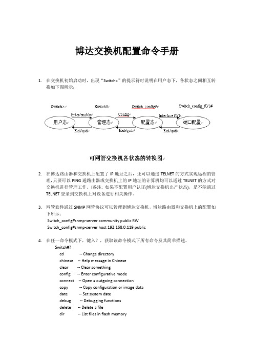
博达交换机配置命令手册1.在交换机初始启动时,出现“Switch>”的提示符时说明在用户态下,各状态之间相互转换如下图所示:2.在博达路由器和交换机上配置了IP地址之后,还可以通过TELNET的方式实现远程的管理,只要可以PING通路由器或交换机上的IP地址的计算机均可以通过TELNET的方式对交换机进行管理工作。
[备注: 如果不配置用户认证(博达交换机出产状态),是不能通过TELNET登录到交换机上对设备进行相关操作。
3.网管软件通过SNMP网管协议可以管理到博达交换机,博达路由器和交换机上的配置如下所示:Switch_config#snmp-server community public RWSwitch_config#snmp-server host 192.168.0.119 public4.在任一命令模式下,键入?,获取该命令模式下所有命令及其简单描述。
Switch#?cd -- Change directorychinese -- Help message in Chineseclear -- Clear somethingconfig -- Enter configurative modeconnect -- Open a outgoing connectioncopy -- Copy configuration or image datadate -- Set system datedebug -- Debugging functionsdelete -- Delete a filedir -- List files in flash memory5.键入一命令,后接以空格分隔的?,列出该位置下所有的关键字或参数。
Switch#show ?aaa -- Show AAA informationaggregator-group -- Link Aggregation informationalias -- Alias for commandarp -- ARP tablebreak -- Switch breakpoint informationcluster -- Cluster informationconfiguration -- Show configuration in flash memorydebug -- State of each debugging optiondot1x -- IEEE 802.1X informationhosts -- Host tableinterface -- Interface status and configurationip -- IP Configuration information……6.键入一字符串,后紧接?,列出以该字符串打头的所有命令。
博达6810交换机配置详解
line vty 4
exec-timeout 300
!
!
!
!
interface GigaEthernet8/6
!
interface GigaEthernet8/7
!
interface GigaEthernet8/8
!
interface GigaEthernet8/9
!
interface GigaEthernet8/10
switchport pvid 1001
!
!
!
interface Null0//空接口,默认就有的配置
!
interface GigaEthernet5/0//5槽位的千兆0口
no ip address
no ip directed-broadcast
!
!!slot 7 24
interface GigaEthernet7/1// 7槽位千兆1口
switchport mode trunk
!
interface GigaEthernet7/19
switchport mode trunk
!
interface GigaEthernet7/20
switchport mode trunk
!
interface GigaEthernet7/21
switchport mode trunk
!
vlanXXXX-XXXX//交换机上已创建的VLAN,VLAN创建后才可以被trunk透传
!
!
no ip igmp-proxy enable
!
!
!
!
!
!
ip route defaultX.X.X.X//为管理地址添加网关,指向城市热点内网口
博达交换机基础配置

基础配置目录第1章系统管理配置 (1)1.1 配置文件管理 (1)1.1.1 文件系统的管理 (1)1.1.2 文件系统命令 (1)1.1.3 手工从某一文件中启动 (1)1.1.4 软件更新 (2)1.1.5 配置更新 (4)1.1.6 使用ftp进行软件和配置的更新 (4)1.2 基本系统管理配置 (5)1.2.1 配置以太网IP地址 (5)1.2.2 配置缺省路由 (6)1.2.3 利用PING测试网络连通状态 (6)1.3 HTTP配置 (7)1.3.1 HTTP配置 (7)1.3.2 http配置示例 (8)第2章配置终端 (9)2.1 VTY配置概述 (9)2.2 配置任务 (9)2.2.1 线路和接口之间的关系 (9)2.3 监视与维护 (9)2.4 VTY配置举例 (10)第3章网络管理配置 (11)3.1 配置SNMP (11)3.1.1 概述 (11)3.1.2 SNMP配置任务 (12)3.1.3 配置实例 (16)3.2 配置RMON (17)3.2.1 RMON配置任务 (17)3.3 配置PDP (20)3.3.1 概述 (20)3.3.2 PDP配置任务 (20)3.3.3 PDP配置实例 (22)第4章 SSH 配置命令 (23)4.1 SSH概述 (23)4.1.1 SSH server (23)4.1.2 SSH client (23)4.1.3 实现特性 (23)4.2 配置任务 (23)4.2.1 配置认证方法列表 (23)4.2.2 配置访问列表 (23)4.2.3 配置认证超时时长 (24)4.2.4 配置认证重试次数 (24)4.2.5 使能ssh server (24)4.3 Ssh server配置示例 (24)4.3.1 访问控制列表 (24)4.3.2 全局配置 (24)第1章系统管理配置1.1 配置文件管理1.1.1 文件系统的管理FLASH中文件的名字最长只能有20个字符,且不区分大小写。
ONU配置和博达交换机配置

一,拓扑图二,ONU配置修改端口的VLAN模式,默认为“透传模式”。
模式说明如下:透传模式:不管进出端口的数据包带不带标签,对数据包不进行任何打标或剥标签操作,类似交换机的TRUNK口。
下联带VLAN的交换机时采用此模式。
Tagged模式:Tagged模式下端口需指定一个vlan id,数据包进入ONU端口时打上vlan id标签,数据包离开端口时剥离vlan id标签,类似交换机的ACCESS口。
下联PC机或HUB时采用此种模式。
LAN1:全透传vlan15,vlan40,vlan1001,类似交换机的trunk模式。
LAN3:设置vlan1001非透传模式(tagged模式),可以直接接PC,路由器。
(LAN3的配置按照华为ONU ,MAC:9017AC1EDD11的lan3口配置)三,交换机配置GTNZB1FDBJF_config#show running-configBuilding configuration...Current configuration:!!version 2.1.0A build 5721service timestamps log dateservice timestamps debug date!hostname GTNZB1FDBJF!ip default-gateway 61.133.131.65!spanning-tree mode rstp!aaa authentication login default local aaa authentication enable default none !username admin password 0 12345!interface FastEthernet0/1switchport trunk vlan-allowed 15,1001 switchport trunk vlan-untagged 15switchport mode trunkswitchport pvid 15poe force-power!interface FastEthernet0/2switchport trunk vlan-allowed 15,1001 switchport trunk vlan-untagged 15switchport mode trunkswitchport pvid 15poe force-power!interface FastEthernet0/3switchport trunk vlan-allowed 15,1001 switchport trunk vlan-untagged 15switchport pvid 15poe force-power!interface FastEthernet0/4switchport trunk vlan-allowed 15,1001 switchport trunk vlan-untagged 15switchport mode trunkswitchport pvid 15poe force-power!interface FastEthernet0/5switchport trunk vlan-allowed 15,1001 switchport trunk vlan-untagged 15switchport mode trunkswitchport pvid 15poe force-power!interface FastEthernet0/6switchport pvid 1001poe force-power!interface FastEthernet0/7switchport trunk vlan-allowed 15,1001 switchport trunk vlan-untagged 15switchport pvid 15poe force-power!interface FastEthernet0/8switchport trunk vlan-allowed 15,1001switchport trunk vlan-untagged 15switchport mode trunkswitchport pvid 15poe force-power!interface GigaEthernet0/1switchport trunk vlan-allowed 15,40switchport mode trunk!interface GigaEthernet0/2switchport trunk vlan-allowed 15,40,1001 switchport pvid 1001!interface VLAN40ip address 61.133.131.76 255.255.255.240 !vlan 1,15,40,1001!四,Pinet配置Wan:DHCP客户端模式Lan:开启DHCP。
博达交换机VLAN隔离配置[S3224]
![博达交换机VLAN隔离配置[S3224]](https://img.taocdn.com/s3/m/20a1219951e79b89680226d2.png)
博达交换机VLAN隔离配置[S3224]Switch_config#show runBuilding configuration...Current configuration:!service timestamps log dateservice timestamps debug date!!interface FastEthernet0/1 //端口1switchport mode trunk //设定成trunk模式,允许端口属于多个vlan switchport pvid 2 //数据入端口时加上vlan1的tagswitchport trunk vlan-allowed 1,24 //端口可以属于vlan1和24switchport trunk vlan-untagged 1,24 //数据出端口时去除tag1和tag24!interface FastEthernet0/2 //端口2switchport mode trunk //设定成trunk模式switchport pvid 2 //数据入端口时加上vlan2的tagswitchport trunk vlan-allowed 2,24 //端口同时可属于vlan2和24switchport trunk vlan-untagged 2,24 //数据出端口时去除tag2和tag24!interface FastEthernet0/3 //同上switchport mode trunkswitchport pvid 3switchport trunk vlan-allowed 3,24switchport trunk vlan-untagged 3,24 !interface FastEthernet0/4switchport mode trunkswitchport pvid 4switchport trunk vlan-allowed 4,24 switchport trunk vlan-untagged 4,24 !interface FastEthernet0/5switchport mode trunkswitchport pvid 5switchport trunk vlan-allowed 5,24 switchport trunk vlan-untagged 5,24 !interface FastEthernet0/6switchport mode trunkswitchport pvid 6switchport trunk vlan-allowed 6,24 switchport trunk vlan-untagged 6,24 !interface FastEthernet0/7switchport mode trunkswitchport pvid 7switchport trunk vlan-allowed 7,24 switchport trunk vlan-untagged 7,24 !interface FastEthernet0/8switchport mode trunkswitchport pvid 8switchport trunk vlan-allowed 8,24 switchport trunk vlan-untagged 8,24 !interface FastEthernet0/9switchport mode trunkswitchport pvid 9switchport trunk vlan-allowed 9,24 switchport trunk vlan-untagged 9,24 !interface FastEthernet0/10switchport mode trunkswitchport pvid 10switchport trunk vlan-allowed 10,24 switchport trunk vlan-untagged 10,24 !interface FastEthernet0/11switchport mode trunkswitchport pvid 11switchport trunk vlan-allowed 11,24 switchport trunk vlan-untagged 11,24 !interface FastEthernet0/12switchport mode trunkswitchport pvid 12switchport trunk vlan-allowed 12,24 switchport trunk vlan-untagged 12,24 !interface FastEthernet0/13switchport mode trunkswitchport pvid 13switchport trunk vlan-allowed 13,24 switchport trunk vlan-untagged 13,24 !interface FastEthernet0/14switchport mode trunkswitchport pvid 14switchport trunk vlan-allowed 14,24 switchport trunk vlan-untagged 14,24 !interface FastEthernet0/15switchport mode trunkswitchport pvid 15switchport trunk vlan-allowed 15,24 switchport trunk vlan-untagged 15,24 !interface FastEthernet0/16switchport mode trunkswitchport pvid 16switchport trunk vlan-allowed 16,24switchport trunk vlan-untagged 16,24 !interface FastEthernet0/17switchport mode trunkswitchport pvid 17switchport trunk vlan-allowed 17,24 switchport trunk vlan-untagged 17,24 !interface FastEthernet0/18switchport mode trunkswitchport pvid 18switchport trunk vlan-allowed 18,24 switchport trunk vlan-untagged 18,24 !interface FastEthernet0/19switchport mode trunkswitchport pvid 19switchport trunk vlan-allowed 19,24 switchport trunk vlan-untagged 19,24 !interface FastEthernet0/20switchport mode trunkswitchport pvid 20switchport trunk vlan-allowed 20,24 switchport trunk vlan-untagged 20,24 !interface FastEthernet0/21switchport mode trunkswitchport pvid 21switchport trunk vlan-allowed 21,24switchport trunk vlan-untagged 21,24!interface FastEthernet0/22switchport mode trunkswitchport pvid 22switchport trunk vlan-allowed 22,24switchport trunk vlan-untagged 22,24!interface FastEthernet0/23switchport mode trunkswitchport pvid 23switchport trunk vlan-allowed 23-24switchport trunk vlan-untagged 23-24!interface FastEthernet0/24 //端口24,本例中作为上行口switchport mode trunk //设为trunk模式switchport pvid 24 //数据入端口时加上vlan24的tagswitchport trunk vlan-untagged all //数据出端口时去除所有tag(tag1~tag24)! //注意trunk口时默认属于所有tag的!vlan 1-24 //建立1~24个vlan,默认情况下只有vlan1,其他需要增加,且这个操作时第一步要做的!!!说明,本例子完成之后,interface f0/1~f/23分别属于不同的vlan,相互之间是不能互通的(不考虑使用三层路由转发的情况),但此时这23个端口都能与上行口interface f0/24口通讯!此时的vlan分配情况为:Switch_config#show vlanVLAN Status Name Ports---- ------- -------------------------------- ---------------------------------1 Static Default F0/1, F0/242 Static VLAN0002 F0/2, F0/243 Static VLAN0003 F0/3, F0/244 Static VLAN0004 F0/4, F0/245 Static VLAN0005 F0/5, F0/246 Static VLAN0006 F0/6, F0/247 Static VLAN0007 F0/7, F0/248 Static VLAN0008 F0/8, F0/249 Static VLAN0009 F0/9, F0/2410 Static VLAN0010 F0/10, F0/2411 Static VLAN0011 F0/11, F0/2412 Static VLAN0012 F0/12, F0/2413 Static VLAN0013 F0/13, F0/2414 Static VLAN0014 F0/14, F0/2415 Static VLAN0015 F0/15, F0/2416 Static VLAN0016 F0/16, F0/2417 Static VLAN0017 F0/17, F0/2418 Static VLAN0018 F0/18, F0/2419 Static VLAN0019 F0/19, F0/2420 Static VLAN0020 F0/20, F0/2421 Static VLAN0021 F0/21, F0/2422 Static VLAN0022 F0/22, F0/2423 Static VLAN0023 F0/23, F0/2424 Static VLAN0024 F0/1, F0/2, F0/3, F0/4, F0/5F0/6, F0/7, F0/8, F0/9, F0/10F0/11, F0/12, F0/13, F0/14, F0/15F0/16, F0/17, F0/18, F0/19, F0/20F0/21, F0/22, F0/23, F0/24简单分析一下工作流程:1、f0/2和f0/3之间的通信,Switch_config#show vlan inter f0/2Interface VLANName Property PVID Vlan-Map uTagg-VLan-Map-------------------- -------- ---- ---------------- ----------------FastEthernet0/2 Trunk 2 2,24 2,24Switch_config#show vlan inter f0/3Interface VLANName Property PVID Vlan-Map uTagg-VLan-Map-------------------- -------- ---- ---------------- ----------------FastEthernet0/3 Trunk 3 3,24 3,24从中我们可以看到,f0/2是属于vlan2和vlan的,且pvid为2,那就是说普通数据(非802.1q)进入这个端口时会被打上tag2,然后zhge报通过交换机到达f0/3时,端口三是指能够untagvlan3和vlan24的的tag的,这个可以从上面的show vlan inter f0/3看出来,所以f0/3无法识别从f0/2过来的数据包!反过来也是一样的!换句话说就是实现了vlan2和vlan3的隔离!2、f0/2和f0/24之间的通信,Switch_config#show vlan inter f0/2Interface VLANName Property PVID Vlan-Map uTagg-VLan-Map-------------------- -------- ---- ---------------- ----------------FastEthernet0/2 Trunk 2 2,24 2,24Switch_config#show vlan inter f0/24Interface VLANName Property PVID Vlan-Map uTagg-VLan-Map-------------------- -------- ---- ---------------- ----------------FastEthernet0/24 Trunk 24 1-24 1-2同上面的分析方法,f0/2进入的数据被打上了tag2,但是由于f0/24是untag all的,所以他能够去除tag2,或者是识别vlan2的数据!反过来也是一样,数据进入f0/24时打上了tag24,这个标记在f0/2口上是能够被去除的!所以f0/2口和f0/24口可以实现互通!上面的两个通信过程基本代表了这种vlan配置/应用的功能,即:所有的下行口都能相互隔离,但是所有的下行口都能与上行口通讯!这种vlan配置方式比较简单,也非常常用!大家可以参考应用!当然这种方式的vlan划分是局限在一台交换机上面的!一般情况下在中小规模的应用中比较常见,特点是完全由一台交换机来实现vlan的隔离/互通,且每一个端口的输出数据都是不带有tag的,是普通的ip数据包,用户绝大多数的数据设备都能识别!(一般的网卡是无法识别802.1q的数据包的)还有一个优点是,这个交换机上面使用过的vlan号在其他交换机上面可以重复使用,没有限制或者相关性!还有一种应用是跨交换机的vlan配置!这种方式下要考虑多台交换机的相互协调工作,比如vlan tag的“加和“去”的问题!还是以实现上面例子为例,Switch_config#show run Building configuration... Current configuration:!service timestamps log date service timestamps debug date !!interface FastEthernet0/1!interface FastEthernet0/2switchport pvid 2!interface FastEthernet0/3switchport pvid 3!interface FastEthernet0/4switchport pvid 4!interface FastEthernet0/5switchport pvid 5!interface FastEthernet0/6switchport pvid 6!interface FastEthernet0/7 switchport pvid 7!interface FastEthernet0/8 switchport pvid 8!interface FastEthernet0/9 switchport pvid 9!interface FastEthernet0/10 switchport pvid 10!interface FastEthernet0/11 switchport pvid 11!interface FastEthernet0/12 switchport pvid 12!interface FastEthernet0/13 switchport pvid 13!interface FastEthernet0/14 switchport pvid 14!interface FastEthernet0/15 switchport pvid 15!interface FastEthernet0/16 switchport pvid 16!interface FastEthernet0/17 switchport pvid 17!interface FastEthernet0/18 switchport pvid 18!interface FastEthernet0/19 switchport pvid 19!interface FastEthernet0/20 switchport pvid 20!interface FastEthernet0/21 switchport pvid 21!interface FastEthernet0/22 switchport pvid 22!interface FastEthernet0/23 switchport pvid 23!interface FastEthernet0/24switchport mode trunkswitchport trunk vlan-untagged all!vlan 1-24!!在这个配置里面,我们可以看到,除了上行口之外,所有的端口都属于access模式,就是说端口只是属于一个vlan,而f0/24上行口虽然和前面一样都是trunk,但是没有必要指定pvid号,原因是因为在这个配置里面这个参数不是很重要!因为下行口的数据网上走时,相应的tag都能被f0/24识别(tag号不去除),但下行数据打上什么tag就不是f0/24来确定了,这个参数多是由对方交换机来确定的或者是由对方路由器(封装子接口,802.1q)来确定的!这第二种方式,关于对方的配置情况就比较复杂:1、如果是博达自己的交换机,那么配置就相对简单,方法如前所述;最简单的配是:两台BDCOM交换机按照楼上的配置即可实现vlan的相互隔离和通信,方法是把他们的f0/24口连接起来即可,然后即可实现两台交换机的号码相同的口互通,号码不同的口不能通信!2、如果对方是支持802.1q的路由器,比如BDCOM的2621路由器,在其子接口下面封装相应的vlan即可!如:interface FastEthernet0/0.1ip address *.*.*.*no ip directed-broadcastencapsulation dot1Q 2bandwidth 100000delay 1!interface FastEthernet0/0.2ip address *.*.*.*no ip directed-broadcastencapsulation dot1Q 3bandwidth 100000delay 1!interface FastEthernet0/0.3ip address *.*.*.*no ip directed-broadcastencapsulation dot1Q 4bandwidth 100000delay 1!3、如果对方是其他厂家的设备,基本上也是支持这种情况,但命令就不尽相同了。
华为博达交换机路由器配置方法

all All
[Quidway-Ethernet0/0/1]quit
[Quidway]dis vlan 2 显示VLAN 内所加入到端口
* : management-vlan
VLAN ID TypeStatus MAC Learning Broadcast/Multicast/Unicast Property
interface FastEthernet0/23
interface FastEthernet0/24
interface GigaEthernet0/1
interface GigaEthernet0/2
vlan 1-2
Switch_config#write配置完成后进入编辑模式<保存当前配置>
五、博达路由器配置手册
remove -- 从当前范围表中删除VLAN表
all -- 所有的VLAN
none -- 没有VLAN
Switch_config_f0/1#quit退出进入
Switch_config_f0/2#switchport mode access进入端口2该为acces 模式
Switch_config_f0/2#switchport pvid 2把2端口加入VLAN 2
Router_config_f0/0#ip nat inside——定义该端口为NAT内部接口
Router_config_f0/0#no shutdown——配置完成后启动该端口
Router_config_f0/0#quit——退出该端口
2
Router_config#interface fastEthernet 0/1——进入0/1端口下面
博达交换机简易配置方法

博达交换机简易配置方法 Last updated on the afternoon of January 3, 2021上海博达交换机基本配置介绍1.Console口的登录通过超级终端的方式登陆交换机进行管理配置,如下步骤截图:如何先打开超级终端:打开“开始”菜单-----“所有程序”-----“附件”-----“通讯”-----“超级终端”新建连接名称为任意,如下图:选择正确的COM口,这里是COM3,不同的PC可能不同的COM口号,选择你PC 连接到交换机的正确COM口,如下图:设置COM口的属性,这里只要点击还原为默认值即可,如下图:点击确定后,确定后进入配置界面,进入后多按几次回车,如下图:以上为交换机CONSOLE口的登录方式。
2.交换机VLAN的划分刚开始登陆交换机时候,该交换机只是处于用户模式,如果需要配置交换机需要进入配置模式下,如下命令:bdcom>换机端口保护功能在正常情况下,交换机的不通端口间的数据包能够自由的转发。
在某些情况下,需要禁止端口之间的数据流,端口隔离功能就是提供这种控制的,设置隔离功能的端口之间不能够再有数据包通信,其他没有隔离的端口之间以及隔离端口和未隔离端口之间的数据包仍然能够正常转发。
配置实例:将F0/1和F0/2端口隔离:switch_config_f0/1#switchportprotectedswitch_config_f0/1#interfacefastEthernet0/2switch_config_f0/2#switchportprotected端口F0/1和F0/2之间就不能相互通信,如果F0/1端口有ARP广播欺骗也不会影响到F0/2。
比如F0/3端口没有划分成端口保护,F0/1与F0/2端口都可以与F0/3口通信。
提示:与路由器相连接的端口不能启用端口隔离功能。
4.交换机配置用户名和密码如果交换机登陆时候需要用户名和密码验证,如下命令:switch_config#usernamebdcompasswordbdcomswitch_config#aaaauthenticationlogindefaultlocalswitch_config#aaaauthenticationenabledefaultnone配置如上三条命令后,交换机的登陆用户名和密码为bdcom5.交换机典型配置模式典型配置Switch>enableSwitch#configSwitch_config#interfacefastEthernet0/1//进入f0/1口进行配置switch_config_f0/1#switchportmodetrunk//配置f0/1口为trunk口做为上连口swicth_config_f0/1#interfacerangefastEthernet0/2–8//将f0/2-8口这7个口同时进行配置Switch_config_if_range#switchportpvid2//将f0/2–8口配置成vlan2Switch_config_if_range#exit//退回到配置模式Switch_config#write//保存配置配置完成!交换机登陆用户名密码以及端口保护功能根据情况进行配置。
博达交换机配置说明

博达交换机常用功能配置提示符状态定义Switch>用户模式(enable命令进入特权模式)Switch#特权模式(Config命令进入全局配置模式)Switch_config#全局配置模式Switch_config_f0/1#端口配置模式常用命令:1、AAA认证Enable密码认证必设、登录密码认证和line密码认证二选一全局配置模式下:(1)设置登录密码认证aaa authentication login default localusername bdcom password bdcom(2)设置enable密码认证aaa authentication enable default enableenable password bdcom(3)设置line密码认证aaa authentication login default line!line console 0password bdcom!line vty 0 4password bdcom!(4)密码加密service password-encryption2、Radius认证全局配置模式下设置对登录用户进行Radius认证aaa authentication login default group radius设置Radius服务器:radius-server host 192.168.1.1 auth-port 1812 acct-port 1813 设置Radius Key:radius-server key bdcom3、生成树全局配置模式spanning-tree mode sstpspanning-tree mode rstpspanning-tree mode mstp相关查看命令show spanning-tree4、Logging日志全局配置模式(关闭)开启日志功能(缺省开启)(no)logging on记录日志到服务器logging 192.168.1.1记录日志到本地缓冲区(机器重启后消失)logging buffered 4096005、VLAN全局模式,创建VLANVlan 1-10,15,20-30进入端口模式,将端口加入某个VLAN interface FastEthernet0/1switchport pvid 10!查看命令:Show vlan6、端口模式全局模式下,进入端口模式,配置端口为802.1Q Trunk模式interface FastEthernet0/1switchport mode trunk!全局模式下,进入端口模式,配置端口为802.1Q Access模式(交换机端口缺省配置)interface FastEthernet0/1switchport mode access!7、邻居发现协议全局模式,启用CDP协议查看邻居:show pdp neighbor8、广播、组播风暴抑制端口配置模式(500个包每秒)storm-control broadcast threshold 500storm-control multicast threshold 500思科的配置:端口下配置,端口带宽的百分比>> storm-control broadcast level 1.00>> storm-control multicast level 1.00按照100Mbps的1%计算即1Mbps,250Kbytes/s,按照一个报文500字节平均长度计算,就是500个包/秒9、端口环路检测全局模式:设置端口检测到环路shutdown之后,30秒钟端口重启动errdisable-recover keepalive interval 30端口模式,开启keepalive端口环路检测功能Keepalive (0-32767秒,缺省12秒)10、交换机命名全局模式hostname BDCOM_S202611、端口保护全局模式下switchport protected注:配置了该命令的端口之间不能互相访问。
- 1、下载文档前请自行甄别文档内容的完整性,平台不提供额外的编辑、内容补充、找答案等附加服务。
- 2、"仅部分预览"的文档,不可在线预览部分如存在完整性等问题,可反馈申请退款(可完整预览的文档不适用该条件!)。
- 3、如文档侵犯您的权益,请联系客服反馈,我们会尽快为您处理(人工客服工作时间:9:00-18:30)。
博达交换机测试补充配置说明上海博达数据通信有限公司2004年3月24日目录1、基本配置41.1Console口本地配置41.2基本配置命令41.3Console配置口密码设置51.4enable密码设置51.5Telnet用户&密码配置51.6限制Telnet到交换机上来的IP地址61.7Web管理61.8SNMP网管软件管理81.9中英文提示91.10TFTP软件升级、Zmodem协议升级91.11Syslog日志功能91.12DHCP Server功能91.13SNTP时间协议101.14Ping & Traceroute工具102、VLAN配置112.1 Cisco PVLAN概念及博达实现112.2华为PVLAN概念及博达实现142.3博达SuperVLAN配置162.4 Protected Port保护端口172.5 GVRP配置172.6生成树协议182.7安全端口183、路由协议183.1 RIP183.2 OSPF193.3 EIGRP193.4 BGP20四、网络安全204.1端口镜像204.2 802.1X认证214.3 ACL访问控制234.4 IP地址、MAC地址与端口的绑定244.5端口限定MAC地址数254.6 AAA & Radius、Tacacs+认证254.7 NAT功能25五、QoS265.1 CoS & 802.1P265.2 基于策略的QoS275.3拥塞控制275.4广播风暴抑制285.5带宽控制& 端口限速& 基于策略的限速28六、网络管理306.1 CLI命令行306.2 Telnet远程登录306.3 TFTP远程配置上传下载306.4 Web管理306.5 SNMP网络管理306.6集群管理30七、组播317.1 IGMP Snooping317.2组播路由协议31八、可靠性31端口汇聚功能311、基本配置1.1 Console口本地配置PC串口速率9600,数据位8,奇偶校验无,停止位1,数据流控无。
PC串口属性设置:1.2 基本配置命令用户态:Switch>enable管理态:Switch#config全局配置态:Switch_config# interface FastEthernet0/1端口配置状态:Switch_config_f0/1#enableconfig terminalinterface FastEthernet0/1show runningshow configshow version (all)show cpushow memory (mblk/ dead)……1.3 Console配置口密码设置全局配置态下命令设置:!line console 0password bdcom //设置Console口配置口令!service password-encryption //口令MD5加密aaa authentication login default line //用line密码进行认证!1.4 enable密码设置全局配置态下命令设置:enable password bdcom //设置enable密码service password-encryption //口令MD5加密1.5 Telnet用户&密码配置全局配置态下命令设置:line vty 0password 1234!user bdcom password abcd //添加用户名bdcom,口令abcdservice password-encryption //口令MD5加密aaa authentication login default line //用line密码进行认证aaa authentication login default local //用本地数据库中用户名和密码进行认证1.6 限制Telnet到交换机上来的IP地址全局配置态下命令设置:!ip access-list standard 1 //定义访问列表1permit 192.168.1.111 255.255.255.255 //允许192.168.1.111!ip telnet access-class 1 //引用访问列表1,只允许list 1中的IP地址telnet 上来1.7 Web管理PC通过IE浏览器实现对交换机的Web页面管理。
全局配置态下命令设置:ip http serverBDCOM S2224二层交换机Web页面管理图BDCOM S3224三层交换机Web页面管理图1.8 SNMP网管软件管理博达交换机配置SNMP,可以通过各种通用网管软件进行管理,如博达的BroadDirector、Cisco的Ciscoworks、HP的OpenView、SNMPc等网管软件。
通过网管软件进行管理非常直观,可以看到交换机的背板、各端口工作状态、数据统计信息等等。
全局配置态下命令设置:!snmp-server community public RWsnmp-server host 192.168.1.1 publicsnmp-server trap-source VLAN1!1.9 中英文提示任意状态下命令设置:Chinese //中文提示English //英文提示1.10 TFTP软件升级、Zmodem协议升级管理态下命令:dir //看当前文件目录列表、剩余空间等copy t 192.168.1.1 //从T 192.168.1.1取文件到本地flash copy flash t //从本地flash拷贝文件到T1.11 Syslog日志功能全局配置态下命令设置:logging 192.168.1.1logging trap warningslogging source-interface vlan 11.12 DHCP Server功能三层交换机支持该功能。
全局配置态下命令设置:!ip dhcpd pool 1network 192.168.1.0 255.255.255.0range 192.168.1.150 192.168.1.250default-router 192.168.1.254dns-server 202.101.172.35 202.101.172.36netbios-name-server 202.101.172.35 202.101.172.36 !ip dhcpd enable!1.13SNTP时间协议博达交换机与网络中SNTP 或NTP Server时钟源同步。
全局配置态下命令设置:sntp server 192.168.1.11.14 Ping & Traceroute工具博达提供功能完善的ping功能。
Ping参数如下:-a -- 一直ping,直到被中断-d -- 不使用路由表,直接路由到端口-f -- 在IP报头中设置DF标志位-i -- 报文使用的源地址-m -- 报文指定端口的地址-j -- 松弛源路由-k -- 严格源路由-l -- 数据长度-n -- 发送的echo请求报文数-r -- 记录路由-s -- TOS-t -- TTL-v -- 详细的输出信息-w -- 等待应答的时间(秒)-b -- 两个Ping 报文之间的时间间隔(10ms)WORD -- 目的地址或主机名Traceroute参数如下:-i -- 报文使用的源地址-m -- 报文使用的指定端口的地址-j -- 松弛源路由-k -- 严格源路由-p -- 端口号-q -- 每一跳的探测帧数-r -- 记录路由-t -- TTL-w -- 等待应答的时间(秒)-x -- 使用UDP之外的协议WORD -- 目的地址或主机名2、VLAN配置VLAN的实现有基于802.1Q、端口等等之分。
从功能上,不同的厂家有不同的实现,如Cisco的PVLAN、华为的PVLAN,博达和华为的SuperVLAN等等。
Cisco和华为的PVLAN名称相同但概念含义具体有所不同。
2.1 Cisco PVLAN概念及博达实现Cisco PVLAN把端口分为了以下三种模式:Promiscuous port:处于Primary VLAN中的端口为Promiscuous port,可以和任何Community port、Isolated port和Promiscuous port通信。
Community port:处于Community VLAN中的端口为Community port,只能和Community port和Promiscuous port通信。
Isolated port:处于Isolated VLAN中的端口为Isolated port,只能和Promiscuous port通信(不能和其它任何种类的的端口通信)。
实际上PVLAN并不是一个单独的技术,而只是把一些VLAN的常规配置方法,进行了一个批处理。
让配置可以来的更简单些。
我们的交换机现在没有专门针对PVLAN的命令。
而可以通过对VLAN的一系列配置,而达到最终和PVLAN 一致的效果。
(这里我们也要明确一点,处于Cisco PVLAN中的端口,向外发送数据全部是Untag的。
不能带Tag标记)Client A和B属于Primary VLAN;Clinet C和D属于Community VLAN;Client E和F属于Isolated VLAN;按PrivateVLAN定义,A、B、C、D能相互交换,E和F不能相互交换;E 能和A、B进行交换,F能和A、B进行交换;E不能和C、D进行交换,F也不能和C、D进行交换。
博达交换机实现Cisco PVLAN配置:!interface FastEthernet0/1switchport mode trunkswitchport trunk vlan-untagged 1-4switchport shared-learning!interface FastEthernet0/2 switchport mode trunkswitchport trunk vlan-untagged 1-4 switchport shared-learning!interface FastEthernet0/3 switchport mode trunkswitchport pvid 2switchport trunk vlan-untagged 1-4 switchport trunk vlan-allowed 1-2 switchport shared-learning!interface FastEthernet0/4 switchport mode trunkswitchport pvid 2switchport trunk vlan-untagged 1-4 switchport trunk vlan-allowed 1-2 switchport shared-learning!interface FastEthernet0/5 switchport mode trunkswitchport pvid 3switchport trunk vlan-allowed 1,3 switchport trunk vlan-untagged 1-4 switchport shared-learning!interface FastEthernet0/6 switchport mode trunkswitchport pvid 4switchport trunk vlan-allowed 1,4switchport trunk vlan-untagged 1-4switchport shared-learning!interface FastEthernet0/7!……!interface FastEthernet0/24!vlan 1,42.2华为PVLAN概念及博达实现华为PVLAN它的功能是在小区接入中,通过将用户划入不同的VLAN,实现用户之间二层报文的隔离。