欧米茄表使用说明书
欧米茄表使用说明书
如何确定我购买的是正宗欧米茄腕表?遵循如下步骤可以确定您购买的是正宗欧米茄腕表:- 只在欧米茄指定经销商处购买欧米茄腕表。
- 申请一张信用卡大小的保修卡,完整填写8位系列编号、手表编号以及经销商的完整姓名和地址。
- 如果您想确定腕表是否正宗,请携同欧米茄腕表及保修卡到指定的维修中心,让我们的维修服务员确定您购买的是否为正宗欧米茄腕表。
客户服务网络返回页首计时表(CHRONOGRAPH)与瑞士官方天文台认证腕表(CHRONOMETER)有何区别?计时表(CHRONOGRAPH)带有显示时、分和秒的指针,它们与机械系统一起透过中央计时指针测定逝去时间,可以记录到秒,并且具有30分钟和12小时定时装置。
瑞士官方天文台认证腕表(CHRONOMETER)是以不同角度,成功通过温度、精确度和防水功能测试后,获得COSC(瑞士官方天文台)正式颁发的等级证书的腕表。
通过这些测试至少需要15天时间。
返回页首计时腕表上的按钮具有什么功能?位于2点钟位置的按钮可以启动或停止计时功能,位于4点钟位置的按钮用于重新计时。
返回页首海马系列专业计时腕表的排氦气阀门具有什么功能?排氦气阀门由欧米茄为职业潜水员专门研发。
在深海潜水过程中,潜水员往往会在潜水钟内进行数天作业。
在到达水平面之前,潜水钟内充满氦气和氧气的混合气体。
氦气分子轻于空气,可以渗入手表,并在大气压力的作用下将水晶镜面推出。
在到达水平面之前打开氦气排放阀可以将氦气排放,从而防止手表进水。
返回页首自动上链机芯与手动上链机芯有何区别?自动上链机芯与手动上链机芯的区别在于上链方式的不同。
手动上链腕表需要每天人工上链,而自动上链腕表则具有内部摩打,利用手腕的运动来自动上链。
自动上链腕表通常具有至少40小时的动力储存,即使不佩戴手表,仍然能够备有足够的能量储存以保持稳定的运行。
返回页首欧米茄腕表是否具有防振功能?是。
欧米茄腕表可以承受重量为5000克的振动。
返回页首欧米茄腕表是否具有防磁性能?是。
Omega 运动表产品说明书
WARRANTY/DISCLAIMEROMEGA ENGINEERING, INC. warrants this unit to be free of defects in materials and workmanship for a period of 13 months from date of purchase. OMEGA’s WARRANTY adds an additional one (1) month grace period to the normal one (1) year product warranty to cover handling and shipping time. T his ensures that OMEGA’s customers receive maximum coverage on each product.If the unit malfunctions, it must be returned to the factory for evalua-tion. OMEGA’s Customer Service Department will issue an Authorized Return (AR) number immediately upon phone or written request.Upon examination by OMEGA, if the unit is found to be defective, it will be repaired or replaced at no charge. OMEGA’s WARRANTY does not apply to defects resulting from any action of the purchaser, including but not limited to mishandling, improper interfacing, opera-tion outside of design limits, improper repair, or unauthorized modifi-cation. This WARRANTY is VOID if the unit shows evidence of having been tampered with or shows evidence of having been damaged as a result of excessive corrosion; or current, heat, moisture or vibration; improper specification; misapplication; misuse or other operating conditions outside of OMEGA’s control. Components in which wear is not warranted, include but are not limited to contact points, fuses, and triacs.OMEGA is pleased to offer suggestions on the use of its vari-ous products. However, OMEGA neither assumes responsibil-ity for any omissions or errors nor assumes liability for any damages that result from the use if its products in accordance with information provided by OMEGA, either verbal or writ-ten. OMEGA warrants only that the parts manufactured by the company will be as specified and free of defects. OMEGA MAKES NO OTHER WARRANTIES OR REPRESENTATIONS OF ANY KIND WHATSOEVER, EXPRESSED OR IMPLIED, EXCEPT THAT OF TITLE, AND ALL IMPLIED WARRANTIES INCLUDING ANY W ARRANTY OF MERCHANTABILITY AND FITNESS FOR A PARTICULAR PURPOSE ARE HEREBY DISCLAIMED. LIMITATION OF LIABILITY: The remedies of purchaser set forth herein are exclusive, and the total liability of OMEGA with respect to this order, whether based on contract, warran-ty, negligence, indemnification, strict liability or otherwise, shall not exceed the purchase price of the component upon which liability is based. In no event shall OMEGA be liable for consequential, incidental or special damages.CONDITIONS: Equipment sold by OMEGA is not intended to be used, nor shall it be used: (1) as a “Basic Component” under 10 CFR 21 (NRC), used in or with any nuclear installation or activity; or (2) in medical appli-cations or used on humans. Should any Product(s) be used in or with any nuclear installation or activity, medical application, used on humans, or misused in any way, OMEGA assumes no responsibility as set forth in our basic WARRANTY/DISCLAIMER language, and, additionally,purchaser will indemnify OMEGA and hold OMEGA harmless from any liability or damage whatsoever arising out of the use of the Product(s)in such a manner.RETURN REQUESTS/INQUIRIESDirect all warranty and repair requests/inquiries to the OMEGA Customer Service Department. BEFORE RE URNING ANY PRODUC (S) O OMEGA, PURCHASER MUS OB AIN AN AUTHORIZED RETURN (AR) NUMBER FROM OMEGA’S CUSTOMER SERVICE DEPART MENT (IN ORDER T O AVOID PROCESSING DELAYS). T he assigned AR number should then be marked on the outside of the return package and on any correspondence.FOR WARRANTY RETURNS, please have the following information available BEFORE contacting OMEGA:1. Purchase Order numberunder which the product was PURCHASED, 2. Model and serial number of the product under warranty, and 3. Repair instructions and/or specific problems relativeto the product.FOR NON-WARRANTY REPAIRS, consult OMEGA for current repair charges. Have the following information available BEFOREcontacting OMEGA:1. P urchase Order number to cover the COST of the repair or calibration,2. Model and serial number of the product, and 3. R epair instructions and/or specific problems relative to the product.OMEGA’s policy is to make running changes, not model changes, whenever an improvement is possible. This affords our customers the latest in technology and engineering.OMEGA is a trademark of OMEGA ENGINEERING, INC.© Copyright 2019 OMEGA ENGINEERING, INC. All rights reserved. T his document may not be copied, photocopied, reproduced, translated, or reduced to any electronic medium or machine-readable form, in whole or in part, without the prior written consent of OMEGA ENGINEERING, INC.MQS5749/1120GW-001-NALayer N Long Range Gateway***********************The information contained in this document is believed to be correct, butOMEGA accepts no liability for any errors it contains, and reserves the right to alter specifications without notice.Servicing North America:U.S.A. Omega Engineering, Inc.Headquarters: 800 Connecticut Ave. Suite 5N01, Norwalk, CT 06854 Toll-Free: 1-800-826-6342 (USA & Canada only)Customer Service: 1-800-622-2378 (USA & Canada only) Engineering Service: 1-800-872-9436 (USA & Canada only) Tel: (203) 359-1660 Fax: (203) 359-7700 e-mail:**************For Other Locations Visit /worldwide65This product contains software that is subject to an open source license agreement including GNU General Public License (“GPL”) or GNU Lesser General Public License (“LGPL”). With respect to the free/open source terms, customers of this product have rights to acquire, modify and redistribute the source code in accordance of the terms of the GPL and LGPL. If you have any questions or wish to receive a copy of any source code that you may be entitled under the term, please contact us at:*************************Please include SKU of this product in your request.The subject should be: GW001 GPL license statement request The original source code is available on the corresponding hosting website.GNU General Public License:https:///licenses/gpl-3.0.en.html GNU Lesser General Public License:https:///licenses/lgpl-3.0.en.htmlSafety: EN 61010-1:2010EMC: EN 301 489-1 V2.2.0 EN 301 489-3 V2.1.1Radio: EN 300 320-1 V3.1.1 EN 300 220-2 V3.1.1CE:The product herewith complies with the essentialrequirements and other relevant provisions of the Radio Equipment Directive 2014/53/EU, the EMC Directive2014/30/EU, the ROHS Directive EU 2015/863, and carries the CE-marking accordingly. Only use approved power supplies with this device.The following CE Mark is affixed to this equipment.The CE declaration is available at the website listed on the cover page of this manual.In the Web UI, you can add external accessories by clicking on th e sign. Follow the dropdown bar selections and fill out all fields as required.While your GW-001 is connected to the Internet, the Gateway UI can be accessed by typing: http://X.X.X.X (where X is the IP address of the gateway) OR by typing: 234START HEREUse this Quick Start Guide to set up your Layer N GW-001Gateway. For additional information regarding your GW-001, refer to the User Manual available on the Omega website.• Layer N GW-001 Unit • Quick Start Guide • 12 V Power Adapter • Ethernet Cable • AntennaAdditional Materials Needed• Access to an Ethernet port on your network -Network must have Internet connectivity • A registered user account with • A Layer N compatible device that will connect to the gateway• Any device with web browser accessThe GW-001 Gateway contains an internal UI that can be used to upgrade various firmwares and configure the external accessories.To setup your Layer N Gateway, you must first create and register a Layer N Cloud account. Using any device with a web browser, complete the following steps:Step 1: Open your browser to Step 2: Click Sign Up and complete the registration process.Registered Email: _________________________________New User Password: ______________________________Once your user credentials are verified, you can sign in and you will be presented with the Layer N Cloud homepage.Note: See the section below for instructions on how to create and register a Layer N Cloudaccount.Sign in to your Layer N Cloud account using any device with a web browser. Once you are logged in, register your new gateway by following these steps:Step 1: From the cloud homepage, click Add Gateway .Note: The label containing your Gateway ID and Registration ID is located on the bottom ofthe gateway unit.Step 3: Type in the Registration ID on your gateway label and click Register .Step 4: Once you have successfully registered your gateway, a icon will appear next to your registered device. You can now change the name of your gateway.Note: The icon will disappear once theregistered gateway is powered on.The GW-001 Series gateways offer the following measurement interface options:• Smart Sensor one-button pairing • 2x USB 2.0 connectors• Serial data and alarm connector • Ethernet RJ45 connectorOnce your gateway is registered to your Layer N Cloud account, follow these instructions to power on your gateway:Step 1: Connect antenna included with your gateway to the side of the Gateway housing.Your gateway can now accept connections from a Layer N Smart Sensor, wired sensors, controller devices such as TCP ModBus or Serial Modbus depending on the gateway model you have purchased.Pin Description Pin 1TX (D+)Pin 2RX (D-)Pin 3GND Pin 4Alarm (N/O)Pin 5Alarm (N/O)Serial Data and Alarm ConnectorThe 5-pin screw terminal can accept RS232 or RS485 inputs from authorized OMEGA accessories and devices such as OM240, CN6161A, and DP612. The 5-pin screw connector on the gateway is labeled as follows:Contact Omega or visit our website to see othercompatible devices.Step 2: Type in the Gateway ID.Step 6: The LED light on the Pairing Button will blink red to indicate that it is booting up.Smart Sensor PairingPairing a Layer N Smart Sensor to your Layer N Gateway is made easy with one-button pairing. Simply press the pairing button on your gateway and press the pairing button on your sensor to connect the two. Your Smart Sensor will now be visible on your Layer N Cloud interface.Note: It is recommended that you only use Layer N Cloud to upgrade firmware for theGateway.Ethernet ConnectorA second Ethernet port for Modbus TCP devices and Power over Ethernet is available on certain models.Note: Layer N GW-001 Series connectivityinterfaces vary with each model.Step 2: Connect the DC 12V adapter to the back of the gateway.Step 3: Connect the included Ethernet cable to the port labeled Ethernet 1 on the gateway.Step 4: Connect the other side of the Ethernet cable to a router or LAN that will provide Internet access.Step 5: Turn the power switch on the gateway to the ON position.Once it is connected to the Internet, the light will stay a solid green.Gateway IDRegistration IDUSB 2.0 ConnectorsThe USB 2.0 connectors are used to connect Layer NSmart Probes with an IF-001 Smart Interface Cable directly to your Gateway.I nterfaces available vary with modelImportant: Do not power on the Gateway or Smart Sensor before Gateway registration iscomplete.Step 1: Enter the password located on the label of your gateway unit.Step 2: Enter the same password from Step 1 under Existing Password , and then follow the instructions to create a new password.http://omegaiotgatewayXXXX.local(where XXXX are the last 4 digits of your Gateway MAC Address ). This will only work if your browser/computer has Bonjour Service installed. For either method, the computer and gateway must be on the same local area network.Once you have access to the gateway internal UI, you will be prompted to enter a password. Follow these instructions:。
Omega Seamaster 300M 产品说明书

An OMEGA Te c h n o l o g i e s Co m p a n y DP18 SeriesModels DP18-M1/M2RTD Input Temperature IndicatorCCD1294APC5BSPECIFICATIONSTEMPERATURE METERS FOR 100 Ω Pt RTD (Resistance Temperature Detector) INPUT DIN 43760, α =0.00385.PROVIDED WITH BUILT-IN CURRENT EXCITATION AND LINEARIZATION FOR DIRECT READOUT IN DEGREES CENTIGRADE. ACCEPT SENSORS WITH 2 OR 3 WIRES AND AUTOMATIC MAXIMUM LEAD RESISTANCE COMPENSATION IS 10 Ω. BOTH MODELS CAN ACCEPT ADDITIONAL BOARDS FOR ANALOG OUTPUT AND UPPER BOARDS FOR DIGITAL OR CONTROL OUTPUTS.FIG. 3MODEL TEMPERATURE RANGE ACCURACY RESOLUTIONMAXIMUM COMPENSATIONDP18-M1-100to+650°C1 °C ±1 1 °C DP18-M2-150.0to +199.9°C1 °C ±10.1 °C10 ΩOPTIONS AND POWER SUPPLIES AVAILABLE FOR DP18 SeriesCONTROL O UTPUT/COMMUNICATIONS O PTIONS Select a maximum of one option from each columnPOWER SUPPLY OPTIONSServicing USA and Canada: Call OMEGA Toll FreeUSA CanadaOne Omega Drive, Box 4047976 BergarStamford, CT 06907-0047Laval (Quebec) H7L 5A1Telephone: (203) 359-1660Telephone: (514) 856-6928FAX: (203) 359-7700FAX: (514) 856-6886Sales Service: 1-800-826-6342 / 1-800-TC-OMEGA SM Customer Service: 1-800-622-2378 / 1-800-622-BEST SM Engineering Service: 1-800-872-9436 / 1-800-USA-WHEN SMTELEX: 996404 EASYLINK: 62968934 CABLE: OMEGAServicing Europe: One OMEGA Drive, River BendThecnology CentreNorthbank, Irlam, ManchesterM44 5EX , EnglandTelephone: 44 (161) 777-6611 FAX: 44 (161) 777-6622RETURN REQUESTS / INQUIRIESDirect all warranty and repair requests/inquiries to the OMEGA ENGINEERING Customer Service Department. BEFORE RETURNING ANY PRODUCT(S) TO OMEGA, PURCHASER MUST OBTAIN AN AUTHORIZED RETURN (AR) NUMBER FROM OMEGA'S CUSTOMER SERVICE DEPARTMENT (IN ORDER TO AVOID PROCESSING DELAYS). The assigned AR number should then be marked on the outside of the return package and on any correspondence.OMEGA's policy is to make running changes, not model changes, whenever an improvement is possible. This affords our customers the latest in technology and engineering.OMEGA is a registered trademark of OMEGA ENGINEERING, INC.© Copyright 1998 OMEGA ENGINEERING, INC. All rights reserved. This documentation may not be copied, photocopied, reproduced, translated, or reduced to any electronic medium or machine-readable form, in whole or in part, without prior written consent of OMEGA ENGINEERING, INC.FOR WARRANTY RETURNS, please have the following information available BEFORE contacting OMEGA:1.P.O. number under which the product was PURCHASED.2.Model and serial number of the product under warranty, and3.Repair instructions and/or specific prob-lems relative to the product.WARRANTY/DISCLAIMEROMEGA warrants this unit to be free of defects in materials and workmanship and to give satisfactory service for a period of 13 months from date of purchase.OMEGA Warranty adds an additional one (1) month grace period to the normal one (1) year product warranty to cover handling and shipping time. This ensures that OMEGA's customers receive maximum coverage on each product. If the unit should malfunction, it must be returned to the factory for evaluation.OMEGA's Customer Service Department will issue an Authorized Return (AR) number imme-diately upon phone or written request. Upon examination by OMEGA, if the unit is found to be defective it will be repaired or replaced at no charge. However, this WARRANTY is VOID if the unit shows evidence of having been tampered with or shows evidence of being damaged as a result of excessive corrosion; or current; heat; moisture or vibration; improper specification;misapplication; misuse or other operating conditions outside of OMEGA's control. Components which wear or which are damaged by misuse are not warranted. These include contact points,fuses and triacs..OMEGA is pleased to offer suggestions on the use of its various products.However OMEGA neither assumes responsability for any omissions or errors nor assumes liability for any damages that result from the use of its products in accordance with information provided by OMEGA, either verbal or written.OMEGA only warrants that the parts manufactured by it will be as specified and free of defects. OMEGA MAKES NO OTHER WARRANTIES OR REPRESENTA-TIONS OF ANY KIND WHATSOEVER, EXPRESSED OR IMPLIED, EXCEPT THAT OF TITLE AND ALL IMPLIED WARRANTIES INCLUDING ANY WARRANTY OF MERCHANTABILITY AND FITNESS FOR A PARTICULAR PURPOSE ARE HEREBY DISCLAIMED.LIMITATION OF LIABILITY: The remedies of purchaser set forth herein are exclusive and the total liability of OMEGA with respect to this order, whether based on contract, warranty, negligence, indemnification, strict liability or otherwise, shall not exceed the purchase price of the component upon which liability is based. In no even shall OMEGA be liable for consequential, incidental or special damages.CONDITIONS: Equipment sold by OMEGA is not intended to be used, nor shall it be used: (1) as a "Basic Component" under 10 CFR 21 (NRC), used in or with any nuclear installation or activity;or (2) in medical applications or used on humans. Should any Product(s) be used in or with any nuclear installation or activity, medical application, used in humans, or misused in any way.OMEGA assumes no responsibility as set forth in our basic WARRANTY/DISCLAIMER lan-guage, and, additionally, purchaser will indemnify OMEGA and hold OMEGA harmlees from any liability or damage whatsoever arising out of the use of the Product(s) in such a manner.FOR NON-WARRANTY REPAIRS, consult OMEGA for current repair charges. Have the following information available BEFORE contacting OMEGA:1.P.O. number to cover the COST of therepair,2.Model and serial number of product, and3.Repair instructions and/or specificproblems relative to the product.。
Omega 时尚手表产品说明书
An OMEGA Te c h n o l o g ie s Co m p a n yMECHANICAL DIMENSIONS, mm (in)45+0.6 mm W x 22.2+0.3 mm H (1.772" x 0.874")MHD0496HAB5BDPM35A SeriesMiniature 1/32 DIN Process IndicatorFeatures a decimal point that can be set independently of signal range.For instance : 1 Vdc. signal on a ±2 Vdc meter can be displayed as 1.000, 10.00, 100.0, or 1000 for different engineering units. (in this example 1.000 V 10.00 mA.100.0% or 1000 mV)Fig.4a b c1 XX . X 1X . XX 1 . XX XDecimal pointposition Close Solder PadDisplay Board Components ViewDECIMAL POINT SELECTIONSignal Input Impedance ΩClose Jumpers0/4...20mA 182 1 & 20/10...50mA 68 1 & 30...2/10Vdc 200 K 10...10/200Vdc1 MNone*lower table, in function of signal input.Offset course : from -1000 to +1000To know the maximum negative Offset value, according to the Span value to be displayed apply this formula :((R3/S3) x S1) -1000.Span course for signal input :in Current, minimum 100 counts and maximum 3000 countsin Voltage, minimum 100 counts and maximum 2000 counts*Standard signal input for all orders unless specified otherwise.Display is adjusted to read 100.0WARRANTY/DISCLAIMEROMEGA warrants this unit to be free of defects in materials and workmanship and to give satisfactory service for a period of 13 months from date of purchase.OMEGA Warranty adds an additional one (1) month grace period to the normal one (1) year product warranty to cover handling and shipping time. This ensures that OMEGA's customers receive maximum coverage on each product. If the unit should malfunction, it must be returned to the factory for evaluation. OMEGA's Customer Service Department will issue an Authorized Return (AR)number immediately upon phone or written request. Upon examination by OMEGA, if the unit is found to be defective it will be repaired or replaced at no charge. However, this WARRANTY is VOID if the unit shows evidence of having been tampered with or shows evidence of being damaged as a result of excessive corrosion; or current; heat; moisture or vibration; improper specification; misapplication; misuse or other operating conditions outside of OMEGA's control. Components which wear or which are damaged by misuse are not warranted. These include contact points, fuses and triacs..OMEGA is pleased to offer suggestions on the use of its various products.However OMEGA neither assumes responsability for any omissions or errors nor assumes liability for any damages that result from the use of its products in accordance with information provided by OMEGA, either verbal or written.OMEGA only warrants that the parts manufactured by it will be as specified and free of defects. OMEGA MAKES NO OTHER WARRANTIES OR REPRE-SENTATIONS OF ANY KIND WHATSOEVER, EXPRESSED OR IMPLIED, EX-CEPT THAT OF TITLE AND ALL IMPLIED WARRANTIES INCLUDING ANY WARRANTY OF MERCHANTABILITY AND FITNESS FOR A PARTICULAR PUR-POSE ARE HEREBY DISCLAIMED.LIMITATION OF LIABILITY: The remedies of purchaser set forth herein are exclusive and the total liability of OMEGA with respect to this order, whether based on contract, warranty, negligence, indemnification, strict liability or otherwise, shall not exceed the purchase price of the component upon which liability is based. In no even shall OMEGA be liable for consequential,incidental or special damages.CONDITIONS: Equipment sold by OMEGA is not intended to be used, nor shall it be used:(1) as a "Basic Component" under 10 CFR 21 (NRC), used in or with any nuclear installation or activity; or (2) in medical applications or used on humans. Should any Product(s) be used in or with any nuclear installation or activity, medical application, used in humans, or misused in any way. OMEGA assumes no responsibility as set forth in our basic WARRANTY/DISCLAIMER language, and, additionally, purchaser will indemnify OMEGA and hold OMEGA harmlees from any liability or damage whatsoever arising out of the use of the Product(s) in such a manner.Servicing USA and Canada: Call OMEGA Toll FreeUSA CanadaOne Omega Drive, Box 4047976 BergarStamford, CT 06907-0047Laval (Quebec) H7L 5A1Telephone: (203) 359-1660Telephone: (514) 856-6928FAX: (203) 359-7700FAX: (514) 856-6886Sales Service: 1-800-826-6342 / 1-800-TC-OMEGA SM Customer Service: 1-800-622-2378 / 1-800-622-BEST SM Engineering Service: 1-800-872-9436 / 1-800-USA-WHEN SMTELEX: 996404 EASYLINK: 62968934 CABLE: OMEGAServicing Europe: One OMEGA Drive, River BendThecnology CentreNorthbank, Irlam, ManchesterM44 5EX , EnglandTelephone: 44 (161) 777-6611 FAX: 44 (161) 777-6622RETURN REQUESTS / INQUIRIESDirect all warranty and repair requests/inquiries to the OMEGA ENGINEERING Customer Service Department. BEFORE RETURNING ANY PRODUCT(S) TO OMEGA, PUR-CHASER MUST OBTAIN AN AUTHORIZED RETURN (AR) NUMBER FROM OMEGA'S CUSTOMER SERVICE DEPARTMENT (IN ORDER TO AVOID PROCESSING DELAYS).The assigned AR number should then be marked on the outside of the return package and on any correspondence.FOR WARRANTY RETURNS, please have the following information available BE-FORE contacting OMEGA:1.P.O. number under which the product was PURCHASED.2.Model and serial number of the product under warranty, and3.Repair instructions and/or specific problems relative to the product.FOR NON-WARRANTY REPAIRS, consult OMEGA for current repair charges. Have the following information available BEFORE contacting OMEGA:1.P.O. number to cover the COST of therepair,2.Model and serial number of product, and3.Repair instructions and/or specificproblems relative to the product.OMEGA's policy is to make running changes, not model changes, whenever an improve-ment is possible. This affords our customers the latest in technology and engineering.OMEGA is a registered trademark of OMEGA ENGINEERING, INC.© Copyright 1998 OMEGA ENGINEERING, INC. All rights reserved. This documentation may not be copied, photocopied, reproduced, translated, or reduced to any electronic medium or machine-readable form, in whole or in part, without prior written consent of OMEGA ENGINEERING, INC.ADJUSTMENT AND CALIBRATION PROCEDUREDetermine the lowest input (S1); highest input (S2); lowest reading (R1) and highest reading (R2).S3 = S2 - S1R3 = R2 - R11.-Select the Signal Input type installing the Jumpers according to Table2.2.-Connect a calibrator to the signal input terminals.3.-Power up the instrument with the appropriate power supply.4.-Adjust the calibrator until it generates 0 mA. or 0 Vdc.5.-Turn the "ZERO" trimmer (P1) until the display shows "0000".6.-Adjust the calibrator until it generates the S3 value (difference between the highest and lowest signal).7.-Turn the "SPAN" trimmer (P2) until the display shows the R3 value (difference between the highest and lowestreading).The adjustment procedure is finished, but if the lowest signal is different of 0 then follows with the next point.8.-Adjust the calibrator until it generates the low signal S1. (i.e. 4 mA).9.-Turn the "ZERO" trimmer (P1) until the display shows the lowest reading R1. The reading for lowest signalcan be modified as much times as wanted. The value of R3 will not be affected.10.-Close the jumper for the decimal point, according to the required decimals, see table 1.Example :Signal Input : 4...20 mA; Display Reading : 0...125.0Determine the value of S3 and R3.S3 = 20-4 = 16 mA R3 = 1250-0 = 12501.-Close Jumpers 1 &2.2.-Connect the calibrator and power up the instrument.3.-Adjust the calibrator at 0 mA and turn the trimmer P1 until the display shows "0000"4.-Adjust the calibrator at 16 mA and turn the trimmer P2 until the display shows "1250"5.-Adjust the calibrator at 4 mA and turn the trimmer P1 until the display shows "0000"6.-Close the Solder Pad "a".GENERAL CONSIDERATIONSINSTALLATIONPRECAUTIONS.- The installation and the future use of this unit must be done by suitable qualified personnel. The unit has not DC(mains) switch, neither internal protection fuse, it will be in operation as soon as power is connected. The installation mustincorporate an external mains switch with a protection fuse and also the necessary devices to protect the operator andthe process when using the unit to control a machine or process where injury to personnel or damage to equipment orprocess, may occur as a result of failure of the unit.SAFETY PRESCRIPTIONS.- The unit has been designed and tested under UNE 20553 rules and is delivered in good condition. This data sheet contains useful information for electrical connections. Do not make wiring signal changes or connections when power is applied to the unit. Make signal connections before power is applied and, is reconnection is required, disconnect the DC (mains)power before such wiring is attempted.Install the unit in a places with a good ventilation to avoid the excessive heating. And far from electrical noise source or magnetic field generators such as power relays, electrical motors, speed controls etc...The unit cannot be installed in open places. Do not use until the installation is finished.POWER SUPPLY.- The power supply must be connected to the adequate terminals (see the connection instructions). The characteristics of the power supply are showed on the side label. Please make sure that the unit is correctly connected to a power supply of the correct voltage and frequency.Do not use other power supply otherwise permanent damage may be caused to the unit. Do not connect the unit to power sources heavily loaded or to circuits which power loads in cycle ON-OFF or to circuits which power inductive loads.WARNING.- The power supply is dc voltage, be careful with the polarity indicated for each terminal.SIGNAL WIRING.- Certain considerations must be given when install the signal input wires. If the wires are longs can act like an antenna and introduce the electrical noise to the unit, therefore :Do not install the signal input wires in the same conduit with power lines, heaters, solenoids, SCR controls etc...and always far from these elements.SAFETY CONSIDERATIONSPRESCRIPTIONS.- Before starting any operation of adjustment, replacement, maintenance or repair, the unit must be disconnected from any kind of power supply.Keep the unit clean , to assure good functioning and performance.To prevent electrical or fire hazard, do not expose the unit to excessive moisture.Do not operate the unit in the presence of flammable gases or fumes, such an environment constitutes a definite safety hazard. The unit is designed to be mounted in a metal panel.If the unit shows signs of damage, or is not able to show the expected measures, or has been stored in a bad conditions or a protection failure can occur, then do not attempt to operate and keep the unit out of service.IN CASE OF FIRE1.- Disconnect the unit from the power supply.2.- Give the alarm according to the local rules.3.- Switch off all the air conditioning devices.4.- Attack the fire with carbonic snow, do not use water in any case.WARNING : In closed areas do not use systems with vaporized liquids.Signal Input :Lowest (S1) = 4 mAHighest (S2) =20 mAReading :Lowest (R1) =200Highest (R2) =1700S3 = S2 - S1 = 20 - 4 =16 mA R3 = R2 - R1= 1700 - 200 = 1500Signal Input 4...20 mAEXAMPLES OF ADJUSMENT AND CALIBRATION PROCEDUREA.- Without offsetSignal Input :Lowest (S1) =0 mAHighest (S2) =20 mAReading :Lowest (R1) =0Highest (R2) = 1700S3 = S2 - S1=20 - 0 = 20 mA R3 = R2 - R1=1700 - 0 = 17001700200020 mAD i s p l a yInput Signal Input 0...20 mA Display Reading 0 (1700)B.- With Negative OffsetSignal Input :Lowest (S1) = 4 mAHighest (S2) =20 mAReading :Lowest (R1) =0Highest (R2) =1700S3 = S2 - S1= 20 - 4 =16 mA R3 = R2 - R1= 1700 - 0 =1700Signal Input 4...20 mA Display Reading 0 (1700)C.- With Positive Offset。
Omega LDP63000 大显示表说明书

e-mail:**************For latest product manuals:User’s GuideShop online atLDP63000Large Display MeterLP0687AOMEGAnet®Online ServiceInternet e-mail **************Servicing North America:U.S.A.: One Omega Drive, P.O. Box 4047ISO 9001 Certified Stamford, CT 06907-0047TEL: (203) 359-1660 FAX: (203) 359-7700e-mail:**************Canada: 976 BergarLaval (Quebec) H7L 5A1, CanadaTEL: (514) 856-6928 FAX: (514) 856-6886e-mail:*************For immediate technical or application assistance:U.S.A. and Canada: Sales Service: 1-800-826-6342/1-800-TC-OMEGA®Customer Service: 1-800-622-2378/1-800-622-BEST®Engineering Service: 1-800-872-9436/1-800-USA-WHEN®Mexico: En Español: (001) 203-359-7803 e-mail:*****************FAX: (001) 203-359-7807 **************.mxServicing Europe:Czech Republic: Frystatska 184, 733 01 Karviná, Czech RepublicTEL: +420 (0)59 6311899 FAX: +420 (0)59 6311114T oll Free: 0800-1-66342e-mail:*****************Germany/Austria: Daimlerstrasse 26, D-75392 Deckenpfronn, GermanyTEL: +49 (0)7056 9398-0 FAX: +49 (0)7056 9398-29T ollFreeinGermany************e-mail:*************United Kingdom: One Omega Drive, River Bend T echnology CentreISO 9002 Certified Northbank, Irlam, ManchesterM44 5BD United KingdomTEL: +44 (0)161 777 6611 FAX: +44 (0)161 777 6622T oll Free in United Kingdom: 0800-488-488e-mail:**************.ukIt is the policy of OMEGA Engineering, Inc. to comply with all worldwide safety and EMC/EMIregulations that apply. OMEGA is constantly pursuing certification of its products to the European New Approach Directives. OMEGA will add the CE mark to every appropriate device upon certification.The information contained in this document is believed to be correct, but OMEGA accepts no liability for anyerrors it contains, and reserves the right to alter specifications without notice.WARNING : These products are not designed for use in, and should not be used for, human applications.● LARGE LED DISPLAY READABLE TO 70 FEET● VARIOUS ANALOG INPUT MODULES;DC VOLTAGE AND CURRENTPROCESS SIGNALSTRUE RMS VOLTAGE AND CURRENTTHERMOCOUPLE OR RTD● ALARMS, ANALOG OUTPUT, AND COMMUNICATION● CUSTOM UNITS LABEL WITH BACKLIGHT● PROGRAMMABLE USER INPUTS● PROGRAMMABLE FUNCTION KEYS● UNIVERSAL AC/DC POWERED MODELS● PROGRAMMING SOFTWARE● NEMA 4/IP65● FIELD INSTALLABLE OUTPUT CARDS (Optional) GENERAL DESCRIPTIONThe LDP63000 Display is a versatile display that can increase productivityby offering the plant floor or production area a large visual display of theircurrent status. Whether your measurement is temperature, weight, or flow, theLDP63000 can satisfy your requirement. With the use of a units label andbacklighting, the display can be tailored to show the actual engineering unit,which further enhances the display. The LDP63000 display accepts variousanalog inputs through the use of input modules which allow the unit to adapt tomost any application. Additional plug-in option cards can add alarms, analogoutput, and communication/bus capabilities, making the LDP63000 a trulyIntelligent Panel Meter.1.0 ASSEMBLING THE DISPLAYOnce assembled, the LDP63000 has all the same functions and capabilities of our DP63x00 Series Intelligent Panel Meters. Therefore, you will find the appropriate wiring and programming information in a separate manual packed with your LDP63000 Display. Simply follow the instructions to wire and program the display for your application.2.0 INSTALLING THE DISPLAY3.0 WIRING AND PROGRAMMING THE DISPLAYWARRANTY/DISCLAIMEROMEGA ENGINEERING, INC. warrants this unit to be free of defects in materials and workmanship for a period of 25 months from date of purchase. OMEGA’s WARRANTY adds an additional one (1) month grace period to the normal two (2) year product warranty to cover handling and shipping time. This ensures that OMEGA’s customers receive maximum coverage on each product.If the unit malfunctions, it must be returned to the factory for evaluation. OMEGA’s Customer Service Department will issue an Authorized Return (AR) number immediately upon phone or written request. Upon examination by OMEGA, if the unit is found to be defective, it will be repaired or replaced at no charge. OMEGA’s WARRANTY does not apply to defects resulting from any action of the purchaser, including but not limited to mishandling, improper interfacing, operation outside of design limits, improper repair, or unauthorized modification. This WARRANTY is VOID if the unit shows evidence of having been tampered with or shows evidence of having been damaged as a result of excessive corrosion; or current, heat, moisture or vibration; improper specification; misapplication; misuse or other operating conditions outside of OMEGA’s control. Components in which wear is not warranted, include but are not limited to contact points, fuses, and triacs.OMEGA is pleased to offer suggestions on the use of its various products. However, OMEGA neither assumes responsibility for any omissions or errors nor assumes liability for any damages that result from the use of its products in accordance with information provided by OMEGA, either verbal or written. OMEGA warrants only that the parts manufactured by the company will be as specified and free of defects. OMEGA MAKES NO OTHER WARRANTIES OR REPRESENTATIONS OF ANY KIND WHATSOEVER, EXPRESSED OR IMPLIED, EXCEPT THAT OF TITLE, AND ALL IMPLIED WARRANTIES INCLUDING ANY WARRANTY OF MERCHANTABILITY AND FITNESS FOR A PARTICULAR PURPOSE ARE HEREBY DISCLAIMED. LIMITATION OF LIABILITY: The remedies of purchaser set forth herein are exclusive, and the total liability of OMEGA with respect to this order, whether based on contract, warranty, negligence, indemnification, strict liability or otherwise, shall not exceed the purchase price of the component upon which liability is based. In no event shall OMEGA be liable for consequential, incidental or special damages.CONDITIONS: Equipment sold by OMEGA is not intended to be used, nor shall it be used: (1) as a “Basic Component” under 10 CFR 21 (NRC), used in or with any nuclear installation or activity; or (2) in medical applications or used on humans. Should any Product(s) be used in or with any nuclear installation or activity, medical application, used on humans, or misused in any way, OMEGA assumes no responsibility as set forth in our basic WARRANTY/DISCLAIMER language, and, additionally, purchaser will indemnify OMEGA and hold OMEGA harmless from any liability or damage whatsoever arising out of the use of the Product(s) in such a manner.RETURN REQUESTS/INQUIRIESDirect all warranty and repair requests/inquiries to the OMEGA Customer Service Department. BEFORE RETURNING ANY PRODUCT(S) TO OMEGA, PURCHASER MUST OBTAIN AN AUTHORIZED RETURN (AR) NUMBER FROM OMEGA’S CUSTOMER SERVICE DEPARTMENT (IN ORDER TO AVOID PROCESSING DELAYS). The assigned AR number should then be marked on the outside of the return package and on any correspondence.The purchaser is responsible for shipping charges, freight, insurance and proper packaging to prevent breakage in transit.OMEGA’s policy is to make running changes, not model changes, whenever an improvement is possible. This affords our customers the latest in technology and engineering.OMEGA is a registered trademark of OMEGA ENGINEERING, INC.© Copyright 2006 OMEGA ENGINEERING, INC. All rights reserved. This document may not be copied, photocopied, reproduced, translated, or reduced to any electronic medium or machine-readable form, in whole or in part, without theprior written consent of OMEGA ENGINEERING, INC.FOR WARRANTY RETURNS, please have the following information available BEFORE contacting OMEGA:1. Purchase Order number under which the product was PURCHASED,2. Model and serial number of the product under warranty, and3. Repair instructions and/or specific problems relative to the product.FOR NON-WARRANTY REPAIRS, consult OMEGA for current repair charges. Have the following information available BEFORE contacting OMEGA:1. Purchase Order number to cover the COST of the repair,2. Model and serial number of the product, and3. Repair instructions and/or specific problems relative to the product.Where Do I Find Everything I Need for Process Measurement and Control?OMEGA…Of Course!Shop online at TEMPERATURE]Thermocouple, RTD & Thermistor Probes, Connectors, Panels & Assemblies]Wire: Thermocouple, RTD & Thermistor]Calibrators & Ice Point References]Recorders, Controllers & Process Monitors]Infrared PyrometersPRESSURE, STRAIN AND FORCE]T ransducers & Strain Gages]Load Cells & Pressure Gages]Displacement T ransducers]Instrumentation & AccessoriesFLOW/LEVEL]Rotameters, Gas Mass Flowmeters & Flow Computers]Air V elocity Indicators]T urbine/Paddlewheel Systems]T otalizers & Batch ControllerspH/CONDUCTIVITY]pH Electrodes, T esters & Accessories]Benchtop/Laboratory Meters]Controllers, Calibrators, Simulators & Pumps]Industrial pH & Conductivity EquipmentDATA ACQUISITION]Data Acquisition & Engineering Software]Communications-Based Acquisition Systems]Plug-in Cards for Apple, IBM & Compatibles]Datalogging Systems]Recorders, Printers & PlottersHEATERS]Heating Cable]Cartridge & Strip Heaters]Immersion & Band Heaters]Flexible Heaters]Laboratory HeatersENVIRONMENTALMONITORING AND CONTROL]Metering & Control Instrumentation]Refractometers]Pumps & T ubing]Air, Soil & Water Monitors]Industrial Water & Wastewater T reatment]pH, Conductivity & Dissolved Oxygen Instruments M4492/0613。
Omega FPD3100-D FPD3100-D-A Series用户说明书

e-mail:**************For latest product manuals: FPD3100-D and FPD3100-D-A S eries12mm LC Digital Display with AnalogOutput OptionsShop online at ®User’s Guide***********************Servicing North America:U.S.A.:Omega Engineering, Inc., One Omega Drive, P.O. Box 4047S tamford, CT 06907-0047 USAToll-Free: 1-800-826-6342 (USA & Canada only)Customer Service: 1-800-622-2378 (USA & Canada only)Engineering Service: 1-800-872-9436 (USA & Canada only)Tel: (203) 359-1660 Fax: (203) 359-7700e-mail:**************For Other Locations Visit /worldwideThe information contained in this document is believed to be correct, but OMEGA accepts no liability for any errors it contains, and reserves the right to alter specifications without notice.WARNING: These products are not designed for use in, and should not be used for, human applications.Product Overview………………………………………………………….General Product Functionality Page 4 Type FPD3100-D Digital Register………………………………………………………….Program Overview Page 5………………………………………………………….Set-up Functions Page 6………………………………………………………….Wiring Diagram Page 7………………………………………………………….Parts Listing Page 7………………………………………………………….Technical Specifications Page 8Type FPD3100-D-A Digital Register………………………………………………………….Program Overview Page 10………………………………………………………….Set-up Functions Page 11-13………………………………………………………….Wiring Diagram Page 13………………………………………………………….Outputs Page 14………………………………………………………….Parts Listing Page 15Technical Specifications Page 16-17………………………………………………………….………………………………………………………….List Configuration Settings Page 18………………………………………………………….Wall Mount Bracket Dimensions Page 19The following keys are available:Functions of the keysThis key is used to program and save new values or settings. It is also used to gain access to SETUP-level.This key is used to SELECT the display defaults, ACC.TOTAL, RATE, TOTAL, BATCHThe key is also used in the setup program to scroll through the base levels and options in each levelPressing both keys simultaneously to CLEAR the value for total and batch then press P for NO or S for YES to clear the total/batch.In the setup mode pressing both keys simultaneously whilst in the upper levels of each ofthe functions will allow modification of the setting and pressing again will save setting.SYSTEM DESCRIPTION OF THE G X 012PFunctions and featuresThe flow rate / totalizer model FPD3100 series is a microprocessor driven instrument designed to display flow rate, total and accumulated total.This product has been designed with a focus on:ultra-low power consumption to allow long-life battery powered applications.The glass reinforced polypropylene housing offers IP65 environmental protection.Configuration of the unitThe FPD3100 Series has been designed to be implemented in many types of applications. For that reason, a SETUP-level is available to configure your FPD3100 according to your specific requirements.It includes several important features, such as K-factors, measurement units etc. All setting are stored in EEPROM memory and will not be lost in the event of power failure.Display informationThe unit has a large transflective LCD with a range of symbols and digits to display measuring units, status informa-tion, trend-indication and key-word messages.Flow rate and totals can be displayed by using the S button to move through the various options.. A backup of the total and accumulated total in EEPROM memory is made every minute.OPERATIONALGENERALThis chapter describes the daily use of the FPD3100–D / -D-A Series Digital Register. This instruction is meant fo cu sers / operators. CONTROL PANELPlease read and retain this instruction manual to assist you in the operation of this product.This Instruction Manual provides a instruction guide on the set-up and programming of the Type FPD3100-D and FPD3100-D-A, 12mm LCD Digital Register.GENERALConfiguration of the FPD3100-D is done at SETUP-level. SETUP-level is reached by pressing the PROG/ENTER key for7 seconds; at which time, setup will be displayed. In or-der to return to the operator level, PROG will have to be pressed for three seconds. Alternatively, if no keys are pressed for 2 minutes, the unit will exit SETUP automati-cally.SETUP can be reached at all times while the register remains fully operational.The FPD3100 unit cam only accept a reed switch input, this sensor has been selected as the most common sensor and requires very little power with small effect on battery life.The 2 position terminal block is not polarity conscious so the reed switch wires can be connected in any order.Connecting any other sensor type could cause damage to theelectronics modulePROGRAMMING SETUP-LEVELGENERALConfiguration of the FPD3100-D-A is done at SETUP-level. SETUP-level isreached by pressing the PROG/ENTER key for 7 seconds; at which time, setupwill be displayed. In order to return to the operator level, PROG will have to bepressed for three seconds. Alternatively, if no keys are pressed for 2 minutes,the unit will exit SETUP automatically.SETUP can be reached at all times while the register remains fully operational.Type DRA DIGITAL REGISTER Wiring DiagramExample for scaled 1 pulse per litre the output must be programmed as follows: In menu 7.1 set 2222.22In menu 7.2 set 10 or more (10mS or more if needed) In menu 7.3 set 1.00Example Pulse/Alarm Output SetupPassive 4-20mA setup910Pulse OutputFPD3100-D-A DIGITAL REGISTER Parts DescriptionNOTESThe FPD3100 series is available with a Wall Mount Bracket option for applications requiring remote mount display. Both the models -D and –D-A are available with this option.Following is a dimensional drawing for the wall mount bracket.WARRANTY/DISCLAIMEROMEGA ENGINEERING, INC. warrants this unit to be free of defects in materials and workmanship for a period of 13 months from date of purchase. OMEGA’s WARRANTY adds an additional one (1) month grace period to the normal one (1) year product warranty to cover handling and shipping time. This ensures that OMEGA’s customers receive maximum coverage on each product.If the unit malfunctions, it must be returned to the factory for evaluation. OMEGA’s Customer Service Department will issue an Authorized Return (AR) number immediately upon phone or written request. Upon examination by OMEGA, if the unit is found to be defective, it will be repaired or replaced at no charge. OMEGA’s WARRANTY does not apply to defects resulting from any action of the purchaser, including but not limited to mishandling, improper interfacing, operation outside of design limits, improper repair, or unauthorized modification. This WARRANTY is VOID if the unit shows evidence of having been tampered with or shows evidence of having been damaged as a result of excessive corrosion; or current, heat, moisture or vibration; improper specification; misapplication; misuse or other operating conditions outside of OMEGA’s control. Components in which wear is not warranted, include but are not limited to contact points, fuses, and triacs.OMEGA is pleased to offer suggestions on the use of its various products. However, OMEGA neither assumes responsibility for any omissions or errors nor assumes liability for any damages that result from the use of its products in accordance with information provided by OMEGA, either verbal or written. OMEGA warrants only that the parts manufactured by the company will be as specified and free of defects. OMEGA MAKES NO OTHER WARRANTIES OR REPRESENTATIONS OF ANY KIND WHATSOEVER, EXPRESSED OR IMPLIED, EXCEPT THAT OF TITLE, AND ALL IMPLIED W ARRANTIES INCLUDING ANY W ARRANTY OF MERCHANTABILITY AND FITNESS FOR A PARTICULAR PURPOSE ARE HEREBY DISCLAIMED. LIMITATION OF LIABILITY: The remedies of purchaser set forth herein are exclusive, and the total liability of OMEGA with respect to this order, whether based on contract, warranty, negligence, indemnification, strict liability or otherwise, shall not exceed the purchase price of the component upon which liability is based. In no event shall OMEGA be liable for consequential, incidental or special damages.CONDITIONS: Equipment sold by OMEGA is not intended to be used, nor shall it be used: (1) as a “Basic Component” under 10 CFR 21 (NRC), used in or with any nuclear installation or activity; or (2) in medical applications or used on humans. Should any Product(s) be used in or with any nuclear installation or activity, medical application, used on humans, or misused in any way, OMEGA assumes no responsibility as set forth in our basic WARRANTY /DISCLAIMER language, and, additionally, purchaser will indemnify OMEGA and hold OMEGA harmless from any liability or damage whatsoever arising out of the use of the Product(s) in such a manner.OMEGA’s policy is to make running changes, not model changes, whenever an improvement is possible. This affords our customers the latest in technology and engineering.OMEGA is a registered trademark of OMEGA ENGINEERING, INC.© Copyright 2013 OMEGA ENGINEERING, INC. All rights reserved. This document may not be copied, photocopied, reproduced, translated, or reduced to any electronic medium or machine-readable form, in whole or in part, without the prior written consent of OMEGA ENGINEERING, INC.FOR WARRANTY RETURNS, please have the following information available BEFORE contacting OMEGA:1. P urchase Order number under which the product was PURCHASED,2. M odel and serial number of the product under warranty, and3.Repair instructions and/or specific problems relative to the product.FOR NON-WARRANTY REPAIRS, consult OMEGA for current repair charges. Have the followinginformation available BEFORE contacting OMEGA:1.Purchase Order number to cover the COST of the repair,2.Model and serial number of the product, and3.Repair instructions and/or specific problems relative to the product.RETURN REQUESTS/INQUIRIESDirect all warranty and repair requests/inquiries to the OMEGA Customer Service Department. BEFORE RETU RNING ANY PRODU CT(S) TO OMEGA, PU RCHASER MU ST OBTAIN AN AU THORIZED RETU RN (AR) NU MBER FROM OMEGA’S CU STOMER SERVICE DEPARTMENT (IN ORDER TO AVOID PROCESSING DELAYS). The assigned AR number should then be marked on the outside of the return package and on any correspondence.The purchaser is responsible for shipping charges, freight, insurance and proper packaging to prevent breakage in transit.Where Do I Find Everything I Need for Process Measurement and Control?OMEGA…Of Course!Shop online at SMTEMPERATUREM U Thermocouple, RTD & Thermistor Probes, Connectors, Panels & AssembliesM U Wire: Thermocouple, RTD & ThermistorM U Calibrators & Ice Point ReferencesM U Recorders, Controllers & Process MonitorsM U Infrared PyrometersPRESSURE, STRAIN AND FORCEM U Transducers & Strain GagesM U Load Cells & Pressure GagesM U Displacement TransducersM U Instrumentation & AccessoriesFLOW/LEVELM U Rotameters, Gas Mass Flowmeters & Flow ComputersM U Air Velocity IndicatorsM U Turbine/Paddlewheel SystemsM U Totalizers & Batch ControllerspH/CONDUCTIVITYM U pH Electrodes, Testers & AccessoriesM U Benchtop/Laboratory MetersM U Controllers, Calibrators, Simulators & PumpsM U Industrial pH & Conductivity EquipmentDATA ACQUISITIONM U Data Acquisition & Engineering SoftwareM U Communications-Based Acquisition SystemsM U Plug-in Cards for Apple, IBM & CompatiblesM U Data Logging SystemsM U Recorders, Printers & PlottersHEATERSM U Heating CableM U Cartridge & Strip HeatersM U Immersion & Band HeatersM U Flexible HeatersM U Laboratory HeatersENVIRONMENTALMONITORING AND CONTROLM U Metering & Control InstrumentationM U RefractometersM U Pumps & TubingM U Air, Soil & Water MonitorsM U Industrial Water & Wastewater TreatmentM U pH, Conductivity & Dissolved Oxygen InstrumentsM-5428/0816。
Omega LVU2000系列产品说明书
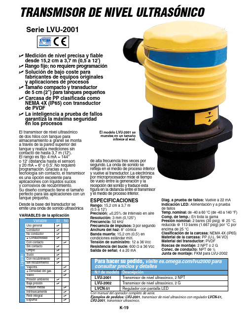
K-19Ejemplos de pedidos: LVU-2001, transmisor de nivel ultrasónico con regulador LVCN-51, LVU-2001, transmisor ultrasónico.EspECifiCaCioNEs Rango: 15,2 cm a 3,7 m (0,5 a 12') precisión: ±0,25% de intervalo en aire Resolución: 3 mm (0,125")frecuencia: 50 kHz frecuencia de impulsos: 3 por segundo anchura del haz: 8° cónica Banda muerta: 15,2 cm (0,5') en condiciones estándar mín.Tensión de suministro: 12 a 36 Vcc Resistencia del bucle: 600 Ω a 36 Vcc salida de señal: 4 a 20 mA U M edición de nivel precisa y fiable desde 15,2 cm a 3,7 m (0,5 a 12')U R ango fijo; no requiere programaciónU s olución de bajo coste para fabricantes de equipos originales y aplicaciones de procesosU T amaño compacto y transductor de 5 cm (2") para tanques pequeñosU C arcasa de pp clasificada como NEMa 4X (ip65) con transductor de pVDfU L a inteligencia a prueba de fallos garantiza la máxima seguridad en los procesosserie LVU-2001Diag. a prueba de fallos: Vuelve a 22 mA indicación LED: Alimentación y a prueba de fallos Temp. nominal: de -40 a 60 °C (de -40 a 140 °F)Comp. de temp.: En toda la gama presión nominal: 2 bares (30 psig) @ 25 °C, reducida @ 113 bares (1.667 psig) por °C por encima de 25 °C Clasificación de la carcasa: NEMA 4X (IP65)Material de la carcasa: PP (U.L. 94 VO)Material del transductor: PVDF Roscas de montaje: 2 NPT o 2 G Conec. de conducto: NPT de 1⁄2 Junta de montaje: FKM para LVU-2002de alta frecuencia tres veces por segundo. La onda de sonido se refleja en el medio de proceso inferior y vuelve al transductor. La electrónica por microprocesador mide el tiempo de vuelo entre la generación y la recepción del sonido y traduce esta figura en la distancia entre el transmisor y el medio de proceso inferior.El transmisor de nivel ultrasónico de dos hilos con tanque para almacenamiento a granel se monta a través de la pared superior del tanque y realiza mediciones sin contacto de hasta 3,7 m (12'). El rango es fijo: 4 mA = 144" o 12' (distancia hasta el sensor) y 20 mA = 6" o 0,5'. No requiere programación. Gracias a su tecnología sin contacto, el transmisor es una opción excelente para aplicaciones con líquidos sucios y corrosivos de recubrimiento. Su diseño compacto tiene el tamaño perfecto para las aplicaciones con un tanque pequeño.Desde la base del transductor se emite una onda de sonido ultrasónicaTransmisor de nivel ulTrasónicoEl modelo LVU-2001 se muestra en un tamaño inferior al real.。
Omega CNi8 1 8 DIN 数字面板表说明书

U High QualityU 5-Year WarrantyU H igh Accuracy: ±0.5°C(±0.9°F), 0.03% Reading U U ser-Friendly,Simple to Configure U Free SoftwareU Full Autotune PID ControlU U niversal Inputs: RTD,Thermocouple, Process Voltage/Current, StrainU T otally ProgrammableColor Displays Standard U B uilt-In ExcitationStandard U 2 Control or AlarmOutputs: DC Pulse, Mechanical Relays, Analog Voltage and CurrentU E mbedded InternetConnectivity Available The OMEGA ®CNi8 is a 1⁄8 DIN size[96 x 48 mm (3.7 x 1.9")] digital panel meter featuring the big iSeries color-changing display. The digits are larger than typical 1⁄8 DIN panel meters. The iSeriesmeters feature LED displays that can be programmed to change color between GREEN, AMBER,and RED at any setpoint oralarm point. The “CNi8” model is available as an extremely accurate programmable digital panel meter with no outputs or with dual outputs for controlling or alarming functions. Other options include isolated programmable analog output, serial communications, and Ethernet. The user can easily program the CNi8 for any control or alarming requirement from simple on/off to full autotune PID with a choice of form C SPDT relays, solid state relays, DC pulse, and analog (voltage and current) outputs.Fully isolated analog output for retransmission of the process value is available in addition to the control and alarm relays (specify model CNi8A33). The CNi8 covers a broad selection of transducer and transmitter inputs with 2 input models.The universal temperature and process instrument (CNi models) handles 10 common types of thermocouples, multiple RTDs, and several process (DC) voltage and current ranges. This model also features built-in excitation, 24 Vdc @ 25 mA. With its wide choice of signal inputs, this model is an excellent choice for measuring or controlling temperature with a thermocouple, RTD, or 4 to 20 mA transmitter.The strain and process instruments (CNiS models) measure inputs from load cells, pressure transducers, and most any strain gage sensor as well as process voltage and current ranges. The CNiS has built-in 5 or 10 Vdc excitation for bridge transducers, 5 Vdc @ 40 mA or 10 Vdc @ 60 mA (any excitation voltage between 5 and 24 Vdc is available by special order). This CNiS model supports 4- and 6-wire bridge configurations, ratiometric and non-ratiometric measurements. The CNiS features fast and easy “in process” calibration/scaling of the signal inputs to any engineering units. This model also features 10-point linearization which allows the user to linearize the signal input from extremely nonlineartransducers of all kinds.1⁄8 DIN Temperature, Process and Strain PID Controllers Shown smaller than actual size.Ordering Examples: CNi8A22, 1⁄8 DIN temperature/processcontroller with isolated analog output and 2 SSR outputs. CNiS833, 1⁄8 DIN strain/process controller with 2-relay outputs.*2 “-DC”, “-C24”, and “-C4EIT” not available with excitation.*3 Analog output is not available with “-AL” units.*4 CNi8A0x-AL contains 1 alarm and 1 analog retransmission.*5 20 to 36 Vdc for CNi8A, CNi8-C4EIT and CNi8-EIT.*6 “-SM” option not available on CNiS strain models.at any setpoint PatentedUniversal Temperature and Process Input (DPi/CNi Models)Accuracy: ±0.5°C temp; 0.03% rdg Resolution: 1°/0.1°; 10 µV process Temperature Stability: RTD: 0.04°C/°C TC @ 25°C (77°F): 0.05°C/°C Cold Junction Compensation Process: 50 ppm/°C NMRR: 60 dB CMRR: 120 dB A/D Conversion: Dual slope Reading Rate: 3 samples/s Digital Filter: Programmable Display: 4-digit 9-segment LED 10.2 mm (0.40"); i32, i16, i16D, i8DV 21 mm (0.83"); i8 10.2 mm (0.40") and 21 mm (0.83"); i8DH RED , GREEN, and AMBER programmable colors for process variable, setpoint and temperature units Input Types: Thermocouple, RTD, analog voltage, analog current Thermocouple Lead Resistance: 100 Ω max Thermocouple Types (ITS 90): J, K, T, E, R, S, B, C, N, L (J DIN)RTD Input (ITS 68): 100/500/1000 Ω Pt sensor, 2-, 3- or 4-wire; 0.00385 or 0.00392 curve Voltage Input: 0 to 100 mV, 0 to 1V, 0 to 10 Vdc Input Impedance: 10 M Ω for 100 mV 1 M Ω for 1 or 10 Vdc Current Input: 0 to 20 mA (5 Ω load)Configuration: Single-ended Polarity: Unipolar Step Response: 0.7 sec for 99.9%Decimal Selection: Temperature: None, 0.1 Process: None, 0.1, 0.01 or 0.001Setpoint Adjustment: -1999 to 9999 counts Span Adjustment: 0.001 to 9999 counts Offset Adjustment: -1999 to 9999Excitation (Not Included with Communication): 24 Vdc @ 25 mA (not available for low-power option)Universal Strain and Process Input (DPiS/CNiS Models)Accuracy: 0.03% reading Resolution: 10/1µV Temperature Stability: 50 ppm/°C NMRR: 60 dB CMRR: 120 dB A/D Conversion: Dual slope Reading Rate: 3 samples/s Digital Filter: Programmable Input Types: Analog voltage and current Voltage Input: 0 to 100 mVdc, -100 mVdc to 1 Vdc, 0 to 10 Vdc Input Impedance: 10 M Ω for 100 mV;1 M Ω for 1V or 10 Vdc Current Input: 0 to 20 mA (5 Ω load)Linearization Points: Up to 10 Configuration: Single-ended Polarity: Unipolar Step Response: 0.7 sec for 99.9%Decimal Selection: None, 0.1, 0.01 or 0.001Setpoint Adjustment: -1999 to 9999 counts Span Adjustment: 0.001 to 9999 counts Offset Adjustment: -1999 to 9999Excitation (Optional In Place Of Communication): 5 Vdc @ 40 mA;10 Vdc @ 60 mA Control Action: Reverse (heat) or direct (cool)Modes: Time and amplitude proportional control; selectable manual or auto PID, proportional, proportional with integral, proportional with derivative and anti-reset Windup, and on/off Rate: 0 to 399.9 s Reset: 0 to 3999 s Cycle Time: 1 to 199 s; set to 0 for on/off Gain: 0.5 to 100% of span; setpoints 1 or 2Damping: 0000 to 0008Soak: 00.00 to 99.59 (HH:MM), or OFF Ramp to Setpoint: 00.00 to 99.59 (HH:MM), or OFF Auto Tune: Operator initiated from front panel Control Output 1 and 2Relay: 250 Vac or 30 Vdc @ 3 A (resistive load); configurable for on/off, PID and ramp and soak Output 1: SPDT, can be configured as alarm 1 output Output 2: SPDT, can be configured as alarm 2 output SSR: ******************.5A (resistive load); continuous DC Pulse: Non-isolated; 10 Vdc @ 20 mA Analog Output (Output 1 Only):Non-isolated, proportional 0 to 10 Vdc or 0 to 20 mA; 500 Ω max Output 3 Retransmission: Isolated Analog Voltage and Current Current: 10 V max @ 20 mA output Voltage: 20 mA max for 0 to 10 V output Network and Communications Ethernet: Standards compliance IEEE 802.3 10 Base-T Supported Protocols: TCP/IP, ARP, HTTPGET RS232/RS422/RS485: Selectable frommenu; both ASCII and MODBUS protocol selectable from menu; programmable 300 to 19.2 Kb; complete programmable setup capability; program to transmit current display, alarm status, min/max, actual measured input value and status Common Specifications (Alli/8, i/16, i/32 DIN)RS485: Addressable from 0 to 199Connection: Screw terminals Alarm 1 and 2 (Programmable)Type: Same as output 1 and 2Operation: High/low, above/below,band, latch/unlatch, normally open/normally closed and process/deviation; front panel configurations Analog Output (Programmable):Non-isolated, retransmission 0 to 10 Vdcor 0 to 20 mA, 500 Ω max (output 1 only); accuracy is ± 1% of FS when following conditions are satisfied: input is not scaled below 1% of input FS, analog output is not scaled below 3% of output FS General Power: 90 to 240 Vac ±10%, 50 to 400 Hz *, 110 to 300 Vdc, equivalent voltage Low Voltage Power Option: 24 Vac **, 12 to 36 Vdc for DPi/CNi/DPiS/CNiS; 20 to 36 Vdc for dual display, ethernet and isolated analog output from qualified safety approved source Isolation Power to Input/Output: 2300 Vac per 1 minute test For Low Voltage Power Option: 1500 Vac per 1 minute test Power to Relay/SSR Output: 2300 Vac per 1 minute test Relay/SSR to Relay/SSR Output:2300 Vac per 1 minute test RS232/485 to Input/Output:500 Vac per 1 minute test Environmental Conditions: All Models: 0 to 55°C (32 to 131°F) 90% RH non-condensing Dual Display Models: 0 to 50°C (32 to 122°F), 90% RH non-condensing (for UL only) Protection: D Pi/CNi/DPiS/CNiS32,16,16D, 8C: NEMA 4X/Type 4 (IP65) front bezel DPi/CNi/DPiS/CNiS8, 8DH, 8DV: NEMA 1/Type 1 front bezel Approvals: UL, C-UL, CE per 2014/35/EU, FM (temperature units only)Dimensions i /8 Series: 48 H x 96 W x 127 mm D (1.89 x 3.78 x 5") i/16 Series: 48 H x 48 W x 127 mm D (1.89 x 1.89 x 5") i/32 Series: 25.4 H x 48 W x 127 mm D(1.0 x 1.89 x 5")Panel Cutouti /8 Series: 45 H x 92 mm W (1.772 x 3.622"), 1⁄8 DIN i/16 Series: 45 mm (1.772") square,1⁄16 DINi/32 Series: 22.5 H x 45 mm W (0.886 x 1.772"), 1⁄32 DIN Weighti /8 Series: 295 g (0.65 lb) i/16 Series: 159 g (0.35 lb) i/32 Series: 127 g (0.28 lb)* No CE compliance above 60 Hz. ** Units can be powered safely with 24 Vac。
- 1、下载文档前请自行甄别文档内容的完整性,平台不提供额外的编辑、内容补充、找答案等附加服务。
- 2、"仅部分预览"的文档,不可在线预览部分如存在完整性等问题,可反馈申请退款(可完整预览的文档不适用该条件!)。
- 3、如文档侵犯您的权益,请联系客服反馈,我们会尽快为您处理(人工客服工作时间:9:00-18:30)。
如何确定我购买的是正宗欧米茄腕表遵循如下步骤可以确定您购买的是正宗欧米茄腕表:- 只在欧米茄指定经销商处购买欧米茄腕表。
- 申请一张信用卡大小的保修卡,完整填写8位系列编号、手表编号以及经销商的完整姓名和地址。
- 如果您想确定腕表是否正宗,请携同欧米茄腕表及保修卡到指定的维修中心,让我们的维修服务员确定您购买的是否为正宗欧米茄腕表。
客户服务网络返回页首计时表(CHRONOGRAPH)与瑞士官方天文台认证腕表(CHRONOMETER)有何区别计时表(CHRONOGRAPH)带有显示时、分和秒的指针,它们与机械系统一起透过中央计时指针测定逝去时间,可以记录到秒,并且具有30分钟和12小时定时装置。
瑞士官方天文台认证腕表(CHRONOMETER)是以不同角度,成功通过温度、精确度和防水功能测试后,获得COSC(瑞士官方天文台)正式颁发的等级证书的腕表。
通过这些测试至少需要15天时间。
返回页首计时腕表上的按钮具有什么功能位于2点钟位置的按钮可以启动或停止计时功能,位于4点钟位置的按钮用于重新计时。
返回页首海马系列专业计时腕表的排氦气阀门具有什么功能排氦气阀门由欧米茄为职业潜水员专门研发。
在深海潜水过程中,潜水员往往会在潜水钟内进行数天作业。
在到达水平面之前,潜水钟内充满氦气和氧气的混合气体。
氦气分子轻于空气,可以渗入手表,并在大气压力的作用下将水晶镜面推出。
在到达水平面之前打开氦气排放阀可以将氦气排放,从而防止手表进水。
返回页首自动上链机芯与手动上链机芯有何区别自动上链机芯与手动上链机芯的区别在于上链方式的不同。
手动上链腕表需要每天人工上链,而自动上链腕表则具有内部摩打,利用手腕的运动来自动上链。
自动上链腕表通常具有至少40小时的动力储存,即使不佩戴手表,仍然能够备有足够的能量储存以保持稳定的运行。
返回页首欧米茄腕表是否具有防振功能是。
欧米茄腕表可以承受重量为5000克的振动。
返回页首欧米茄腕表是否具有防磁性能是。
欧米茄腕表具有防磁性能,符合ISO 764规定的标准。
此标准根据一款腕表任意透过强度为4,800A/M,即特斯拉的磁场测试为基础制订。
ISO 764测试内容包括将手表以3种不同的角度放入磁场内,接受每次长度为1分钟的测试:•沿3点钟至 9点钟方向与手表平面平行的角度•然后沿6点钟至12点钟方向•然后沿与手表平面垂直的角度机械表必须在上述三个角度不停止运行才可通过测试。
残余磁波对男装表款造成的误差每天不可超过30秒,对女装表款造成的误差每天不可超过45秒。
返回页首超霸系列专业计时腕表“月球表”是否配有炭纤维水晶镜面超霸系列专业计时腕表由从事太空活动的航天员佩戴使用。
当美国太空总署(NASA)选择此款腕表时,要求采用炭纤维水晶镜面,因为此种镜面在压力下“不会像蓝宝石水晶镜面那样裂为细小的碎片”。
这一特性对航天员而言十分重要,因为蓝宝石水晶镜面的碎片在完全失重的环境下会带来危险。
返回页首超霸系列中的哪款腕表为首款月球表首款月球表是编号为3570‧50‧00的超霸系列专业计时腕表。
此款腕表采用精钢表壳和表链,配有黑色表盘和炭纤维水晶胶镜面。
防水深度30 米,配有1861手动上链机械机芯。
返回页首哪一只海马表是邦德手表海马专业300米潜水手表曾于五套邦德电影中由邦德佩戴。
这批海马表的表壳和表链均由全钢制造,配以蓝色表盘,单向旋转表圈连蓝色圆环及蓝宝石水晶表面。
手表直径41毫米,防水深度300米。
在电影《007:大战皇家赌场》中,占士邦在获得"00" 身份(“杀人执照”)之后,就开始佩戴直径毫米的海马海洋宇宙表。
在《007大破量子危机》,邦德佩戴的海马海洋宇宙600米表具有欧米茄革命性的同轴系统,以及600米(2000尺)防水功能。
手表直径42毫米,黑色表盘。
1995 黄金眼海马300米潜水表(编号,售罄)1997 不死明天海马300米潜水表(编号,售罄)1999 黑日危机海马300米潜水表(编号,售罄)2002 择日再死海马00米潜水表(编号,售罄)2006 007大战皇家赌场海马300米潜水表(编号)海马海洋宇宙手表(编号)2008 007大破量子危机海马海洋宇宙600米同轴手表(编号)返回页首欧米茄金表采用纯金物质还是镀金物质制造所有欧米茄金表不是在金属表面进行镀金制造,而完全是由实心的18K金(包括18K红金、18K白金和18K黄金)制造而成。
返回页首欧米茄腕表是否通过网络出售欧米茄腕表只在我们指定的经销商处销售。
进行网络销售的公司并非欧米茄的指定经销商。
返回页首对镍过敏的人士是否可以佩戴欧米茄精钢腕表为避免这一问题,欧米茄选用的所有物质均经过多项严格测试。
欧米茄采用的精钢材料不含镍,此元素会透过金属与皮肤接触造成过敏反应。
我们采用的精钢品质极其稳定,因而不会释放镍元素,对于金属过敏人士十分安全。
除非是那些对精钢特别敏感的人士,例如无法使用精钢炊具和餐具的人士。
在这种情况下,我们建议您选购由钛金属制造的手表。
返回页首如何使用超霸系列腕表中的测速计测速计是用于测定速度的仪器。
透过这一计时工具的刻度表盘,可以在1000米距离内以公里读取时速。
如何读取测速计:只需使用中央计时秒针。
对于时间较长的速度读取,应参考计时器(分钟和小时)显示。
以计算汽车的速度为例:计时器显示行驶1公里的时间为30秒。
测速计刻度上的相应点会指示为120,所以汽车行驶的时速为每小时120公里。
返回页首编号为和的海马系列专业计时腕表之间有何区别海马系列专业计时男装腕表具有两种尺寸可供选择:直径41毫米的标准尺寸和直径36‧25毫米的中型尺寸。
海马系列腕表还备有自动和石英两种机芯。
:标准尺寸,自动上链机芯。
:中型尺寸,自动上链机芯。
:标准尺寸,石英机芯。
:中型尺寸,石英机芯。
返回欧米茄计时腕表的误差为多少页首为获取瑞士官方天文台认证,机械机芯的日变化率必须介于平均每天-4/+6秒之间,即精确度达99‧99%,机械机芯可以达到的最高精确度。
机械机芯的精确度取决于每个佩戴者的习惯,并且可能发生变化。
具有专业资格的欧米茄制表技师可以对手表的误差进行调校,直至达到每天介于-1 到 +6秒之间的欧米茄误差标准。
返回页首为何大多数欧米茄腕表都在凌晨1点半至 2点之间变更日期欧米茄采用这一日期变更系统旨在清晰显示午夜左右进行的日期变更过程,直至午夜11点45分仍可全部显示当天日期,以避免产生混淆。
透过日期显示窗口下方,可以完整读取当天日期,而新的日期将显示在日期显示窗口上方。
然后,新日期向下移动至窗口,前一天的日期将逐渐消失。
日期变更将于凌晨1点30分之前全部完成。
在晚上9点到第二天的凌晨2点期间内,请避免手工快调日历。
返回页首欧米茄腕表的夜光为何如此光亮而持久欧米茄所有腕表的表盘和指针均采用SUPER─LUMINOVA材料。
此材料吸收日光以及所有人造光源来发光。
应将手表置于光照之下,以确保表盘和指针在黑暗中,例如在夜间的发光效果。
发光亮度会渐渐减弱,但只需将手表置于光照之下即可恢复发光效果。
返回页首欧米茄自动上链机械腕表的动力储存为多长时间,如何运作欧米茄自动上链机械腕表的运行取决于佩戴者的手腕运动情况。
在完全上链的状态下,手表的动力储存通常为44小时左右。
因自动上链机械系统直接与佩戴者的手腕活动相关,10 至12个小时的佩戴足以产生至少20个小时的动力储存,保证手表夜间的正常运行。
然而,在长达数天没有佩戴的情况下,手表的动力储存会大大减少,我们建议您进行手工上链,将表冠沿顺时针方向转动大约15圈,以保证手表的正常运行。
返回页首欧米茄腕表防水深度可达多少根据表款的不同,欧米茄腕表的防水深度分别为30, 50, 100, 120, 150, 200, 300 和600 米。
PDF防水深度图表。
返回页首如何保证我的腕表多年保持其出色的品质磁场:避免将您的腕表放置在扬声器或电冰箱上方,因为它们具有强烈的磁场。
游泳:坚持在游泳后用温水清洗您的腕表。
撞击:避免热能或其它撞击。
表冠:仔细旋紧表冠,以防止内部进水。
清洁:使用牙刷和温肥皂水清洗金属表链及所有防水表壳,并用软布擦干。
化学品:避免手表与溶剂、清洁剂、香水和化妆品等直接接触,因为它们会侵蚀表链、表壳和垫圈温度:避免极端温度(高于60摄氏温度或140华氏温度,低于0摄氏温度或32华氏温度)或强烈的温度变化。
返回页首何为定期保养手表同其它高度精密的仪器一样,需要定期保养才能保证完美的运行。
显然我们无法在此解释定期保养的内容,因为这完全取决于手表的款式、气候和佩戴者的保养情况。
根据手表的使用情况,定期保养的期限通常为每隔4 至 5年。
返回页首欧米茄腕表是否真的是为了终生佩戴而设计欧米茄保证自生产日期起20年内负责维修和提供手表零件。
超过这一期限后,欧米茄将尽最大努力解决手表收藏者遇到的问题并负责维修旧款手表。
返回页首欧米茄为何不向用户直接提供零配件出于技术和质量上的原因,我们不向用户直接提供零配件。
欧米茄设有全球服务中心,为顾客提供专业服务,实现欧米茄的高品质标准。
返回页首欧米茄为何不收购古董腕表欧米茄不收购古董腕表或已被佩戴过的腕表。
我们建议有意出售此类腕表的人士联系当地的古董商或拍卖行。
返回如何为我新购的配有官方认证机芯的欧米茄腕表取得瑞士官方天文台(COSC)认证页首只要收到您购买的欧米茄腕表国际保修卡复印件、按要求完整填写日期并附有欧米茄指定经销商印章的文件,我们荣幸地为您提供瑞士官方天文台(COSC)认证证书。
返回页首欧米茄其它机械腕表的误差为多少大部分未经瑞士官方天文台认证的腕表其平均误差介于每天-1/+11秒。
机械机芯的精确度取决于每个佩戴者的习惯,并且可能发生变化。
具有专业资格的欧米茄制表技师可以对手表的误差进行调校,以达到欧米茄误差标准。
返回页首欧米茄石英腕表的误差为多少所有欧米茄石英机芯的生产和协调都要经过著名的欧米茄工序并达到严格的品质标准。
环境温度可能影响石英机芯的精确度,出现每天介于和 +秒之间的误差。
返回页首大多数欧米茄腕表在甚么时候变更日期欧米茄采用慢速及快速日期变更系统:采用慢速日期变更系统的机芯包括1128, 1150-1-2, 1164, 1270, 1379, 1400, 1424, 1426, 1429, 1430, 1432 , 1438 , 1441, 1449, 1479, 1530, 1532, 1538, 1675, 2520, 2600, 2628, 3603 与3606型。
欧米茄采用慢速日期变更系统旨在清晰显示午夜左右进行的日期变更过程,以避免产生混淆。
直至午夜11点30分日历窗仍可全部显示当天日期。
至午夜时,当天日期仍可透过日历窗下方完整读取,而新的日期将出现在日历窗的上方。