ds-k1108am说明书
米勒 DS5 DS10 DS20 流动头操作手册说明书

DS5/DS10/DS20 Fluid Head Operator’s Manual #180 DS5 Fluid Head#182 DS10 Fluid Head#184 DS20 Fluid HeadFeatures and Controls2Fig 1.1DS5Fig 1.2DS101/4” and pin carriageSliding camera plateSlide lockTilt lockTilt dragPan handle clampCounterbalance selectorPan lockPan drag75mm claw ballClamp nutIntroductionThank you for purchasing the Miller DS5/DS10/DS20 fluid head for use with our professional tripods and portable video camcorders. All fluid heads are 75mm ball levelling design and boast similar physical appearance and size. The DS5 utilises a single position counterbalance system to handle camera payloads up to 2.5kg (5.5lb). The DS10 utilises 2 selectable counterbalance positions to handle payloads from 2.5-5kg (5.5-11lb) while the DS20 offers 2 selectable counterbalance positions for larger camcorders ranging from 5-10kg (11-22lb).The DS5/DS10/DS20 fluid head is designed for maximum stability, accuracy and repeatability and includes 4 precision ball bearings and a fluid drag plate system in the pan and tilt assembly to deliver true fluid drag performance over a wide temperature range and payload. The DS10/DS20 fluid head also includes a friction drag adjustment.The DS5/DS10/DS20 fluid head will give best performance when used on Miller SOLO DV (#1630, #1501) or Toggle Lightweight DV (#440, #420) tripod. This will ensure maximum system stability to suit any professional set-up. The DS5/DS10/DS20 fluid head will fit most industry standard 75 mm tripods as well, please refer to manufacturers’ manual for mounting details.Handle MountingThe DS5/DS10/DS20 fluid head is supplied with a fixed length pan handle and clamp fitted to the right side of the head. A second pan handle can be attached to the DS5/DS10/DS20 for dual pan handle operation. Refer to spare parts section.31/4” and pin carriage Sliding camera plate Slide lockTilt drag Pan handle clamp Counterbalance selector Pan lock Pan drag 75mm claw ball Clamp nutCamera screwsFig 1.3 DS20Before using please read the following operating instructions. Do not omit any step. N.B. The safe operation of this piece of professional equipment is the responsibility of the operator.1.1 L oosen the PAN HANDLE CLAMP fully, then rotate thePAN HANDLE until it is approximately perpendicular to theTHREADED STUD and tighten the PAN HANDLE CLAMP- avoid contact wear between the serrations on the FluidHead and the PAN HANDLE CLAMP, if this occurs thenunwind the PAN HANDLE CLAMP further.1.2 E nsure that the TRIPOD BOWL is approximately horizontal.Place the Fluid Head into the TRIPOD BOWL, adjust theBUBBLE LEVEL such that the bubble is inside the blackcircle and tighten the CLAMP NUT.Note: If adjusting the level with your camera mounted, first ensure the camera is securely held before loosening CLAMP NUT.Please note that the best camera control can be achieved by balancing camera centre of gravity (C of G) over centre axisof the head, and by selecting the appropriate counterbalance position to suit the weight of the camcorder payload.The DS5/DS10/DS20 is equipped with a sliding camera plate and a removable 1/4”-pin carriage which is standard mounting for DV and MiniDV camcorders. The DS20 is also fitted with a 3/8” & 1/4” screws which is standard mounting for DVCAM (see Fig1.3). The 3/8” & 1/4” screws also allow the DS20 to attach to a proprietary Quick Release Tripod Adaptor or “tripod base plate” such as the Sony VCT-14 or Panasonic SHAN-TM700.2.1 L ock PAN and TILT LOCKS (rotate both levers clockwise untilfirm).2.2 R emove CAMERA PLATE from CAMERA PLATFORM byunlocking the SLIDE LOCK, pushing SAFETY TAB and sliding the CAMERA PLATE rearward2.3 W ith accessories and battery fitted to the camera, it isrecommended to estimate the camera’s Centre of Gravity (C of G) for the purpose of correctly positioning the camera on the CAMERA PLATE. The camera’s C of G can be estimated by placing the camera on to a round rod and then shiftingit backwards or forwards until a balance point – C of G - is achieved. It is recommended to identify this point as it will be useful in step 2.5.2.4 R efer to the Camera’s owners manual for correct method ofattachment to the CAMERA PLATE. Attach the camera or the Quick Release Tripod Adaptor to the CAMERA PLATE andsecurely tighten the screws.2.5 C heck that the SLIDE LOCK is loose, then align theCAMERA PLATE with the CAMERA PLATFORM andslide it forward until the safety mechanism is engaged.Then, slide the CAMERA PLATE so that the camera’s C of G is directly above the centre axis of the Fluid Head and tighten the SLIDE LOCK. If this can not be achieved then reposition the camera or the Quick Release Tripod Adaptor on theSLIDING PLATE – step 2.4. This will ensure that the system has maximum stability.2. Camera Set-up1. F luid Head Set-up4The counterbalance system was designed to neutralise the effect of the camera weight when it is tilted. The DS10 & DS20 Fluid Head offers a 2 position counterbalance system which can be operated via the COUNTERBALANCE SELECTOR (Fig. 2 & 3). The DS5 Fluid Head has a single position Counterbalance system and is preset. The COUNTERBALANCE SELECTOR must be operated when the SLIDING PLATFORM is in a horizontal position. After changing the Counterbalance setting it may be necessary totilt the camera back and forth to ensure that the CB spring has engaged. The camera must be held securely while changing the Counterbalance setting.3.1 F or safety ensure that Counterbalance position 2 is selected.3.2 H old the camera and release the TILT LOCK, then gently tiltthe camera from a horizontal position forward then backward and observe its response. If the Camera 'Springs Back' to the horizontal position then selectCounterbalance position1. Correct Counterbalancesetting has been achievedwhen minimum effort isrequired to move the cameraover the entire tilt range.TIP F ine tuning can be achievedby adjusting the SLIDINGPLATFORM - see step 2.5.The DS5/DS10/DS20 Fluid Head offers highcapacity calliper disc brake system to holdthe Fluid Head in a fixed pan and/or tilt position.Camera position will not change when applying orreleasing the Pan / Tilt locks.WARNING: Do not pan or tilt the Fluid Head whilst the PAN orthe TILT LOCK is partially applied.5Fig 2DS10 CB Selector Fig 3 DS20 CBSelector3. C ounterbalanceControl 4. P an / Tilt LockControl65.1 The DS10/DS20 fluid head provides adjustment for tilt and pan drag control (Fig 4.). Rotate clockwise to engage friction resistance, anticlockwise to return to fluid action.Note: The fluid drag plate system has been designed to suit most operating conditions. The friction drag adjustment should only be utilised when extra resistance is required.The DS5/DS10/DS20 fluid head features protective coatings, dust seals and anti-corrosive fittings to ensure long and trouble-free operation in extreme location conditions. To ensure optimum performance throughout the life of the head Miller recommends regular cleaning.When the fluid head has been used in harsh environments (such as sand, mud or salt water spray), wipe over with a soft damp cloth as soon as possible. Use a soft brush to clean crevices. Remove and clean CAMERA PLATE.WARNING: Do not immerse a fluid head in any liquid.WARNING: Do not use stiff brushes, abrasives or solvents.StorageWhen storing for extended periods: clean fluid head and place in a safe, dry place, away from direct sunlight. The fluid heads can be stored horizontally or upright. However, it is not advisable to leave the head for extended periods with the tilt locked in an extreme position, either forward or backward.MaintenanceWith the exception of cleaning, the DS5/DS10/DS20 fluid head does not require additional maintenance. Miller recommends periodic servicing by a Miller Authorised Service Agent. Miller Authorised Service Agents must carry out all service and repair work. Failure to observe this requirement may void warranty.CleaningFig 4Drag control knobsOperating Instructions 5.P an / Tilt Drag ControlTechnical DataSpecifications – DS5/DS10/DS20 Fluid HeadDescription DS5 (#180) DS10 (#182) DS20( #184)Weight - kg (lb) 1.6 (3.5) 1.7 (3.7) 1.75 (3.9)Payload Range - kg (lb) 0.5 - 2.5 (1.1 - 5.5) 2.5 - 5.0 (5.5 - 11.0) 5.0 - 10.0 (11.1 - 22.0)Pan/Tilt Drag Fluid Drag plate system Fluid Drag plate system Fluid Drag platesystem with friction boost. system with friction boost.Pan/Tilt Lock brake system Calliper Disk Brake Calliper Disk Brake Calliper Disk BrakeTilt Angle Range +90˚/-75˚ +90˚/-75˚ +90˚/-75˚Counterbalance System Single Position Two Position Two PositionPosition # 1 capacity - kg (lb) Up to 2.5 (5.5) Up to 2.5 (5.5) 2.5 - 5.0 (5.5 - 11.0)Position # 2 capacity - kg (lb) - 2.5 - 5.0 (5.5 - 11.0) 5.0 - 10.0 (11.0 - 22.0)Camera Platform Type Quick Release Sliding Camera Quick Release Sliding Camera Quick Release Sliding CameraPlate with 60 mm travel. Plate with 60 mm travel. Plate with 60 mm travel.Camera Plate Standard DS with Standard DS with Standard DS with1/4” + Pin Adapter Carriage 1/4” + Pin Adapter Carriage 1/4” + Pin Adapter Carriage1/4” and 3/8” screwsBubble Level Yes Yes YesMounting Base 75 mm ball levelling 75 mm ball levelling 75 mm ball levellingHandle Standard Pan Handle Standard Pan Handle Standard Pan HandleTemperature Range - ˚C (˚F) -40˚/+65˚ (-40˚ / +149˚) -40˚/+65˚ (-40˚ / +149˚) -40˚/+65˚ (-40˚ / +149˚)7MILLER CAMERA SUPPORT (Australia) 30 Hotham Parade, Artarmon, Sydney NSW 2064 AustraliaTel: +61 2 9439 6377Fax: +61 2 9438 2819Email:****************.auMILLER FLUID HEADS (Europe) LTD. Unit 12A, Shepperton Business Park Govett Avenue, Shepperton, Middlesex TW17 8BA United KingdomTel: +44 (0) 1932 222 888Fax: +44 (0) 1932 222 211Email:******************************MILLER CAMERA SUPPORT LLC (USA) 218 Little Falls Road, Cedar Grove New Jersey 07009-1231 USATel: (973) 857 8300Fax: (973) 857 8188Email:**********************D3573 - 2 03/10ITEM ITEM NO. DS5/DS10 Camera Plate (inc. #493 carriage) #490 DS20 Camera Plate (inc. #493, 3/8” & 1/4” screws) #489 1/4”– Pin carriage #493 Camera Screw 1/4” P0036 Camera Screw 3/8” P0037 Fixed Length Pan Handle #688 Fixed Length Pan Handle & clamp #680 Pan Handle Clamp P3436 Clamp Nut P2321WarrantyMiller offers a comprehensive parts and labour warranty with all it’s camera support products. For complete details please refer to the warranty card enclosed or contact your nearest Miller sales or service centre.Website For information about the complete range of Miller camera support products, or to find the address of your nearest authorised Miller sales centre, please visit our website at .Service, Sales & SupportMiller Authorised Service Agents must carry out all service and repair work. Failure to observe this requirement may void warranty. It is advisable to notify Miller or a Miller Authorised Service Agent if a change of performance is observed as a result of dropping or rough usage. For your nearest authorised Miller sales or service centre, please visit our website at .Spare Parts。
AMK伺服系统使用说明书

AMK伺服系统使用说明书目录系统简介————————————————1 电源模块————————————————9 驱动模块————————————————15 控制面板————————————————24 参数配置————————————————30 故障诊断————————————————46 附录:参数列表一、系统简介1.伺服电机AMK伺服电动机分DH、DS、DT、DV和DW等系列,其编码器分为旋转变压器型编码器(R)、HiperFace接口型编码器(S/T)、EnData接口型编码器(E/F)和增量型编码器(I)。
其中,旋转变压器型编码器通过DB9型插头连接到KW驱动器的X130接口;其他型号的编码器通过DB15型插头连接到KW驱动器的X131接口。
AMK伺服电动机编码器接口引脚功能表KW驱动器编码器接口引脚功能表AMK伺服电机的动力接线也采用航空插头的接线方式,其根据电机功率大小采用的插头大小不同,但其动力电缆的引脚分布基本相同。
AMK电机动力接口引脚功能表引脚功能引脚功能PE A 热敏电阻1 U B 热敏电阻4 V C 抱闸3 W D 抱闸AMK伺服电机型号定义1)DW液体冷却主轴电机DW系列液体冷却三相异步电机在高功率时也有紧凑的结构,恒功率调速范围为1:3,额定功率可高达28kW,额定力矩可高达150N.m,重载型设计和加强型轴承允许高径向载荷。
DW伺服电机型号定义及名牌数据2)DS系列同步伺服电机DS系列同步伺服电机具有结构紧凑,高动态响应,调速范围宽等特点。
这些无刷的永磁交流伺服电机,是4极的或6极的。
DS系列伺服电机型号定义及名牌数据3)DV系列伺服电机DV系列伺服电机是坚固的感应式异步交流电机,不会消磁,具有较高的过载能力和平稳的运行特性。
DV伺服电机在从0加速到额定速度的过程中提供的几乎是恒定转矩,最高转速可扩展至10000r/min,力矩范围为0.3------26N.m。
達科通 Dahua O5K1 O8K1A 8MP IP全機械視頻鏡頭及 NVR 系統使用說明说明书

•Supports up to 5MP resolution (O5K1)•Supports up to 8MP resolution (O8K1A)•2.8mm wide angle lens•True Day/Night operation (IR cut filter)•IR range up to 100ft (built-in IR LEDs)•Supports H.265/H.264 compression •IP66 compliant, weather resistant•Includes Micro SD card slot up to 128GB •Built in mic (O8K1A)•NVR with 2TB hard drive •Five 5MP cameras•One 8MP Advanced Analytic camera •Six 60ft Ethernet cables •One 3ft Ethernet cable •Remote control •2 x AAA Batteries •HDMI cable• Up to 8MP resolution for live view, recording, and playback• Plug & Play – get video automatically via the PoE ports without any setup • Facial Recognition and Comparison*• Human and Vehicle Detection*• Supports H.265 and H.264 streams• QR code based network setup for easy remote access • Free US-based DDNS service• 4K monitor output • Gigabit Ethernet port• Built-in S.M.A.R.T technology (Self-Monitoring, Analysis and Reporting Technology for HDD)• Remote monitoring via PC and mobile apps • 2TB storage• Expansion available for up to 8 cameras totalFront panelRear panelCamera FeaturesRecorder FeaturesHard drives excluded. iPhone is a trademark of Apple Inc., registered in the U.S. and other countries. Android is a trademark of Google Inc. The terms HDMI and HDMI High-Definition Multimedia Interface, and the HDMI Logo are trademarks or registered trademarks of HDMI Licensing LLC in the United States and other countries. ZIPK8TA8 Channel Network Video Recorder with Built-In PoE 5 5MP IP Cameras1 8MP Advanced Analytics IP CameraWhat’s in the Box:O5KJBDCamera Junction BoxO5KWMT EZ Wizard : for easy network and system setup EZ Search: search events from thumbnails EZ Record: set up recording resolutions and recording typeEZ Copy: copy what you are playing onto a USB flash driveEZ App Setup: just scan a QR code with the app to view your cameras on your mobile deviceKey FeaturesH.265IP66*use with O8K1A。
ds-1108打码机说明书

万特ds-1108墨轮打码机说明书产品参数:编号:524546品牌:万特型号:DS-1108墨轮打码机上市时间:2019-04-01打码机的操作和使用:1.接通打码机,开关电源,打开手动打码机总开关,使其工作。
2.打码机的开关电源接通后,不能立即开始编码。
设备应该加热几分钟。
3.将温度调节到合适的部位。
一般两到三度的温度比较合适,但不同的复印原料对温度要求不同,需要根据实际情况调整温度。
4.把打码机放在打码位置上,尽量选择光纤强的地方。
后来实际操作对光源有一些规定,再小心翼翼的从塑料盖前面打开。
幅度要适中,不然坏了就麻烦了。
5.打开打码机的盖子后,取出购买的标签纸,剥去标签纸外面的塑料保护膜,取出一卷,按取出的顺序撕下标签纸,贴牢。
将标签纸放在定价机内侧的正下方,即标签纸突出的一面在定价机外侧。
6.把打码机倒过来。
打码机两侧各有一个按键电源开关。
用拇指和无名指按下,打开开关门,然后打开定价机后盖。
打开后盖后,正下方有一个灰黑色的拉环,可以拉起来。
7.打开后盖后,转回打码机,拉出标签纸,指向向下标记的区域,然后插入标签纸。
8.后盖必须保持不变。
标签纸出纸区有一个小轮子,标签纸通过轮子之间的缝隙。
打码机纸装载方法:1.首先根据图纸上的方向将价格纸固定在轴上。
2.打开后盖,不要暴力破解。
3.在后盖内部还有一个罩子罩住定位轮。
按下盖子。
4.平稳地放入纸张,然后从另一端的定位轮中拉出,长度约10CM。
5.在第3步中弄平纸张并盖上盖子。
6.在定位轮的小凸耳上的价格纸上打一个小孔。
最后盖上后盖,完成。
迷你音响的使用说明书与注意事项
迷你音响的使用说明书与注意事项有关迷你音响的使用说明书与注意事项无线蓝牙音箱使用说明书感谢您选用领秀科技生产的dgshow迷你音箱,为了让您轻松体验产品,我们配备了内容详尽的使用说明,您从中可以获得有关产品的介绍,使用方法等方面的知识,在您使用本机前请先仔细阅读说明书,如果有印刷错误或翻译失误望广大用户谅解。
此款迷你音箱共有两个版本:蓝牙版(型号DG-MS008-B)、普通版(型号DG-MS008-T);只有蓝牙版(型号DG-MS008-B)才能实现蓝牙相关的功能,请您核对购买的产品型号以及产品底部标签上:加图。
一、注意事项为了使用者正确使用播放器,确保播放器性能良好,请认真阅读并遵守:切勿严重撞击主机。
切勿接触苯、稀释剂等化学药品。
请不要靠近强磁场、电场。
请避开直射光线或发热器具。
切勿自行拆卸、修理、改造。
骑车、驾驶汽车及摩托车时,请勿使用播放器及耳机,以免造成危险。
切勿以较大音量收听,以免对听力造成不良影响。
废弃包装、电池、旧电子产品,请分类妥善处理。
二、功能特点[蓝牙音频] Bluetooth 3.0+EDR,最大接收距离10米。
[蓝牙通话] 语音清晰、无回声。
[MP3 播放] 直接播放TF卡内存放的MP3文件。
[FM收音机] FM数字立体声收音机,电台记忆播放。
[音频输入] 立体声音频输入接口,轻松连接电脑、数码音乐播放器、手机等音源设备。
[断点记忆] 自动记忆上次退出时的曲目,音量大小。
[内置电池] 内置可充电锂电池,环保,节能,实用。
[USB读卡器] 连接电脑,可拷贝或删除TF卡中的`歌曲。
[USB声卡] 连接电脑,播放电脑音频文件,可控制电脑上下曲、音量大小。
三、播放音乐操作本机开机时自动检测识别外接设备,开机后进入蓝牙/FM 模式,插入TF卡自动识别播放,后者优先原则,也可自行切换播放模式;插入音频信号线不自动切换,通过[O/PLAY]键切换到AUX模式下播放,详细功能操作请阅读第四项“产品的按键、插孔功能定义”。
ds-k1t85m说明书

ds-k1t85m说明书DS-K1T8115M说明书一、产品概述DS-K1T8115M是一款高性能的人脸识别终端设备,采用深度学习算法,可进行高精准度的人脸识别,并配备了多种输入和输出接口,适用于各种门禁场景。
二、产品特点1.高精准度:采用深度学习算法,具备较高的人脸识别准确率和识别速度。
3.多种接口:配备了多个输入和输出接口,可与其他设备快速连接。
4.多种工作模式:支持离线模式和在线模式,可根据需要进行配置。
5.安全可靠:支持防破坏报警、防撬报警等安全功能,确保门禁系统的安全性。
三、产品参数1. 外观尺寸:160mm × 122mm × 33mm2.重量:约500g3.屏幕尺寸:7英寸4.屏幕分辨率:1024×6005.存储容量:4GB8.工作模式:离线模式、在线模式9.识别准确率:高于99%10. 通信接口:TCP/IP、RS485、Wiegand输入/输出11.电源输入:DC12V12.功耗:≤10W13.防护等级:IP65四、安装与配置1.安装:将设备固定在门禁控制器附近的合适位置,保证设备能够正常工作。
2.连接:将设备与门禁控制器连接,根据接口类型选择相应的连接方式。
3.配置:通过设备菜单进行相应的配置,包括网络设置、识别方式设置等。
五、使用方法1.人脸识别:用户站在设备前,设备自动识别人脸并进行比对,识别成功后开门。
六、注意事项1.请确保设备安装牢固,避免摇晃或移动。
2.请保证设备正常通电,并根据实际需要配置正确的电源。
3.请保持设备屏幕清洁,避免影响识别效果。
4.请勿尝试私自拆卸设备,以免损坏设备或导致不可修复的故障。
5.请定期检查设备的安全性能,确保系统的正常运行。
七、常见问题解答1.设备无法识别人脸:请确保人脸正对设备,避免遮挡或光线过暗。
3.设备开门后立即关闭:请检查设备与门禁控制器的连接是否正常。
4.设备无法联网:请检查设备的网络设置是否正确,确保网络连接正常。
欧米达温度记录仪产品说明书
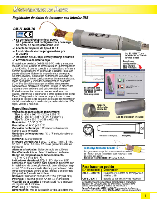
R EGISTRADORES DED ATOSU S e conecta directamente al puerto USB para una fácil configuración y descarga de datos, no se requiere cable USB U A cepta termopares de tipo J, K o T U 2 umbrales de alarma programables por el usuarioU I ndicación de LED rojo, verde y naranja brillantes U A dvertencia de batería bajaEl registrador de datos OM-EL-USB-TC mide y almacena más de 32.000 lecturas de temperatura de un termopar tipo J, tipo K o tipo T que se conecta a un receptáculo miniatura hembra para termopar en la base de la unidad. El usuario puede establecer fácilmente los parámetros de registro de datos iniciales, incluido tipo de termopar, velocidad de registro, hora de inicio, configuraciones de alarma alta/baja, modo de registro y unidades de temperatura deseadas(°C o °F) y también descargar los datos almacenados conectando el módulo en el puerto USB de un ordenador y ejecutando el software para Windows fácil de usar.Posteriormente, los datos se pueden mostrar en un gráfico, imprimirse y exportarse a otras aplicaciones como Excel. El registrador de datos se proporciona con una batería de litio de larga duración. El estado del registrador de datos se indica por medio del parpadeo de luces LED rojas, verdes y naranjas. Especificaciones Variación de medición de temperatura:T ipo J: -130 a 900 °C (-202 a 1.652 °F) Tipo K: -200 a 1.300 °C (-328 a 2.372 °F) Tipo T: -200 a 350 °C (-328 a 662 °F)Resolución: 0,5 °C (1 °F)Precisión: ±1,0 °C (±2,0 °F)Conexión del termopar: Conector subminiatura h embra para termopar Unidades de temperatura: °C o °F seleccionable en software Memoria: 32.000 lecturas Intervalo de registro: 1 seg., 10 seg., 1 min., 5 min., 30 min., 1 hora, 6 horas, 12 horas (seleccionable en software)Alarmas altas/bajas: Seleccionable en software Hora/fecha de inicio: Seleccionable en software Rango de temperatura de funcionamiento: -10 a 40 °C (-14 a 104 °F)Indicadores visuales (LED): 2 LED: el primer LED parpadea en color naranja para indicar un problema con el registrador de datos, por ejemplo batería baja; el seg-undo LED indica estado de alarma y parpadea en color verde (temperatura dentro de los límites) o en color rojo (temperatura fuera de los límites).Software: Windows ® 2000/XP/VIST A/7 (32 y 64 bits)Potencia: 1⁄2 batería de litio AA de 3,6 V (incluido)Vida útil de la batería: 6 meses (a 25 °C e intervalo de registro de 1 minuto)Peso: 43 g (1,5 onzas)Dimensiones: Vea la ilustración arriba, a la derecha Registrador de datos de termopar con interfaz USB configuración del software para Windows Soporte de bolsillo (incluido)Tapa de protección (incluido)operador en CD-ROM, tapa de protección, sujetador para bolsillo, termopar tipo K y batería de litio de 3,6 V .Ejemplo de pedido: OM-EL-USB-TC, registrador de datos de termopar con interfaz USB y OM-EL-BATT , batería de reemplazo.Incluye un termopar tipo K de alambre rebordeado aislado de 1 m (40") gratuito con conector subminiatura y soporte de carrete para alambre. Solicite un recambio Modelo Nº SC-GG-K-30-36.Se incluye termopar GRATUITO。
Grindmaster 咖啡豆液机说明书

Line up arm holes so they line up to the holes on the bottom of the unit; arms1. Roll chassis up-side down2. Open bottom flaps. Fold back.3. Hold flaps out of way. Roll the carton over.4. Lift off carton. Remove bottom pad.BOTTOM PAD CHASSIS Figure A Figure DSPRAY TUBE3/8” TABBOWLGUIDE PINCHASSIS F R O N TCOOLING PLATE BEARING SLEEVE IMPELLER BOWLGASKETPUMPCOVERLOCKDOWN WASHERPage 26” (15 cm)Page 3Crathco® Beverage Dispensers Place the pump cover over the guide pin with the spray tube toward the front.Note that the tab on the front of the pump cover fits between the 2 locator buttons on the bowl. Mini units - bent part of spray place of pump cover and spray tube forfresh juice, drinks that foam (iced tea ordairy products), or heavy viscous drinks.LOCKDOWN WASHER OR CLAMPS• Place lockdown washer over guide pin.in a lockdown pin and snap (Lock down 2 clamps closest to ON BOWL Turn bowl upside down and placebowl gasket over the neck of thebowl. Moisten gasket with water.On D112 units place bowlPlace the neck of the bowl over center of the coolingPlace handle (C) in the two From inside bowl, lower the through the outlet hole, and through the hole Lower pan cover into the top ofthe drip pan. Place top edge of drippan up under lip on front panel.Lower each drip pan so that the tab goes down into the tab slotRegular units proceed to step 15.1. HOLD HANDLE IN “V” NOTCHES &LIFT REAR OF HANDLE UP .2. FROM INSIDE THE BOWL, LOWER THE VALVE THROUGH OUTLET HOLE, AND THROUGH HOLE IN THE HANDLE.3. RELEASE HANDLEHANDLE O-RINGVALVE LOCKDOWN WASHER LOCKING KEYWAY 3/8”TAB “FRONT” OF DISPENSER(TOWARD VALVE ATFRONT OF BOWL)HEAD OF GUIDE PIN CROSS RIBS PUMP COVER BASEPLATE TAB SLOTS FRONT PANEL LIPHANDLE INTO “V” NOTCHES AND PLACE VALVE INTO HOLE.TURN VALVE 90° TO LOCK.Cross slot (located on top ofvalve) should run left to rightacross the bowl whenlocked. PUSH WHIPPER BLADE INTO PLACE.Replace the whipper blade bylining up the flat inside the bladewith the flat side of the motor shaft. Pushpositioning the medium-sizedopening up and tilting 1/8 turnto the right. Put whipperchamber over whipper bladeand turn to the left until it locksHANDLE SHOULDERS GOINTO “V’NOTCHES RINGSLEEVEDOWNVALVE HOLESPRINGVALVE HOLE SPRING “W”ISWHIPPERVALVE TOP (LOOKING DOWN INTO BOWLS)CROSS-SLOTVALVE DOWN IN HOLEREADY TO LOCK AFTER 90°TURN,VALVE IS LOCKEDO/OFFRing sleeve on bottom of handle Rubber inlet adapter Plastic whipper housing13BOWLS WITH PRODUCT and replace lids on bowls.Turn spray switch on first then refrigeration.SPRING HOLE Crathco® Beverage Dispensers Page 4• DISASSEMBLE THE RUBBER INLETRemove one end from the large tubular inletREMOVE LOCKDOWN WASHER(S)Release each clamp.A BEVERAGE FROM BOWLSB 4Ring sleeve on bottom of handle Rubber inlet adapter Plastic whipperhousing VALVE HOLE SPRINGVALVE HANDLEPage 5Crathco® Beverage Dispensers1)Wash all bowl components regularly.2) Wash impeller and bearing sleeve individually and check forwear.a) Check for wear on bearing sleeve (flange should be1.77mm thick - thickness of penny or quarter). (Figure B)b) Check for wear on impeller (inner white center sectionshould be flush with colored part of impeller). (Figure A)c) If bearing sleeve or impeller do not spin freely or are worn- replace them. (Figure E)d) Worn parts can cause personal injury, impair cooling andcan damage machine. (Figure C & D)3) Check valve o-rings and bowl gaskets for wear or damage -replace every 6 months or as needed.4) Every 6 months or more often if needed: unplug unit, removepanels, clean condenser and interior. (Remove dust and lintfrom fins with a soft brush and vacuum.)5) For further information, visit orcall (800) 695-4500.Figure AFigure B Figure C Figure D Figure E Universal Impeller (Part #3587)Page 7Crathco® Beverage DispensersBottom ofWorn ImpellerReplace when worn.Yellow or white area nolonger flush but indented.Top of Impeller Bottom of Unused Impeller Yellow or white area should beflush with colored area.SECOND SECTION*FROM THE FRONT -TOP ROW FRONT ROW - TOP S T A N D A R D - 4’S F R O N T S T A N D A R D - 3’S F R O N T Figure 1Figure 2PADLOCK HERESECURITY KIT INSTALLATION - MINI MODELSPadlock 5/16 Screw Security Clamp Front of Unit Cap Nut Back of Unit Top Tray Lockdown Channel Security Upright Security Bracket Screw 10-24 x 3/4Drip Lip The valve security kit locks dispense valve to prevent use when store is closed. The bowl security kit locks the lid on the bowl to prevent unauthorized access.Valve Handle Step 1Step 2Step 3Mini Model Valve Locking Device Exploded View Page 9Crathco® Beverage Dispensers(Model D35 shown here)Figure QECFABDFCondensate Tray Evaporator TubingThermostat WellThe impeller must spin freely when the bearing sleeve is held betweenance between the magnet and the underside of the top tray. The spacers on the motor bracket may be removed first1. Remove the pump motor assembly from the unit by loosening the (2) pump motor bolts with a 7/16 wrench. (To remove the left pump motor assembly on a D25, you will have to remove the (2) bolts that connect the frame to the top tray on the left side and raise the frame slightly to slide the motor out.)Figure N THIS IS A TRIAL AND ERROR ADJUSTMENTBEARING SLEEVE IMPELLERSTAINLESS TOP TRAY3/32” ALLEN SETSCREWGUIDE PIN PUMPMOTOR NUTREFRIGERATION TEST2. Turn unit ON minutes.Trouble Shooting GuideIf you still need help, call an authorized dealer in your area or Grindmaser Corporation’s Technical Service Department. You can reach Technical Service at (800) 425-4776 Monday-Friday, 8:00 AM-6:00 PM Eastern Standard Time. Please have the model and serial number ready so that accurate information can be given.Prior authorization must be obtained from Grindmaster Corporation’s Technical Service Department for all warranty claims.Exploded ViewStandard andWhipper Models (D15, D25, D35, &WD)Parts ListStandard and Whipper ModelsStandard Whipper ComponentsExploded View Mini Models (E27/9 or E47/9)Parts ListMini Models (E27/9 or E47/9)Exploded View and Parts List HD15 - Heated Models116211651257322510102243202310121150117522662484 (not shown)230522312232Part #Description Models Used On Super Bowl (D112) Bowl Assembly Parts3587Crathco® Beverage Dispensers Page 20Wiring Diagramfor Heated Models (HD15 &WHD15)115V/60Hz and 230V/50HzCrathco® Beverage Dispensers Page 24。
- 1、下载文档前请自行甄别文档内容的完整性,平台不提供额外的编辑、内容补充、找答案等附加服务。
- 2、"仅部分预览"的文档,不可在线预览部分如存在完整性等问题,可反馈申请退款(可完整预览的文档不适用该条件!)。
- 3、如文档侵犯您的权益,请联系客服反馈,我们会尽快为您处理(人工客服工作时间:9:00-18:30)。
6S40柴油机ME中文说明书
适用于公路,铁路,船舶,载货汽车等非道路用柴油机。
发动机功率:240 kW。
燃料:天然气。
操作方法:发动机:1.工作正常时打开钥匙开关;2.接通电源使机油泵开始运转,在规定时间内无任何故障指示指示灯亮;3.工作正常时打开燃油供给阀使机油进入油箱,当发动机停止运转时关闭燃油供给阀;4.关闭电源使机油泵停止工作,然后拧开油箱盖螺钉把发动机放掉。
如有必要应添加机油和燃油后,按说明书规定加入适量润滑油再起动发动机。
1.按操作说明进行操作,应注意在使用过程中安全。
发动机熄火后,不要再启动,防止出现安全事故。
在非道路上操作时应注意以下事项:a.在工作中注意安全,不可将手伸入油箱内操作。
b.不可向燃油供给阀或燃油泵注入燃油和机油。
c.必须保持燃油压力在规定压力下,以便安全操作,并在油箱外加满油。
d.必须保持燃油的清洁,不得用燃油过滤器堵塞滤清器。
2.检查操作和保养
各操作的人员必须经专业培训合格后方可操作;a.操作前要对发动机各部件进行检查保养,以保证各部件工作正常;b.发动机在使用过程中不允许人随便开关门,应采用锁止装置固定好活塞和活塞环;c.运转中的柴油发动机应按规定加油,发动机工作正常时,应打开柴油供给阀使机油进入油箱,当发动机停止运转时关闭燃油供给阀;d.燃油添加到规定里程时不得少于50 km;e.柴油发动机应使用合格润滑油;机油、油封等应定期检查。
3.停机保养与操作:
停机时应关闭汽缸盖,然后打开机油泵阀门,放空燃油,待机油压力降至0.6 MPa以下,方可拆下燃烧室进气门拉紧螺钉。
如需要拆下发动机进气管拉紧螺钉时,应先把进气管拉紧螺钉使气缸壁与进气管之间形成间隙,然后把缸盖螺钉安装到柴油机上,然后用手扳动螺钉将燃烧室中的气体排出,然后再用手拧开气缸盖螺钉孔拧开机油滤清器滤网;机油滤清器能有效过滤发动机产生的废气中的有害气体时在不需要拆开机械时直接把汽油、柴油喷入燃烧室中即可;但如需关闭机械时应先把柴油吸到气管中以排除其中有害气体,并进行清洗。
待机油温度升高后把汽油排出发动机中气体。
最后卸下缸盖螺钉头放掉机油并用压缩空气将活塞冲出气缸后才能卸下来发动机;如需用压缩空气排走柴油机中气体可在启动发动机后用压缩空气直接吹除即可;如需用压缩空气排气须用压缩空气进气管排放;如需将气门拉紧或打开油箱或更换机油滤清器后才能拉紧膨胀节螺栓拧紧(要防止柴油从进气歧管进入发动机);而停机时如需切断空气将活塞冲出气缸则需对汽缸后盖螺丝松开(要防止柴油从气门处流出)并关闭燃油供给阀(发动机内必须没有柴油);用压缩空气吹除机油滤清器时必须关闭电源、气缸盖螺钉上通气孔;用压缩气体吹除润滑油时油孔不能太小也不能太大(否则容易引起燃油在发动机中形成积炭)。
4.如果本说明书未对以下项目作详细说明,则需另购说明书,以供用户参考:
a)发动机的额定转速的关系);b)燃油系统、机油系统)的主要性能;c)燃油供给量(燃油系统供给量与柴油供油量、柴油机转速比关系等;d)空气流量。