Mattel GQMP-2119I
PIM Master MW82119B产品简介说明书

Software Product Name Product BrochurePIM Master™ MW82119BPassive Intermodulation (PIM) Analyzer withSite Master™ Cable & Antenna Analyzer OptionLTE 600 w/1900, LTE 700, APT 700, 2-Port LTE 700, LTE 800, Cellular 850, E-GSM 900, E-GSM 900, w/IM 2, DCS1800, PCS/AWS, UMTS 2100, LTE 2600PIM Master MW8the Leader in CabPIM Master MW82119B(option 703 2-port model pictured)82119B Solution from ble and AntennaPIM Issues.PIM is a growing issue for cellular network operators. PIM issues may occur as existing equip-ment ages, when co-locating new carriers, or when installing new equipment. PIM is a particu-lar issue when overlaying (diplexing) new carriers into old antenna runs. PIM can create inter-ference that will reduce a cell’s receive sensitivity or even block calls. This interference can affect both the cell that creates it as well as other nearby receivers. PIM is created by high transmitterpower, so on-site PIM testing needs to be done at or above the original transmitter power lev-els to make sure that the test reveals any PIM issues.PIM Solution.The PIM Master MW82119B with Site Master option provides an integrated test solution capableof certifying both PIM and line sweep performance with a single test instrument. The PIMMaster MW82119B solution offers the same ease-of-use, ruggedness, and familiar menus as itspredecessor, along with new features to enhance productivity and speed site testing. Contractorsand maintenance technicians now only need to carry one tool to fully certify cable and antennasystem performance. The available 2-port PIM Master solution (Option 0703) for the LTE 700band now allows technicians to send F1 and F2 CW tones through Bands 17 and 14 antennassimultaneously, making testing and PIM hunting a FirstNet deployment more efficient. Thisversatile solution also works as a traditional 1-port LTE 700 PIM test set, ideal for finding PIM incable and antenna systems as well as tap testing connectors.Features• Return Loss • VSWR• Cable Loss• Distance-to-Fault • PIM vs. Time• Swept PIM• Distance-to-PIM• 2-port PIM measurement on LTE 700 MHzPIM Analyzer with Optional Site Master Line Sweep CapabilityIntegratedTest SolutionPassive Intermodulation Analyzer FeaturesFeature DescriptionMeasurement Frequencies 600 MHz, 700 MHz , 800 MHz, 850 MHz, 900 MHz, 1800 MHz, 1900 MHz, 2100 MHz, 2600 MHz Measurements PIM vs. Time, Swept PIM, Noise Floor, Distance-to-PIM (DTP)Intermodulation Order3rd, 5th, and 7th order, when in receive band (user selectable)RF Test Power Two CW tones 20 dBm to 46 dBm, 0.1 dBm stepsResidual PIM Performance< -117 dBm max, < -125 dBm typical (2 x 43 dBm test tones) < -134 dBm, < -140 dBm tyipcal(2 x 20 dBm test tones)Internal DTP Fully integrated, no external modules requiredCable and Antenna Features (Option 331)Feature DescriptionMeasurement Frequency 2 MHz to 3 GHzMeasurements Return Loss, VSWR, Cable Loss, Distance-to-Fault (DTF), Return Loss, VSWR, 1-Port Phase, SmithChart (50/75 Ω selectable)High Measurement Accuracy> 42 dB directivity, OSL calibrationHigh Interference Immunity0 dBm within ± 10 kHz of carrier frequency (On-Frequency)FeaturesFeature DescriptionBattery Operated Li-Ion battery, 3.0 hours, typicalSmall Size350 mm x 314 mm x 152 mm (13.8 in x 12.4 in x 6.0 in)Lightweight9.2 kg to 12.4 kg (20 lb to 27 lb), varies by frequency optionTouch Screen Display213 mm (8.4 in) daylight viewableOperating Temperature Range–10 ºC to +55 ºCIngress Protection IP54 rated for dust and water spray, IP67 inside transit caseShock Resistant MIL-STD-810G drop tests inside soft carry case, 26 drops, 122 cm (48 in) drop heightRemote Control> 100 m (>300 ft) with external WiFi routerGPS Data Tagging Option 31, requires GPS antennaDesigned for the FieldExternal Power InputPIM Test Port 7/16 DIN ConnectorBracketRF Out Type N Co nnector (option 331)Port 2 Return, SM A Connection for Loop Cable (o ption 703)LANDual USB Type AUSB Mini-B GPSFactory use onlyTouch ScreenConnector Panel on SideProtective CapPIM RF Power On Indicator LightSpeakerMenu Key KeypadOn/Off Key Power Indicator LED Battery Charge LED Arrow KeysSize: 350 mm x 314 mm x 152 mm (13.8 in x 12.4 x 6.0 in)Lighweight: 9.2 kg (20 lb to 27 lb), varies by frequency optionPort 2 Out, 4.3-10 Connector Used for 2-port PIM Testing and Loop Cable(option 703)PIM Master MW82119B FeaturesPIM vs. TimePIM vs. time is a fixed-frequency test that displays PIM magnitude over time. This measurement is particularly useful for dynamic PIM tests since it captures the peak PIM value for pass / fail analysis and provides a visual indication of the stability of the system under test.Swept PIMSwept PIM tests measure Intermodulation product magnitude versus frequency. The test is conducted by holding one test frequency fixed while varying the second test frequency, causing the IM product to “sweep” across the receive band of the system.When multiple PIM sources are present on a line, it is possible for the signals tocombine out of phase, thus creating low PIM readings at some frequencies and high PIM readings at others. A swept PIM test evaluates a range of IM product frequencies, giving users a clearer picture of the true PIM performance of a system.Distance-to-PIM (DTP)DTP is similar to Distance-to-Fault (DTF), which was first introduced on the Anritsu Site Master in 1997. DTP quickly and accurately identifies the location of PIM faults both inside the feed system as well as beyond the antenna. This capability eliminates the guesswork involved in isolating PIM sources and speeds site repairs.Trace OverlayTrace overlay is a feature that allows real-time comparison between the active DTP measurement and a previously recorded DTP or DTF trace. Knowing where a PIM source is located relative to a known “PIM marker” or known RF connection simplifies troubleshooting for faster fault identification.DTP/DTF overlays can show whether a PIM fault is inside the feed system or beyond the antenna. Placing a known PIM source, such as steel wool, on an antenna’sradome and running DTP creates a marker at its radiating surface that can be stored and compared to the system DTP trace. If the system DTP peak is farther away, the PIM is beyond the antenna.Two DTF measurements are typically required for site certification. One with a short circuit at the end of the cable used to measure the cable length, and a second with a precision load at the end of the cable used to evaluate connection quality. DTP/DTF overlays provide a “map” on the instrument screen to accurately show connector locations when evaluating PIM issues.Noise FloorNoise floor measurements are available that monitor the full Rx band or current IM product frequency with the PIM Master MW82119B transmitters turned off. This allows the user to quickly check to make sure the spectrum is clear of interference before performing a PIM test.2 x 40 W Test CapabilityThe PIM Master MW82119B allows operators to adjust the test power from 20 dBm (0.1 Watts) for indoor DAS testing to 46 dBm (40 Watts) for macro site testing. In both indoor and outdoor systems, PIM interference is highly dependent on the power level in use. By matching the PIM test power level more closely to the actual power level used at the site, operators will gain a clearer understanding of the true interference generated by both the RF infrastructure and the antenna environment.PIM is a form of interference generated by components such as connectors, cable assemblies, filters, and antennas. When subjected to the downlink signals at a cell site, these normally linear components can generate spurious signals. The PIM Master MW82119B is a specialized test instrument able to measure system linearity and identify fault locations both inside the cable system and beyond the antenna. It also supports major wireless standards in use around the world.PIM vs. TimeTrace Overlay - DTP/DTFTrace Overlay - DTP/DTPSwept PIMSite Master Cable and Antenna Analyzer Features (Option 331)The Anritsu Site Master is a trusted site commissioning tool that has set the standard for cable and antenna analysis for nearly two decades. With the Site Master option installed, the PIM Master MW82119B gains the single port measurement capabilities of an Anritsu Site Master S331E. This powerful combination provides the ability to measure return loss, VSWR, cable loss, Distance-to-Fault, PIM, and Distance-to-PIM with a single test instrument. Using Return Loss (VSWR) as a quality metric, the Site Master is able to accurately detect sources of high reflections, caused by pinched cables, loose or corroded connectors, lightning strikes, and bullet holes. Left un repaired, these defects can damage transmitters, reduce cell coverage, and lower data transmission rates.Return Loss / VSWRThis option makes accurate return loss and VSWR measurements needed to certify that the cable and antenna system conforms to performance specifications.Cable LossWith a short installed at the end of the cable, this option measures and displays the average cable loss of the system. Excessive cable loss not only reduces radiated power, but also masks return loss issues in the system.Distance-to-Fault (DTF)While measuring return loss is an accurate way to verify system health, DTF is a useful troubleshooting tool for locating system problems. The DTF measurement option uses the fast Fourier transform to convert frequency data to the time domain and displays signal anomalies with respect to distance.DTF is also useful for measuring the cable length. By placing a short circuit at the end of the cable and knowing the cable properties, the length of the cable can be accurately measured. This option includes an extensive cable library, and allows users to quickly find and apply the correct cable parameters for distance measurements.Standard Open-Short-Load (OSL) CalibrationOSL calibration comes standard with the Site Master option. Calibration allows for accurate vector-corrected measurements by mathematically removingsource match, directivity, and frequency response errors. Directivity is the main contributor to measurement uncertainty, and corrected directivity of 42 dB or better is common using Anritsu precision components.FlexCal ™The Site Master FlexCal broadband calibration feature allows users to change the start and stop frequencies after calibration without having to recalibrate the instrument.RF ImmunityThe Site Master option includes Anritsu’s unique RF immunity algorithms that enable users to make accurate cable and antenna measurements even in the presence of strong RF activity from co-located cell sites.Dual DisplayThe dual display enables users to view two cable and antenna measurements on the same display. Since the top and bottom displays can be controlledindependently, users can set different markers and limit lines on each display. This results in significant time savings for measurements such as cable loss and cable length that both require the same physical set-up.Return Loss / VSWRDual DisplayCable LossDistance-to-FaultValuable Options and FeaturesBuilt-in KeyboardThe built-in, fully functional touch screen keyboard eanble users to enter detailed test descriptions.Quick Name MatrixThe quick name matrix enables users to store commonly used words or phrases for fast file naming. Long file names containing cell site ID, sector information, color coding, measurement type, frequency, and termination can be generated in seconds with only a few button pushes.Local Language SupportNine languages come standard on the PIM Master MW28119B: English, Japanese, Chinese, Italian, French, German, Spanish, Russian, and Korean. One custom, user-defined language can be uploaded into the instrument using Anritsu Master Software Tools.Display Appearance OptionsFive different screen settings are available to enhance visibility in different operating environments. This includes a black & white setting to improve readability in direct sunlight as well as a night vision setting to reduce screen brightness for nighttime operation.File TransferMeasurement files can be easily transferred between the PIM Master MW82119B and a PC for trace validation, report generation, and archiving. Transfer can happen by copying or saving the trace directly to a USB memory stick. Data can also be transferred over a USB or Ethernet cable.Line Sweep Tools (LST)LST increases productivity for people who deal with dozens of cable and antenna traces and PIM traces every day.• F amiliar user interface and short learning curve for users of Anritsu’s Handheld Software Tools.• M arker and limit line presets make a quick task of applying markers and a limit line to similar traces, as well as validating traces.• R enaming grid makes changing file names, trace titles, and trace subtitles from field values to those required for a report much quicker than manual typing and is less prone to error.• R eport generator will generate a professional looking PDF of all open traces with additional information such as contractor logos and contact information.• P IM Report Generator will generate a tabular summary report of all open PIM vs. time, noise floor, and/or swept PIM measurements, complete with pass/fail analysis and summary of instrument settings.easyTest TM ToolsAnritsu’s easyTest Tools allows experienced users to create, deliver, and display work instructions that appear on the instrument screen. These work instructions make life easier for less experienced PIM and line sweep operators. Direct benefits include: accurate testing, repeatable results, and less rework.Built-in KeyboardLine Sweep Tools (LST) utilized for report generation on aPIM traceTest Reports generated using Line Sweep Tools (LST)Quick Name MatrixValuable Options and FeaturesGPS Option (Option 31)The GPS option can be used to confirm the exact measurement location (longitude, latitude, and altitude) and Universal Time (UT) information. Each trace can be stamped with location information to ensure you are taking measurements at the right location.Remote Access Tool for Tower Top TestingGPS DialogHigh-Accuracy Power MeterHigh- Accuracy Power SensorsCertified TrainingInstructor-led training courses are available for both PIM and Line Sweep measurements. Classes cover: measurement theory, safety, best practices, assessing results, and hands-on, practical measurement exercises. Students passing the written and practical exams receive a Certificate of Completion and wallet-sized certification card.Remote ControlThe PIM Master MW82119B can be configured for remote control via WiFi to support a variety of testing scenarios. Line of site distances of > 100 m (> 328 ft) have been achieved allowing a person on the ground to control the test equipment while a person at the top of the mast makes connections. For PIM tests, this capability is also useful for rooftop testing, allowing one person to control the test remotely while following the cable run and performing dynamic PIM tests.High-Accuracy Power Meter (Option 19)This option enables you to make high-accuracy RMS measurements. This capability is perfect for measuring both CW and digitally modulated signals such as CDMA/EV-DO, GSM/EDGE, WCDMA/HSPA+, and P25. You can selectfrom a wide range of USB sensors delivering better than ± 0.16 dB accuracy. An additional benefit of using the USB connection is that a separate DC supply (or battery) is not needed since the necessary power is supplied by the USB port.USB Power Sensors (require instrument with Option 19 or may be used separately with a PC)MA24105A Inline Peak Power Sensor, 350 MHz to 4 GHz, +3 dBm to +51.76 dBmMA24108A Microwave USB Power Sensor, 10 MHz to 8 GHz, –40 dBm to +20 dBmMA24118A Microwave USB Power Sensor, 10 MHz to 18 GHz, –40 dBm to +20 dBmMA24126A Microwave USB Power Sensor, 10 MHz to 26 GHz, –40 dBm to +20 dBmMA24208A Microwave Universal USB Power Sensor, 10 MHz to 8 GHz, +20 dBm to -60 dBmMA24218A Microwave Universal USB Power Sensor, 10 MHz to 18 GHz, +20 dBm to -60 dBmOrdering InformationModel Number DescriptionMW82119B PIM Master Passive Intermodulation Analyzer(must be ordered with ONE frequency option)Frequency OptionsMW82119B-0600LTE 600 w/1900MW82119B-0700LTE 700MW82119B-0701APT 700MW82119B-07032-Port LTE 700MW82119B-0800LTE 800MW82119B-0850Cellular 850MW82119B-0900E-GSM 900MW82119B-0902E-GSM 900 w/ IM2MW82119B-0180DCS 1800MW82119B-0194PCS/AWS 1900/2100MW82119B-0210UMTS 2100MW82119B-0260LTE 2600Other OptionsMW82119B-0019High-Accuracy Power Meter (requires USB power sensor)MW82119B-0031GPS Receiver (requires GPS antenna)MW82119B-0331Site Master Cable and Antenna AnalyzerMW82119B-0098Standard Calibration to ISO 17025 and/or Z540.1MW82119B-0099Premium Calibration to ISO 17025 and/or Z540.1 plus test dataNotes11®A nritsu All trademarks are registered trademarks of their respective owners. Data subject to change without notice. For the most recent specifications visit: 11410-00824, Rev. J Printed in United States 2018-10©2018 Anritsu Company. All Rights Reserved.Anritsu utilizes recycled paper and environmentally conscious inks and toner.Specifications are subject to change without notice.• United StatesAnritsu Company1155 East Collins Boulevard, Suite 100, Richardson, TX, 75081 U.S.A.Toll Free: 1-800-267-4878Phone: +1-972-644-1777Fax: +1-972-671-1877• CanadaAnritsu Electronics Ltd.700 Silver Seven Road, Suite 120,Kanata, Ontario K2V 1C3, CanadaPhone: +1-613-591-2003Fax: +1-613-591-1006• BrazilAnritsu Electrônica Ltda.Praça Amadeu Amaral, 27 - 1 Andar01327-010 - Bela Vista - Sao Paulo - SP - Brazil Phone: +55-11-3283-2511Fax: +55-11-3288-6940• MexicoAnritsu Company, S.A. de C.V.Av. Ejército Nacional No. 579 Piso 9, Col. Granada 11520 México, D.F., MéxicoPhone: +52-55-1101-2370Fax: +52-55-5254-3147• United KingdomAnritsu EMEA Ltd.200 Capability Green, Luton, Bedfordshire LU1 3LU, U.K. Phone: +44-1582-433280Fax: +44-1582-731303• FranceAnritsu S.A.12 avenue du Québec, Batiment Iris 1-Silic 612, 91140 Villebon-sur-Yvette, FrancePhone: +33-1-60-92-15-50Fax: +33-1-64-46-10-65• GermanyAnritsu GmbHNemetschek Haus, Konrad-Zuse-Platz 181829 München, GermanyPhone: +49-89-442308-0Fax: +49-89-442308-55• ItalyAnritsu S.r.l.Via Elio Vittorini 129, 00144 Roma ItalyPhone: +39-06-509-9711Fax: +39-06-502-2425• SwedenAnritsu ABIsafjordsgatan 32C, 164 40 KISTA, SwedenPhone: +46-8-534-707-00• FinlandAnritsu ABTeknobulevardi 3-5, FI-01530 VANTAA, FinlandPhone: +358-20-741-8100Fax: +358-20-741-8111• DenmarkAnritsu A/SKay Fiskers Plads 9, 2300 Copenhagen S, DenmarkPhone: +45-7211-2200Fax: +45-7211-2210• RussiaAnritsu EMEA Ltd.Representation Office in RussiaTverskaya str. 16/2, bld. 1, 7th floor.Moscow, 125009, RussiaPhone: +7-495-363-1694Fax: +7-495-935-8962• SpainAnritsu EMEA Ltd.Representation Office in SpainEdificio Cuzco IV, Po. de la Castellana, 141, Pta. 528046, Madrid, SpainPhone: +34-915-726-761Fax: +34-915-726-621• United Arab EmiratesAnritsu EMEA Ltd.Dubai Liaison Office902 Aurora TowerP.O. Box 500311-Dubai Internet CityDubai, United Arab EmiratesPhone: +971-4-3758479Fax: +971-4-4249036• IndiaAnritsu India Private Limited2nd & 3rd Floor, #837/1, Binnamangla 1st Stage,Indiranagar, 100ft Road, Bangalore - 560038, IndiaPhone: +91-80-4058-1300Fax: +91-80-4058-1301• SingaporeAnritsu Private Limited11 Chang Charn Road, #04-01, Shriro HouseSingapore 159640Phone: +65-6282-2400Fax: +65-6282-2533• P. R. China (Shanghai)Anritsu (China) Co., Ltd.Room 2701-2705, Tower A,New Caohejing International Business CenterNo. 391 Gui Ping Road Shanghai, Xu Hui Di District,Shanghai 200233, P.R. ChinaPhone: +86-21-6237-0898Fax: +86-21-6237-0899• P. R. China (Hong Kong)Anritsu Company Ltd.Unit 1006-7, 10/F., Greenfield Tower, Concordia Plaza,No. 1 Science Museum Road, Tsim Sha Tsui East,Kowloon, Hong Kong, P. R. ChinaPhone: +852-2301-4980Fax: +852-2301-3545• JapanAnritsu Corporation8-5, Tamura-cho, Atsugi-shi,Kanagawa, 243-0016 JapanPhone: +81-46-296-6509Fax: +81-46-225-8352• KoreaAnritsu Corporation, Ltd.5FL, 235 Pangyoyeok-ro, Bundang-gu, Seongnam-si,Gyeonggi-do, 13494 KoreaPhone: +82-31-696-7750Fax: +82-31-696-7751• AustraliaAnritsu Pty Ltd.Unit 20, 21-35 Ricketts Road,Mount Waverley, Victoria 3149, AustraliaPhone: +61-3-9558-8177Fax: +61-3-9558-8255• TaiwanAnritsu Company Inc.7F, No. 316, Sec. 1, Neihu Rd., Taipei 114, TaiwanPhone: +886-2-8751-1816Fax: +886-2-8751-1817。
MJW21191;MJW21191G;MJW21192;MJW21192G;中文规格书,Datasheet资料

x = 1 or 2 A = Assembly Location Y = Year WW = Work Week G = Pb−Free Package
ORDERING INFORMATION
Device
Package
Shipping
MJW21191
TO−247
30 Units/Rail
MJW21191G
IB PD
TJ, Tstg
2.0
125 0.65
– 65 to + 150
Adc W W/_C
_C
THERMAL CHARACTERISTICS
Characteristic
Symbol
Max
Unit
Thermal Resistance, Junction to Case
RqJC
1.0
_C/W
Thermal Resistance, Junction to Ambient RqJA
Hale Waihona Puke 1000PNP NPN 100
C, CAPACITANCE (pF)
10
1.0
1.0
10
100
1000
VR, REVERSE VOLTAGE (V)
Figure 1. Typical Capacitance @ 25°C
*For additional information on our Pb−Free strategy and soldering details, please download the ON Semiconductor Soldering and Mounting Techniques Reference Manual, SOLDERRM/D.
维萨拉工业测量产品手册说明书

维萨拉工业测量产品手册湿度 | 温度 | 露点 | 二氧化碳 | 沼气 | 油中水分 | 连续监测系统 |溶解气体分析系统 | 过氧化氢 | 压力 | 气象 | 服务支持观测让世界更美好维萨拉的工业测量业务领域产品能够帮助客户了解工艺过程。
我们的产品为客户提供准确可靠的测量数据,帮助客户做出优化工业过程的决策,从而提高过程效率、产品质量、生产力和产量,同时减少能源消耗、浪费和排放。
我们的监测系统还能帮助客户在受监管的环境中运营,以履行监管合规性。
维萨拉工业测量服务于多种类型的运营环境,从半导体工厂和高层建筑,到发电厂和生命科学实验室,对环境条件的可靠监测是实现成功运营的先决条件。
维萨拉的测量产品和系统广泛应用于监测温度、湿度、露点、气压、二氧化碳、汽化过氧化氢、甲烷、油中水、变压器油中溶解气体和液体浓度等参数。
我们的生命周期服务可在测量仪表的整个使用寿命内提供维护。
作为值得信赖的合作伙伴,我们通过在产品和系统生命周期中保证准确的测量数据来支持客户做出可持续的决策。
本产品目录对我们的产品进行整体的介绍,以帮助您选择适合您需求的产品。
如需更多信息,请通过以下方式联系我们:销售热线:400 810 0126电子邮箱:**********************公司网址:扫描二维码,关注维萨拉企业微信3目 录Indigo系列变送器Indigo200系列数据处理单元 (7)Indigo300数据处理单元 (9)Indigo510数据处理单元 (12)Indigo520数据处理单元 (15)用于抽检和校准的手持设备Indigo80手持式显示表头 (18)HMP80系列手持式湿度和温度探头 (21)DMP80系列手持式露点和温度探头 (23)HM70手持式湿度和温度仪 (26)HUMICAP® 手持式湿度温度仪表HM40系列 (29)DM70手持式露点仪 (33)MM70适用于现场检测的手持式油中微量水分和温度测试仪 (36)湿度和温度用于测量相对湿度的维萨拉HUMICAP® 传感器 (38)如何为高湿度应用选择合适的湿度仪表 (40)Insight PC机软件 (44)HMP1墙面式温湿度探头 (46)HMP3一般用途湿度和温度探头 (48)HMP4相对湿度和温度探头 (51)HMP5相对湿度和温度探头 (54)HMP7相对湿度和温度探头 (57)HMP8相对湿度和温度探头 (60)HMP9紧凑型湿度和温度探头 (63)TMP1温度探头 (66)适用于苛刻环境中湿度测量的HMT330系列温湿度变送器 (68)HMT370EX系列本安型温湿度变送器 (78)HMT310温湿度变送器 (84)HUMICAP® 温湿度变送器HMT120和HMT130 (87)适用于高性能暖通空调应用的HMW90系列湿度与温度变送器 (90)HMD60系列湿度和温度变送器 (92)HMD110/112和HMW110/112湿度和温度变送器 (96)适用于楼宇自动化高精度室外测量的HMS110系列温湿度变送器 (99)HMDW80系列温湿度变送器 (101)适用于楼宇自动化应用室外测量的HMS80系列温湿度变送器 (105)HMM100湿度模块 (107)适用于OEM应用的HMM105数字湿度模块 (109)HMM170温湿度模块 (111)INTERCAP® 温湿度探头HMP60 (113)4INTERCAP® 温湿度探头HMP63 (115)HUMICAP® 温湿度探头HMP110 (117)HUMICAP® 温湿度探头HMP113 (120)SHM40结构湿度测量套件 (122)HMK15湿度校准仪 (125)DTR500太阳辐射和雨水防护罩 (127)HMT330MIK气象安装套件 (129)适用于动力汽轮机进气测量的HMT300TMK汽轮机安装组件 (131)露点Vaisala DRYCAP® 传感器用于测量干燥过程中的湿度 (133)DMP5露点和温度探头 (135)DMP6露点探头 (138)DMP7露点和温度探头 (140)DMP8露点和温度探头 (142)DMT340系列露点和温度变送器 (145)适用于高温应用的DMT345和DMT346露点变送器 (151)DMT152露点变送器 (155)DMT143露点变送器 (157)DMT143L露点变送器 (160)用于冷冻干燥机的DMT132露点变送器 (162)DM70用DSS70A便携式采样系统和采样室 (164)DPT146露点和气压变送器 (166)DPT145多参数变送器 (168)二氧化碳适用于苛刻环境的维萨拉CARBOCAP® 测量传感器 (171)GMP343二氧化碳探头 (173)适用于CO2恒温箱的GMP231二氧化碳探头 (176)GMP251二氧化碳探头 (178)GMP252二氧化碳探头 (181)GM70手持式二氧化碳测试仪 (184)适用于苛刻通风要求应用的GMW90系列二氧化碳及温湿度变送器 (187)适用于智能控制通风系统 (DCV) 的GMW80系列二氧化碳、湿度和温度一体变送器 (190)按需控制通风系统中的GMD20系列二氧化碳变送器 (193)GMD110管道安装式二氧化碳变送器 (195)沼气MGP261多气体探头 (197)MGP262多气体探头 (199)油中水用于测量油中微水的维萨拉HUMICAP® 传感器 (201)MMP8油中水分探头 (203)MMT330系列油中微量水分与温度变送器 (205)5MMT310系列油中微量水分与温度变送器 (209)MMT162油中微量水分和温度变送器 (211)连续监测系统维萨拉viewLinc企业版服务器版本5.1 (213)AP10 VaiNet无线接入点 (215)用于连续监测系统的RFL100无线数据记录仪 (218)HMP115温湿度探头 (223)TMP115宽范围温度探头 (225)维萨拉温度与相对湿度数据记录仪系列DL2000 (227)维萨拉通用输入数据记录仪系列DL4000 (229)维萨拉多应用温度数据记录仪DL1016/1416 (231)维萨拉热电偶数据记录仪系列DL1700 (233)维萨拉中端温度、湿度及触点通道数据记录仪 (235)维萨拉vNet以太网供电数据记录仪接口 (238)溶解气体分析OPT100 Optimus™ 溶解气体分析(DGA)监测系统 (240)MHT410变压器油中微量水分、氢气和温度分析仪 (244)过氧化氢用于测量汽化过氧化氢、相对饱和度和相对湿度的维萨拉PEROXCAP® 传感器 (246)用于过氧化氢、湿度和温度测量的HPP270系列探头 (249)压力用于测量压力的维萨拉BAROCAP® 传感器 (253)PTU300气压、湿度和温度一体变送器 (255)适用于专业气象、航空与工业用户的PTB330数字式气压计 (260)气压传递标准PTB330TS (262)PTB210数字气压计 (265)PTB110气压计 (267)将风引起误差降低的SPH10/20静压头 (269)气象Vaisala用于工业应用测量的风和气象传感器技术 (271)风测量装置WA15 (273)WINDCAP® 超声波风传感器WMT700系列 (276)气象变送器WXT530系列 (278)服务支持面向仪表全生命周期服务 (280)67功能•数据处理单元 USB-C 端口支持使用通用 USB 电缆连接到维萨拉Insight PC 软件•数字和图形彩色显示屏(针对模拟型号提供可选的不带显示屏的款式)•IP65 外壳•24 V AC/DC 电源输入•Indigo201:3 个模拟输出(mA 或 V)•Indigo202:RS-485,带有Modbus ® RTU•2 个可配置的继电器维萨拉 Indigo200 系列数据处理单元是一种主机设备,它显示来自维萨拉 Indigo 兼容探头的测量值,同时也可通过模拟信号、Modbus RTU 通信或继电器将这些测量值传输到自动化系统。
埃皮洛格 Mini 海利克斯建议材料设置说明书
30s 100p
Thin Veneer
500 f
30s 22p
30s 18p
30s 14p
30s 12p
30s 9p
Cutting 1/8” (3 mm)
500 f
25s 100p
30s 100p
35s 100p
40s 100p
45s 100p
Cutting 1/4” (6 mm)
500 f
8s 100p
Cutting
2500 f
50s 50p
50s 45p
50s 40p
50s 35p
50s 25p
Wood
Photo Engraving
600 DPI
40s 100p
45s 100p
50s 100p
55s 100p
Hale Waihona Puke 60s 100pClipart/Text Engraving 600 DPI
30s 100p
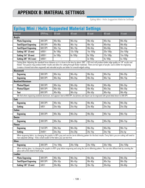
APPENDIX B: MATERIAL SETTINGS
Epilog Mini / Helix Suggested Material Settings
Epilog Mini / Helix Suggested Material Settings
Material
DPI/Freq. 30 watt
40 watt
- 140 -
Appendix B: Material Settings
Epilog Mini / Helix Suggested Material Settings • These are only suggestions: Every type of material will react differently with the laser, even from one plastic to the next. But don’t feel that
Moxa 通用 PCI 多端口串行板快速安装指南(第一版)说明书

Universal PCI Smart Serial Board Quick Installation GuideFirst Edition, October 2017OverviewMoxa’s Universal PCI (UPCI) multiport serial boards can be installed in PCI or PCI-X slots and support both 3.3V and 5VPCI/PCI-X.Package ChecklistUFCI board are shipped with the following items:• 1 Moxa UPCI multiport serial board•Low-profile bracket (low-profile models only)•Documentation and software CD•Quick installation guide (printed)•Warranty cardNOTE Notify your sales representative if any of the above items are missing or damaged.Hardware Installation ProcedureThe Universal PCI board MUST be plugged into the PC before the driver is installed.Follow the steps below:1.Select serial transmission mode. This step is for certainmodels listed below.If your product on hand is not included, please directly go to step2.If your model is CP-112UL Series/ CP-114UL Series / CP-118U Series/ CP-132UL Series/ CP-134U Series/ CP-138U Series,you will need to set onboard DIP switches for each port.(Refer to “Dip Switch Settings” section to complete the DIP switches setting)2.Install the board. Power off the PC and then plug the boardfirmly into any open PCI or PCI-X expansion slot.3.Plug the connection cable into the board’s connector.(Refer to “Pin Assignments” section for the cable pinassignment).4.Start system and verify the driver initialization.Software Installation Information1.Get the driver at or from the CD. Basedon the OS type, choose the corresponding driver.2.Installing the driver:•For Windows OS (Take the installation of Win7 asan example)o 2.1. Unzip and execute the .exe fileo 2.2. Follow the instructions to install thedrivers•For LinuxExecute the following commands from the Linuxprompt:o 2.1. Get the driver from CD and Unzip thefile:#mount /dev/cdrom /mnt/cdrom#cd /#mkdir moxa#cd moxa#cp /mnt/cdrom/<driverdirectory>/mxser.tgz .#tar xvfz mxser.tgzo 2.2. Install the driver:#cd mxser#./mxinstallo 2.3. Verify the driver statusUse the Moxa diagnostic utility to verifythe driver status:#cd /moxa/mxser/utility/diag#./msdiago 2.4. Test the tty portUse the Moxa terminal utility to test thetty ports:#cd /moxa/mxser/utility/term#./mstermDIP Switch SettingsCP-112UL Series /CP-112UL-I SeriesMode S1 S2 S3RS-232 ON - -RS-422 OFF ON -4-Wire RS-485OFF OFF ON2-Wire RS-485OFF OFF OFFCP-114UL Series /CP-114UL-I SeriesMode S1 S2 S3RS-232 - - ONRS-422 - ON OFF4-Wire RS-485ON OFF OFF2-Wire RS-485OFF OFF OFFCP-118U Series /CP-118U-I SeriesMode S1 S2 S3RS-232 - - ONRS-422 ON OFF4-Wire RS-485ON OFF OFF2-Wire RS-485OFF OFFOFFCP-132UL SeriesMode S1 S2 IllustrationRS-422 - OFF2-Wire RS-485ON ON4-Wire RS-485OFF ONNCP-134U Series /CP-134U-I SeriesRS-422 or RS-485 mode:Use the jumper to cover thetwo columns on the left of thejumper pins.RS-232 mode: Use thejumper to cover the twocolumns on the right of thejumper pins.CP-138U Series /CP-138U-I Series Mode S1 S2RS-422 ON 4-Wire RS-485ON OFF 2-Wire RS-485OFF OFF Pin AssignmentsCP-102U SeriesMale DB9 RS-232Pin Signal1 DCD2 RxD3 TxD4 DTR5 GND6 DSR7 RTS8 CTSCP-102UL SeriesFemale DB25 RS-232Pin Signal Pin Signal1 - 14 -2 DCD1 15 DTR13 GND 16 DSR14 CTS1 17 RTS15 RxD1 18TxD16 - 19 -7 - 20 –8 - 21 DCD09 DTR0 22 GND10 DSR0 23 CTS011 RTS0 24 RxD012 TxD0 2513 - - - CP-104JU SeriesRJ45(RS-232)Pin Signal1 DSR2 RTS3 GND4 TxD5 RxD6 DCD7 CTS8 DTRCP-104ULMale DB25 (CBL-M44M25x4-50)Pin RS-2322 TxD3 RxD4 RTS5 CTS6 DSR7 GND8 DCD20 DTR(CBL-M44M9x4-50)(Opt4-M9A)Pin RS-2321 DCD2 RxD3 TxD4 DTR5 GND6 DSR7 RTS8 CTSRJ45(Opt4-RJ45A)Pin RS-2321 DSR2 RTS3 GND4 TxD5 RxD6 DCD7 CTS8 DTRCP-112UL-SeriesMale DB9 (CBL-M25M9x2-50)Pin RS-232 RS-422/RS-485-4WRS-485-2W1 DCD TxD-(A) -2 RxD TxD+(B) –3 TxD RxD+(B) Data+(B)4 DTR RxD-(A) Data+(A)5 GND GNDGND6 DSR--7 RTS - –8 CTS - -9 - - -CP-114UL SeriesMale DB9 (CBL-M44M9x4-50)Pin RS-232 RS-422/485-4W RS-485-2W1 DCD TxD-(A) –2 RxD TxD+(B) –3 TxD RxD+(B) Data+(B)4 DTR RxD-(A) Data-(A)5 GND GND GND6 DSR – –7 RTS – –8 CTS ––Male DB25 (CBL-M44M25x4-50)Pin RS-232 RS-422/RS-485-4WRS-485-2W2 TxD RxD+(B) Data+(B)3 RxD TxD+(B) –4 RTS – –5 CTS – –6 DSR – –7 GND GND GND8 DCD TxD-(A) –20 DTR RxD-(A) Data-(A)CP-118UI Series/CP-138U-I Series Male DB9 (CBL-M78M9x8-100)Pin RS-232* RS-422/RS-485-4WRS-485-2W1 DCD TxD-(A) –2 RxD TxD+(B) –3 TxD RxD+(B) Data+(B)4 DTR RxD-(A) Data-(A)5 GND GND GND6 DSR – –7 RTS – –8 CTS – –*CP-118U-I Series onlyMale DB25 (CBL-M78M25x8-100)Pin RS-232* RS-422/RS-485-4WRS-485-2W2 TxD RxD+(B) Data+(B)3 RxD TxD+(B) –4 RTS – –5 CTS – –6 DSR – –7 GND GND GND8 DCD TxD-(A) –20 DTR RxD-(A) Data-(A)*CP-118U-I Series only CP-118U Series/CP-138U SeriesMale DB9(CBL-M62M9x8-100, Opt8-M9 is for CP-118U and CP-138U)(CBL-M78M9x8-100 is for CP-118U-I and CP-138U-I)Pin RS-232 RS-422/RS-485-4WRS-485-2W1 DCD TxD-(A) –2 RxD TxD+(B) –3 TxD RxD+(B) Data+(B)4 DTR RxD-(A) Data-(A)5 GND GND GND6 DSR – –7 RTS – –8 CTS – –*CP-118U Series onlyMale DB25(CBL-M62M25x8-100, Opt8B is for CP-118U and CP-138U)(CBL-M78M25x8-100 is for CP-118U-I and CP-138U-I)Pin RS-232* RS-422/RS-485-4WRS-485-2W2 TxD RxD+(B) Data+(B)3 RxD TxD+(B) –4 RTS – –5 CTS – –6 DSR – –7 GND GND GND8 DCD TxD-(A) –20 DTR RxD-(A) Data-(A)*CP-118U Series onlyFemale DB25 (OPT8A/S)Pin RS-232 RS-422/RS-485-4WRS-485-2W2 RxD TxD+(B) –3 TxD RxD+(B) Data+(B)4 CTS – –5 RTS – –6 DTR RxD-(A) Data-(A)7 GND GND GND8 DCD TxD-(A) –20 DSR – –*CP-118U Series onlyRJ45 (opt8-RJ45)Pin Signal*1 DSR2 RTS3 GND4 TxD5 RxD6 DCD7 CTS8 DTR*CP-118U Series onlCP-132UL Series/CP-132UL-I SeriesMale DB9 Connector: Device-side Pin AssignmentsPinRS-422RS-485-4W RS-485-2W1 TxD-(A) TxD-(A) –2 TxD+(B) TxD+(B) –3 RxD+(B) RxD+(B) Data+(B)4 RxD-(A) RxD-(A) Data-(A)5 GND RxD-(A) GND6 RTS-(A) GND –7 RTS+(B) – –8 CTS+(B) – –9 CTS-(A) ––/supportThe Americas:+1-714-528-6777 (toll-free: 1-888-669-2872)Europe: +49-89-3 70 03 99-0 Asia-Pacific: +886-2-8919-1230China: +86-21-5258-9955 (toll-free: 800-820-5036)2017 Moxa Inc. All rights reserved.CP-134U SeriesMale DB9 (CBL-M44M9x4-50)Pin RS-232 RS-422/ RS-485- 4W RS-485-2W 1 DCD TxD-(A) TxD-(A) – 2 RxD TxD+(B)TxD+(B) –3 TxD RxD+(B) RxD+(B) Data+(B) 4 DTR RxD-(A) RxD-(A) Data–(A)5 GND GND GND GND6 DSR RTS-(A) –7 RTS RTS+(B) –8 CTSCTS+(B) –9CTS-(A)Male DB25 (CBL-M44M25x4-50)Pin RS-232 RS-422/ RS-485- 4W RS-485-2W 2 TxD RxD+(B) RxD+(B) Data+(B)3 RxD TxD+(B) TxD+(B) –4 RTS RTS+(B) - -5 CTS CTS+(B) - -6 DSR RTS-(A) - -7 GND GND GNDGND8DCDTxD-(A) TxD-(A) – 20 DTR RxD-(A) RxD-(A) Data-(A)22 -CTS-(A)- -CP-168U SeriesRS-232 Cable Wiring for Opt8A/B/C/D/S OPT8A/S(DCE, DB25 Female) PinSignal 2 RxD 3 TxD 4 CTS 5 RTS 6 DTR 7 GND 8 DCD 20DSROPT8-RJ45 (8-pin) PinSignal 1 DSR 2 RTS 3 TxD 4 GND 5 RxD 6 DCD 7 CTS 8DTROPT8B/C (DCE, DB25 Male) PinSignal 2 TxD 3 RxD 4 RTS 5 CTS 6 DSR 7 GND 8 DCD 20DTROPT8-M9, Opt8D(DTE, DB9 Male) Pin Signal 1 DCD 2 RxD 3 TxD 4 DTR 5 GND 6 DSR 7 RTS 8CTSRS-422 Cable Wiring for Opt8FOPT8F/Z(DB25 Female) Pin Signal 2 RxD+(B) 3 TxD+(B) 14 RxD-(A) 16 TxD-(A) 7GNDRS-422/485 Cable Wiring for Opt8KRS-422/RS-485-4WRS-485-2W Pin Signal Pin Signal 2 RxD+(B) 2 Data+(B) 3 TxD+(B) 14 Data-(A) 14 RxD-(A) 7 GND16 TxD-(A) 7 GNDPOS-104UL SeriesMale D89(CBL-M44M9x4-50) Pin RS-232 1 DCD 2 RxD 3 TxD 4 DTR 5 GND 6 DSR 7 RTS 8 CTS9 RI/5V/12V。
GE Vernova Flexipad 产品说明书

FLEXIPADEasier Maintenance, Higher Robustness & Reliability and Better Performance &Compactness thanks to a unique patented pads design and superior PEEK material properties.PEEK shell easily dismountable &replaceableHIGH PERFORMANCE THRUST & GUIDE BEARING PADSADVANCED BEARING TECHNOLOGY•GE Vernova’s Flexipad thrust & guide bearing pads have a sliding surface with a long lasting and high-performance thermoplastic coating.•They advantageously replace conventional babbitt pads, thanks to higher resistance to temperature and pressure, higher dimensional integrity and a lower friction co-efficient.•GE Vernova can upgrade existing babbitt pads to Flexipad by remachining the pads and installing a Flexipad PEEK shell instead of the babbitt coating.Pad repair in less than 1 hour on site Reduction of spare parts inventory: Only thin PEEK shells to be kept as spares5x less wear than PTFE coatings (*)Safe operation without injectionUp to 30% reduction in bearing losses(*) wear measured on our test rig by operating PEEK and PTFE pads in similar conditionsFLEXIPAD BENEFITSEasily & quickly repairable on site:in case of coating damage, one only has to dismount the pad from the bearing, dismount the Flexipad PEEK shell and install a spare one and remount the pad. The pad repair can be done on site in less than 1 hour. There is no need anymore to ship the pads to an external supplier for rebabbittingMore robust & reliable bearings: due to the low thermal conductivity of the Flexipad coating, the bearing pads have smaller thermal deformations compared to conventional materials, allowing a fast unit re-start after a stop. Low friction properties keep units with ageing hydraulic jacking systems operational, despite more starts and stops.More compact, more efficient bearings: with higher thermal and mechanical strengths, new bearings can be downsized and work with significantly higher loads.Reduced upgrade cost: Flexipad’shigh load carrying properties allow to keep existing thrust bearing arrangements and civil works, thus reducing upgrade costs if unit power and weight are increased.Improved peace of mind by solvinghot or problem bearings : Flexipad is more resistant to temperature and pressure, meaning it is less likely to seize up or trip a machine.HIGH PERFORMANCE THRUST & GUIDE BEARING PADSFEATURESFlexipad has a composite coating made from PEEK which improves pad characteristics. The coating is easily dismountable –see picture on the first page –with no need for any specific tooling.GE Vernova recommends the use of Flexipad pads for all Guide & Thrust bearings in vertical and horizontal arrangements. In particular Flexipad is particularly suited •To solve bearing issues such as overheating of the bearing: as it allows for higher specific pressure and reduced oil temperature increase•In refurbishment in case of increase of rotation speed or thrust load•For new bearings to reduce friction lossesFLEXIPADCONTACT US************************+ 1855 522 0755PEEK COATING SUPERIOR CHARACTERISTICS•High temperature resistance and maintenance of characteristics at higher temperatures •Tough material with lowdeformation, low wear and creep for a longer life-time•Very high load carrying capacity •Low friction co-efficient improves sliding propertiesMain CharacteristicsPEEK*Babbitt**PTFE***Melting point (°C)341240327Tensile strength room temp. (MPa)24022Tensile strength at 100°C. (MPa)15015Seizure, max. load (MPa)≥25 3.5w orking pressure 14Friction coefficient in oil0.0510.20.043Wear (based on comparative wear test)~2µm ~11µm Elongation2%300%Hardness (Rockwell)12620* PolyEtherEtherKetone ** or ‘White Metal’ *** PolyTetraFluoroEthylene, or Teflon®FEEDBACK FROM THE FIELD20 years experience with PEEK coated pads. Flexipad itself was first installed on a hydro unit in 2018. 14 thrust bearings & 3 guide bearings have been equipped worldwide with Flexipad pads for units from 4 MW to 188 MW, 75 rpm to 600 RPM. Examples:•Thrust bearing failure on Swiss unit in 2017. Due to low-speed rotation of the rotor for several hours after a guide vane failure. The mechanism got locked and was not able to close completely due to debris that entered between the blades. GE Vernova a solution based on PEEK material. •Test simulated bearing seizure due to lack of lubricating oil. In this scenario during operation with 4 MPa and 800 rpm the oil was removed from thebearing housing. The bearing continued to operate for 15 minutes. The surface was only slightly worn without any catastrophic damage visible.。
MGate 5118系列快速安装指南说明书

P/N: 1802051180013 *1802051180013*MGate 5118 Series Quick Installation GuideVersion 1.3, February 2023Technical Support Contact Information/support2023 Moxa Inc. All rights reserved.OverviewThe MGate 5118 is an industrial Ethernet gateway for J1939-to-Modbus RTU/ASCII/TCP, PROFINET and EtherNet/IP network communications. Package ChecklistBefore installing the MGate 5118, verify that the package contains the following items:• 1 MGate 5118 gateway•Quick installation guide (printed)•Warranty cardPlease notify your sales representative if any of the above items is missing or damaged.Optional Accessories (can be purchased separately)•Mini DB9F-to-TB: DB9-female-to-terminal-block connector •WK-51-01: Wall-mounting kit, 51 mm wideHardware IntroductionLED IndicatorsLED Color DescriptionPWR 1, PWR 2 Green The power cable is connected Off The power cable is disconnectedReady Off Power is off or a fault condition existsGreen Steady on: Power is on, and the unit is functioningnormallyBlinking: The unit is responding to the software’sLocate functionRed Steady on: Power is on, and the unit is booting upBlinking: Indicates an IP conflict, or the DHCP orBOOTP server is not responding properlyFlashing quickly: the microSD card failedLAN Green(Flashingonly) The Ethernet port is receiving or transmitting data Modbus TCP Client:Modbus communication in progressModbus TCP Server:Modbus communication in progressEIP Scanner:I/O is exchanging data with at least one device EIP Adapter: I/O is exchanging data PROFINET: PROFINET I/O interface is exchanging dataLED Color DescriptionRed (Flashing only) A communication error occurredModbus TCP Client:1.Received an exception code or framing error(parity error, checksum error)mand timeout (slave device is notresponding)3.TCP connection timeoutModbus TCP Server:1.Received an invalid function code or framingerror (parity error, checksum error)2.Accessed invalid register address or coil address Ethernet/IP Scanner:mand timeout (the adapter is notresponding)2.TCP connection timeoutEthernet/IP Adapter:The connection was refused due to incorrect configurationOff No communicationMB* Green(Flashingonly)Modbus is receiving or transmitting dataRed (Flashing only) A communication error occurredMaster Mode:1.Received an exception code or framing error(parity error, checksum error)mand timeout (the slave device is notresponding)Slave Mode:1.Received an invalid function code or framingerror (parity error, checksum error)2.Accessed invalid register address or coil addressOff No communicationCAN Green(Flashingonly) CANbus(J1939) communication is receiving or transmitting dataRed (Steady) A communication error occurred1.The J1939 address claim failed2.CAN is in bus-off state because the error counteris exceeding its limitationsOff No communicationEth1, Eth2 Green Indicates a 100 Mbps Ethernet connection Amber Indicates a 10 Mbps Ethernet connection Off The Ethernet cable is disconnected*Only indicates serial communication status; for Modbus TCP status, please refer to LAN LED indicator.DimensionsUnit = mm (inch)Reset ButtonRestore the MGate to factory default settings by using a pointed object (such as a straightened paper clip) to hold the reset button down until the Ready LED stops blinking (approximately five seconds).Pull-high, Pull-low, and Terminator for RS-485 and CANOn the MGate 5118’s left side panel, you will find DIP switches to adjust each CAN port or serial port’s pull-high resistor, pull-low resistor, and terminator.SWCANMODBUS1 2 3 12 3 Pull-high resistor Pull-low resistor TerminatorPull-highresistorPull-lowresistor TerminatorON Reserved120 Ω(default)1 kΩ1 kΩ120 ΩOFF –150 kΩ(default)150 kΩ(default)– (default)Hardware Installation Procedure1. Connect the power adapter. Connect the 12-48 VDC power line orDIN-rail power supply to the MGate 5118’s terminal block. 2. Use a serial cable to connect the MGate to the Modbus or CANdevice.3. Use an Ethernet cable to connect the MGate to the Modbus,Ethernet/IP or PROFINET device.4. The MGate 5118 is designed to be attached to a DIN rail ormounted on a wall. For DIN-rail mounting, push down the spring and properly attach it to the DIN rail until it “snaps” into place. For wall mounting, install the wall-mount kit (optional) first and then screw the device onto the wall. The following figure illustrates the two mounting options:Software Installation InformationYou can download the User's Manual and DSU (Device Search Utility) from Moxa's website: . Please refer to the User’s Manual for additional details on using the Device Search Utility. The MGate 5118 also supports login via a web browser. Default IP address: 192.168.127.254 Default account: admin Default password: moxaPin AssignmentsModbus Serial Port (Male DB9)PinRS-232RS-422/ RS-485 (4W)RS-485 (2W) 1 DCD TxD-(A) – 2 RXD TxD+(B) –3 TXD RxD+(B) Data+(B)4 DTR RxD-(A) Data-(A) 5* GND GND GND 6 DSR – – 7 RTS – – 8 CTS – – 9 – ––*Signal groundCAN Port (6-pin Terminal Block)Pin CAN 1 CAN_L 2 CAN_H 3 CAN Signal GND 4 Ext-CAN_L* 5 Ext-CAN_H* 6 CAN_SHLD* For the CAN port, plug CAN_L and CAN_H into the terminal block. If another device is connected to the same CAN bus, use the Ext_CAN_L and Ext_CAN_H as extension pins.Ethernet Port (RJ45) Pin Signal 1 Tx+ 2 Tx- 3 Rx+ 6Rx-Console Port (RS-232)The MGate 5118 series can use a RJ45 serial port to connect to a PC to configure the device. PinSignal 1 DSR 2 RTS 3 GND 4 TXD 5 RXD 6 DCD 7 CTS 8DTRPower Input and Relay Output PinoutsV2+V2-V1+V1-ShieldedGroundDC Power Input 2 DCPower Input 2 N.O.CommonN.C. DC Power Input 1 DCPowerInput 1SpecificationsPower RequirementsPower Input 12 to 48 VDCPower Consumption 12 to 48 VDC, 416 mA (max.) Operating Temperature Standard model:0 to 60°C (32 to 140°F)Wide temperature model:-40 to 75°C (-40 to 167°F)Ambient Relative Humidity 5 to 95% RHDimensions 45.8 x 105 x 134 mm (1.80 x 4.13 x 5.27in)ReliabilityAlert Tools Built-in buzzer and RTCMTBF 727,873 hrs.NOTE In the following section, ATEX and C1D2 certifications will be detailed separately.ATEX Information1.ATEX Certificate number: DEMKO 17 ATEX 1848XIECEx Certificate number: IECEx UL 17.0019X2.Ambient Temperature Range:0°C to 60°C (for models without suffix –T)-40°C to 75°C (for models with suffix –T only)3.Certification String: Ex ec nC IIC T4 Gc4.Standards Covered:IEC 60079-0, Edition 7IEC 60079-7, Edition 5.1IEC 60079-15, Edition 5EN IEC 60079-0: 2018EN IEC 60079-7: 2015 + A1: 2018EN IEC 60079-15: 20195.The conditions for safe use:a.Ethernet communications devices are intended for mounting ina tool-accessible IP54 enclosure and use in an area of not morethan pollution degree 2 as defined IEC/EN 60664-1.b.Conductors suitable for use in an ambient temperature greaterthan 85°C must be used for the power supply terminals.c. A 4 mm² conductor must be used when a connection to theexternal grounding screw is used.d.Provisions shall be made, either in the equipment or external tothe equipment, to prevent the rated voltage from exceeding thetransient disturbances by over 140% of the peak-rated voltage. Installation instructionsWhen wiring the relay contact (R), digital input (DI), and power inputs (P1/P2), we suggest using American Wire Gauge (AWG) 16 to 20 as a cable and the corresponding pin-type cable terminals. The strippinglength is recommended to be 8 to 9 mm. The wire temperature rating should be at least 85°C. The shielding ground screw (M4) is near the power connector. When you connect the shielded ground wire (min. 16 AWG), the noise is routed from the metal chassis to the ground.C1D2 Information1.These devices are open-type devices that are to be installed in anenclosure only accessible with the use of a tool and suitable for the environment.2.This equipment is suitable for use in Class I, Division 2, Groups A,B, C, and D or non-hazardous locations only.”Moxa Inc.No. 1111, Heping Rd., Bade Dist., Taoyuan City 334004, Taiwan。
Schneider Electric RM4UA33M 电压测量电磁遥控器说明书

T h e i n f o r m a t i o n p r o v i d e d i n t h i s d o c u m e n t a t i o n c o n t a i n s g e n e r a l d e s c r i p t i o n s a n d /o r t e c h n i c a l c h a r a c t e r i s t i c s o f t h e p e r f o r m a n c e o f t h e p r o d u c t s c o n t a i n e d h e r e i n .T h i s d o c u m e n t a t i o n i s n o t i n t e n d e d a s a s u b s t i t u t e f o r a n d i s n o t t o b e u s e d f o r d e t e r m i n i n g s u i t a b i l i t y o r r e l i a b i l i t y o f t h e s e p r o d u c t s f o r s p e c i f i c u s e r a p p l i c a t i o n s .I t i s t h e d u t y o f a n y s u c h u s e r o r i n t e g r a t o r t o p e r f o r m t h e a p p r o p r i a t e a n d c o m p l e t e r i s k a n a l y s i s , e v a l u a t i o n a n d t e s t i n g o f t h e p r o d u c t s w i t h r e s p e c t t o t h e r e l e v a n t s p e c i f i c a p p l i c a t i o n o r u s e t h e r e o f .N e i t h e r S c h n e i d e r E l e c t r i c I n d u s t r i e s S A S n o r a n y o f i t s a f f i l i a t e s o r s u b s i d i a r i e s s h a l l b e r e s p o n s i b l e o r l i a b l e f o r m i s u s e o f t h e i n f o r m a t i o n c o n t a i n e d h e r e i n .Product data sheetCharacteristicsRM4UA33Mvoltage measurement relay RM4-U - range30..500 V - 220..240 V ACMainRange of product Zelio ControlProduct or component type Industrial measurement and control relays Relay type Voltage measurement relay Relay name RM4URelay monitored pa-rameters Overvoltage or undervoltage detection Time delayAdjustable 0.05...30 s Power consumption in VA2.7...3.4 VA ACMeasurement range50...500 V voltage DC 30...300 V voltage DC50...500 V voltage AC 50/60 Hz 30...300 V voltage AC 50/60 Hz Contacts type and com-position2 C/OComplementary[Us] rated supply voltage 220...240 V AC, 50/60 Hz +/- 5 %Output contacts 2 C/OInternal input resistance1111000 Ohm 11110000 Ohm 668000 Ohm Permissible continuous overload 400 V 550 VPermissible non repetitive overload 550 A for <= 1 s 500 A for <= 1 s Setting accuracy of the switching threshold +/-5 %Switching threshold drift <= 0.5 % within the supply voltage range (0.85...1.1 Un)<= 0.06 % per degree centigrade depending permissible ambient air temperature Setting accuracy of time delay 10 PTime delay drift <= 0.5 % within the supply voltage range (0.85...1.1 Un)<= 0.07 % per degree centigrade depending on the rated operational temperature Hysteresis 5...30 % adjustable of voltage threshold setting Quality labels CEOvervoltage category III conforming to IEC 60664-1[Ui] rated insulation voltage 500 V conforming to IEC Operating voltage tolerance 0.85...1.1 Uc Supply disconnection value > 0.1 UcOperating position Any position without deratingConnections - terminals Screw terminals 2 x 2.5 mm², flexible cable without cable end Screw terminals 2 x 1.5 mm², flexible cable with cable end Tightening torque 0.6...1.1 N.m Mechanical durability<= 30000000 cycles [Ith] conventional free air thermal current8 A[Ie] rated operational current0.3 A at 115 V DC-13 70 °C conforming to VDE 06600.3 A at 115 V DC-13 70 °C conforming to IEC 60947-5-1/19910.1 A at 250 V DC-13 70 °C conforming to VDE 06600.1 A at 250 V DC-13 70 °C conforming to IEC 60947-5-1/19913 A at 250 V AC-15 70 °C conforming to VDE 06603 A at 250 V AC-15 70 °C conforming to IEC 60947-5-1/19913 A at 24 V AC-15 70 °C conforming to VDE 06603 A at 24 V AC-15 70 °C conforming to IEC 60947-5-1/19913 A at 115 V AC-15 70 °C conforming to VDE 06603 A at 115 V AC-15 70 °C conforming to IEC 60947-5-1/19912 A at 24 V DC-13 70 °C conforming to VDE 06602 A at 24 V DC-13 70 °C conforming to IEC 60947-5-1/1991 Switching capacity in mA10 mA at 12 VSwitching voltage250 V AC<= 440 V ACContacts material90/10 silver nickel contactsNumber of cables2Height78 mmWidth22.5 mmDepth80 mmTerminals description ISO n°1(15-16-18)OC(25-26-28)OC(A1-A2)CO(C-B2-B3)COOutput relay state Tripped if A measured > A set9 mm pitches 2.5Product weight0.168 kgEnvironmentStandards EN/IEC 60255-6Product certifications CSAGLULDirectives89/336/EEC - electromagnetic compatibility73/23/EEC - low voltage directiveAmbient air temperature for storage-40...85 °CAmbient air temperature for operation-20...65 °CRelative humidity15...85 % 3K3 conforming to IEC 60721-3-3Vibration resistance0.35 ms (f = 10...55 Hz) conforming to IEC 60068-2-6Shock resistance15 gn for 11 ms conforming to IEC 60068-2-27IP degree of protection IP50 (casing) conforming to IEC 60529IP20 (terminals) conforming to IEC 60529Pollution degree 3 conforming to IEC 60664-1Dielectric test voltage 2.5 kVNon-dissipating shock wave 4.8 kVResistance to electrostatic discharge8 kV air conforming to IEC 61000-4-2 level 36 kV contact conforming to IEC 61000-4-2 level 3 Resistance to electromagnetic fields10 V/m conforming to IEC 61000-4-3 level 3Resistance to fast transients 2 kV conforming to IEC 61000-4-4 level 3Protection against electric shocks 2 kV : level 3 conforming to IEC 61000-4-5Disturbance radiated/conducted CISPR 11 group 1 - class ACISPR 22 - class ADimensions DrawingsVoltage Measurement Relays DimensionsMounting and ClearanceVoltage Measurement Relays Rail mountingScrew fixingConnections and SchemaVoltage Measurement RelaysRM4UA01 and RM4UA02 Wiring DiagramA1-A2Supply voltage B1,B2,B3, CVoltages to be measured (see table below)RM4UA03 Wiring DiagramA1-A2Supply voltage B2,Voltages to be measured (see table below)RM4UA31 and RM4UA32 Wiring DiagramA1-A2Supply voltage B1,B2,B3, CVoltages to be measured (see table below)RM4UA33 Wiring DiagramA1-A2Supply voltage B2,Voltages to be measured (see table below)Voltage Measurement Relays Application SchemeExample: overspeed monitoring (undervoltage function)(1)Tachogenerator (2)OverspeedPerformance CurvesElectrical Durability and Load Limit Curves AC LoadCurve 1: Electrical durability of contacts on resistive load in millions of operating cyclesX Current broken in AY Millions of operating cyclesCurve 2: Reduction factor k for inductive loads (applies to values taken from durability Curve 1)X Power factor on breaking (cos φ)Y Reduction factor KDC LoadLoad limit curveX Current in A Y Voltage in V 1L/R = 20 ms2L/R with load protection diode 3Resistive loadTechnical DescriptionFunction DiagramOvervoltage ControlFunction “>”Legendt Time delayU A1-A2 Supply voltageUS1 Setting voltage thresholdUS2 Voltage measured15-18, 15-16; 25-28, 25-26 Output relays connections Relay status: black color = energized.Function DiagramUndervoltage ControlFunction “<”Legendt Time delayU A1-A2 Supply voltageUS1 Setting voltage thresholdUS2 Voltage measured15-18, 15-16; 25-28, 25-26 Output relays connections Relay status: black color = energized.。
- 1、下载文档前请自行甄别文档内容的完整性,平台不提供额外的编辑、内容补充、找答案等附加服务。
- 2、"仅部分预览"的文档,不可在线预览部分如存在完整性等问题,可反馈申请退款(可完整预览的文档不适用该条件!)。
- 3、如文档侵犯您的权益,请联系客服反馈,我们会尽快为您处理(人工客服工作时间:9:00-18:30)。
GLOBAL QUALITYSurface Coating: All layers of materials such as paint or similar materials, that dry to a solidfilm when applied to a substrate and that can be scraped off with a sharp blade or washed offwith a solvent such as acetone or ethanol, without removing the substrate (base) material.NOTE: Labels are not considered surface coatings because they do not meet the definition of a surface coating in 16 CFR 1303. Labels may contain surface coatings—those coatings shouldbe tested according to QSOP 0006-3600, Heavy Elements §2.2.3 Surface Coatings. The basematerial of the label should be tested according to the appropriate section for substrates (e.g.22.2.2 AA or ICP may be used instead of XRF device and test results evaluation must beconducted per § 3.3.1*Report No.: CM Substrate XRF001, “Verification of Total Lead in Substrates by XRF” (2008), MAPS Conformance Laboratory Report; Report No.: CM Substrate XRF002, “Verification of Total Cadmium in Substrates by XRF” (2010), MAPS Conformance Laboratory Report2.3 Subcontractors2.3.1 Verify compliance per GQMP 0006-2140, Subcontractors - Vendors.2.3.1.1 Subcontracting on PVC rotocasting or PVC injection molding is allowed priorfactory approval by Mattel.2.3.2 If a certified supplier becomes a Subcontractor at the same time, then the source maybe treated as …Supplier‟ if the subcontracting process is audited and certified by Mattel(Reference GQMP 0006-2115, Supplier Certification Process).2.4 Any test failure must be reported per GQMP 0006-2108, Failure Track.2.5 Mattel production must be clearly segregated.Example of segregation: different room or separated by floor markings or signs.2.6 Test records must be retained for 5 years from the date of creation.2.7 Vendors must purchase materials and components from a certified supplier if an adequatecertified category exists unless an approval has been granted per GQMP 0006-2002, Productand Process Deviations.On-hand inventory and forthcoming deliveries from purchase orders released prior notificationcan be used (Deviation is not required). Supporting documentation (e.g., purchase orders,receiving records) must be available upon request.3 TEST METHODS3.1 Test Environment (N/A)3.2 Equipment (N/A)3.3 General Test Requirements3.3.1 Testing using AA or ICP must be performed per QSOP 0006-3600, Heavy Elements orQSOP 0006-3604, Heavy Elements - Children‟s Jewelry or QSOP 0006-3606, HeavyElements - Children‟s We aring Apparel or QSOP 0006-3607, Heavy Elements -Children‟s Cosmetics or RMS 0006-2902, Zinc or RMS 0006-2903, Colorants.3.3.2 Testing using XRF must be performed per GLOP 0006-7402, XRF Operating Procedure.3.3.3 Materials and Components Identification (Reference Appendix 1)Each storage bin (i.e., bin in which materials are stored or transported; a.k.a., pallet,bundle) shall be identified as either “Accepted”, “Hold - ICP Pending” or “Rejected”. Onlyone label (i.e., accepted, hold - ICP pending or rejected) must be visible at any time.“Hold - ICP Pending” labe l is to be used when a XRF test fails and AA/ICP is used toconfirm results.3.4 ProcedureHE SubstratesFlowChart3.4.1 Incoming Inspection at Vendor3.4.1.1 Purchased materials or components3.4.1.1.1 Certified SupplierIf a Mattel certified supplier exists, Vendors must purchase materialsor components from them. NOTE: Add …For Mattel Product‟ whenplacing a purchase order (P.O.).Testing is to be conducted by the Supplier and its frequencydetermined by the Mattel Audit Team during the supplier certificationprocess.3.4.1.1.2 Non-Certified Supplier∙Every delivery of materials/components listed in Appendix 2received from a non-certified supplier must be tested at incominginspection.If a delivery contains parts that are identified (e.g., batch code,date code), test each identified part separately.∙For any other material/component not listed in Appendix 2,Vendors are required to develop and implement a documentedquality system to ensure compliance with Mattel Heavy Elementrequirements.3.4.1.2 Components sourced from a Mattel Owned and Operated Plant or anotherVendor factory3.4.1.2.1 Components sourced from a Mattel Owned and Operated Plantmust be accompanied by a test report prior to use following a testingfrequency at least every 6 months.3.4.1.2.2 Components sourced from another Vendor must be accompanied bya test report prior to use following a testing frequency per § 3.4.23.4.1.3 Components sourced from a Vendor-Approved Subcontractor3.4.1.3.1 Test every material type sourced from a Subcontractor.Exemption: Materials/Components that were not undergone achemical transformation/treatment (e.g., sewing process, assembly).3.4.1.3.1.1 Test must be conducted using XRF (Sample Size = 1)only for Lead (Pb) (Applicable to plastic, fabric, paperand wood) according to the criteria per § 2.2. For anyother substrate, use AA or ICP and test only for Lead(Pb).Components must be tested at incoming inspection according to thefollowing frequency:Subcontractors of Electroplating, Insert Molding, Flocking or FabricLamination∙Test every delivery.Others∙State 1. Test 1st delivery. Multiple deliveries, same part number,occurring during the same day are considered as “one delivery”.∙State 2. If the test passes, test once per month.Starting 1/1/2011 (all Subcontractors) →∙State 1. Test 3 consecutive deliveries. Multiple deliveries, samepart number, occurring during the same day are considered as“one delivery”.∙State 2. If the test passes, test once per week for 5 consecutivetimes.∙State 3. If the test passes, test every 2 weeks or any time if45 FREQUENTLY ASKED QUESTIONS (NONE)The labels must be a minimum of 11 cm X 6 cm (4.4 in X 2.4 in). Exemptions to label size are permitted due to the overall size and shape of the material‟s package.Non Certified Suppliers。