款别克昂科雷发动机电气部分原厂维修手册(英文)
别克昂科雷轿车用户手册13
告诫 即使发动机没有运行,电动冷却风扇 也有可能起动。 在发动机舱盖下的电 动风扇旁边操作时必须当心。
5 -3
3. 现在打开发动机舱盖,找到蓄电池 正极 (+) 和负极 (-) 接线柱。
告诫
风扇或其它发动机运动部件会严重伤 人。 发动机运转时不要让手靠近运动 部件。
告诫
检查跨接电缆,不能出现一点松动或 绝缘皮破损。 否则,您可能会触电并 损坏车辆。
4. 将正极 (+) 红色电缆连接到没电的蓄 电池正极 (+) 接线柱上。或连接到分 离式正极 (+) 接线柱上 (如装备)。
7. 将负极电缆的另一端固定在发动机 的重金属上。 将电缆固定在距离没 电蓄电池至少 45 厘米 (18 英寸) 的地方,并远离发动机移动的零件。
注意 忽视这些步骤会损坏车辆。 由此产生的修理费用不在保修范围内。
1. 使两车靠近,跨接电缆能够接上。 确保两车互不接触。
告诫 为保证车辆不会移动,在跨接起动时, 使用两车驻车制动器。 在使用驻车制动器前,自动变速器挂 入 P (驻车)档,手动变速器挂入 N (空)档。
2. 关闭两车的点火开关。关闭收音机 和所有不需要的灯。 拔掉插接在点烟器或附件电源插座 中的任何附件插头。
拆卸千斤顶和举升工具............................................... 5-10
备用轮胎拆卸............................................................. 5-10 更换瘪胎 .................................................................... 5-12 存放轮胎和举升设备 .................................................. 5-15 辅助卡钩系统............................................................. 5-17 紧凑型备胎 ................................................................ 5-19 摆脱陷车 .................................................................... 5-20 数据采集和事件数据记录器 .................................... 5-20
2005-06 Chevrolet Cobalt L4-2.2L 引擎修理手册说明书

69-4515TS TOOLS NEEDED:1. Turn off the ignition and disconnect the negativebattery cable.NOTE: Disconnecting the negative battery cableerases pre-programmed electronic memories.Write down all memory settings beforedisconnecting the negative battery cable. Someradios will require an anti-theft coded to beentered after the battery is reconnected. Theanti-theft code is typically supplied with yourowner’s manual. In the event your vehicles’anti-theft code cannot be recovered, contact anauthorized dealership to obtain your vehiclesanti-theft code.TO START:®CHEVROLET2005-06 CobaltL4-2.2L1/2” Wrench10mm Socket17mm Socket10mm WrenchExtensionPliersRatchetT-30 Torx SocketFlat Blade Screwdriver2. Remove the oil filler cap as shown.3. Pull firmly upwards to release the engine coverand remove from vehicle.NOTE: Replace oil filler cap.4. Disconnect the mass air sensor electricalconnection.5. Loosen the hose clamp at the throttle body.6. Unclip the airbox fastening clips.6a. On models with air injection release the clampand disconnect the air injection pump hose fromthe airbox.7. Release clamp and remove crankcase venthose.8. Unclip airbox mounting clip.AB CDG EFGHVJJIVGDGD KH GFQ GDMMNLUWPOTSRRRNOTE: FAILURE TO FOLLOW INSTALLATION INSTRUCTIONS AND NOT USING THE PROVIDED HARDWARE MAY DAMAGE THE INTAKE TUBE, THROTTLE BODY AND ENGINE.If you need any assistance please call 1-800-858-3333 to speak with a representativein our Customer Service Center before returning the product.Description Qty. Part # Description Qty. Part # Description Qty. Part #A AIR FILTER1RU-5147B HOSE CLAMP #80108694C FILTER ADAPTER - #350121510D NUT 6MM NYLOCK, SS607553E BRACKET “L” SMALL, STL1010031F STUD RUBBER MNT., M/F2070228G WASHER 6MM WAVE, SS808277H BOLT 6MM-1.00 X 12MM HEX207863I HEAT SHIELD107334-1J STUD; 6MM-1.00 X 35MM L, SS408220K BOLT M4 X .7 X 8MM, BUTTON207741L TUBE 2-3/4”OD X 20”L, AL.127508-1TSM HOSE CLAMP #6 MINI208407N HOSE 1/2”ID X 9”L, BLACK108401O HOSE CLAMP #44 SS108560P HOSE 69-4515, 2-3/4”ID TO 3” 1084087Q BRACKET 69-4515, L, STL1020001R HOSE CLAMP #16308413S HOSE; 1”ID X 4-1/2”L, BLACK 108479T VENT, STRT.; 1” X 1”, BARBED108296U CAPLUG; 15/16” ID, 3/4” L, BLK.108246V GASKET; 63-1034, 1/16” NEO209202W HOSE CLAMP #48108601 PARTS LIST:12. Remove the head light mounting bolt and retainas it will be reused.13. On models NOT equipped with air injection,install the provided cap onto the 1” vent fitting andsecure with the provided hose clamp.NOTE: You may now proceed to step #17.14. On models with air injection, disconnect theair injection pump plastic hard line from the airinjection rubber hose.15. On models with air injection, install the 1.0”hose mender into the provided air injection hose(08479) and secure with the provided hose clamp.16. On models with air injection, attach the airinjection hose assembly to the factory rubber airinjection hose and secure with provided hoseclamp.18. With the provided hardware, assemble thestuds onto adapter as shown.19. With the provided hardware, assemble thefilter adaptor and gaskets onto the heat shield andintake tube as shown.20. Install the silicone hose and hose clamps ontothe intake tube as shown.21. Install the rubber mounted stud and small“L” bracket onto the heat shield using suppliedhardware. Do not tighten completely at this time.22. Install the rubber mounted stud and “L” bracketonto the heat shield with the provided hardware.Do not tighten completely at this time.23. Secure the K&N® air filter onto the filter adapterand secure with provided hose clamp.NOTE: Drycharger® filter wrap; part # RU-5147DK is available to purchase separately. Tolearn more about Drycharger® filter wraps orlook up color availability please visit http://www.®24. Install the intake tube assembly, attaching thesilicone hose onto the throttle body as shown.25. Align the heat shield bracket onto the head lightmounting hole and secure it with stock bolt fromstep #12.26. Align the heat shield bracket onto the stockairbox mounting stud and secure it with the stockbolt from step #10.11. Remove mass air sensor from stock intaketube.17. Install the mass air sensor onto the K&N®intake tube with provided hardware.9. Lift firmly upwards and remove airbox fromvehicle.10. Loosen and remove the two airbox retainingnuts then remove the airbox from vehicle.NOTE: K&N Engineering, Inc., recommends thatcustomers do not discard factory air intake.* FREE K&N decal To register your warranty, please see us online at /register. FREE K&N decal *• 1455 CITRUS ST., P.O. BOX 1329, RIVERSIDE, CA., U.S.A. 92502 • TECH SERVICE 800-858-3333 • FAX 951-826-4001•e-mail:******************® • WWW: ®18557M 9/20/16。
5EFE_Engine_Repair_Manual 发动机修理手册

EM18U-01P19776CO/HC Meter-ENGINE MECHANICAL CO/HCEM-1CO/HCINSPECTION HINT:This check is used only to determine whether or not the idle CO/HC complies with regulations.1.INITIAL CONDITIONS (a)Engine coolant at normal operating temperature (b)Air cleaner installed (c)All pipes and hoses of air induction system connected (d)All accessories switched OFF (e)All vacuum lines properly connected (f)SFI system wiring connectors fully plugged (g)Ignition timing set correctly (h)Transmission in neutral position (i)CO/HC meter calibrated by hand 2.START ENGINE 3.RACE ENGINE AT 2,500 RPM FOR APPROX. 180SECONDS 4.INSERT CO/HC METER TESTING PROBE AT LEAST 40 cm (1.3 ft) INTO TAILPIPE DURING IDLING 5.IMMEDIATELY CHECK CO/HC CONCENTRATION AT IDLE AND/OR 2,500 RPM HINT:When doing the 2 mode (2,500 rpm and idle) test, follow the measurement order prescribed by the applicable local regula-tions.EM-2ENGINE MECHANICAL CO/HC-If the CO/HC concentration does not comply with regulations,troubleshoot according to the table below. Check and correctthe cause if necessary.V08293EM0KB-04A05758Compression GaugeCOMPRESSION INSPECTION HINT:If there is lack of power, excessive oil consumption or poor fuel economy, measure the compression pressure.1.WARM UP AND STOP ENGINE Allow the engine to warm up to normal operating temperature.2.REMOVE SPARK PLUGS (See page IG-1)3.CHECK CYLINDER COMPRESSION PRESSURE (a)Insert a compression gauge into the spark plug hole.(b)Fully open the throttle.(c)While cranking the engine, measure the compression pressure.HINT:Always use a fully charged battery to obtain engine revolutions of 250 rpm or more.(d)Repeat steps (a) through (c) for each cylinder.NOTICE:This measurement must be done in as short a time as pression pressure:1,275 kPa (13.0 kgf/cm 2, 185 psi) or more Minimum pressure:981 kPa (10.0 kgf/cm 2, 142 psi)Difference between each cylinder:100 kPa (1.0 kgf/cm 2, 14 psi) or less (e)If the cylinder compression in one or more cylinders is low,pour a small amount of engine oil into the cylinder through the spark plug hole and repeat steps (a) through (c) for cylinders with low compression.L If adding oil helps the compression, chances are that the piston rings and/or cylinder bore are worn or damage.L If pressure stays low, a valve may be sticking or seating is improper, or there may be leakage past the gasket.4.REINSTALL SPARK PLUGSEM0JU-04S05888Charcoal CanisterVSV for EVAP Tie Rod End Battery Front Exhaust PipeLH Engine Under CoverRH Engine Under CoverCompression SpringL GasketRadiatorUpperSupport M/T A/C Compressor Heated Oxygen Sensor(Bank 1 Sensor 2)Clamp L Gasket Compressor Mounting BracketThrottle Cable (A/T)Drive ShaftRadiatorUpperSupportRadiatorIdler Pulley Bracketw/ A/C and w/ o PSAdjusting StrutPS PumpHood L Non-reusable part AcceleratorCableA/T L Snap Ring Air Cleaner AssemblyL Oil Cooler Hose (A/T)ENGINE UNITCOMPONENTSRH Engine Mounting Insulator MAP sensor Hose Brake Booster Vacuum HoseHeater HoseIdle-Up Air Hose (PS)Rear Engine Mounting BracketFuel InletHoseHole Cover Ground StrapClutch Release CylinderSpeedometer CableStarterSpeedometer Cable Starter Control Cable Control CableGround Strap LH Engine Mounting BracketA/T LH Engine Mounting BracketTransaxle x 3Lx 6Ground Strap Clutch CoverClutch DiscM/TL TransaxleLx 3x 5x 6LEM-54-ENGINE MECHANICAL ENGINE UNITEM0JV-03S05838S05848S05840-ENGINE MECHANICAL ENGINE UNITEM-55REMOVAL1.REMOVE BATTERY 2.REMOVE HOOD3.REMOVE ENGINE UNDER COVERS4.DRAIN ENGINE COOLANT5.DRAIN TRANSAXLE OIL (FLUID)6.DISCONNECT VSV FOR EVAP BRACKET7.REMOVE AIR CLEANER ASSEMBLY WITH AIR INTAKE CONNECTOR8.REMOVE RADIATOR (See page CO-16)9.DISCONNECT ACCELERATOR CABLE 10.DISCONNECT FUEL HOSE Remove the union bolt and gaskets, and disconnect the fuel in-let hose.NOTICE:Catch leaking fuel in a container.11.DISCONNECT HOSES Disconnect these hoses:L Brake booster vacuum hose L MAP sensor hose L Heater hoses 12.DISCONNECT SPEEDOMETER CABLE FROM TRANSAXLE 13.w/ PS:DISCONNECT IDLE-UP AIR HOSES FROM AIR CONTROL VALVE 14.DISCONNECT ENGINE WIRE HARNESS Disconnect these connectors and wires:L Oxygen sensor connector L Oil pressure switch connector L Engine coolant temperature sender gauge connector L Engine coolant temperature sensor connector L Camshaft position sensor connector L Fan engine coolant temperature switch connector L A/T only:Lock-up solenoid connector L A/T only:S06150M/T onlyP20565M/TA132 LA/TA242 LA/T EM-56-ENGINE MECHANICAL ENGINE UNITLM/T only:Backup light switch connector L A/T only:No.2 vehicle speed sensor connector L Ground strap L Throttle position sensor connector L IAC valve connector L Injector connectors L Crankshaft position sensor connector L Knock sensor connector L Starter connector and wire L Generator connector and wire 15.M/T only:REMOVE CLUTCH RELEASE CYLINDER WITHOUT DISCONNECTING TUBE (a)Remove the 3 bolts, release cylinder and tube from the transaxle.(b)Disconnect the ground strap.16.M/T:DISCONNECT CONTROL CABLE(S) FROM TRANS-AXLE (a)Remove the clip and plate washer.(b)Remove the retainer from the cable.17.A/T:DISCONNECT CONTROL CABLE(S) FROM TRANS-AXLE (a)Remove the clip and plate washer.(b)Remove the 2 bolts from the LH engine mounting bracket.P20577P20292P20164P20246-ENGINE MECHANICAL ENGINE UNITEM-5718.w/ PS:REMOVE PS PUMP WITHOUT DISCONNECTING HOSES (a)Loosen the 2 bolts, and remove the PS drive belt.(b)Remove the 2 bolts, and disconnect the PS pump from the engine.HINT:Put aside the PS pump, and suspend it.19.w/ A/C:REMOVE A/C COMPRESSOR (a)Disconnect the compressor connector.(b)Remove the 4 compressor mounting bolts.HINT:Put aside the compressor, and suspend it.20.REMOVE FRONT EXHAUST PIPE (a)Disconnect the heated oxygen sensor.(b)Remove the 2 bolts, compression springs and disconnect the exhaust pipe.(c)Remove the bolts and rear clamp.(d)Disconnect the 2 rings and remove the front exhaust pipe.21.REMOVE DRIVE SHAFTS (See page SA-17)22.REMOVE ENGINE WITH TRANSAXLE FROM VEHICLE (a)Install the No.1 engine hanger in the correct direction.Part No.:No.1 engine hanger 12281-11031Bolt 91642-80825(b)Attach the engine sling device to the engine hangers.(c)Remove the rear engine mounting insulator through bolt.(d)Remove charcoal canister (See page EM-12).P20153Ground StrapP20285M/TP20002A132L A/TZ14321A242L A/TLift EM-58-ENGINE MECHANICAL ENGINE UNIT(e)Remove the bolt and disconnect the ground strap.(f)Remove the through bolt, 2 bolts, nut and RH engine mounting insulator.(g)Remove the bolt and disconnect the ground strap.(h)Remove the 5 bolts and LH engine mounting bracket.(i)Lift the engine out of the vehicle slowly and carefully.HINT:Clear the battery carrier support while lowering the transaxle.(j)Place the engine with the transaxle onto the stand.P20167P20161P20245A/T only-ENGINE MECHANICAL ENGINE UNITEM-5923.w/PS:REMOVE PS PUMP ADJUSTING STRUT Remove the 2 bolts and PS pump adjusting strut.24.w/A/C:REMOVE A/C COMPRESSOR MOUNTING BRACKET Remove the 4 bolts and compressor mounting bracket.25.A/T only:REMOVE TORQUE CONVERTER CLUTCH MOUNTING BOLTS (a)Remove the engine rear end plate hole cover.(b)Turn the crankshaft to gain access to each bolt.(c)Hold the crankshaft pulley bolt with a wrench.(d)Remove the 6 bolts.26.REMOVE STARTER (See page ST-4 and ST-18)27.SEPARATE ENGINE AND TRANSAXLEEM0JW-03P20245A/T only P20161P20167Lower EM-60-ENGINE MECHANICAL ENGINE UNITINSTALLATION1.ASSEMBLE ENGINE AND TRANSAXLE M/T: (See page MX-3)A132L A/T: (See page AX-26)A242L A/T: (See page AX-30)2.INSTALL STARTER (See page ST-15 and ST-32)3.A/T only:INSTALL TORQUE CONVERTER CLUTCH MOUNTING BOLTS (a)First, install the gray bolt and then 5 bolts.(b)Tighten the bolts evenly.Torque: 27 N·m (280 kgf·cm, 20 ft·lbf)(c)Install the engine rear end plate hole cover.4.w/A/C:INSTALL A/C COMPRESSOR MOUNTING BRACKET Install the compressor mounting bracket with the 4 bolts.Torque: 27 N·m (280 kgf·cm, 20 ft·lbf)5.w/PS:INSTALL PS PUMP ADJUSTING STRUT Install the PS pump adjusting strut with the 2 bolts.Torque: 21 N·m (210 kgf·cm, 15 ft·lbf)6.INSTALL ENGINE AND TRANSAXLE ASSEMBLY IN VEHICLE (a)Attach the engine sling device to the engine hangers.(b)Lower the engine into the engine compartment.Tilt the transaxle downward, lower the engine and clear the LH engine mounting.NOTICE:Be careful not to hit the PS gear housing, park/neutral posi-P20246P00352P20285 M/TA132L A/TA242L A/T -ENGINE MECHANICAL ENGINE UNITEM-61(c)Keep the engine level, and align RH and LH enginemountings with the body bracket.(d)Attach the RH engine mounting insulator to the mountingbracket and body, and temporarily install the through bolt,2 bolts and nut.(e)Install the LH engine mounting bracket to the transaxleand mounting insulator with the 5 bolts. T orque the bolts.Torque:Bracket to transaxle (bolt head: NT)64 N·m (650 kgf·cm, 47 ft·lbf)Bracket to insulator (bolt head: 7T)49 N·m (490 kgf·cm, 35 ft·lbf)(f)Connect the ground strap with the bolt.Torque: 49 N·m (490 kgf·cm, 35 ft·lbf)P20336P00356P20164EM-62-ENGINE MECHANICAL ENGINE UNIT(g)Install and torque the rear engine mounting insulator through bolt.Torque: 64 N·m (650 kgf·cm, 47 ft·lbf)(h)Remove the engine sling device from the engine.(i)Torque the 2 bolts, nut and through bolt of the RH mount-ing insulator.Torque:Bolt and nut 64 N·m (650 kgf·cm, 47 ft·lbf)Through bolt 73 N·m (740 kgf·cm, 54 ft·lbf)(j)Connect the ground strap with the bolt.(k)Install charcoal canister.(See page EM-17)7.INSTALL DRIVE SHAFTS (See page SA-17)8.INSTALL FRONT EXHAUST PIPE (a)Connect the 2 rings to the front exhaust pipe.(b)Place a new gasket on the exhaust pipe.(c)Connect the exhaust pipe to the exhaust manifold with 2compression springs and 2 bolts.Torque: 62 N·m (630 kgf·cm, 46 ft·lbf)(d)Install the exhaust pipe to the tail pipe with the clamp.Torque: 19 N·m (190 kgf·cm, 14 ft·lbf)(e)Install the heated oxygen sensor.Torque: 44 N·m (450 kgf·cm, 33 ft·lbf)HINT:L Before installing the heated oxygen sensor, twist the sen-sor wire counterclockwise 3 and 1/2 turns.L After installing the heated oxygen sensor, check that the sensor wire is not twisted. If it is twisted, remove the heated oxygen sensor and reinstall it.P20292P20577P20565 M/TP21044 A132L A/TA242L A/T -ENGINE MECHANICAL ENGINE UNITEM-639.w/ A/C:INSTALL A/C COMPRESSOR(a)Install the A/C compressor to the bracket with the 4 bolts.Torque: 25 N·m (250 kgf·cm, 18 ft·lbf)(b)Connect A/C compressor connector.10.w/ PS:INSTALL PS PUMP(a)Install the PS pump and drive belt with the 2 bolts.(b)Adjust the drive belt tension.(See page SR-3)11.M/T:CONNECT CONTROL CABLE(S) TO TRANSAXLE(a)Install the retainer to the cable.(b)Connect the linkage with the plate washer and clip.12.A/T:CONNECT CONTROL CABLE(S) TO TRANSAXLE(a)Install the support bracket to the LH engine mountingbracket with the 2 bolts.(b)Connect the linkage with the plate washer and clip.S06150M/T onlyS05840EM-64-ENGINE MECHANICAL ENGINE UNIT13.M/T only:INSTALL CLUTCH RELEASE CYLINDER Install the release cylinder, tube and ground strap with the 3bolts.Torque: 12 N·m (120 kgf·cm, 9 ft·lbf)14.CONNECT ENGINE WIRE HARNESS Connect these connectors and wires:L Oxygen sensor connector L Oil pressure switch connector L Engine coolant temperature sender gauge connector L Engine coolant temperature sensor connector L Camshaft position sensor connector L Fan engine coolant temperature switch connector L A/T only:Lock-up solenoid connector L A/T only:Park/Neutral position switch connector L M/T only:Backup light switch connector L A/T only:No.2 vehicle speed sensor connector L Ground strap L Throttle position sensor connector L IAC valve connector L Injector connectors L Crankshaft position sensor connector L Knock sensor connector L Starter connector and wire L Generator connector and wire 15.w/ PS:CONNECT IDLE-UP AIR HOSES TO AIR CONTROL VALVE 16.CONNECT SPEEDOMETER CABLE 17.CONNECT HOSES Connect these hoses:(1)Brake booster vacuum hose (2)MAP sensor hose (3)Heater hosesS05838-ENGINE MECHANICAL ENGINE UNIT18.CONNECT FUEL HOSEConnect the fuel inlet hose with the union bolt and 2 new gas-kets.Torque: 29.5 N·m (300 kgf·cm, 22 ft·lbf)19.CONNECT ACCELERATOR CABLE, AND ADJUST IT20.INSTALL RADIATOR(See page CO-22)21.INSTALL AIR CLEANER ASSEMBLY WITH AIR IN-TAKE CONNECTOR22.FILL WITH TRANSAXLE OIL (FLUID)23.FILL WITH ENGINE COOLANT24.INSTALL ENGINE UNDER COVERS25.INSTALL HOOD26.START ENGINE AND CHECK FOR LEAKS27.PERFORM ENGINE ADJUSTMENT28.PERFORM ROAD TESTCheck for abnormal noise, shock, slippage, correct shift pointsand smooth operation.29.RECHECK ENGINE COOLANT AND ENGINE OIL LEV-ELSEM0JS-01P20490P20482SSTP20564Cut Position TapeP20563SST -ENGINE MECHANICAL CYLINDER BLOCKREPLACEMENT1.REPLACE CRANKSHAFT FRONT OIL SEAL HINT:There are 2 methods to replace the oil seal which are as follows:If oil pump is removed from cylinder block (a)Using a screwdriver, pry out the oil seal.(b)Using SST and a hammer, tap in a new oil seal until its sur-face is flush with the oil pump case edge.SST 09309-37010(c)Apply MP grease to the oil seal lip.If oil pump is installed to the cylinder block (d)Using a knife, cut off the oil seal lip.(e)Using a screwdriver, pry out the oil seal.NOTICE:Be careful not to damage the crankshaft.Tape the screwdriver tip.(f)Apply MP grease to a new oil seal lip.(g)Using SST and a hammer, tap in the oil seal until its sur-face is flush with the oil pump case edge.SST 09309-370102.REPLACE CRANKSHAFT REAR OIL SEAL HINT:There are 2 methods to replace the oil seal which are as follows:If rear oil retainer is removed from cylinder block (a)Using a screwdriver and hammer, tap out the oil seal.S07242SST SSTN00264Tape Cut PositionS07243SSTSST EM-82-ENGINE MECHANICAL CYLINDER BLOCK(b)Using SST and a hammer, tap in a new oil seal until its sur-face is flush with the rear oil seal edge.SST 09223-15030, 09550-10012 (09552-10010)(c)Apply MP grease to the oil seal lip.If rear oil seal retainer is installed to cylinder block (d)Using a knife, cut off the oil seal lip.(e)Using a screwdriver, pry out the oil seal.NOTICE:Be careful not to damage the crankshaft.Tape the screwdriver tip.(f)Apply MP grease to a new oil seal lip.(g)Using SST and a hammer, tap in the oil seal until its sur-face is flush with the rear oil seal retainer edge.SST 09223-15030, 09550-10012 (09552-10010)EM0JT-01P20471Front Mark(Cavity)Front Mark (Protrusion)Z08055SST Piston PinSST SST SSTSSTSST SST P205491R2R-ENGINE MECHANICAL CYLINDER BLOCKEM-83REASSEMBLYHINT: Thoroughly clean all parts to be assembled. Before installing the parts, apply new engine oil to all slid-ing and rotating surfaces. Replace all gaskets, O-rings and oil seals with new parts.1.ASSEMBLE PISTON AND CONNECTING ROD (a)Coat the piston pin and pin holes of the piston with engine oil.(b)Align the cavity on the piston with the protrusion on the connecting rod.(c)Using SST, press in the piston pin.SST 09221-25026 (09221-00020, 09221-00030,09221-00130, 09221-00140, 09221-00150)(d)After installing the piston pin, check that when the con-necting rod is aligned with the center of the piston the space between the piston and each end of the piston pin are equal on the left and right sides.HINT:If the piston pin is off-center due to insufficient insertion pres-sure on the piston pin, place a washer at the position indicated by L in the illustration for (c). Then, while checking that the space is equal at the ends of the piston pin on the left and right sides, press in the washer.2.INSTALL PISTON RINGS (a)Install the oil ring expander and 2 side rails by hand.(b)Using a piston ring expander, install the 2 compression rings with the code mark facing upward.Code Mark:P20867FrontExpanderNo.2CompressionRingUpper Side Rail Front Mark (Cavity)No.1Compression Ring Lower Side Rail EM3477EM9416P20550EM-84-ENGINE MECHANICAL CYLINDER BLOCK(c)Position the piston rings so that the ring ends are as shown.NOTICE:Do not align the end gaps.3.INSTALL BEARINGS (a)Align the bearing claw with the groove of the connecting rod or connecting cap.(b)Install the bearings in the connecting rod and connecting rod cap.4.INSTALL MAIN BEARINGS (a)Align the bearing claw with the claw groove of the cylinder block, and push in the 5 upper bearings.NOTICE:Install the bearing with the oil hole in the cylinder block.(b)Align the bearing claw with the claw groove of the main bearing cap, and push in the 5 lower bearings.HINT:A number is marked on each main bearing cap to indicate the illustration position.5.INSTALL UPPER THRUST WASHERS Install the 2 thrust washers under the No.3 journal position with the oil grooves facing outward.6.PLACE CRANKSHAFT ON CYLINDER BLOCKP20551P20530FrontZ1429112345678910EM3480Front Mark(Cavity)Front Push-ENGINE MECHANICAL CYLINDER BLOCKEM-857.INSTALL MAIN BEARING CAPS AND LOWER THRUST WASHERS (a)Install the 2 thrust washers on the No.3 bearing cap with the oil grooves facing outward.(b)Install the 5 main bearing caps in their proper locations.HINT:Each bearing cap has a number and front mark.(c)Apply a light coat of engine oil on the threads and under the heads of the main bearing caps.(d)Install and uniformly tighten the 10 bolts of the main bear-ing caps, in several passes, in the sequence shown.Torque: 58 N·m (580 kgf·cm, 42 ft·lbf)(e)Check that the crankshaft turns smoothly.(f)Check the crankshaft thrust clearance.(See page EM-68)8.INSTALL PISTON AND CONNECTING ROD ASSEMBLIES (a)Cover the connecting rod bolts with a short piece of hose to protect the crankshaft from damage.(b)Using a piston ring compressor, push the correctly num-bered piston and connecting rod assemblies into each cylinder with the front mark of the piston facing forward.EM3481Front Mark(Protrusion)Front EM3448P20475Seal Packing A’B’A BA - A’B - B’EM-86-ENGINE MECHANICAL CYLINDER BLOCK9.INSTALL CONNECTING ROD CAPS (a)Match the numbered connecting rod cap with the num-bered connecting rod.(b)Install the connecting rod cap with the front mark facing forward.(c)Apply a light coat of engine oil on the threads and under the nuts of the connecting rod cap.(d)Install and alternately tighten the nuts of the connecting rod cap in several passes.Torque: 40 N·m (400 kgf·cm, 29 ft·lbf)(e)Check that the crankshaft turns smoothly.(f)Check the connecting rod thrust clearance.(See page EM-68)10.INSTALL REAR OIL SEAL RETAINER (a)Remove any old packing (FIPG) material and be careful not to drop any oil on the contact surfaces of the rear oil seal retainer and cylinder block. Using a razor blade and gasket scraper, remove all the old packing (FIPG) material from the gasket sur-faces and sealing groove. Thoroughly clean all components to remove all the loose material. Using a non-residue solvent, clean both sealing surfaces.(b)Apply seal packing to the rear oil seal retainer as shown in the illustration.Seal packing:Part No. 08826-00080 or equivalent Install a nozzle that has been cut to a 2 - 3 mm (0.08- 0.12 in.) opening. Parts must be assembled within 5 minutes of ap-plication. Otherwise the material must be removed and reapplied. Immediately remove nozzle from the tube and rein-stall cap.(c)Install the oil seal retainer with the 4 bolts.Torque: 7.5 N·m (75 kgf·cm, 65 in.·lbf)P2047612 mmHexagon WrenchP00496AdhesiveP20479SST P20750SST-ENGINE MECHANICAL CYLINDER BLOCK EM-8711.INSTALL OIL FILTER UNION Using a 12 mm hexagon wrench, install the oil filter union.Torque: 25 N·m (250 kgf·cm, 18 ft·lbf)12.INSTALL OIL PUMP AND PRESSURE REGULATOR VALVE 13.INSTALL OIL PRESSURE SWITCH (a)Clean the switch threads and cylinder block switch holes of any sealer, oil or foreign materials.Remove any oil with kerosene or gasoline.(b)Apply adhesive to 2 or 3 threads of the switch end.Adhesive:Part No. 08833-00080, THREE BOND 1344,LOCTITE 242 or equivalent (c)Using SST, install the oil pressure switch.SST 09816-30010Torque: 13 N·m (130 kgf·cm, 9 ft·lbf)14.INSTALL OIL FILTER (See page LU-1)15.INSTALL RH ENGINE MOUNTING BRACKET Torque: 58 N·m (590 kgf·cm, 43 ft·lbf)16.INSTALL KNOCK SENSOR Using SST, install the knock sensor.SST 09816-30010Torque: 45 N·m (450 kgf·cm, 33 ft·lbf)P20545EM9412EM7333EM941012345617.INSTALL GENERATOR BRACKET Torque: 24 N·m (240 kgf·cm, 18 ft·lbf)18.INSTALL WATER PUMP WITH WATER INLET PIPE 19.INSTALL OIL DIPSTICK GUIDE AND GENERATOR AD-JUSTING BAR 20.INSTALL CYLINDER HEAD 21.INSTALL TIMING BELT AND PULLEYS 22.REMOVE ENGINE STAND 23.INSTALL REAR END PLATE Torque: 10 N·m (100 kgf·cm, 7 ft·lbf)24.M/T:INSTALL FLYWHEEL (a)Apply adhesive to 2 or 3 threads of new mounting bolt end.Adhesive:Part No. 08833-00070, THREE BOND 1324 or equivalent (b)Install the flywheel on the crankshaft.(c)Install and uniformly tighten the mounting bolts, in several passes, in the sequence shown.Torque: 90 N·m (900 kgf·cm, 65 ft·lbf)25.A/T:INSTALL DRIVE PLATE (See step 24)26.M/T:INSTALL CLUTCH DISC AND COVEREM0JR-01P00393Z07983P00390FrontINSPECTION1.CLEAN CYLINDER BLOCK (a)Remove gasket ing a gasket scraper, remove all the gasket material from the top surface of the cylinder block.(b)Clean cylinder ing a soft brush and solvent, thoroughly clean the cylin-der block.2.INSPECT TOP SURFACE OF CYLINDER BLOCK FOR FLATNESS Using a precision straight edge and feeler gauge, measure the surfaces contacting the cylinder head gasket for warpage.Maximum warpage: 0.05 mm (0.0020 in.)If warpage is greater than maximum, replace the cylinder block.3.INSPECT CYLINDER FOR VERTICAL SCRATCHES Visually check the cylinder for vertical scratches.If deep scratches are present, replace the cylinder block.4.INSPECT CYLINDER BORE DIAMETER HINT:There are 3 sizes of the standard cylinder bore diameter,marked ”1”, ”2” and ”3” accordingly. The mark is stamped on the top of the cylinder block.P20484Front ThrustDirectionAxialDirection10 mm(0.39 in.)10 mm(0.39 in.)A B C P20491P20541-ENGINE MECHANICAL CYLINDER BLOCK EM-77Using a cylinder gauge, measure the cylinder bore diameter at positions A, B and C in the thrust and axial directions.Standard diameter:Maximum diameter:74.23 mm (2.9224 in.)If the diameter is greater than maximum, replace the cylinder block.5.REMOVE CYLINDER RIDGE If the wear is less than 0.2 mm (0.008 in.), using a ridge reamer,grind the top of the cylinder.6.CLEAN PISTON (a)Using a gasket scraper, remove the carbon from the pis-ton top.(b)Using a groove cleaning tool or broken ring, clean the ring grooves.P20539P20561Mark 1, 2 or 3Front mark (Cavity)P2047423 mm (0.91 in.)Mark 1, 2 or 3FrontFront mark (Cavity)Mark 1, 2 or 3EM-78-ENGINE MECHANICAL CYLINDER BLOCK(c)Using a soft brush and solvent, thoroughly clean the pis-ton.NOTICE:Do not damage the piston.7.INSPECT PISTON OIL CLEARANCE HINT:There are 3 sizes of the standard piston diameter, marked ”1”,”2” and ”3” accordingly. The mark is stamped on the piston top.(a)Using a micrometer, measure the piston diameter at right angles to the piston pin center line, 23 mm (0.91 in.) from the piston head.Piston diameter:(b)Measure the cylinder bore diameter in the thrust direc-tions. (See step 4)(c)Subtract the piston diameter measurement from the cylin-der bore diameter measurement.Standard oil clearance:0.09 - 0.11 mm (0.0035 - 0.0043 in.)Maximum oil clearance:0.13 mm (0.0051 in.)If the oil clearance is greater than maximum, replace all 4 pis-tons. If necessary, replace the cylinder block.HINT:(Use new cylinder block):Use a piston with the same number mark as the cylinder bore diameter marked on the cylinder block.P20540P20527Top of Cylinder Block110 mm (4.33 in.,)EM7639-ENGINE MECHANICAL CYLINDER BLOCKEM-798.INSPECT PISTON RING GROOVE CLEARANCE Using a feeler gauge, measure the clearance between new pis-ton ring and the wall of the ring groove.Ring groove clearance:If the oil clearance is greater than maximum, replace the piston.9.INSPECT PISTON RING END GAP (a)Insert the piston ring into the cylinder bore.(b)Using a piston, push the piston ring a little beyond the bot-tom of the ring travel, 110 mm (4.33 in.) from the top of the cylinder block.(c)Using a feeler gauge, measure the end gap.Standard end gap:Maximum end gap:If the end gap is greater than maximum, replace the piston ring.If necessary, replace the cylinder block.10.INSPECT CONNECTING RODS Using a rod aligner, check the connecting rod alignment.L Check for out-of-alignment.Maximum out-of-alignment:0.03 mm (0.0012 in.) per 100 mm (3.94 in.)If out-of-alignment is greater than maximum, replace the con-necting rod assembly.N00302 EM3208N00295L Check for twistMaximum twist:0.05 mm (0.0020 in.) per 100 mm (3.94 in.)If twist is greater than maximum, replace the connecting rod as-sembly.HINT:If replacing the connection rods, replace the same number of connecting rod bearings as that of new connecting rod caps.11.INSPECT CRANKSHAFT FOR RUNOUT(a)Place the crankshaft on V-blocks.(b)Using a dial indicator, measure the circle runout at thecenter journal.Maximum circle runout: 0.06 mm (0.0024 in.)If the circle runout is greater than maximum, replace the crank-shaft.12.INSPECT MAIN JOURNALS AND CRANK PINS(a)Using a micrometer, measure the diameter of each mainjournal and crank pin.Main journal diameter:Crank pin diameter:If the diameter is not as specified, check the oil clearance (See steps 3 and 6 in cylinder block disassembly). If necessary, grind or replace the crankshaft.(b)Check each main journal and crank pin for taper and out-of-round as shown.Maximum taper:0.08 mm (0.0031 in.)Maximum out-of-round:0.07 mm (0.0028 in.)If the taper and out-of-round is greater than maximum, replace the crankshaft.13.IF NECESSARY, GRIND AND HONE MAINJOURNALS AND/OR CRANK PINS(a)Grind and hone the main journals and/or crank pins to thefinished undersized diameter (See procedure in step 2).(b)Install new main journal and/or crank pin undersizedbearings.EM0JQ-04EM9411EM9412P20480SSTP20478SST12 mmHexagonWrench DISASSEMBLY1.M/T:REMOVE CLUTCH COVER AND DISC 2.REMOVE FLYWHEEL (M/T) OR DRIVE PLATE (A/T)3.REMOVE REAR END PLATE 4.INSTALL ENGINE TO ENGINE STAND FOR DISASSEMBLY 5.REMOVE TIMING BELT AND PULLEYS 6.REMOVE CYLINDER HEAD 7.REMOVE OIL DIPSTICK GUIDE AND GENERATOR ADJUSTING BAR 8.REMOVE WATER PUMP WITH WATER INLET PIPE 9.REMOVE GENERATOR BRACKET 10.REMOVE KNOCK SENSOR Using SST, remove the knock sensor.SST 09816-3001011.REMOVE RH ENGINE MOUNTING BRACKET 12.REMOVE OIL FILTER 13.REMOVE OIL PRESSURE SWITCH Using SST, remove the oil pressure switch.SST 09816-3001014.REMOVE OIL PUMP AND PRESSURE REGULATOR VALVE 15.REMOVE OIL FILTER UNION Using a 12 mm hexagon wrench, remove the oil filter union.。
Altronic V 小型发动机1-6气缸系统维修手册说明书

ALTRONIC V SMALL ENGINES, 1-6 CYLINDERS AL T RON I C, INC.712 TRUMBULL AVE.GIRARD, OHIO 44420AL T RON I C V IGNITION SYSTEM 4400 SERIES -S/N 4400 & UPIMPORTANT SAFETY NOTICESERVICE MANUAL FORM AV SM 12-18PROPER INSTALLATION, MAINTENANCE, REPAIR AND OPERATION OF THIS EQUIPMENT IS ESSENTIAL THE RECOMMENDED PRACTICES CONTAINED HEREIN SHOULD BE FOLLOWED WITHOUT DEVIATION. AN IMPROPERLY INSTALLED OR OPERATING IGNITION SYSTEM COULD CAUSE PERSONAL INJURY TO OPERATORS OR OTHER NEARBY PERSONNEL.NOTE: It is recommended that 581 40x circuit boards be updated (exchanged) for the 572 61 x series.UNIT NO.BACK COVER CIRCUIT BOARD ASS'Y. (27)1A18581 401-1572 6121A28581 401-2572 6121A28H581401-2H572 612H2A14581 404-1572 6132A18H581 402-2H572 612H2A25581 404-3572 6132A28581 402-1572 6122A28H581 402-1H572 612H2A64581 404-2572 6133A14581 406-2572 6133A25581 406-4572 6133A35581 406-3572 6133A64581 406-1572 6134A24581 407-1572 6144A34581 407-2572 6145A24581 405-1572 6166A24581 408-2572 6166A34581 408-1572 61661-2611*581 407-2572 614 (Follow testing for 4A34)328-8382*581 407-2572 614 (Follow testing for 4A34)328-8384*581 408-1572 616 (Follow testing for 6A34)9Y-6465*581 408-1572 616 (Follow testing for 6A34)109-8912*581 408-2572 616 (Follow testing for 6A24)* Caterpillar OEM units.3.0 PERFORMANCE SPECIFICATIONS:A.Install unit on a test stand equipped with a suitable number of 501 061 coils and spark gaps. Test stand wiringshould conform to that shown in the Installation Instructions form AV II for 6-cylinder engines.3.1 VOLTAGE TESTA.With the wiring harness unplugged, measure the positive voltage at the connector "G" pin:UNIT SPEED CIRCUIT BOARD NO. CONNECTOR PIN500 rpm 572 602, 572 612 "E ..572 602H, 572 612H "E"572 603, 572 613 II E II572 604 572 614 "G"572 606, 572 616 "G"3.2 OPERATING TESTA.At 50 rpm of the back cover a 7mm gap should fire consistently.B.At the TEST RPM, a 15mm gap should fire consistently.3.3 TIMING SPECIFICATIONS VOLTAGE OUTPUT 111-129 VDC140-160 VDC140-160 VDC140-160 VDC140-160 VDCA.Timing should be as specified in the table below as measured on a standard ignition test stand with the degreewheel indicator rotating at the unit coupling speed.B.If timing is out of specification, change the pick-up coil (31) in question.UNIT NO. 1A181A281A28H 2A142A18H 2A252A282A28H 2A643A143A253A353A644A244A345A246A246A34 COUPLINGTEST RPM1,3001,3001,3002,0007002,4001,3001,3003,0002,0002,0003,0003,0002,0003,0002,0002,0003,000COUPLINGROTATIONcw cwcw cwcwcw cwcwcwcw cwcw cwcw cwcw cwccw*15-17 degree retard at low speed. ** 30-34 degree retard at low speed.FIRING SEQUENCE DEGREESA B C D E FO*O**O**0 1800 1800 00 00 00 90180 2700 120 2400 240 1200 0 00 0 0180 180 1800 180 0 1800 270 180 900 144 288 72 2160 120 240 0 120 2400 180 0 180 0 180TOLERANCE + /----2222232233232237.0 SERVICE-ASSEMBLY TOOLSA.The following assembly tools are referred to in sections 5.3 and 6.4.506 101A Press bearing-shaft (3) into housing (4)506 101B Support housing (4)506 102B Support shaft (3)506 102C Press magnet-rotor assembly (7) on bearing-shaft (3)506103A Press bearing (31a) into cover housing (31)506 103B Support cover housing (31) and bearing (31a)506104A Press shaft (31b) into bearing (31a)506104B Support bearing (31b)8.0 OPERATIONAL TESTA.Perform the tests following the guidelines of sections 3.0 through 3.3.B.Run the Operating Test of section 3.28. for one hour.C.After the one hour Operating Test, check timing per section 3.3.-15-。
别克昂科雷轿车用户手册01

ENCLAVE轿车用户手册感谢您选择了上海通用汽车有限公司的产品,我们将一如既往地保证您驾车愉快,称心如意。
本手册应视作车辆的一个固有部分。
应在出售车辆时随车提供给下一位车主,让其掌握重要的操作、安全和保养信息。
在本车的开发与制造中采用了环保材料和再生材料。
而且,本车的制造方法也是注重环保的。
对生产中产生的废料进行了回收,部分废料经再生后被重新利用。
减少了生产用水,从而保护了自然资源。
本手册所载信息、图示和技术规格均基于印刷时能够获得的最新产品信息。
本公司保留修改产品的权利,恕不事先通知。
手册中采用的图示为典型图,并不真正代表本车任何零件。
请注意,您购买的车辆不一定装备了本手册中介绍的所有配置。
除本《用户手册》外,《保修及保养手册》提供了补充信息。
尽管我们感到这本《用户手册》的内容已经十分全面,已经包括了比较重要的车辆操作说明,但最好还应配合《保修及保养手册》一起使用。
如何使用本手册需要维修时,请谨记上海通用汽车有限公司别克特约售后服务中心最了解您的车辆,能够提供让您满意的服务。
上海通用汽车有限公司别克特约售后服务中心诚邀您在保修期及保修期结束后,将您的维修需求反馈给他们。
如果您对他们的服务不满意,请按照《保修及保养手册》中的步骤向我们反馈。
为了保证您的满意和车辆质量,请确保采用上海通用汽车有限公司原产零件。
上海通用汽车有限公司的零件上标有其商标。
使用该手册了解您的新车功能及其操作方法。
该手册可作为您的参考指南,帮助您快速明确和使用您的车辆的各项功能。
因此,本手册的编排是按功能来安排的,而不是按功能操作来编排的。
手册内还包括了一些非常重要的安全和保养信息以及驾驶时如何排除故障等。
本手册分成5章:z第1章:仪表和控制装置要大致了解本手册的内容编排,想象您正坐在驾驶员的座椅上。
您肯定首先注意到正前方的仪表盘,然后向上向外到后视镜、车窗和车门,然后到后面的行李厢,再到头顶和车顶。
本手册的内容就是按该顺序编排的。
别克昂克雷 主要电气部件列表

发动机舱内,安装在散热器 支架顶部中央后方 发动机舱左后方,真空制动 助力器底部 发动机舱左后方,总泵储液 罐内 乘客舱内,仪表板左侧下 方,制动踏板总成上方
发动机部件 - 左 前 发动机部件 - 左 前 发动机舱左侧 仪表板驾驶员侧 下方
制动助力器泵 辅助 制动助力器真空 传感器 制动液液位开关 制动踏板位置 (BPP) 传感器 凸轮轴位置 (CMP) 执行器电 磁阀 - 缸组 1 排气 凸轮轴位置 (CMP) 执行器电 磁阀 - 缸组 1 进气 凸轮轴位置 (CMP) 执行器电 磁阀 - 缸组 2 排气 凸轮轴位置 (CMP) 执行器电 磁阀 - 缸组 2 进气 凸轮轴位置 (CMP) 传感器 -
前暖风、通风与 空调系统模块 (C67)
• 鼓风机电机控
制模块 X1
• 鼓风机电机控
制模块 X2
• 风机电机控
鼓风机电机控制 模块 – 辅助 乘客舱内,后暖风、通风与 空调系统壳内,右后内部车 身面板后方 内部暖风、通风 与空调系统模块 - 后 制模块 - 辅助 X1 • 鼓风机电机控 制模块 - 辅助 X2
控制台部件
仪表板部件 装饰板部件 - 左 后 —
车辆左前侧,前大灯总成的 一部分
—
车辆右前侧,前大灯总成的 一部分
—
T26) 空气温度执行器 (C67) 乘客舱内,仪表板中央后 方,前暖风、通风与空调系 统模块右侧 乘客舱内,后暖风、通风与 空调系统模块内,右后内部 车身面板后方 乘客舱内,仪表板中央后 方,前暖风、通风与空调系 统模块左侧 乘客舱内,仪表板中央后 方,前暖风、通风与空调系 统模块右侧 乘客舱内,仪表板中央后 方,前暖风、通风与空调系 统模块左下侧 乘客舱内,仪表板中央后 方,前暖风、通风与空调系 统模块右下侧 乘客舱内,仪表板中央后 方,左上空调风管底部,加 速踏板上方 乘客舱内,仪表板中央后 方,右上空调风管底部,模 式执行器右侧 乘客舱内,仪表板上装饰板 中央 前保险杠蒙皮后方,散热器 左侧支架 乘客舱内,连接至 DVD 控制 模块 前暖风、通风与 空调系统模块 (C67) 空气温度执行器 - 辅助 内部暖风、通风 与空调系统模块 - 前 (CJ2) 内部暖风、通风 与空调系统模块 - 前 (CJ2) 内部暖风、通风 与空调系统模块 - 前 (CJ2) 内部暖风、通风 与空调系统模块 - 前 (CJ2) 内部暖风、通风 与空调系统模块 - 前 (CJ2) 内部暖风、通风 与空调系统模块 - 前 (CJ2) 仪表板部件
别克昂科雷维修手册

别克昂科雷维修手册(原创实用版)目录1.别克昂科雷维修手册概述2.维修手册的内容3.维修手册的使用方法4.维修手册的优势5.结语正文【别克昂科雷维修手册概述】别克昂科雷维修手册是一本专业的汽车维修指南,为别克昂科雷汽车的维修和保养提供了详细的指导。
本文将介绍别克昂科雷维修手册的内容、使用方法以及优势,帮助汽车维修人员更好地理解和运用这本维修手册。
【维修手册的内容】别克昂科雷维修手册包含了以下几个方面的内容:1.概述:介绍了别克昂科雷汽车的基本信息,包括车辆识别代码、车辆结构和功能等。
2.发动机:详细介绍了别克昂科雷汽车的发动机系统,包括发动机构造、工作原理、维修和保养方法等。
3.底盘:包括悬挂系统、刹车系统、转向系统等底盘相关部件的构造、原理和维修保养方法。
4.电子系统:包括电气系统、空调系统、安全气囊系统等汽车电子设备的工作原理和维修保养方法。
5.车身及内饰:介绍了别克昂科雷汽车的车身结构、材料以及内饰部件的维修和保养方法。
6.维修工具和设备:介绍了在维修过程中可能用到的工具和设备,以及它们的使用方法。
【维修手册的使用方法】为了更好地使用别克昂科雷维修手册,维修人员应遵循以下步骤:1.熟悉手册内容:在开始维修前,先仔细阅读维修手册,了解车辆的结构和维修保养方法。
2.确定故障:根据车辆故障现象,判断故障可能出在哪个系统或部件。
3.查找相关资料:根据故障现象,翻阅维修手册中相关章节,了解故障原因和解决方法。
4.维修保养:按照维修手册中的指导进行维修或保养。
5.反馈效果:维修完成后,检查故障是否得到解决,如有问题可继续参考维修手册或寻求专业人士的帮助。
【维修手册的优势】别克昂科雷维修手册具有以下几个优势:1.专业性:维修手册由汽车制造商或专业的技术团队编写,具有很高的专业性,可为维修人员提供权威的指导。
2.系统性:维修手册涵盖了车辆的各个系统,使维修人员能够全面了解车辆的结构和维修保养方法。
3.实用性:维修手册中的方法和技巧都是实际应用过的,具有很高的实用性,可以帮助维修人员快速有效地解决问题。
2012年别克昂科雷电路图

10.2.2.1 暖风、通风与空调系统示意图电源、搭铁、鼓风机控制、串行数据和日照传感器执行器传感器压缩机控制装置后暖风、通风与空调系统10.3.2.1 暖风、通风与空调系统示意图电源、搭铁、鼓风机控制和子系统参考执行器压缩机控制和温度传感器后暖风、通风与空调系统11.1.2.1 数据通信示意图低速 GMLAN高速 GMLAN通信启用和线性互联网总线 (LIN)11.1.2.2 车身控制系统示意图电源、搭铁和电源分布和电源模式的参考子系统参考(第 1 页,共 3 页)子系统参考(第 2 页,共 3 页)子系统参考(第 3 页,共 3 页)11.2.2.1 点烟器/电源插座示意图直流电源交流电源 (KV1)11.3.2.1 线束布线图车身线束布线- 左后乘客舱图标(1) JX405(2) X405前地板控制台线束布线图标(1) J371(不带KA1 或ULD)(2) X240(3) X340(4) J377(5) J373(6) J379(不带ULD)(7) J375方向盘线束布线图标(1) J297(2) J295 (UK3)(3) J291 (UK3)仪表板线束布线–发动机舱图标(1) 仪表板(2) X111转向柱线束布线图标(1) 转向柱总成(2) J293(3) J271(4) J253(5) X201(6) X211驾驶员车门线束布线图标(1) J577(不带AXE)(2) X553(3) X500(4) J555(5) J575(6) X555车顶控制台线束布线图标(1) X343(2) J328(3) J364 (C3U)左后车门线束布线图标(1) J711(2) X700乘客车门线束布线图标(1) X666(2) J602(3) J600(不带AXE)(4) J666(不带AXE)(5) J602(6) X664(7) X600右后车门线束布线图标(1) X800(2) J800发动机线束接头布线–后图标(1) J117(TSH 或T26)(2) J112(3) J141(4) J143(5) J132(6) J133(7) J140(8) J131(9) J144发动机线束接头布线–前图标(1) J134(2) J143(3) J133(4) J132(5) J117(TSH 或T26)驾驶员座椅线束布线(AG3)图标(1) J357(KA1 或KB6)(2) J355 (A45)(3) J353 (KA1)(4) J354 (AG3)(5) X315(6) X333(7) J358 (KB6)(8) J359 (KB6)(9) J350 (AG3)驾驶员座椅线束布线(不带AG3)图标(1) J355 (AH5)(2) J353 (KA1)(3) J357 (KA1)(4) X315(5) X333乘客座椅线束布线图标(1) X314(2) J342(KA1 不带A45)(3) J344(AAQ 或KB6)(4) J346 (AAQ)(5) X332(6) J349 (KB6)(7) J347 (KB6)车身线束布线–右后乘客舱图标(1) X452(2) X420(3) X422车身线束布线–前排乘客图标(1) X202(2) X340(3) X200(4) X600(5) X252(6) J323(7) X314(8) X324(9) X332(10) J325 (KB6)(11) J308(12) J304(13) X800(14) J313(15) X325 (UE1)(16) X325(17) X700(18) J333(19) J319(20) J321(DD8 带UVC)(21) X305(22) J315(C25 不带X88)(23) X333(24) X315(25) X209 (V92)(26) X500(27) J302(28) J311(29) J320 (V92)(30) JX205后保险杠线束布线图标(1) X440(UD7 或X88)(2) J444 (UD7)(3) J440 (UD7)尾灯线束布线(X88)图标(1) X451(2) J493(3) J495(4) J490(5) J488(6) X450前蒙皮线束布线(X88)图标(1) X151(2) X150(3) X122(4) J120(5) J122(6) X123车顶内衬线束布线图标(1) X398 (C3U)(2) J326(3) J339(4) J348(5) X420(6) X422(7) X216 (U42)(8) X343后排第 2 排座椅区域地板线束布线图标(1) X324(2) 直插式保险丝OnStar (UE1)(3) X325 (UE1)仪表板线束布线–乘客舱图标(1) X203(2) J216(3) JX205(4) J219(U42 或UQS)(5) X216 (U42)(6) J273 (RCA)(7) J215(8) J213(9) J202(10) J206 (CJ2)(11) X252(12) X200(13) X214(14) X240(15) X202(16) J208(17) J214(18) J211(19) J220(20) X201(21) J221(22) J251(23) X205前端照明灯线束布线图标(1) J122(2) J120(3) J126 (Z88)(4) X120(5) X151(6) X107 (W49)(7) X108 (W49)(8) J121(W49 带TSH 或T26)(9) J123(W49 带TSH 或T26)(10) X150雾灯加长件线束布线图标(1) 前保险杠蒙皮(2) J104(不带X88)(3) X108 (W49)(4) X107 (W49)(5) J113(不带X88)车身线束布线–靠近举升门图标(1) X901(2) X903(3) X450(W49 或X88)(4) X442 (V92)(5) X405(6) X440(UD7 或X88)(7) X451(W49 或X88)举升门线束布线图标(1) X903(2) X902 (UVC)(3) X901(4) X911(5) X931(W49 或Z88)(6) J911 (Z88)(7) J915(8) X940(9) J905 (TB5)(10) X933(11) J907 (TB5)(12) J913(13) X920(W49 或Z88)(14) J903 (Z88)发动机舱线束布线图标(1) X100(2) X161(3) X160(4) X111(5) J115(TSH 或T26)11.3.2.2 电气示意图符号 电压指示灯一般图标符号说明蓄电池电压点火开关 – OFF 位置点火开关 – Accessory 位置点火开关 – Run 位置点火开关 – Start 位置 符号说明主要部件列表图标示意图上的图标用于链接至“主要电气部件列表”。
- 1、下载文档前请自行甄别文档内容的完整性,平台不提供额外的编辑、内容补充、找答案等附加服务。
- 2、"仅部分预览"的文档,不可在线预览部分如存在完整性等问题,可反馈申请退款(可完整预览的文档不适用该条件!)。
- 3、如文档侵犯您的权益,请联系客服反馈,我们会尽快为您处理(人工客服工作时间:9:00-18:30)。
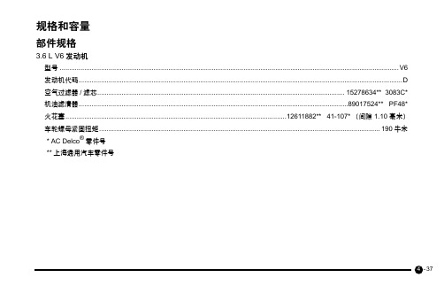
2009款别克昂科雷发动机电气部分原厂维修手册(英文)Engine Electrical 9-1EngineEngine ElectricalSpecicationsSIE-ID 2085636 Owner csmith01 LMD 25-mar-2008 LMB csmith01Fastener TighteningSpecicationsSpecicationApplication Metric EnglishAccessory Wiring Junction Block Nut 22 N·m 16 lb ftAir Conditioning Liquid Line Clamp Bolt 9 N·m 80 lb inBattery Cover Screw 16 N·m 14 lb inBattery Hold Down Bolt 25 N·m 18 lb ftBattery Negative Cable Extension Cable to Cylinder Head Bolt 58 N·m 43 lb ftBattery Negative Cable Extension Cable to Left Wheelhouse Panel 58 N·m 43 lb ftUpper Reinforcement BoltBattery Positive Junction Block Cable to Generator Nut22 N·m 16 lb ftCoolant Recovery Reservoir Bolt 5 N·m 44 lb inGenerator Bolt 50 N·m 37 lb ftNegative Battery Cable Ground Bolt 25 N·m 18 lb ftNegative Battery Cable Terminal Nut 9 N·m 80 lb inPositive Battery Cable Terminal Nut 9 N·m 80 lb inStarter Bolt 50 N·m 37 lb ftStarter Heat Shield Bolt 7 N·m 62 lb inStarter Solenoid BAT Terminal Nut 25 N·m 18 lb ftSIE-ID 1876548 Owner jgrant01 LMD 07-dec-2006 LMB garciaBattery UsageApplication SpecicationCold Cranking 730 AAmperage CCAAmp Hours 70 AHReserve Capacity 100 MinutesReplacement Model48-7YRNumberSIE-ID 1876549 Owner jgrant01 LMD 07-dec-2006 LMB garciaGenerator UsageApplication SpecicationGenerator Model SC3Rated Output 170 AmpsLoad Test Output 119 Amps2009 - Acadia Enclave OUTLOOK Traverse VIN RV Service Manual June 24 20089-2 Engine ElectricalSchematic and Routing Diagrams2009 - Acadia Enclave OUTLOOK Traverse VIN RV Service Manual June 24 2008Engine Electrical 9-393877282-ram-8 2D M L 023780 2D I - O I S 1 3778 0 2D I -E ISg n i t r a t Ss c i t a m e h c S gn i g r a h C d n a gnitratS2009 - Acadia Enclave OUTLOOK Traverse VIN RV Service Manual June 24 20089-4 Engine Electrical24877280 2 - r a m - 8 2DM L12378 0 2DI - O I S 1 3 778 02D I -E I Sg ni g r a h Cs c i ta m e h c S g n i g ra h C d n a g n i t ratS2009 - Acadia Enclave OUTLOOK Traverse VIN RV Service Manual June 24 2008Engine Electrical 9-5Diagnostic Information and ProceduresDiagnostic Starting Point - EngineElectricalSIE-ID 1947400 Owner jkassi01 LMD 30-mar-2007 LMB jgrant01Begin the system diagnosis with Diagnostic System Check - Vehicle on page 6-60 The Diagnostic System Check – Vehicle will provide the following information The identication of the control modules whichcommand the systemThe ability of the control modules to communicate through the serial data circuitThe identication of any stored diagnostic trouble codes DTCs and their statusThe use of the Diagnostic System Check – Vehiclewill identify the correct procedure for diagnosingthe system and where the procedure is located2009 - Acadia Enclave OUTLOOK Traverse VIN RV Service Manual June24 20089-6 Engine ElectricalDTC B1325SIE-ID 1877934 Owner jgrant01 LMD 22-feb-2008 LMB jgrant01Diagnostic Instructions DTC DescriptorsPerform the Diagnostic System Check - Vehicle DTC B1325 03 Device Power Circuit Voltage Belowon page 6-60 prior to using this diagnostic ThresholdprocedureDTC B1325 07 Device Power Circuit Voltage AboveReview Strategy Based Diagnosis on page 6-57 Thresholdfor an overview of the diagnostic approach DTC B1325 4A Device Power Circuit ChecksumDiagnostic Procedure Instructions on page 6-58 Error – HUDIPCprovides an overview of each diagnosticcategoryDiagnostic Fault InformationShort to OpenHigh Short to SignalCircuit Ground Resistance Voltage PerformanceB1325 03B1325 03BB1325 4AB1325 4AB1325 03Ground B1325 4ACircuitSystem Description B1325 4AThe following control modules monitor the battery The HUD or IPC failed the power on checksum testvoltage through the battery positive B voltageeither due to low voltage or corrupted memorycircuitsHead-up display HUD Action Taken When the DTC SetsInstrument panel cluster IPC The control module immediately disablesPassenger presence system PPS all outputs when an out of range voltage conditionhas been detected with the exception of serialRadiodata which is disabled after a 3 minute delayUltrasonic parking aid UPAThe setting of other DTCs is inhibitedIf any of the control modules listed detect that thebattery voltage is out of range it will set DTC B1325 Conditions for Clearing the DTCConditions for Running the DTC The DTC passes when the malfunction is no longerpresentThe ignition is ONThe battery voltage supplied to the control module Diagnostic Aidsis in the range of 7–26 voltsA high or low voltage value in multiple modulesindicates a concern in the charging systemConditions for Setting the DTCOvercharging with a battery charger or jumpB1325 03 starting can cause this DTC to setThe control module detects that the system voltage isless than 9 volts for 5 seconds Reference InformationB1325 07 Schematic ReferenceThe control module detects that the system voltage is Head Up Display Schematics on page 8-7greater than 18 volts for 5 seconds Instrument Cluster Schematics on page 8-3SIR Schematics on page 13-3RadioNavigation System Schematics on page 8-3Object Detection Schematics on page 13-2Starting and Charging Schematics on page 9-3Connector End View ReferenceComponent Connector End Views on page 11-211Description and OperationCharging System Description and Operation onpage 9-672009 - Acadia Enclave OUTLOOK Traverse VIN RV Service Manual June 242008Engine Electrical 9-7Electrical Information Reference Repair InstructionsCircuit Testing on page 11-456 Perform the Diagnostic Repair Verication onConnector Repairs on page 11-478 page 6-86 after completing the diagnostic procedureTesting for Intermittent Conditions and Poor Control Module References on page 6-1 for theConnections on page 11-460 appropriate module replacement setup andWiring Repairs on page 11-465 programmingScan Tool ReferenceControl Module References on page 6-1 for scan toolinformationCircuitSystem Testing1 Engine running accessories OFF measure andrecord the battery voltage at the battery terminals The voltage should be between 126 and150 voltsIf not within the specied range refer toCharging System Test Acadia or Enclave onpage 9-39 or Charging SystemTest OUTLOOK on page 9-402 Ignition OFF disconnect the harness connectorsat the appropriate module3 Ignition OFF and scan tool disconnected openand close the driver door and wait 1 minuteTest for less than 5 ohms between the groundcircuits listed below and groundTerminal 2 IPCTerminal 4 HUDTerminal D PPSTerminal 5 X1 Radio UQGTerminal 8 X1 Radio U42UQFUQAUQSTerminal 7 X1 UPAIf greater than the specied range test theground circuit for an openhigh resistance4 Verify that a test lamp illuminates between the Bcircuit terminals listed below and groundTerminal 1 IPCTerminal 6 HUDTerminal A PPSTerminal 1 X1 UPA Radio U42UQFUQGTerminal 4 X1 Radio UQAUQSIf the test lamp does not illuminate test the B circuit for a short to ground or anopenhigh resistance5 If all circuits test normal replace the appropriate control module2009 - Acadia Enclave OUTLOOK Traverse VIN RV Service Manual June24 20089-8 Engine ElectricalDTC B1424SIE-ID 1876361 Owner jgrant01 LMD 22-feb-2008 LMB jgrant01Diagnostic Instructions DTC DescriptorPerform the Diagnostic System Check - Vehicle DTC B1424 00 Device Voltage Low – Thefton page 6-60 prior to using this diagnostic Deterrent ModuleprocedureReview Strategy Based Diagnosis on page 6-57 Diagnostic Fault Informationfor an overview of the diagnostic approachDiagnostic Procedure Instructions on page 6-58provides an overview of each diagnosticcategoryShort to OpenHigh Short to SignalCircuit Ground Resistance Voltage PerformanceB B1424 00B1424 00GroundB1424 00CircuitSystem DescriptionDiagnostic AidsThe theft deterrent module TDM monitors the battery A low voltage DTC in multiple modules indicates apositive B voltage available to it If the voltage at concern in the charging systemthe TDM is between 6–9 volts and the voltagebeing reported by a serial data message is greater Reference Informationthan 9 volts then DTC B1424 00 setsSchematic ReferenceConditions for Running the DTC Immobilizer Schematics on page 13-1Connector End View ReferenceThe ignition switch is in Accessory or RunThis diagnostic runs every 100 milliseconds Component Connector End Views on page 11-211Description and OperationConditions for Setting the DTC Immobilizer Description and Operation onVoltage at the TDM B circuit is between 6–page 13-239 volts Charging System Description and Operation onReported battery voltage received via serial data page 9-67is valid and is greater than 9 volts Electrical Information ReferenceThe above conditions have been met for Circuit Testing on page 11-4562 seconds Connector Repairs on page 11-478Testing for Intermittent Conditions and PoorAction Taken When the DTC Sets Connections on page 11-460The security indicator turns ON Wiring Repairs on page 11-465The driver information center DIC displays the Scan Tool ReferenceSERVICE THEFT DETERRENT SYSTEMControl Module References on page 6-1 for scan toolmessageinformationConditions for Clearing the DTC CircuitSystem TestingThis DTC passes when the battery voltage at the 1Engine running accessories OFF measure andTDM is greater than 9 volts or if the voltage record the battery voltage at the battery terminalsreported by serial data is less than 9 volts The voltage should be between 126 and150 voltsA history DTC clears after 100 consecutiveignition cycles if no failures are reported by this If not within the specied range refer todiagnostic Charging System Test Acadia or Enclave onpage 9-39 or Charging SystemTest OUTLOOK on page 9-402 Ignition OFF disconnect the harness connector atthe TDM3 Ignition OFF and scan tool disconnected openand close the driver door and wait 1 minuteTest for less than 5 ohms between the groundcircuit terminal 3 and ground2009 - Acadia Enclave OUTLOOK Traverse VIN RV Service Manual June 24 2008Engine Electrical 9-9If greater than the specied range test theground circuit for an openhigh resistance4 Verify that a test lamp illuminates between theB circuit terminal 1 and groundIf the test lamp does not illuminate test theB circuit for a short to ground or anopenhigh resistance5 If all circuits test normal replace the TDMRepair InstructionsPerform the Diagnostic Repair Verication onpage 6-86 after completing the diagnostic procedureControl Module References on page 6-1 for TDMreplacement setup and programming2009 - Acadia Enclave OUTLOOK Traverse VIN RV Service Manual June 24 20089-10 Engine ElectricalDTC B1516SIE-ID 1875993 Owner jgrant01 LMD 22-may-2008 LMB jgrant01Diagnostic Instructions DTC DescriptorsPerform the Diagnostic System Check - Vehicle DTC B1516 08 Battery Current Sensor Performanceon page 6-60 prior to using this diagnostic Signal InvalidprocedureReview Strategy Based Diagnosis on page 6-57 DTC B1516 66 Battery Current Sensor Performancefor an overview of the diagnostic approach Wrong Mounting PositionDiagnostic Procedure Instructions on page 6-58provides an overview of each diagnostic Diagnostic Fault InformationcategoryShort to OpenHigh Short to SignalCircuit Ground Resistance Voltage Performance5 V Reference B1516 08B1516 08B1516 08Signal B1516 08B1516 08 B1516 08 B1516 66Low Reference B1516 08Typical Scan Tool DataBatteryCurrentCircuit Short toGround Open Short to VoltageOperating Conditions Ignition ON engine OFF Headlamps HVAC and allaccessories OFFParameter Normal Range 3 amps to 25 amps5 V Reference 599amps 599 amps 62 ampsSignal 599amps 599 amps 599 ampsLow Reference 599 ampsCircuitSystem Description B1516 66The battery current sensor is a 3-wire hall effect The BCM is awakecurrent sensor The body control module BCM The engine is OFFsupplies 5 V and ground to the battery current sensorThe battery current sensor measures the amount of Conditions for Setting the DTCcurrent owing to or from the battery and suppliesa pulse width modulation PWM signal to the BCM B1516 08The signal has a normal range of 4–96 percent The battery current signal is less than 4 percent orduty cycle The BCM also monitors the current polarity greater than 96 percent duty cycle for 2 minutesto detect if the sensor is installed backwards or onthe wrong cable The current should be negative when B1516 66the engine is OFF if the sensor is installed correctly Thebattery current polarity is positive for 2 minutesConditions for Running the DTC Action Taken When the DTC SetsB1516 08 The regulated voltage control RVC is disabledThe BCM is awake。