APC240F水表无线抄表模块, 抄表成功率超过99%
惠普240 G9 14英寸笔记本电脑说明书
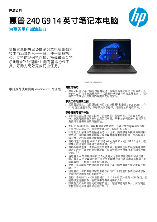
产品说明惠普 240 G9 14 英寸笔记本电脑为商务用户加油助力价格实惠的惠普 240 笔记本电脑集强大技术与流线外形于一身,便于随身携带,支持时刻保持连接。
搭载最新英特尔®酷睿™处理器并配有基本协作工具,可助力高效完成商业任务。
*产品图像可能与实物有所差别惠普推荐使用商用 Windows 11 专业版精致而轻巧惠普 240 笔记本电脑采用轻薄设计,能够有效满足移动办公需求。
可选的 400 尼特全高清显示屏 采用窄边框设计并具有高屏占比 ,可为高效工作或显示流媒体内容提供充足的空间。
兼具工作与娱乐功能采用最新技术,包括强劲的英特尔® 处理器 和最高 32 GB DDR4 内存、可选双通道内存、双存储及固态存储,可助您从容完成项目。
获得清晰的视听体验支持您与团队保持密切联系,无论他们在隔壁房间,还是数英里之外。
高清降噪摄像头能够让您风采毕现,基于 AI 的降噪软件和双阵列麦克风可提供高品质音频体验。
大尺寸 14 英寸显示屏具有 400 尼特亮度、低蓝光特性和较高屏占比,并采用窄边框设计,可提高整体体验,助力轻松工作。
针对低光照条件下的视频通话进行了优化。
高清摄像头提供清晰的视觉效果,临时降噪功能缓解了视觉噪音和像素化的影响,从而提高了清晰度,让您能够捕捉所有细节。
借助可选千兆速度 Wi-Fi 6 和可选 WLAN 802.11ac/蓝牙® 5.0 组合,在密集无线环境中快速建立可靠连接。
借助双存储选件,收获两全其美的成果。
利用高速固态硬盘快速启动和访问应用,并使用高容量硬盘,尽享专为数字媒体打造的超大存储空间。
通过基于 AI 的降噪软件和双阵列麦克风尽享高效在线呼叫和会议体验。
基于 AI 的降噪软件将行业领先的噪音过滤技术应用到所有输入和输出音频中,有助于改善协作体验。
使用主机匹配指纹传感器保护您的笔记本电脑免遭硬件和恶意软件威胁。
轻松捕获、保护并存储您的生物识别资产,同时主机系统可帮助您保护指纹数据的完整性和隐私性。
GOIP中文说明书

HP t240 Thin Client 产品说明书

HP t240 Thin ClientFront View Image Rear View ImageFRONT BACK1. Power button 1. VGA analog video output2. 1 x USB-A 2.0 Type A 2. HDMI digital video output3. 1 x USB 3.1 Gen 1 port 3. 2 x USB-A 2.0 Type A4. 1 x Microphone audio port 4. RJ45 Gigabit Ethernet interface5. 1 x 3.5 mm headphone audio port 5. 15V DC power inputBOTTOM 6. Cable lock slotVESA mounting points located underneath the system’srubber foot padsAT A GLANCE•Intel® Atom® Processor x5-Z8350; 1.44 – 1.92 GHz quad-core processor•Embedded DDR3L single-channel SDRAM system memoryo HP ThinPro models configured with 2 GB•Embedded Multi Media Cardo HP ThinPro models configured with 8 GB• 1 x VGA, 1 x HDMI 1.4b video outputs supporting up to (1920 x 1080) resolutions.•Gigabit Ethernet (GbE) network connection supported via an integrated Realtek GbE NIC module and presented with an RJ45 connector on the rear I/O panel•Optional Wi-Fi® including antennas integrated internally in the chassis1.•USB ports located on the front and back panels, including one USB-A 3.1 Gen 1 Type A port and three USB 2.0 Type A ports • 3.5 mm headphone audio port on front panel that will support a headphone or an external speaker system• 3.5 mm microphone audio port on front panel that will support a microphone•Integrated VESA 75:100 mounting system; the four threaded holes are conveniently located under the unit’s rubber foot pads•The security features include a system UEFI designed to address NIST SP 800-147 guidelines and cable lock slot•ENERGY STAR® certified.•Post-consumer recycled plastics content greater than 25% total unit plastics (by weight)•Low halogen2material content1 Wireless access point and Internet access is required; availability of public wireless access points is limited2 This product is low halogen except for power cords, cables and peripherals; service parts obtained aftermarket may not be low halogen WarrantyHP Customer Support: limited three-year hardware limited warranty in most regions; HP Care Packs are optional extended service contracts that go beyond your standard limited warranties; for more details visit /go/cpcOPERATING SYSTEMSHP ThinPro, including HP Smart Zero Core (Not default setting and customer need to configure)GRAPHICSNumber of displays supported: One or two displays.NOTE: a maximum of two displays are supported.Video outputs: 1 x HDMI port 1 x VGA portNOTE:Dual displays are supported using the following video output combinations:•HDMI + VGAVideo Resolution Support MatrixMEMORYType: Single channel DDR3L SDRAM (Soldered down)Data Transfer Rate (speed): up to 1,600 MT/sPeak Transfer Rate (bandwith): 12,800 MB/sNumber of slots: 0 slots; memory is embeddedMemory Capacity: 2 GB on ThinPro modelsReserved for graphics: Max 2 GBNOTE:The system’s Graphics Processing Unit (GPU) uses part of total system memory. System memory dedicated to graphics performance is not available for use by other programsUEFI (Unified Extensible Firmware Interface)•UEFI Specification Revision: 2.3.1•Meets requirements for Common Criteria, an independent third-party certification of trustworthiness•Meets requirements for FIPS 140-2, a standard for cryptographic integrity•Designed to address NIST SP800-147 guidelinesSTORAGEType: eMMc 4.51Number of sockets: 0 slots; flash storage is embeddedStorage Capacity: 8 GB on HP ThinPro modelsINPUT/OUTPUTUSB ports: 1 x USB 3.1 Gen 1 Type A front port and 1 x USB 2.0 Type A front port2 x USB 2.0 Type A rear portsVideo outputs*: 1 x VGA1 x HDMI 1.4bOther: 1 x RJ45 GbE interface1 x 3.5mm headphone port 1 x 3.5 mm microphone portNOTE: 2 video outputs can be used simultaneouslyAUDIO/VIDEOAudio: 3.5 mm headphone audio port supporting headphones or and external speaker 3.5 mm microphone audio port on front panel that will support a microphone Audio CODECs include MP3, HEAAC, WMA 7/8/9Includes hardware acceleration supportVideo: MPEG-4 part 4 (HP.263)MPEG-4 part 10 (H.264), Advanced Video Coding (AVC) WMV 7/8/9VC1Includes hardware acceleration supportHARDWARE SECURITY•Security lock support (slim cable lock sold separately) NETWORKINGWired networks: Realtek Gigabit Ethernet (GbE) Wake on LANPXE (UEFI only)TCP/IP with DNS DHCPWireless networks: AzureWave CM 276NF( Dual band 802.11 a/b/g/n/ac wireless) NGFF moduleNOTE: Wireless access point and Internet access required. Availability of public wireless access point may be limited. Wireless features, performance and support may vary depending on environmental variables such as placement, settings and firmware of the access point. Contact your wireless vendor for support.WEIGHTS & DIMENSIONSW x D x H 110 x 110 x 30 mmVolume 0.3literSystem Weight 276 g (0.61 lb.)Shipping Weight 1690 g (3.73 lb.)NOTE: All measurements are approximate; the addition of optional modules will increase the weightPOWER SUPPLY15W external power adapterWorldwide auto-sensing 100-240 VAC, 50-60 HzEnergy saving automatic power-downSurge tolerantAGENCY COMPLIANCEEnvironmental Stewardship: ENERGY STAR®, EPEAT®, ROHS, ERP, CECP, HP GSE, etc. Product Safety: IEC60950-1, EN60950-1, UL60950-1 GS, BIS & CCC) Electromagnetic Compliance (EMC): FCC, EN55032 Class B, EN55024 & FCCENVIRONMENTALOperating Temperature Range: 50° to 104° F (10° to 40° C)Non-operating Temperature Range: -22° to 140° F (-30° to 60° C)Humidity: Condensing: 20% to 80% Non-condensing: 10% to 90%NOTE: Specifications are at sea level with altitude derating of 1° C/300m (1.8° F/1000ft) to a maximum of 3 Km (10,000 ft), with no direct, sustained sunlight. Upper limit may be limited by the type and number of options installed.Eco-Label Certifications & declarations This product has received or is in the process of being certified to the following approvals and may be labeled with one or more of these marks:•ENERGY STAR®•EPEAT® Silver registered in the United States. See for registration status in your country.•IT ECO declarationEnergy Consumption(in accordance with US ENERGY STAR®115 V ac, 60 Hz 230 V ac, 50 Hz 100 V ac, 50 Hztest method)Normal Operation (Short idle) 2.90 W 3.00 W 2.90 W Normal Operation (Long idle) 2.40 W 2.60 W 2.40 WSleep 2.40 W 2.50 W 2.30 WOff 0.30 W 0.30 W 0.30 WHeat Dissipation* 115 V ac, 60 Hz 230 V ac, 50 Hz 100 V ac, 50 Hz Normal Operation (Short idle) 10 BTU/hr 10 BTU/hr 10 BTU/hr Normal Operation (Long idle) 8 BTU/hr 9 BTU/hr 8 BTU/hrSleep 8 BTU/hr 9 BTU/hr 8 BTU/hrOff 1 BTU/hr 1 BTU/hr 1 BTU/hrNOTE:Heat dissipation is calculated based on the measured watts, assuming the servicelevel is attained for one hour.Additional Information •This product is in compliance with the Restrictions of Hazardous Substances(RoHS) directive -2011/65/EC.•This HP product is designed to comply with the Waste Electrical and ElectronicEquipment (WEEE) Directive – 2002/96/EC.•This product is in compliance with California Proposition 65 (State of California;Safe Drinking Water and Toxic Enforcement Act of 1986).•This product is in compliance with the IEEE 1680 (EPEAT®) standard at the Silverlevel, see •Plastics parts weighing over 25 grams used in the product are marked per ISO11469 and ISO1043.•This product contains 1.75 % post-consumer recycled plastic (by wt.)•This product is 91.4 % recycle-able when properly disposed of at end of life.Packaging Materials External: PAPER/Paperboard 427 gInternal: PLASTIC/Polyethylene high density - HDPE 2 gPLASTIC/LDPE 16 gRoHS Compliance HP Inc. is committed to compliance with all applicable environmental laws andregulations, including the European Union Restriction of Hazardous Substances (RoHS)Directive. HP’s goal is to exceed compliance obligations by meeting the requirements ofthe RoHS Directive on a worldwide basis. By July 1, 2006, RoHS substances will bevirtually eliminated (virtually = to levels below legal limits) for all HP electronic productssubject to the RoHS Directive, except where it is widely recognized that there is notechnically feasible alternative (as indicated by an exemption under the EU RoHSDirective).Material Usage This product does not contain any of the following substances in excess of regulatorylimits (refer to the HP General Specification for the Environment at/hpinfo/globalcitizenship/environment/supplychain/gen_specifications.html):•Asbestos•Certain Azo Colorants•Certain Brominated Flame Retardants – may not be used as flame retardants inplastics•Cadmium•Chlorinated Hydrocarbons•Chlorinated Paraffins•Formaldehyde•Halogenated Diphenyl Methanes•Lead carbonates and sulfates•Lead and Lead compounds•Mercuric Oxide Batteries•Nickel – finishes must not be used on the external surface designed to befrequently handled or carried by the user.•Ozone Depleting Substances•Polybrominated Biphenyls (PBBs)•Polybrominated Biphenyl Ethers (PBBEs)•Polybrominated Biphenyl Oxides (PBBOs)•Polychlorinated Biphenyl (PCB)•Polychlorinated Terphenyls (PCT)•Polyvinyl Chloride (PVC) – except for wires and cables, and certain retailpackaging has been voluntarily removed from most applications.•Radioactive Substances•Tributyl Tin (TBT), Triphenyl Tin (TPT), Tributyl Tin Oxide (TBTO)Packaging HP follows these guidelines to decrease the environmental impact of product packaging:•Eliminate the use of heavy metals such as lead, chromium, mercury andcadmium in packaging materials.•Eliminate the use of ozone-depleting substances (ODS) in packaging materials.•Design packaging materials for ease of disassembly.•Maximize the use of post-consumer recycled content materials in packagingmaterials.•Use readily recyclable packaging materials such as paper and corrugatedmaterials.•Reduce size and weight of packages to improve transportation fuel efficiency.•Plastic packaging materials are marked according to ISO 11469 and DIN 6120standards.End-of-life Management and Recycling HP Inc. offers end-of-life HP product return and recycling programs in many geographicareas. To recycle your product, please go to: /go/reuse-recycle orcontact your nearest HP sales office. Products returned to HP will be recycled, recoveredor disposed of in a responsible manner.The EU WEEE directive (2002/95/EC) requires manufacturers to provide treatmentinformation for each product type for use by treatment facilities. This information(product disassembly instructions) is posted on the HP Inc. web site at:/go/recyclers. These instructions may be used by recyclers and otherWEEE treatment facilities as well as HP OEM customers who integrate and re-sell HPequipment.Technical specificationsHP, Inc. Corporate EnvironmentalFor more information about HP’s commitment to the environment:InformationGlobal Citizenship Report/hpinfo/globalcitizenship/gcreport/index.htmlEco-label certifications/hpinfo/globalcitizenship/environment/productdesign/ecolabels.htmlISO 14001 certificates:/V2/GetDocument.aspx?docname=c04755842and/hpinfo/globalcitizenship/environment/pdf/cert.pdfSummary of Changes© 2019 HP Development Company, L.P. The information contained herein is subject to change without notice. The only warranties for HP products and services are set forth in the express limited warranty statements accompanying such products and services. Nothing herein should be construed as constituting an additional warranty. HP shall not be liable for technical or editorial errors or omissions contained herein. AMD and Radeon are trademarks of Advanced Micro Devices, Inc. DisplayPort™ and the DisplayPort™ logo are trademarks owned by the Video Electronics Standards Association (VESA®) in the United States and other countries. Amazon Web Services, the “Powered by Amazon Web Services” logo, and Amazon WorkSpaces are trademark s of , Inc. or its affiliates in the United States and/or other countries. Bluetooth® is a trademark owned by its proprietor and used by HP Inc. under license. ENERGY STAR is a registered trademark owned by the U.S. Environmental Protection Agency. Linux® is the registered trademark of Linus Torvalds in the U.S. and other countries. Microsoft and Windows are either registered trademarks or trademarks of Microsoft Corporation in the United States and/or other countries. Intel® is a trademark of Intel Corporation in the U.S and other countries. VMware Horizon and VMware Horizon View are registered trademarks or trademarks of VMware, Inc. in the United States and/or other jurisdictions. Citrix and Citrix Workspace are trademarks of Citrix Systems, Inc. and/or one more of its subsidiaries, and may be registered in the United States Patent and Trademark Office and in other countries.。
锐捷NBR路由器用户手册

3.3
安装电源线及地线................................................................................................................... 10
3.4
连接控制台 .............................................................................................................................. 10
第七章 路由器的维护 介绍了如何对路由器进行主体软件、BOOTROM 软件进行升级。
感谢您选择锐捷 NBR 系列路由器!
说明:
该安装手册只介绍如何安装锐捷 NBR 系列路由器,要使用路由器还需要进行具体的 配置,关于如何配置路由器的详细信息,请参考相关部分的配置参考。 在本手册中,锐捷 RG-NBRxxx 系列路由器简称为锐捷 NBRxxx 系列路由器。 详细的说明和配置以随机附带的光盘为准,如果因为时间而有改变,恕不另行通知。
2.2.5 防雷击要求......................................................................................................................... 7
2.2.6 检查安装装置..................................................................................................................... 7
最小最省电的433MHz 470MHz无线模块

APC240超低功耗433MHz470MHz无线数传模块DVER1.4APC240模块是高度集成的超低功耗无线数据传输模块,其嵌入高速单片机和高性能射频芯片。
创新的采用高效的循环交织纠检错编码,抗干扰和灵敏度都大大提高,APC240模块提供了多个频道的选择,可在线修改串口速率,发射功率,射频速率等各种参数。
(APC240B是APC240的邮票孔超小定制款,性能相同但尺寸更小,适合嵌入贴片于用户PCB板上)APC240模块可在2.1-3.6V电压范围内工作,在接收状态仅仅消3.2mA,有四种工作模式。
在1SEC周期轮询唤醒省电模式(Polling mode)下,接收仅仅消耗不到20uA,一节3.6V/3.6A的锂亚电池可工作10年以上。
APC240APC240B应用:●无线水气热表●无线传感器●自动化数据采集●工业遥控、遥测●楼宇小区自动化与安防●机器人控制●电力高压高温监测●气象,遥感特点:●400米传输距离(5000bps)●频率433MHz或470MHz●多频道可设,FSK调制方式●零等待休眠至唤醒时间●四种工作模式灵活切换●高效的循环交织纠错编码●超低功耗,电流极低,待机仅电流1.5uA●双256bytes数据缓冲区●内置看门狗,保证长期可靠运行APC240模块是新一代的多通道嵌入式无线数传模块,可设置多个频道,步进为1KHz,发射功率最大10mW,体积32.1mm x18.3mm x7.0mm,很方便客户嵌入系统之内,APC240模块具有极低的功耗,非常适合于电池供电系统。
APC240模块创新的采用了高效的循环交织纠检错编码,其编码增益高达近3dBm,纠错能力和编码效率均达到业内的领先水平,远远高与一般的前向纠错编码,抗突发干扰和灵敏度都较大的改善。
同时编码也包含可靠检错能力,能够自动滤除错误及虚假信息,真正实现了透明的连接。
所以APC240模块特别适合与在工业领域等强干扰的恶劣环境中使用。
Philips AX2400 AX2401 AX2420 可移动CD播放器用户手册说明书
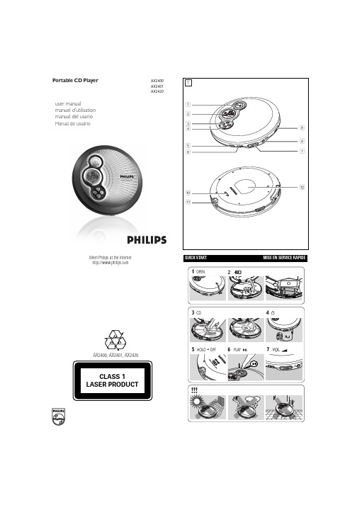
QUICK STARTMISE EN SERVICE RAPIDEMeet Philips at the Internet user manualmanuel d’utilisation manual del usarioManual do usuárioAX2400, AX2401,AX2420Portable CD PlayerAX2400AX2401AX2420EnglishCONTROLS / POWER SUPPLY12;......................switches the player on, starts or pauses CD play 2............................display39.........................stops CD play, clears a program or switches the player off ∞.......................skips and searches CD tracks backwards §.......................skips and searches CD tracks forwards4DBB.....................switches the bass enhancement on and off. This button alsoswitches acoustic feedback (the beep) on/off when it is pressed for more than 2 seconds5PROG...................programs tracks and reviews the program6MODE/ESP..........selects the different playing possibilities: SHUFFLE ,SHUFFLE REPEAT ALL , REPEAT , REPEAT ALL and SCAN ,switch ESP on/off7VOLUME +/-......adjust the volume8p /LINE OUT........3.5 mm headphone socket, socket to connect the player toanother audio input of an additional appliance.9OPEN ç............opens the CD lid 0HOLD...................locks all buttonsRESUME.............stores the last position of a CD track played OFF......................switches RESUME and HOLD off !4.5V DC...............socket for external power supply @............................type platePOWER SUPPLY / GENERAL INFORMATIONUse only the AY 3162 adapter (4.5 V / 300 mA directmay damage the player.1adapter’s voltage.2Connect the power adapter to the 4.5V DC socket of the player and to the wall socket.Note: Always disconnect the adapter when you are not using it.Environmental information•All redundant packing material has been omitted. We have done our utmost to make the packaging easily separable into two materials: cardboard (box) and polyethylene (bags, protective foam sheet).•Your set consists of materials which can be recycled if disassembled by a specialized company. Please observe the local regulations regarding the disposal of packing materials, exhausted batteries and old equipment.Batteries contain chemical substances, so they should be disposed of properly.IMPORTANT!Hearing safety: Do not play your headphones at a high volume. Hearing experts advise that continuous use at high volume can permanently damage your hearing.Traffic safety: Do not use headphones while driving a vehicle. It may create a hazard and it is illegal in many countries. Even if your headphones are an open-air type designed to let you hear outside sounds, do not turn up the volume so high that you cannot hear what is going on around you.GENERAL INFORMATION / CD PLAY4Turn down the volume and connect the cassette adapter plug to p /LINE OUT on the set.5Carefully insert the cassette adapter into the car radio’s cassette compartment.6Make sure the cord does not hinder your driving.7Decease the volume on the set, if necessary. Start playback on the set and adjust the sound with the car radio controls.•Always remove the voltage converter from the cigarette lighter socket when the set is not in use.Note: If your car radio has a LINE IN socket , it is better to use it for thecar radio connection instead of the cassette adapter. Connect the signal lead to this LINE IN socket and to p /LINE OUT on the set.CD PLAY / FEATURESBass adjustment•Press DBB to switch the bass enhancement on or offy appears if the bass enhancement isactivated.DBB2CD onto the hub. 3Close the player by pressing the lid down.4Press 2;y time are displayed.•You can pause playback by pressing 2;.y flashing.•You can continue playback by pressing 2;5Press 9 to stop playback.y time of the CD are displayed.6Press 9 again to switch the player off.•hub gently while lifting the CD.switch off after a while to save energy.Selecting a track during playback•Briefly press ∞ or §the current, previous or next track.y the track’s number is displayed.Briefly press ∞ or §the desired track. The track number is displayed.Press 2;to start CD play.y Playback starts with the selected track.Keep ∞ or §pressed to find a particular passage in a backward or forward direction.y Searching starts while playback continues at lowvolume. After 2 seconds the search speeds up.Release the button when you reach the desired passage.y Playback continues from this position.– If the player is in SCAN mode (see MODE chapter), searching is notpossible.– In shuffle, shuffle repeat all or repeat mode (see MODE chapter), or while playing a program, searching is only possible within the particular track.•To deactivate RESUME, switch the slider to OFF.random order until all of them have been played once.y SHUFFLE REPEAT ALL : All tracks of the CDare played repeatedly in random order.y REPEAT : The current track is played repeatedly.y REPEAT ALL : The entire CD is played repeatedly.y SCAN : The first 10 seconds of each of theremaining tracks are played in sequence.2Playback starts in the chosen mode after 2 seconds.•To return to normal playback, press MODE repeatedly until the display shows no active modes.ESPWith a conventional portable CD-player you might have experienced that the music stopped e.g. when you were jogging. The E lectronic S kip P rotectionprevents loss of sound caused by light vibrations and shocks. Continuous playback is ensured. However ESP does not prevent playback interruptions during vigorous running. It also does not protect the unit against any damage caused by dropping!In this set ESP is default ON. It is possible to set ESP off.•Press MODE/ESP for more than 3 seconds.y ESP disappears.•Press MODE/ESP again for more than 3 seconds.y ESP is displayed.ESP on ➟ESP off ➟ESP oncorrectly, that the contact pins are clean.•Your adapter connection may be loose. Connect it securely.•For in-car use, check that the car ignition is on. Also check player’s batteries.The indication NO dISC is displayed•Check that the CD is clean and correctly inserted (label-side upward).•If your lens has steamed up, wait a few minutes for this to clear.The indication NF dISC is displayed•CD-RW (CD-R) was not recorded properly. Use FINALIZE on your CD-recorder.The indication HOLD is on and/or there is no reaction to controls •If HOLD is activated, then deactivate it.•Electrostatic discharge. Disconnect power or remove batteries for a few seconds.The CD skips tracks•The CD is damaged or dirty. Replace or clean the CD.•RESUME, SHUFFLE or PROGRAM is active. Switch off whichever is on.No sound or bad sound quality.•PAUSE might be active. Press 2;.•Loose, wrong or dirty connections. Check and clean connections.•Volume might not be appropriately adjusted. Adjust the volume.•Strong magnetic fields. Check player’s position and connections. Also keep away from active mobile phones.•For in-car use,check that the cassette adapter is inserted correctly, that the car cassette player’s playback direction is correct (press autoreverse to change),and that the cigarette lighter jack is clean. Allow time for temperature change.Thank-you for purchasing this quality Philips product.Philips New Zealand Ltd guarantees this product against defective components and faulty workmanship for a period of 12months. Any defect in materials or workmanship occurring within 12 months from the date of purchase subject to the following conditions will be rectified free of charge by the retailer from whom this product was purchased.Conditions1. The product must have been purchased in New Zealand. As proof of purchase,retain the original sales docket indicating the date of purchase.2. The guarantee applies only to faults caused by defective components, or faulty workmanship on the part of the manufacturer.3. The guarantee does not cover failures caused by misuse, neglect, normal wear and tear, accidental breakage, use on the incorrect voltage, use contrary to operating instructions, or unauthorised modification to the product or repair by an unauthorised technician.4. Reasonable evidence (in the form of a sales docket) must be supplied to indi-cate that the product was purchased no more than 12 months prior to the date of your claim.5. In the event of a failure, Philips shall be under no liability for any injury, or any loss or damage caused to property or products other than the product under guarantee.This guarantee does not prejudice your rights under common law and statute, and is in addition to the normal responsibilities of the retailer and Philips.These warranty conditions are valid for the following consumer electronics products: Colour Televisions, Video Cassette Recorders, CD Players and Recorders, DVD Players and Recorders, Audio Systems and Portable Audio.The benefits given to the purchaser by this warranty are in addition to all other rights and remedies which the purchaser has in respect of the product under the Trade Practices Act or other Commonwealth or State Law.Philips Consumer Electronics warrants its products to the purchaser as follows and subject to the stated conditions.3 YEARS free Repair ServiceColour Televisions, CD Players and Recorders, DVD Players and Recorders and Audio Systems.3 YEARS free Replacement – at your RetailerAll Portable Audio products and all Video Cassette recorders (VCR’s) only.Conditions of Repair Warranty1.All claims for warranty service should be made to your nearest Philips Authorised Service Centre. Reasonable evidence of date of purchase must be provided.2.This warranty extends only to defects in material or workmanship occurring under nor-mal use of the product when operated in accordance with the instructions.3.This warranty applies for original purchase only. It is not transferable if sold.4.Home service within the normal service area of one of our Authorised Service Centres will only be provided for television receivers with screen size 48 cm and above. All other products are to be taken or sent to the workshop of your nearest Authorised Service Centre (at Consumer’s expense).5.This Manufacturers Warranty is limited to 3months for above listed Consumer Electronics products if used in commercial applications.6.Philips may, at its discretion choose to replace rather than repair any product covered by this warranty.7.This Manufacturers Warranty is neither transferable nor valid in countries other than Australia.This warranty does not cover:a)Mileage or travelling time, pickup or delivery, installations and cost of insurance.b)Mileage or travel outside the normal service area covered by selected Authorised Service Centre.c)Service costs arising from failure to correctly adjust the controls of the product or to observe the instructions, or inspections that reveal that the product is in normal working order.Adelaide Launceston Brisbane Melbourne Canberra Newcastle Geelong Perth Gold Coast Sydney Hobart Wollongong d)Product failures caused by misuse, neglect, accidental breakage, transit damage,inexpert repairs or modification by un-authorised persons, external fires, lightning strikes, floods, vermin infestation or liquid spillage.e)Cleaning of video or audio heads.f)Inadequate receiving antennae.g)Replacement of worn or used batteries or other consumables.h)Consumer products used in commercial applications (This warranty is limited to 3months only).i)Second hand products.The conditions contained in this warranty card replace and override the provision of the Philips World-Wide Guarantee for products purchased in Australia and used in Australia.Philips Authorised Service CentresService is provided through 200 accredited Authorised Service Centres throughout Australia. For direct contact with your nearest recommended Authorised Service Centre in major cities:or to find the location of your nearest recommended Authorised Service Centre outside the above cities please call our National Service telephone number: 1300 361 392Please record the following information for your records and keep in a safe place.Model number:....................................................Serial number:....................................................Date of purchase:....................................................Retailer:....................................................We recommend you retain your purchase receipt to assist in any warranty claim.Philips Consumer Electronicsa division of Philips Electronics Australia Limited ABN 24 008 445 743,Level 2, 65 Epping Road NORTH RYDE NSW 21133 year Warranty valid for all new products purchased after 1st July 2002How to claimShould your Philips product fail within the guarantee period, please return it to the retailer from whom it was purchased. In most cases the retailer will be able to satisfactorily repair or replace the product.However, should the retailer not be able to conclude the matter satisfactorily, or if you have other difficulties claiming under this guarantee, please contact The Guarantee Controller Philips New Zealand Ltd.4P.O. Box 41.021Auckland 3 (09) 84 94 160fax 3 (09) 84 97 858AUSTRALIA-Philips 3 years Manufacturers Warranty for Australia onlyNEW ZEALAND -Guarantee and Service for New Zealand。
PRIMERGY RX2540 M4 2U 机械服务器系统配置器和订单信息指南说明书
5GFX _FPGA FPGA-cards, Graphics-, Grid-cards, GPU and Xeon Co processorsand other graphics optionsHD_cage Base CPU RAM List of content, Instructions for usage of this configurator,abbreviationsdescribes base unit of RX2540 M4Description System Description for easier understandingdescribes rack mount kits and servicesLTO drives & RDX drivePRIMERGY RX2540 M42U Rack Server16414LAN ComponentsFibre Channel ControllerInfiniband Controlleroptical disk drives (DVD, DVD-rw, Blu ray)Storage drives - PCIe SSD - SAS/SATA SSD & HDDOrder code and Infos of Intel® Xeon® Processor Scalable Family CPUs DDR4 System memory (RAM) and memory modesDrive cage and PCIe riser optionsSAS / RAID Controller and componentsChapter 32Folder Cover 79LAN_FC_IB ContentBackup RAID ODD HD_SSD 813101112System Management, ATD, RS232 port, TPM modulePower supply units, power cables, country specific opt.15PSU USB_devices others 16Keyboards, Mice, USB devices<-- order code E-part (bold) -- <-- order code L-part (bold)<-- "name" of this part <--description of this part, in same cases as well description of content <--requires a free PCIe slot --> means total amount of PCIe slots reduced <--indicates how often this part can be configured in the related ServerFor further information see:Link to datasheet:http:// xxxFujitsu is providing the content of this document with very high accuracy. In case you identify a mistake, we would kindly encourage you to inform us. We kindly ask for understanding, that errors still may occur and that Fujitsu may change this document without noticeText fields with grey color offer extra information for related topics (e.g prerequesites, technical background, configuration rules, limitations, …ge hout noticePRIMERGY RX2540 M4 schematics of the System boardPRIMERGY RX2540 M4 rear view with 2x PSU, 4x rear SFF or PCIe riser option and dynamic LoMrecommended components for RX2540 M4#PRIMERGY RX2540 M4 front view with drives and operation panelModular PSU 450W platinum hot plug 1x 1x 1x 2xPLAN EM 4x1Gb T interface card 1x Independant Mode installation Region kit APAC/EMEA/India iRMC advanced packcnfgRX2540M4.xlsx base Page 9 of 53Rack version for 19'' racks with 2 height unitsNo PSU included in base unitBasic unit is without CPU and MemoryFor an orderable basic unit first CPU andone memory = first memory has to be selectedBasic units LFF with4x 3.5" HDD bays S26361-K1567-V104Option upgrade 4x LFF S26361-F2495-E108No CPU TDP limitation with ATD40 option,ATD45 max 150W! No 4x rear SFF option!12x 3.5" HDD bays S26361-K1567-V112Including SAS expander for 8 channel controllerNo limitation for CPU TDP, no ATD40/45 option************************************.Mix of PRAID EP4xxi or PRAID CP4xxi with EP5xxi is not allowedBasic units SFF with8x 2.5" HDD bays S26361-K1567-V408Option upgrade 8x SFF S26361-F2495-E416No CPU TDP limitation with ATD40 option,ATD45 max 150W! No 4x rear SFF option!16x 2.5" HDD bays S26361-K1567-V216Without SAS expander for configuration with- 2x HBA or RAID controllers (mirrored) or- 16 channel PRAID EP540iNo CPU TDP limitation with ATD40 option,ATD45 max 150W! No 4x rear SFF option!Mix of PRAID EP4xxi or PRAID CP4xxi with EP5xxi is not allowed24x 2.5" HDD bays S26361-K1567-V424No limitation for CPU TDP, no ATD40/45 option************************************.Mix of PRAID EP4xxi or PRAID CP4xxi with EP5xxi is not allowedcnfgRX2540M4.xlsx base Page 10 of 53Beneath this five standard basic units there are use case specific basic units available.These may be pre-configured with special components according workload and optimized for a specific use case.There might be different configuration restrictions compared to the seven standard basic units, too…3x 8x 2.5" HDD bays S26361-K1567-V238VSAN ready node without SAS expander with- 3x HBA or RAID 8 channel controllers (Triple)or 2x 16-channel-ctrl PRAID EP540i/580iplus 4x rear SAS/SATA option @ same ctrl. (140W)No limitation for CPU TDP, no ATD40/45 option************************************.Basic units SFF optimized for Internal Storage28x 2.5" big single storage S26361-K1567-V428Configuration includes SAS expander, needs 1x PRAID EP5x0iand has option for 4x 2.5" rear option (SAS or PCIe)No limitation for CPU TDP, no ATD40/45 option4x rear SFF option with max. 140W @ same ctrl.Mixed SAS/PCIe planned for Q4/2018 ->Basic units LFF optimized for Internal Storage12x 3.5" +4x 2.5" big single storage S26361-K1567-V116Configuration includes SAS expander, needs 1x PRAID EP5x0iand has option for 4x 2.5" rear option (SAS or PCIe)No limitation for CPU TDP, no ATD40/45 option************************************.Mixed SAS/PCIe planned for Q4/2018 ->Basic unit SFF optimized for Flash applications (PCIe SSD)8x 2.5" + 4x PCIe SSD basic hybrid flash S26361-K1567-V884Configuration requires 1x Retimer or PRAID EP54/80i for 4x PCIe SSD eachNo mix of Retimers and PRAID EP54/80i allowed!4x to 8x PCIe SSD upgrade option available S26361-F2495-E884 / L884No CPU TDP limitation with ATD40 option,************************************.PRAID EP540/80i: max. 3x NVMe, + 1 additional PRAID EP5xxi for SAS/SATAHW-RAID NVMe requires VS35 and S26361-F3776-E900Basic units Liquid Cooled for Performance Storage applications24x 2.5" LC big performance storage S26361-K1567-V724 Configuration includes SAS exp., LC kit for CPUs and memoryand has option for 4x 2.5" rear option (SAS or PCIe) withno limitation for CPU 205W and ambient temperature max 45°C!On special release only!Mix of PRAID EP4xxi or PRAID CP4xxi with EP5xxi is not allowedBasic units for best graphics applications8x 2.5" best graphics S26361-K1567-V308 Configuration includes kit for first GPU/graphics card!8x 2.5" upgrade option limits to 1x GPU only!S26361-F2495-E416 New limitation: CPU max 165W with ambient temperature max 35°C!4x 3.5" best graphics S26361-K1567-V304 Configuration includes kit for first GPU/graphics card!4x 3.5" upgrade option has no limitation S26361-F2495-E108 New limitation: CPU max 165W with ambient temperature max 35°C!PRIMECENTER Rackrequiredrequired if 2nd CPUBank Iis configured Bank IIoptional, same type in Bank per CPU optional, any typerequiredrequired if 2nd CPU Bank I is configured Bank II optional, same type in Bank per CPU optional, any typeC h a n n e l AC h a n n e l BC h a n n e l CC h a n n e l DC h a n n e l EC h a n n e l MC h a n n e l FC h a n n e l GC h a n n e l HC h a n n e l JC h a n n e l KC h a n n e l LC h a n n e l KC h a n n e l LC h a n n e l MC h a n n e l AC h a n n e l BC h a n n e l CC h a n n e l DC h a n n e l EC h a n n e l FC h a n n e l GC h a n n e l HC h a n n e l Jrequiredrequired if 2nd CPU Bank I Spare Spare Spare Spare Spare SpareSpare SpareSpare SpareSpare Spare is configured(black sockets)Bank II Data DataDataDataDataDataDataDataDataDataDataDataoptional, same type (blue sockets)in Channel per CPU optional, any typerequiredrequired if 2nd CPU Bank IR1is configured (black)R2optional, same type Bank II R1in Channel per CPU (blue)R2optional, any typerequiredrequired if 2nd CPU Bank I R1is configured (black)R2R3optional, same type R4in Channel per CPU Bank II R1optional, any type(blue)R2R3R4C h a n n e l GC h a n n e l HC h a n n e l JC h a n n e l KC h a n n e l LC h a n n e l MC h a n n e l AC h a n n e l BC h a n n e l CC h a n n e l DC h a n n e l EC h a n n e l FC h a n n e l HC h a n n e l JC h a n n e l KC h a n n e l LC h a n n e l M1st XEON CPU (4 - 28 Core)2nd XEON CPU (4 - 28 Core)C h a n n e l AC h a n n e l BC h a n n e l CC h a n n e l DC h a n n e l EC h a n n e l FC h a n n e l GC h a n n e l AC h a n n e l BC h a n n e l CC h a n n e l DC h a n n e l EC h a n n e l FC h a n n e l GC h a n n e l HC h a n n e l JC h a n n e l KC h a n n e l LC h a n n e l Mrequiredrequired if 2nd CPU Bank IData Mirror Data Data Data Data Data Mirror DataData DataData is configured (black sockets)Bank IIDataDataDataDataDataDataDataDataDataDataDataDataoptional, same type (blue sockets)in Bank per CPU optional, any typerequiredrequired if 2nd CPU Bank I is configured Bank II optional, same type in Bank per CPU optional, any typerequiredrequired if 2nd CPU Bank I is configured Bank II optional, same type in Bank per CPU optional, any typerequiredrequired if 2nd CPU Bank I is configured Bank II optional, same type in Bank per CPU optional, any typee l Ke l Le l MMirrored Channel Mode requires identical modules on channel A, B, C, D, E, F (1st CPU) or channel G, H, J, K, L and M (2nd CPU) 50% of the capacity is used for the mirror => the available memory for applications is only half of the installed memory. If this mode is used, a multiple of 6 identical modules has to be ordered.e l Ae l Bn e l Ce l Dn e l En e l Fn e l Gn e l Hn e l Jn e l Kn e l Le l MMirrored Channel Mode (3 DIMMs per CPU) requires identical modules on channel A, B & C (1st CPU) or channel G, H & J (2nd CPU) 50% of the capacity is used for the mirror => the available memory for applications is only half of the installed memory. If this mode is used, a multiple of 3 identical modules has to be ordered.h a n n e l Ae l Ae l Be l Ce l De l Ee l Fe l Ge l He l Jh a n n e l Bh a n n e l Ch a n n e l DMirrored Channel Mode (4 DIMMs per CPU) requires identical modules on channel A, B, D & E (1st CPU) or channel G, H, K & L (2nd CPU) 50% of thecapacity is used for the mirror => the available memory for applications is only half of the installed memory. If this mode is used, a multiple of 4 identical modules has to be ordered.h a n n e l Eh a n n e l Fh a n n e l Gh a n n e l Hh a n n e l Jh a n n e l Kh a n n e l Lh a n n e l MMirrored Channel Mode (2 DIMMs per CPU) requires identical modules on channel A & B (1st CPU) or channel G & H (2nd CPU) 50% of the capacity is used for the mirror => the available memory for applications is only half of the installed memory. If this mode is used, a multiple of 2 identical modules has to be ordered.C h a n n e l GC h a n n e l HC h a n n e l JC h a n n e l KC h a n n e l LC h a n n e l MC h a n n e l AC h a n n e l BC h a n n e l CC h a n n e l DC h a n n e l EC h a n n e l F1st XEON CPU (4 - 28 Core)2nd XEON CPU (4 - 28 Core)PRIMERGY RX2540 M4System configurator andorder information guideChapter 6 - Drive cage and PCIe riser optionsF Six standard basic units provide the basic 3.5" and 2.5" HDD/SSD configurations as shown below.E.g. front PCIe SSD SFF configurations are offered as use case specific basic unit for hybrid flash.The rear HDD/SSD cage for up to 4x 2.5" devices is offered as an option for the storage units with12x 3.5" or 24x 2.5" HDD/SSD.Available Upgrade kit for configuration 4x 3.5" HDD:Upgrade kit to 8x 3.5" HDD S26361-F2495-L108Upgrade to 12x 3.5" HDD is not possible!Available Upgrade kits for configuration 8x 2.5" HDD (V408):Upgrade kit to 16x 2.5" HDD S26361-F2495-L445Upgrade kit to 2x 8x 2.5" HDD S26361-F2495-L416new!Upgrade kit to 24x 2.5" HDD S26361-F2495-L424Upgrade kit 4x PCIe-SSD S26361-F2495-L284new!Available Upgrade kit for configuration 16x 2.5" HDD:Upgrade kit to 24x 2.5" HDD S26361-F2495-L434Modular HDD/SSD/PCIe options for special base unitsFor Hybrid Flash basic unit V884 only:S26361-F2495-E884 Upgrade 4x to 8x PCIe SSD SFFS26361-F2495-L884 Later upgrade 4x to 8x PCIe SSD SFFNote: Separate PCIe Retimer needed!For basic unit V408 and V308 only:S26361-F2495-E416 Option upgrade 8x HDD/SSD SFFNote: Limits for one GFX/GPU card!For basic unit V104 and V304 only:S26361-F2495-E108 Option upgrade 4x HDD/SSD LFFmax. 1x per systemIncludes all necessary bezels, cages, backplanes and cablesrear 2.5" SAS/SATA HDD/SSD SFF Modular REAR SFF HDD/SSD/PCIe options are possible forrear 2.5" PCIe-SSD SFF basic unit V112, V116, V424, V428 as well as V884S26361-F3853-E30 Option REAR SAS/SATA HDD/SSDS26361-F3853-E40 Option REAR PCIe SSD SFFAvailable Upgrade kits for this configuration option:S26361-F3853-L30 Upgrade REAR SAS/SATA HDD/SSDS26361-F3853-L40 Upgrade REAR PCIe SSD SFFProvides 4 rear hot-plug bays for SAS/SATA HDD/SSD SFFor PCIe-SSD SFF devicesNote: Separate SAS-Controller or PCIe Retimer neededwhich requires a 2nd CPU if 8 channel ctrl is used!PRAID EP540i 16 channel (in V116 or V428) doesn´t require this!Note: Consumes space for PCIe riser x8 and x16 leftmax. 1x per systemIncludes all necessary bezels, cages, backplanes and cablesPCIe riser card options Every PCIe riser card option consumes white PCIe x16 low profile slot each.It provides one PCIe x8 and x16 full height slots instead (Slot no. 4 and 5 or no. 10 and 11).S26361-F3846-E31So, max. four PCIe full height slots plus one PCIe x16 and three PCIe x8 low profile PCIe riser x8 and x16 right slots are availblePCIe 3.0 x8 and x16Please note that some PCIe cards have different order numbersprovides two full height slots depending on full height slots or low profile slots!max. 1x per system And left or right side PCIe riser card option is different!left right S26361-F3846-E32PCIe riser x8 and x16 leftPCIe 3.0 x8 and x16provides two full height slotsmax. 1x per systemDetailed PCIe slot description:Slot 11 PCIe-3 x8, max. 270mm @ CPU2full-height slotSlot 10 PCIe-3 x16, max. 270mm @ CPU2full-height slotSlot 9 PCIe-3 x24, max. 198mm @ CPU2low-profile slotPossibility to install PCIe riser with x8 and x16 slot or x16 double widthSlot 8 PCIe-3 x16, max. 198mm @ CPU2low-profile slotSlot 7 PCIe-3 x8, max. 198mm @ CPU2low-profile slotPreferred slot for 3rd modular RAID-ControllerSlot 5 PCIe-3 x8, max. 270mm @ CPU1full-height slotSlot 4 PCIe-3 x16, max. 270mm @ CPU1full-height slotSlot 3 PCIe-3 x24, max. 198mm @ CPU1low-profile slotPossibility to install PCIe riser with x8 and x16 slot or x16 double widthSlot 2 PCIe-3 x8, max. 198mm @ CPU1low-profile slotPreferred slot for 1st modular RAID-ControllerSlot 1 PCIe-3 x8, max. 198mm @ CPU1low-profile slotPreferred slot for 2nd modular RAID-ControllerGPRIMERGY RX2540 M4System configurator and order information guideI9.5mm, black bezel max. 1x per systemChapter 8 - ODD optical disk drivesHS26361-F3718-E2DVD-ROMConfig with 1x 9.5mm bayS26361-F3718-L2S26361-F3641-E6Blu-ray Triple Writer ultra slim S26361-F3641-L6S26361-F3778-E1DVD-RW supermulti ultra slim 16x DVD; 48x CD-ROM Test and release for Japan only 6x BD-RW, 8x DVD, 24x CD,BD DL and all CD/DVD formats all formats, DUAL/DL, DVD-RAM only W2K, W3K and Linux S26361-F3778-L1max. 1x per systemmax. 1x per system9.5mm black bezel 9.5mm, black bezel The base units with 12x 3.5" or 24x 2.5" HDD do not offer 1x 9.5mm optical drive bay!PRIMERGY RX2540 M4System configurator and order information guideOrder CodeRDX Cartridge 2TB RDX Cartridge 3TB S26361-F3857-L500S26361-F3857-L600S26361-F3857-L700S26361-F3857-L800Chapter 9 - backup drivesKConfig with min. 1x free 1.6" bayS26361-F3627-E1S26361-F3787-E1S26361-F5606-E1S26361-F3627-L1S26361-F3787-L1S26361-F5606-L1LTO 5 tape drive (w/o tape)LTO 6 tape drive (w/o tape)LTO 7 tape drive (w/o tape)LTO5, 1.5TB, 140MB/s, SAS 2.0, incl. cleaning cartridge & cable.LTO6, 2.5TB, 160MB/s, SAS 2.0, incl. cleaning cartridge & cable.LTO7, 6TB, 300MB/s, SAS 2.0, incl. cleaning cartridge & cable.occupies 1.6 * 5.25", black bezel occupies 1.6 * 5.25", black bezel occupies 1.6 * 5.25", black bezel RDX Drive cage (w/o cartriges)max. 1x per systemmax. 1x per systemmax. 1x per systemS26361-F3842-E20S26361-F3842-L502PSAS CP400i SAS Controller based on LSI SAS3008requires 1x PCIe 3.0 x8max. 1x per system for LTO drivesS26361-F3750-E4S26361-F3750-L4RDX Cartridge 500GB RDX Cartridge 1TB CartridgeRDX Drive cage for various RDX cartridges (cartr. not included)connected to USB3.0 onboard 1.6 * 5.25", black bezel max. 1x per systemLRX2540 M4 offers 1.6” bay for accessible drive for basic units with 8x or 16x 2.5" HDD only!vendors.PRIMERGY RX2540 M4System configurator andorder information guideEdition 11th of July 2017You would like to add some customer specific solutions?With our made4you service we fulfill anyindividual requirement and wish of ourcustomers perfectly -e.g.> special hardware configurations,> staging services ex factory,> extended lifecycle management,> customer specific logos, component,> BIOS fixes and many more.For further information please contact usFujitsu PortfolioBuild on industry standards, Fujitsu offers a full portfolio of IT hardware and software products, services,solutions and cloud offering, ranging from clients to datacenter solutions and includes the broad stack of Business Solutions, as well as the full stack of Cloud offering. This allows customers to leverage from alternative sourcing and delivery models to increase their business agility and to improve their IT operation’s reliability.erver is readyPRIMERGY RX2540 M4System configurator and order information guide/fts/products/computing/peripheral/accessories/index-facts.htmlUSB sticks (FOR PROJECTS ONLY) - no standard releaseAccessoriesUSB Optical Disc DriveExternal Ultra Slim Portable DVD Writer (Hitachi-LG)S26341-F103-L142End PRIMERGY RX2540 M2SADATA USB 3.0 Flash Stick UE700 – 32GB S26391-F6048-L332ADATA USB 3.0 Flash Stick UE700 – 64GBS26391-F6048-L364。
IRFP240(场效应管)
1.2
V V A A A V W W/oC
Single Pulse Avalanche Energy Rating (Note 4) . . . . . . . . . . . . . . . . . . . . . . . . . . . . . . . . . . . . . . . . . . . EAS
IGSS VGS = ±20V
-
Drain to Source On Resistance (Note 2) rDS(ON) VGS = 10V, ID = 10A (Figures 8, 9)
-
Forward Transconductance (Note 2)
g fs
VDS ≥ 10V, ID = 11A
200
Drain to Gate Voltage (RGS = 20kΩ) (Note 1) . . . . . . . . . . . . . . . . . . . . . . . . . . . . . . . . . . . . . . . . . . . VDGR
200
Continuous Drain Current . . . . . . . . . . . . . . . . . . . . . . . . . . . . . . . . . . . . . . . . . . . . . . . . . . . . . . . . . . . . . ID
NOTE: 1. TJ = 25oC to 125oC.
Electrical Specifications TC = 25oC, Unless Otherwise Specified
PARAMETER
SYMBOL
TEST CONDITIONS
APC-40KW-Infra PDU认证电工操作说明
如何将市电及紧急断电 (EPO) 开关连接至 InfraStruXure PDU
连接操作必须由特许的电工执行!
下列过程需要由特许的电工执行: • 将市电连接到 PDU
Electrical 小心触电 Hazard
• 安装上游电路断路器 • 连接到市电输入开关、旁路输入开关和并联输出断路器 • 地板下布线 • 连接 EPO 开关
本说明书中的过程
本说明书中的过程为电工提供了连接到市电输入开关、旁路输入开关以及并联输出断路器的 方法。要解决您特殊的安装问题,请参阅 CTO 报告及随附文档中提供的信息,并总是遵守国 家及当地法规。在电工开始连接系统之前, “APC 现场服务工程师”必须执行下列操作: • 确定 Symmetra PX UPS、带有系统旁路的 PDU 和 XR 电池柜的位置并使其保持水平。 • 调换侧面板并连接 Symmetra PX UPS、带有系统旁路的 PDU 和 XR 电池柜。 • 连接 AC 和 DC 电源及控制布线。 您可以单击 APC 网站 () 的支持页面上的用户手册链接,查看本手 册的更新。在 InfraStruXure 手册的列表中,查找本手册部件号的最新字母修订 版 (A、 B 等) 。
认证电工操作说明如何将市电及紧急断电 (EPO) 开关连接至 InfraStruXure PDU
安装电路断路器
在将 PDU 与市电相连时,您必须安装一个 100A (最小值)的电路断路器,以保 护带有系统旁路的 PDU 不会超过额定电流。 此电路断路器必须有 CE 标志和由某 家认证机构 (如 VDE、 SEV、 BSI、 KEMA 或 Semko)颁发的认证标志。
拉丁美洲 欧洲,中东,非洲 澳大利亚,新西兰,太平洋地区
– 国家/地区专属的当地支持中心:有关联系信息,请访问 /support/contact。 有关如何获取当地客户支持的信息,请与购买 APC 产品处的 APC 代表或其他服务商联系。
JET Box and Pan Brakes 模型BPF-1240和BPF-1450 产品说明书
Operating Instructions and Parts ManualBox and Pan BrakesModels BPF-1240 and BPF-1450JET427 New Sanford RoadLaVergne, Tennessee 37086 Part No. M-752125 Ph.: 800-274-6848 Revision A1 04/2014 Copyright © 2014 JETThis .pdf document is bookmarked1.0 Warranty and ServiceJET warrants every product it sells against manufacturers’ defects. If one of our tools needs service or repair, please contact Technical Service by calling 1-800-274-6846, 8AM to 5PM CST, Monday through Friday.Warranty PeriodThe general warranty lasts for the time period specified in the literature included with your product or on the official JET branded website.•JET products carry a limited warranty which varies in duration based upon the product. (See chart below) •Accessories carry a limited warranty of one year from the date of receipt.•Consumable items are defined as expendable parts or accessories expected to become inoperable within a reasonable amount of use and are covered by a 90 day limited warranty against manufacturer’s defects. Who is CoveredThis warranty covers only the initial purchaser of the product from the date of delivery.What is CoveredThis warranty covers any defects in workmanship or materials subject to the limitations stated below. This warranty does not cover failures due directly or indirectly to misuse, abuse, negligence or accidents, normal wear-and-tear, improper repair, alterations or lack of maintenance.Warranty LimitationsWoodworking products with a Five Year Warranty that are used for commercial or industrial purposes default to a Two Year Warranty. Please contact Technical Service at 1-800-274-6846 for further clarification.How to Get Technical SupportPlease contact Technical Service by calling 1-800-274-6846. Please note that you will be asked to provide proof of initial purchase when calling. If a product requires further inspection, the Technical Service representative will explain and assist with any additional action needed.JET has Authorized Service Centers located throughout the United States. For the name of an Authorized Service Center in your area call 1-800-274-6846 or use the Service Center Locator on the JET website.More InformationJET is constantly adding new products. For complete, up-to-date product information, check with your local distributor or visit the JET website.How State Law AppliesThis warranty gives you specific legal rights, subject to applicable state law.Limitations on This WarrantyJET LIMITS ALL IMPLIED WARRANTIES TO THE PERIOD OF THE LIMITED WARRANTY FOR EACH PRODUCT. EXCEPT AS STATED HEREIN, ANY IMPLIED WARRANTIES OF MERCHANTABILITY AND FITNESS FOR A PARTICULAR PURPOSE ARE EXCLUDED. SOME STATES DO NOT ALLOW LIMITATIONS ON HOW LONG AN IMPLIED WARRANTY LASTS, SO THE ABOVE LIMITATION MAY NOT APPLY TO YOU.JET SHALL IN NO EVENT BE LIABLE FOR DEATH, INJURIES TO PERSONS OR PROPERTY, OR FOR INCIDENTAL, CONTINGENT, SPECIAL, OR CONSEQUENTIAL DAMAGES ARISING FROM THE USE OF OUR PRODUCTS. SOME STATES DO NOT ALLOW THE EXCLUSION OR LIMITATION OF INCIDENTAL OR CONSEQUENTIAL DAMAGES, SO THE ABOVE LIMITATION OR EXCLUSION MAY NOT APPLY TO YOU.JET sells through distributors only. The specifications listed in JET printed materials and on official JET website are given as general information and are not binding. JET reserves the right to effect at any time, without prior notice, those alterations to parts, fittings, and accessory equipment which they may deem necessary for any reason whatsoever. JET® branded products are not sold in Canada by JPW Industries, Inc.Product Listing with Warranty Period90 Days – Parts; Consumable items; Light-Duty Air Tools1 Year – Motors; Machine Accessories; Heavy-Duty Air Tools; Pro-Duty Air Tools2 Year – Metalworking Machinery; Electric Hoists, Electric Hoist Accessories; Woodworking Machinery usedfor industrial or commercial purposes5 Year – Woodworking MachineryLimited Lifetime – JET Parallel clamps; VOLT Series Electric Hoists; Manual Hoists; Manual HoistAccessories; Shop Tools; Warehouse & Dock products; Hand ToolsNOTE: JET is a division of JPW Industries, Inc. References in this document to JET also apply to JPW Industries, Inc., or any of its successors in interest to the JET brand.2.0 Table of ContentsSection Page1.0 Warranty and Service (2)2.0 Table of Contents (3)3.0 Safety Warnings (4)4.0 About this manual (5)5.0 Features (5)6.0 Specifications (6)7.0 Set-Up and Assembly (6)7.1 Floor Diagram (6)7.2 Unpacking and cleanup (7)7.3 Assembly (7)8.0 Operation (7)8.1 Adjusting setback (7)8.2 Adjusting clamping pressure (7)8.3 Repeat bends (7)8.4 General procedure (8)9.0 Maintenance (8)10.0 Troubleshooting (8)11.0 Replacement Parts (8)11.1.1 Box and Pan Brake (40” model) – Exploded View (9)11.1.2 Box and Pan Brake (40” model) – Parts List (10)11.2.1 Box and Pan Brake (50” model) – Exploded View (11)11.2.2 Box and Pan Brake (50” model) – Parts List (12)3.0 Safety Warnings1. Read and understand entire owner’s manualbefore attempting assembly or operation.2. Read and understand the warnings posted onthe machine and in this manual. Failure tocomply with all of these warnings may causeserious injury.3. Replace warning labels if they becomeobscured or removed.4. This box and pan brake is designed andintended for use by properly trained and experienced personnel only. If you are notfamiliar with the proper and safe operation of abrake, do not use until proper training andknowledge have been obtained.5. Do not use this machine for other than itsintended use. If used for other purposes, JETdisclaims any real or implied warranty andholds itself harmless from any injury that mayresult from that use.6. Do not exceed the rated capacity of the brake.7. Always wear approved safety glasses/faceshields while using this machine. Everydayeyeglasses only have impact resistant lenses;they are not safety glasses.8. Before operating this brake, remove tie, rings,watches and other jewelry, and roll sleeves uppast the elbows. Do not wear loose clothing,and confine long hair. Non-slip footwear oranti-skid floor strips are recommended.9. Some dust created by power sanding, sawing,grinding, drilling and other construction activities contains chemicals known to causecancer, birth defects or other reproductive harm. Some examples of these chemicals are:•Lead from lead based paint.•Crystalline silica from bricks, cement and other masonry products.•Arsenic and chromium from chemically treated lumber.Your risk of exposure varies, depending onhow often you do this type of work. To reduceyour exposure to these chemicals, work in awell-ventilated area and work with approvedsafety equipment, such as face or dust masksthat are specifically designed to filter out microscopic particles. 10. Do not operate this machine while tired orunder the influence of drugs, alcohol or any medication.11. Remove adjusting keys and wrenches. Form ahabit of checking to see that keys and adjusting wrenches are removed from the machine before using.12. Sheet metal stock has sharp edges. Useleather gloves when handling.13. Keep hands and fingers clear of area in frontand rear of brake.14. This box and pan brake should be secured tothe floor to prevent tipping.15. Keep safety guards in place at all times whenthe machine is in use. If removed for maintenance purposes, use extreme caution and replace the guards immediately after maintenance is complete.16. Provide for adequate space surrounding workarea and non-glare, overhead lighting.17. Keep the floor around the machine clean andfree of scrap material, oil and grease.18. Keep visitors a safe distance from the workarea. Keep children away.19. Give your work undivided attention. Lookingaround, carrying on a conversation and “horse-play” are careless acts that can result in serious injury.20. Maintain a balanced stance at all times so thatyou do not fall or lean against moving parts.Do not overreach or use excessive force to perform any machine operation.21. Use the right tool at the correct speed andfeed rate. Do not force a tool or attachment todo a job for which it was not designed. Theright tool will do the job better and more safely.22. Do not stand on machine. Serious injury couldoccur if machine tips over.Familiarize yourself with the following safety notices used in this manual.This means that if precautions are not heeded, it may result in minor injuryand/or possible machine damage.This means that if precautions are not heeded, it may result in serious or even fatal injury.44.0 About this manualThis manual is provided by JET covering the safe operation and maintenance procedures for a JET BPF-1240 and BPF-1450 Box and Pan Brake. This manual contains instructions on installation, safety precautions, general operating procedures, maintenance instructions and parts breakdown. Your machine has been designed and constructed to provide years of trouble-free operation if used in accordance with instructions set forth in this document.This manual is not intended to be a guide to sheet metal bending, bend allowances, material choice, etc. Consult a Machinery’s Handbook and/or experienced users for such information. Whatever accepted methods or materials are used, always make personal safety a priority.If there are questions or comments, please contact your local supplier or JET. JET can also be reached at our web site: .Retain this manual for future reference. If the machine transfers ownership, the manual should accompany it.5.0 FeaturesFigure 11. Clamping leaf2. Clamping fingers3. Clamping adjustment knob (x2)4. Stop bolt5. Setback locking screw (x2)6. Setback knob (x2)7. Bending leaf blade8. Bending leaf9. Foot pedal for clamping 10. Foot pedal lock 11. Support leg (x2) 12. Crown adjustment rod 13. Air spring14. Grease fitting (x2)6.0 SpecificationsModel Number ...................................................................... BPF-1240 ....................................................BPF-1450 Stock Number ............................................................................752125 .. (752127)Materials:Frame ......................................................... welded steel plate/tubing ..............................welded steel plate/tubing Clamping fingers ................................... ground steel, ceramic coated ....................... ground steel, ceramic coated Clamping block/bending blade ..........................precision ground steel .................................. p recision ground steel Capacities:Bending length .............................................................40” (1020mm) .............................................. 50” (1270mm) Maximum thickness, mild steel ................................................. 12 ga. .......................................................... 14 ga. Maximum beam lift ................................................... 1-7/8” (47.6mm) ........................................... 1-7/8” (47.6mm) Maximum box depth .................................................... 2-1/2” (63mm) ............................................. 2-1/2” (63mm) Finger nose angle...................................................................42 deg. ........................................................ 42 deg. Nose radius ................................................................ 1/32” (0.79mm) ............................................ 1/32” (0.79mm) Number of fingers ................................................................... ......11 (12)Finger sizes ....................................... 1”, 1-1/8”, 1-3/8”, 1-1/2”, 1-3/4”, ................... 1”, 1-1/8”, 1-3/8”, 1-1/2”, 1-3/4”, 2”, 3”, 4”, 6”, 7-3/4”, 10-5/8” 2”, 3”, 4”, 6”, 7-3/4”, 10”, 10-5/8” Weights: Net............................................................................. 705 lb (320 kg) ............................................ 900 lb (408 kg) Shipping..................................................................... 780 lb (354 kg) ............................................ 988 lb (448 kg) Dimensions:Height, floor to working surface .................................35-1/2” (902mm) .......................................... 35-1/2” (902mm) Shipping (LxWxH) .................. 58” x 25” x 50” (1473 x 635 x 1270mm) ........ 67” x 28” x 50” (1702 x 711 x 1270mm) Assembled (LxWxH) ............... 53” x 38” x 45” (1346 x 965 x 1143mm) ........ 63” x 38” x 45” (1600 x 965 x 1143mm) Footprint (LxW) .............................. 46-1/2” x 32-1/4” (1181 x 819mm) ................ 56-1/2” x 35-1/4” (1435 x 895mm) The specifications in this manual were current at time of publication, but because of our policy of continuous improvement, JET reserves the right to change specifications at any time and without prior notice, without incurring obligations.7.0 Set-Up and Assembly7.1 Floor DiagramFigure 267.2 Unpacking and cleanupInspect contents of shipping container for shipping damage. Report any damage to your distributor. Remove all contents from carton, and compare to the contents list in this manual. Report any part shortages to your distributor.Do not discard carton or packing material until machine is assembled and working properly. Exposed metal areas may have a rust protectant applied. Remove this with a soft rag and solvent such as kerosene. (Do not use gasoline, paintthinner, acetone, etc., as these will damage painted surfaces.)Contents of shipping container1 Box and Pan Brake2 Support legs with screws1 Instructions and Parts Manual (not shown)1 Warranty Card (not shown)8mm hex key required for assembly.7.3 Assembly8mm hex key required for assembly.Numbers in parentheses refer to items in Figure 1.1. Remove any straps securing the machine, andraise into position using properly rated lifting equipment. The floor must be stable and level.Continue to stabilize the machine while installing the support legs.2. Attach the two support legs (11) with twoscrews each.3. Secure machine to floor using lag screws orsimilar system. See diagram, Figure 2.8.0 OperationNumbers in parentheses refer to items in Figure 1.8.1 Adjusting setbackThe bending leaf blade (7) must be adjusted for proper clearance, or “setback” (A, Figure 3) based on material thickness (B, Figure 3). Generally, setback for material within four gauges of capacity should be twice the thickness of material. For lighter gauges, use 1-1/2 times the material thickness. Consult a machinery handbook for bend allowances.Figure 31. Loosen setback locking screws (5).2. Rotate setback knobs (6) in equal amounts(clockwise decreases distance).Note: When increasing distance (counter-clockwise), you may have to pull back slightly on the bending leaf to take up any backlash. 3. Bring the clamping leaf into position and checkthe setback.4. Repeat above steps until proper distance isachieved. Verify that bending leaf blade (7) is parallel to clamping fingers (2).5. Tighten screws (5).If a crown develops in the material, this can be adjusted out by loosening or tightening the hex nuts on the crown adjustment rod (12). Note: This rod has been correctly set by the manufacturer and should only be adjusted when needed.8.2 Adjusting clamping pressure Clamping pressure should be great enough to hold material securely, but not so much that it becomes difficult to clampRotate clamping adjustment knobs (3) equally to set clamping pressure.8.3 Repeat bendsAdjust stop bolt (4) to limit swing of bending leaf.8.4 General procedure1. Remove or add clamping fingers as needed forwidth of material and type of bend.2. Adjust for setback and clamping pressure.3. Position stop bolt if needed.4. Align material in machine and press foot pedaluntil it locks.5. Raise bending leaf to desired angle.6. Lower bending leaf and press foot pedal lockto release material.9.0 MaintenanceDaily wipe down machine with a soft rag.Apply a light coat of SAE 30 oil to exposed metal surfaces to prevent rust.Daily insert grease into the two fittings (14).10.0 TroubleshootingTrouble ProbableCause RemedyBends created with great difficulty. Machine capacity e material within capacity. Incorrect setback.Increase setback.Clamping leaf will not clamp properly. Improper adjustment.Decrease distance between fingers andbeam.Clamping not even across width.Rotate adjustment knobs equal amount.Bend radius not consistent across material. Machine capacity e material within capacity.Bending leaf edge not parallel to fingers.Adjust bending leaf equally on both ends. Bending leaf has crown.Correct with crown adjustment rod.Table 111.0 Replacement PartsReplacement parts are listed on the following pages. To order parts or reach our service department, call 1-800-274-6848, Monday through Friday (see our website for business hours, ). Having the Model Number and Serial Number of your machine available when you call will allow us to serve you quickly and accurately.11.1.1 Box and Pan Brake (40” model) – Exploded View11.1.2 Box and Pan Brake (40” model) – Parts ListIndex No. Part No. Description Size Qty1 ................ H40-210 .................... Adjusting Nut .................................................... (2)2 ................ H40-215 .................... Clamping Leaf................................................... (1)3 ................ H40-224 .................... T-Nut ................................................................. . (20)4-1 ............. H40-201-1 ................. Upper Finger ..................................................... 1” (1)4-2 ............. H40-201-2 ................. Upper Finger ..................................................... 1-1/8” .. (1)4-3 ............. H40-201-3 ................. Upper Finger ..................................................... 1-3/8” .. (1)4-4 ............. H40-201-4 ................. Upper Finger ..................................................... 1-1/2” .. (1)4-5 ............. H40-201-5 ................. Upper Finger ..................................................... 1-3/4” .. (1)4-6 ............. H40-201-6 ................. Upper Finger ..................................................... 2” (1)4-7 ............. H40-201-7 ................. Upper Finger ..................................................... 3” (1)4-8 ............. H40-201-8 ................. Upper Finger ..................................................... 4” (1)4-9 ............. H40-201-9 ................. Upper Finger ..................................................... 6” (1)4-10 ........... H40-201-10 ............... Upper Finger ..................................................... 7-3/4” .. (1)4-11 ........... H40-201-11 ............... Upper Finger ..................................................... 10-5/8” (1)5 ................ TS-1505021 .............. Socket Head Cap Screw................................... M10x20 (34)6 ................ H40-202 .................... Clamping Block ................................................. (1)7 ................ H40-223 .................... Adjusting Nut Spring ......................................... (2)8 ................ TS-155011 ................ Flat Washer ...................................................... 20mm .. (6)9 ................ BPF1240-9 ................ Grease Fitting ................................................... M8x1 (2)10 .............. H40-227 .................... Bushing ............................................................. (2)11 .............. H40-226 .................... Flat Washer ...................................................... (2)12 .............. H40-209 .................... Bending Leaf Pin .............................................. (1)13 .............. TS-1505051 .............. Socket Head Cap Screw................................... M10x35 .. (1)14 .............. H40-204 .................... Stop Collar ........................................................ (1)15 .............. TS-1540071 .............. Hex Nut ............................................................. M10 .. (1)16 .............. TS-1505061 .............. Socket Head Cap Screw................................... M10x40 .. (1)17 .............. H40-1020-04 ............. Leg .................................................................... (1)18 .............. BPF1240-18 .............. Ext. Retaining Ring ........................................... 25mm (13)19 .............. H40-208 .................... Leg Pin.............................................................. (3)20 .............. TS-1505041 .............. Socket Head Cap Screw................................... M10x30 .. (4)21 .............. H40-217-3 ................. Extension Bracket ............................................. (2)22 .............. BPF1240-22 .............. Disc Spring ....................................................... Ø40xø20x1mm .. (4)23 .............. H40-205 .................... Rod ................................................................... (2)24 .............. H40-206 .................... Foot Pedal Lever .............................................. (4)25 .............. H40-207 .................... Lever Pin........................................................... (4)26 .............. H40-216 .................... Foot Pedal ........................................................ (1)27 .............. H40-402 .................... Tread Plate Rubber .......................................... (1)28 .............. H40-211 .................... Roll Pin ............................................................. (1)29 .............. BPF1240-29 .............. Ext. Retaining Ring ........................................... 10mm .. (2)30 .............. H40-213 .................... Foot Pedal Lock ................................................ (1)31 .............. BPF1240-31 .............. Spring Pin ......................................................... 8x50mm . (1)32 .............. TS-1550061 .............. Flat Washer ...................................................... 8mm . (1)33 .............. H40-212 .................... Pedal Lock Spring............................................. (1)34 .............. BPF1240-34 .............. Spring Pin ......................................................... 6x50mm . (2)35 .............. BPF1240-35 .............. Spring Pin ......................................................... 10x50mm .. (2)36 .............. BPF1240-36 .............. O-Ring .............................................................. 25x3.55mm .. (2)37 .............. H40-222 .................... Setback Knob ................................................... (2)38 .............. TS-1490021 .............. Hex Cap Screw ................................................. M8x16 . (2)39 .............. TS-1540061 .............. Hex Nut ............................................................. M8 . (2)40 .............. H40-221 .................... Setback Knob ................................................... (2)41 .............. H40-218 .................... Bending Leaf..................................................... (1)42 .............. H40-401 .................... Operating Handle.............................................. (2)43 .............. H40-1020-05 ............. Air Spring .......................................................... 1500N . (1)44 .............. TS-2211451 .............. Hex Cap Screw ................................................. M12x45 .. (2)45 .............. TS-1540081 .............. Hex Nut ............................................................. M12 .. (2)46 .............. H40-1020-00 ............. Crank ................................................................ (1)47 .............. H40-219 .................... Bending Leaf Blade .......................................... (1)48 .............. BPF1240-WL............. Warning Label................................................... (1)49 .............. JETLOGO-1 .............. JET Logo Plate ................................................. (1)11.2.1 Box and Pan Brake (50” model) – Exploded View11.2.2 Box and Pan Brake (50” model) – Parts ListIndex No. Part No. Description Size Qty1 ................ H40-210 .................... Adjusting Nut .................................................... (2)2 ................ H50-215 .................... Clamping Leaf................................................... (1)3 ................ H40-224 .................... T-Nut ................................................................. . (24)4-1 ............. H40-201-1 ................. Upper Finger ..................................................... 1” (1)4-2 ............. H40-201-2 ................. Upper Finger ..................................................... 1-1/8” .. (1)4-3 ............. H40-201-3 ................. Upper Finger ..................................................... 1-3/8” .. (1)4-4 ............. H40-201-4 ................. Upper Finger ..................................................... 1-1/2” .. (1)4-5 ............. H40-201-5 ................. Upper Finger ..................................................... 1-3/4” .. (1)4-6 ............. H40-201-6 ................. Upper Finger ..................................................... 2” (1)4-7 ............. H40-201-7 ................. Upper Finger ..................................................... 3” (1)4-8 ............. H40-201-8 ................. Upper Finger ..................................................... 4” (1)4-9 ............. H40-201-9 ................. Upper Finger ..................................................... 6” (1)4-10 ........... H40-201-10 ............... Upper Finger ..................................................... 7-3/4” .. (1)4-11 ........... H50-201-11 ............... Upper Finger ..................................................... 10”. (1)4-12 ........... H40-201-11 ............... Upper Finger ..................................................... 10-5/8” (1)5 ................ TS-1505021 .............. Socket Head Cap Screw................................... M10x20 (40)6 ................ H50-202 .................... Clamping Block ................................................. (1)7 ................ H50-223 .................... Adjusting Nut Spring ......................................... (2)8 ................ TS-155011 ................ Flat Washer ...................................................... 20mm .. (6)9 ................ BPF1240-9 ................ Grease Fitting ................................................... M8x1 (2)10 .............. H40-227 .................... Bushing ............................................................. (2)11 .............. H40-226 .................... Flat Washer ...................................................... (2)12 .............. H40-209 .................... Bending Leaf Pin .............................................. (1)13 .............. TS-1505051 .............. Socket Head Cap Screw................................... M10x35 .. (1)14 .............. H40-204 .................... Stop Collar ........................................................ (1)15 .............. TS-1540071 .............. Hex Nut ............................................................. M10 .. (1)16 .............. TS-1505061 .............. Socket Head Cap Screw................................... M10x40 .. (1)17 .............. H50-1020-04 ............. Leg .................................................................... (1)18 .............. BPF1240-18 .............. Ext. Retaining Ring ........................................... 25mm (13)19 .............. H40-208 .................... Leg Pin.............................................................. (3)20 .............. TS-1505041 .............. Socket Head Cap Screw................................... M10x30 .. (4)21 .............. H40-217-3 ................. Extension Bracket ............................................. (2)22 .............. BPF1240-22 .............. Disc Spring ....................................................... Ø40xø20x1mm .. (4)23 .............. H40-205 .................... Rod ................................................................... (2)24 .............. H40-206 .................... Foot Pedal Lever .............................................. (4)25 .............. H40-207 .................... Lever Pin........................................................... (4)26 .............. H50-216 .................... Foot Pedal ........................................................ (1)27 .............. H40-402 .................... Tread Plate Rubber .......................................... (1)28 .............. H40-211 .................... Roll Pin ............................................................. (1)29 .............. BPF1240-29 .............. Ext. Retaining Ring ........................................... 10mm .. (2)30 .............. H40-213 .................... Foot Pedal Lock ................................................ (1)31 .............. BPF1240-31 .............. Spring Pin ......................................................... 8x50mm . (1)32 .............. TS-1550061 .............. Flat Washer ...................................................... 8mm . (1)33 .............. H40-212 .................... Pedal Lock Spring............................................. (1)34 .............. BPF1240-34 .............. Spring Pin ......................................................... 6x50mm . (2)35 .............. BPF1240-35 .............. Spring Pin ......................................................... 10x50mm .. (2)36 .............. BPF1240-36 .............. O-Ring .............................................................. 25x3.55mm .. (2)37 .............. H40-222 .................... Setback Knob ................................................... (2)38 .............. TS-1490021 .............. Hex Cap Screw ................................................. M8x16 . (2)39 .............. TS-1540061 .............. Hex Nut ............................................................. M8 . (2)40 .............. H40-221 .................... Setback Knob ................................................... (2)41 .............. H50-218 .................... Bending Leaf..................................................... (1)42 .............. H40-401 .................... Operating Handle.............................................. (2)43 .............. H50-1020-05 ............. Air Spring .......................................................... 1800N . (1)44 .............. TS-2211451 .............. Hex Cap Screw ................................................. M12x45 .. (2)45 .............. TS-1540081 .............. Hex Nut ............................................................. M12 .. (2)46 .............. H40-1020-00 ............. Crank ................................................................ (1)47 .............. H50-219 .................... Bending Leaf Blade .......................................... (1)48 .............. BPF1240-WL............. Warning Label................................................... (1)49 .............. JETLOGO-1 .............. JET Logo Plate ................................................. (1)50 .............. BPF1450-ID .............. I. D. Plate .......................................................... (1)。