api650 储罐接管应力计算表格
低温压力容器应力计算
弯曲应力 =
M = 114MPa =89.10MPa < wZ
(D 4 d 4 )
式中: wZ
32D
(1144 1024 )
32 114
52233 .11m m3
e=57mm——偏心距,mm
故抗弯强度满足要求
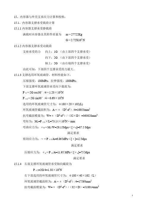
15、支腿的强度校核 15.1. 支腿所受载荷
4
15.1.1 储罐的满重 m0=38675kg 储罐的空重 m=8500kg 总高度 H=7070mm 外容器外直径 D0=2516mm 支腿个数 n=3 支腿材料〔σ 〕=113Mpa 15.1.2 容器受水平风力 P=K1K2q0f1l1D0x10-6 =0.7×1.70×600×1.63×7070×2516×10-6 =1.27X10⁴N P——水平风力 K1——体形系数,取 K1=0.7; K2——风振系数,取 K1=1.70; q0——该地区基本风压值,取 q0=600N/m2; f1——风压高度变化系数,选取 f1=1.63; l1——容器高度,l1=7070mm; D0——容器的外直径,D0=2516mm。 15.1.3 容器受水平地震力
m0 H E e Di
3
10 3
90.33 7070
38675 7070 103 0.077s 5 3 1.92 10 6.2 2500
a1=0.16,由 T=0.077s 查得 W——m0g=7070×9.8=6.9X10⁴N;
5
H——容器的总高度,H=7070mm; E——弹性模量,E=1.92X10⁵Mpa Di——外容器内直径,Di=2500mm。 δ e——外容器筒体有效厚度,δ e=6.2mm F1=P=1.27X10⁴N F2=F+0.25P=3.03X10⁴N+0.25X1.27X104=3.35X10⁴N 容器受水平力:FH=F2=3.35X10⁴N (在 F1 与 F2 中取大值)
管道应力计算指导

[转贴]压力管道应力分析部分第一章任务与职责1. 管道柔性设计的任务压力管道柔性设计的任务是使整个管道系统具有足够的柔性,用以防止由于管系的温度、自重、内压和外载或因管道支架受限和管道端点的附加位移而发生下列情况;1) 因应力过大或金属疲劳而引起管道破坏;2) 管道接头处泄漏;3) 管道的推力或力矩过大,而使与管道连接的设备产生过大的应力或变形,影响设备正常运行;4) 管道的推力或力矩过大引起管道支架破坏;2. 压力管道柔性设计常用标准和规范1) GB 50316-2000《工业金属管道设计规范》2) SH/T 3041-2002《石油化工管道柔性设计规范》3) SH 3039-2003《石油化工非埋地管道抗震设计通则》4) SH 3059-2001《石油化工管道设计器材选用通则》5) SH 3073-95《石油化工企业管道支吊架设计规范》6) JB/T 8130.1-1999《恒力弹簧支吊架》7) JB/T 8130.2-1999《可变弹簧支吊架》8) GB/T 12777-1999《金属波纹管膨胀节通用技术条件》9) HG/T 20645-1998《化工装置管道机械设计规定》10) GB 150-1998《钢制压力容器》3. 专业职责1) 应力分析(静力分析动力分析)2) 对重要管线的壁厚进行计算3) 对动设备管口受力进行校核计算4) 特殊管架设计4. 工作程序1) 工程规定2) 管道的基本情况3) 用固定点将复杂管系划分为简单管系,尽量利用自然补偿4) 用目测法判断管道是否进行柔性设计5) L型U型管系可采用图表法进行应力分析6) 立体管系可采用公式法进行应力分析7) 宜采用计算机分析方法进行柔性设计的管道8) 采用CAESAR II 进行应力分析9) 调整设备布置和管道布置10) 设置、调整支吊架11) 设置、调整补偿器12) 评定管道应力13) 评定设备接口受力14) 编制设计文件15) 施工现场技术服务5. 工程规定1) 适用范围2) 概述3) 设计采用的标准、规范及版本4) 温度、压力等计算条件的确定5) 分析中需要考虑的荷载及计算方法6) 应用的计算软件7) 需要进行详细应力分析的管道类别8) 管道应力的安全评定条件9) 机器设备的允许受力条件(或遵循的标准)10)防止法兰泄漏的条件11)膨胀节、弹簧等特殊元件的选用要求12)业主的特殊要求13)计算中的专门问题(如摩擦力、冷紧等的处理方法)14)不同专业间的接口关系15)环境设计荷载16)其它要求第二章压力管道柔性设计1. 管道的基础条件包括:介质温度压力管径壁厚材质荷载端点位移等。
API-620大罐计算表格

Area of A Ring, m2 Number of Sheets Needed by ring
Minimum Thickness of sheet in Ring 1, mm Thickness of Sheet I Ring 1 Nominal, mm Minimum Thickness of sheet in Ring 2, mm Thickness of Sheet on Ring 2 Nominal, mm Minimum Thickness of sheet in Ring 3, mm Thickness of Sheet on Ring 3 Nominal, mm Minimum Thickness of sheet in Ring 4, mm Thickness of Sheet on Ring 4 Nominal, mm
Rings= Aa=
NLanillo= TWALL-A1 = TWALL-A1n = TWALL-A2 = TWALL-A2n = TWALL-A3 = TWALL-A3n = TWALL-A4 = TWALL-A4n =
Density of the Sheet of Steel, Kg/m3 OUTPUTS
396.00 93.00 60.00 32.00 1.00 23,200.00 0.0625 25.00
20.00 8.00
14.86
7,901.42
4 140.09
10 6.8821
5.00 5.5157
4.00 4.1494
4.0LL-A5n =
TWALL-A6 = TWALL-A6n =
API-650-5

附录M—提高温度下储罐的操作要求M.1 范围M.1.1 本附录对最高操作温度超过90℃(200℉),但不超过260℃(500℉)的API 650标准储罐规定了附加要求。
M.1.2 下列情况,操作温度不得高于90℃(200℉):a.敞顶罐(参见3.9)。
b.浮顶罐(参见附录C)。
c.螺栓紧固的门板(参见A.10和A.11)。
d.结构支撑型铝拱顶(参见G.1.1和下面的注释)。
e.铝制内浮顶(参见H.3.2和下面的注释)。
f.塑料制内浮顶(参见H.3.4)。
注:如果符合下列要求,买方可以对上述d和e款允许有例外。
a. 按照ANSI/ASME B96.1《焊接铝金属储罐》确定降低铝合金许用应力,评估合金潜在的剥落。
b. 提高温度情况下评估垫圈和密封的适用性。
M.1.3 符合附录H的内浮顶罐,在操作温度高于90℃(200℉)时可以使用,但要受本附录相应要求的限制。
必须考虑液体的蒸汽压力。
密封装置,特别是那些纤维织物和非金属材料必须与操作温度相适应。
M.1.4 符合附录F的小的内压储罐,在操作温度高于90℃(200℉)时可以使用,但要符合M.3.6、M.3.7和M.3.8的要求。
M.1.5 车间组装的、符合附录J的储罐,在操作温度高于90℃(200℉)时可以使用,但要符合本附录的相应要求。
M.1.6 铭牌应在8.1.1的要求基础上增加“M”字样,表明罐是根据本附录制造的。
另外,在图8-1所示铭牌中的空白处应标注最高操作温度。
●M.2 热影响本附录不提供详细的规定以限制载荷和热影响引起的应变,如不同的热膨胀和热循环可能会存在于某些在提高温度下操作的储罐中。
对可能存在巨大热影响的场合,本附录的意图是买方应确定这种热影响。
制造厂应按买方的要求提供详图(要得到买方的认可)。
该详图的强度和用途应与本标准中的对没有这类热影响规定的详图相当。
对操作温度高于90℃(200℉)的情况,要特别考虑以下的热影响:a.罐底和罐壁较低部分之间的温差。
API-650储罐计算书
API 650储罐计算书内径:12.5米高度:9米设计内、外压: 2KPa/500PaTable of ContentsUser Input Data (3)Error Checker .LOG File (8)Wind, Material, Thickness & Weights (9)Roof Evaluation/Design & Appendix F (12)Seismic Analysis Results (13)Anchor Bolt Details (15)API-650 App I Grillage Review (16)API-650 App V External Pressure (17)Anchor Chair Calculations (18)Fluid Height Calculations (20)Wind Calculations (22)Thickness Calculations (24)Appendix F Calculations (27)Bolt Load Calculations (29)Seismic Analysis (31)Appendix V External Pressure (39)API-650/653 GENERAL TANK DATA :API-650 11th Edition, Addendum 3, Aug. 2011API Design Code ( 650 or 653 ) (650)Design Method (V, O, or A) ............................ O(V=variable, O=one foot, A=Appendix A)Run Objective (D=design, A=analyze) ................... ADesign Temperature ...............................(C ) 93.000Design Pressure at Top ....................(KPa ) 2.0000Shell Material ........................................ A-36Ratio of Normal Operating Pressure/Design Pressure [Fp] 0.40000Shell Design Stress [Sd] ..................(KPa ) 0.15995E+06 Shell Hydro Test Stress [St] ..............(KPa ) 0.17168E+06Tank Nominal Diameter [D] ........................(m. ) 12.500Tank Shell Height [HTK] ..........................(m. ) 9.0000Design Liquid Level [H] ..........................(m. ) 9.0000Liquid Specific Gravity [G] ........................... 0.85000Weight of Attachments/Structures..................(N. ) 30000.Distance down to Top Wind Girder .................(m. ) 0.00000 Joint Efficiency (App A or 653) [E] ................... 1.0000Wind Velocity .............................(M./sec. ) 37.500Insulation Thickness .............................(mm.) 40.000Insulation Density ........................(kg./cu.cm.) 0.22000E-03Include Annular Base Plate Details .................... YesInclude Wind Moment in Appendix F_4_2 Calculations .... YesNumber of Shell Courses (4)Shell Course # 1 Height ..........................(m. ) 2.2500Shell Course # 1 Thickness .......................(mm.) 10.000Shell Course # 1 Corrosion Allowance [CA] ........(mm.) 1.6000Shell Course # 2 Height ..........................(m. ) 2.2500Shell Course # 2 Thickness .......................(mm.) 10.000Shell Course # 2 Corrosion Allowance [CA] ........(mm.) 1.6000Shell Course # 3 Height ..........................(m. ) 2.2500Shell Course # 3 Thickness .......................(mm.) 10.000Shell Course # 3 Corrosion Allowance [CA] ........(mm.) 1.6000Shell Course # 4 Height ..........................(m. ) 2.2500Shell Course # 4 Thickness .......................(mm.) 10.000Shell Course # 4 Corrosion Allowance [CA] ........(mm.) 1.6000TANK SHELL COURSE MATERIALS :Shell Course # 1 Material Name ........................ A-36Shell Course # 1 Design Stress [Sd] .......(KPa ) 0.15995E+06 Shell Course # 1 Hydro Test Stress [St] ...(KPa ) 0.17168E+06 Shell Course # 1 Minimum Yield Stress .....(KPa ) 0.24821E+06 Shell Course # 1 Minimum Tensile Stress ...(KPa ) 0.39989E+06 Shell Course # 1 Maximum Thickness ..............(mm. ) 19.050Shell Course # 1 Material Grade .......................Shell Course # 1 Material Group (1)Shell Course # 2 Material Name ........................ A-36Shell Course # 2 Design Stress [Sd] .......(KPa ) 0.15995E+06 Shell Course # 2 Hydro Test Stress [St] ...(KPa ) 0.17168E+06 Shell Course # 2 Minimum Yield Stress .....(KPa ) 0.24821E+06 Shell Course # 2 Minimum Tensile Stress ...(KPa ) 0.39989E+06 Shell Course # 2 Maximum Thickness ..............(mm. ) 19.050Shell Course # 2 Material Grade .......................Shell Course # 2 Material Group (1)Shell Course # 3 Material Name ........................ A-36Shell Course # 3 Design Stress [Sd] .......(KPa ) 0.15995E+06 Shell Course # 3 Hydro Test Stress [St] ...(KPa ) 0.17168E+06 Shell Course # 3 Minimum Yield Stress .....(KPa ) 0.24821E+06 Shell Course # 3 Minimum Tensile Stress ...(KPa ) 0.39989E+06 Shell Course # 3 Maximum Thickness ..............(mm. ) 19.050Shell Course # 3 Material Grade .......................Shell Course # 3 Material Group (1)Shell Course # 4 Material Name ........................ A-36Shell Course # 4 Design Stress [Sd] .......(KPa ) 0.15995E+06 Shell Course # 4 Hydro Test Stress [St] ...(KPa ) 0.17168E+06 Shell Course # 4 Minimum Yield Stress .....(KPa ) 0.24821E+06 Shell Course # 4 Minimum Tensile Stress ...(KPa ) 0.39989E+06 Shell Course # 4 Maximum Thickness ..............(mm. ) 19.050Shell Course # 4 Material Grade .......................Shell Course # 4 Material Group (1)ANCHOR BOLT DETAILS :Anchor Bolt Diameter (optional) ..................(mm.) 44.450Threads per Unit Length ........................(1/mm.) 0.19685Bolt Allowable Stress .....................(KPa ) 0.15000E+06 Number of Anchor Bolts (optional) ..................... 20.000Bolt Yield Stress .........................(KPa ) 0.25000E+06 Bolt Offset from Mean Tank Diameter ..............(m. ) 0.10000Anchor Bolt Corrosion Allowance (optional) .......(mm.) 3.0000Wind Data :Kz parameter .......................................... 1.0400Kzt parameter ......................................... 1.0000Kd parameter .......................................... 0.95000Importance Factor (I) ................................. 1.0000Gust Factor (G) ....................................... 0.85000API-650 ROOF DETAILS SPECIFICATION :Roof Type (1-4) (4)(1=Supt Cone 2=Rafter Supt Cone 3=Cone 4=Dome 5=Umbrella)Angle Between Roof and Horizontal ................(deg) 24.610Net Area at Roof/Shell Junction [A] ...........(sq.mm.) 2000.5Thickness of Roof Plate ..........................(mm.) 10.000Roof Plate Corrosion Allowance ...................(mm.) 1.6000Weight of Snow on Roof ...........................(N. ) 0.00000 Roof Live Load ............................(N/M2 ) 1200.0---/ For General Roof, No Design /---Weight of Roof Plates ............................(N. ) 0.00000 Weight of Roof Framing ...........................(N. ) 0.00000 Pct of Weights Supported by Shell ..................... 0.00000---/ For Supported Cone Roof Design /---Preferred Rafter Type (W, WT, S, C) ...................Preferred Girder Type (W, WT, S, C) ...................Preferred Column Type (W, WT, S, C, DC, DI, P ) .......Roof Plate Material ................................... A-36Roof Plate Allowable Design Stress ........(KPa ) 0.15995E+06 Structural Member Material ............................ A-36Structural Member Allowable Design Stress..(KPa ) 0.15995E+06 Maximum Allowed Rafter Length ....................(m. ) -0.30788Maximum Allowed Girder Length ....................(m. ) -0.30788Center Column Cap Plate Diameter .................(m. ) 0.00000API-650 SEISMIC DATA (App E.) :Minimum Yield Strength of Bottom Plate .....(KPa 0.25000E+06 Minimum Yield Strength of Weld Material ....(KPa 0.25000E+06 Nominal Thickness of Bottom Plate (tb) ..........(mm. ) 8.0000Seismic Use Group (SUG)................................ 1.0000Friction Factor ....................................... 0.40000Importance Factor ..................................... 1.0000Initial Anchorage Type ................................ MEarthquake Type ....................................... SSite Class ............................................ 3.0000Spectral Acceleration Adjustment Coefficient (K) ...... 1.5000Scaling Factor (Q) .................................... 0.66700Transtiional Period (TL) .............................. 4.0000Mapped maximum earthquake for short periods (Ss) ...... 0.00000 Mapped maximum earthquake for 1 sec periods (S1) ...... 0.00000 Mapped maximum earthquake for 0 sec period (S0) ...... 0.00000 Non-ASCE peak ground acceleration (Sp) ................ 2.3000ASCE short period design acceleration parameter (SDS).. 0.00000 --- Site Specific Data ---Spectral acceleation parameter at 0 period (Sa0*) ..... 0.00000 Spectral acceleation parameter at any period (Sa*) .... 0.00000API-650 GRILLAGE REVIEW (App I.)Modulus of Elasticity of Bottom Plate .....(KPa ) 0.20200E+09 Corrosion Allowance added to Bottom Plate ......(mm. ) 1.5000Minimum Yield Strength of Bottom Plate ....(KPa ) 0.25000E+06 (Equal to Value from Seismic Data)SPECIFY ONE OF THE FOLLOWINGNominal Thickness of Bottom Plate ...............(mm. ) 8.0000(Equal to Value from Seismic Data )Maximum Allowed Spacing .........................(mm. ) 416.83API-650 External Pressure (App V.) :Specified External Pressure (Pe) ..........(N/M2 ) 500.00Elastic Modulus of Roof Plate Material ....(KPa ) 0.19900E+09 Bottom stiffener allow. compressive stress (KPa ) 0.15000E+06 Top stiffener allow. compressive stress ...(KPa ) 0.15000E+06 Nominal Thickness of Bottom Plate (tb) ..........(mm. ) 8.0000Smallest allowable tensile stress of roof,shell and stiffeners ....................(KPa ) 0.15000E+06 Roof Dish Radius ................................(m. ) 15.000Computation Control DirectivesROOF_PROJECTION_IN_WIND_MOMENT= YESSHELL_THICK_CONVERG_TOLERANCE= 0.12699999 mm.GENERATE_MESSAGE_FILE= NOCOSINE_CURVE_TOLERANCE= 0.30000001COSINE_CURVE_ITERATION_LIMIT= 100.00000WIND_GIRDER_SHELL_THICKNESS= MAXSHELL_SETTLEMENT_METHOD= FOURIER_SERIESCORRODED_NOZZLES= NO653_CORRODED_HYDROTEST_CASE= NOTHICKNESS_ROUNDUP_TO_NEAREST= 0.00000000 mm.PLATE_MATERIAL_DENSITY= 0.78500481E-02 kg./cu.cm. MODIFY_FLUID_HEIGHT_BY_PRESSURE= NOROUND_ANCHOR_BOLTS_BY= 4.0000000WIND_MOMENT_IN_APP_F= Sect_5.9.7.1FULL_SHELL_WEIGHT_IN_APP_F= YESUSE_P_FROM_F.4.1_ONLY_IN_F.6= YESUSE_NON_CORRODED_ROOF_WEIGHT_AS_DLR= NOYIELD_FOR_SEISMIC_IS_DERATED_FOR_TEMP= NOTANK(c) Intergraph CADWorx & Analysis Solutions, Inc. 2013C:\Users\yang\Desktop\法罗杰项目\大罐计算书\T-2303-zyh\新建文件夹\ Error Check Summary ReportFatal Errors 0Warning Messages 0Notes 0Error Checking CompletedWIND INFORMATIONAPI-650 11th Edition, Addendum 3, Aug. 2011Wind Velocity ............................(M./sec. ) 37.500Velocity Factor ...................................... 0.48866Wind Pressure ............................(KPa ) 0.96372Area Exposed to Wind .....................(m. **2) 131.22Sect 5.9.7.1 Wind Moment on Tank .........(N.m. ) 0.66347E+06 Wind Shear Force Acting on Tank ..........(N. ) 0.12646E+06MATERIAL PROPERTY INFORMATIONWind Girder Height Reduction Factor .................. 1.0000The following material properties have been modified inaccordance with API-650 (and API-653 where applicable).Course Material Design Test App MNumber Name Stress (Sd) Stress (St) Reduction(KPa ) (KPa )1 A-36 0.15995E+06 0.17168E+06 1.00002 A-36 0.15995E+06 0.17168E+06 1.00003 A-36 0.15995E+06 0.17168E+06 1.00004 A-36 0.15995E+06 0.17168E+06 1.0000SHELL COURSE THICKNESS DATA - One Foot MethodThickness Values for Three Cases MIN TEMPCOURSE DESIGN TEST USER (deg C )(mm. ) (mm. ) (mm. ) Status1 6.0000 6.0000 10.000 -8.8 PASS2 5.0000 5.0000 10.000 -8.8 PASS3 5.0000 5.0000 10.000 -8.8 PASS4 5.0000 5.0000 10.000 -8.8 PASSNote, "ANALYSIS" mode has been activated. From thispoint on, the user specified thicknesses will be usedfor all calculations. The above values for DESIGN andTEST thicknesses are for reference purposes only.SHELL COURSE ALLOWED FLUID HEIGHTSFluid Heights for Three CasesCOURSE DESIGN TEST REQUIRED(m. ) (m. ) (m. )1 26.107 28.328 9.00002 26.107 28.328 6.75003 26.107 28.328 4.50004 26.107 28.328 2.2500Maximum allowed fluid height of entire tank for:Design Thickness Case .................(m. ) 26.107Test Thickness Case .................(m. ) 28.328Required fluid height .................(m. ) 9.0000BASE PLATE DETAILS - SHELL WEIGHT & CENTER OF GRAVITYAnnular Base Plate Thickness .............(mm. ) 7.6000(from API-650 Table 5-1 plus corrosion)Annular Base Plate Width per 5.5.2 .......(mm. ) 670.40( 2 + ThkCrs1 + max[ 24, (390tb / sqrt(HG))] )Weight of Shell + Nozzles ................(N. ) 0.30269E+06 Total Weight of all Nozzles ..............(N. ) 0.00000 Center of Gravity (Shell+Nozzles) ........(m. ) 4.5000WIND OVERTURNING STABILITY CHECKCorroded Shell Weight + %Roof - Uplift ...(N. ) 0.19098E+06 wa .......................................(N./cm. ) 159.04Mw - moment due to wind (hor+ver) press ..(N.m. ) 0.75290E+06 Mpi - moment due to internal pressure ....(N.m. ) 0.15340E+07 Mf - moment due to tank liquid ...........(N.m. ) 0.39035E+07 Mdl - moment due to shell & roof .........(N.m. ) 0.18072E+07WIND GIRDER INFORMATIONFor "open top" tanks ...Required Section Modulus, Top Girder ...(mm. **3) 39767.Table 5-20 Detail, B value .............(mm. ) c 0.00Table 5-20 Shape name (if applicable)............... 4x3x.25Maximum Height of Unstiffened Shell ......(m. ) 138.59WIND GIRDER - TRANSFORMED SECTION METHODNumber of Intermediate Girders Reqd 0WEIGHT SUMMARY--------------Shell (Corroded) .............................(N. ): 228534. Shell (Non-Corroded) .........................(N. ): 272065. Annular Base Plate ...........................(N. ): 14701. Bottom Plate .................................(N. ): 76807. Nozzles ......................................(N. ): 0. Roof Plates ..................................(N. ): 106247. Roof Framing/Structure .......................(N. ): 0.Shell Attachments ............................(N. ): 30000. Insulation ...................................(N. ): 30621. Operating Fluid ..............................(N. ): 9187119. Water Weight .................................(N. ): 10808375.Operating Weight (Non-Corroded) ..............(N. ): 9717560. Test Weight (Non-Corroded) ...................(N. ): 11338816. Empty Weight (Non-Corroded) ..................(N. ): 530441.TANK(c) Intergraph CADWorx & Analysis Solutions, Inc. 2013TANK - Roof Design/Analysis DataAPI-650 11th Edition, Addendum 3, Aug. 2011SELF-SUPPORTING DOME ROOFRoof thickness per 5.10.6, 0.8D ......(mm. ): 5.7814Roof thickness per 5.10.6, 1.2D ......(mm. ): 7.8720Total weight of Roof Plates ...........(N. ): 0.10625E+06 (Based on user input thickness)User Specified Design Roof Load .......(KPa ): 2.1698(including user plate thickness)Computed Design Roof Load .............(KPa ): 2.1698(including user plate thickness)ROOF EVALUATIONS - Appendix FUplift force due to internal pressure..(N. ): 0.24543E+06 Total weight resisting uplift .........(N. ): 0.42191E+06Max Design Pressure, limited by uplift.(in of H2O ): 8.0954Max Design Pressure, limited by uplift.(KPa ): 2.0155(According to F.4.2)Max Design Pressure, roof/shell joint.(in of H2O ): 32.168Max Design Pressure, roof/shell joint.(KPa ): 8.0088(According to F.4.1)(Note, this value is limited by F.4.2 for further usage.)Compression Ring Failure Pressure .....(in of H2O ): 49.716Compression Ring Failure Pressure .....(KPa ): 12.378(According to F.6)Required Compression Areas, Roof/Shell JunctionArea as per Section F.5 ..............(mm. **2 ): 349.61Area as per Section 5.10.6, 0.8D ......(mm. **2 ): 231.37Area as per Section 5.10.6, 1.2D ......(mm. **2 ): 347.05FRANGIBLE ROOF-TO-SHELL JUNCTION AREA LIMITArea as per Section 5.10.2.6 ..........(mm. **2 ): 465.74Top Angle Requirement Per 5.1.5.9.e 2x2x1/4(This is a minimum angle size based solely on the tankdiameter. Other criteria may require a larger section.)TANK(c) Intergraph CADWorx & Analysis Solutions, Inc. 2013SEISMIC EVALUATION RESULTS - Appendix EAPI-650 11th Edition, Addendum 3, Aug. 2011Site-Specific Ground MotionDesign Fluid Weight (N. ) 0.91871E+07Sp -design level peak accel for nonASCE 2.3000Ss -MCE at period of 0.2 seconds 5.7500S0 -MCE at period of 0.0 seconds 2.3000S1 -MCD at period of 1.0 seconds 2.8750SDS-design spectral accel parameter 0.00000FA -acceleration based site coefficient 1.0000FV -velocity based site coefficient 1.3000TS - FvS1 / FaSs 0.65000TC -convective sloshing period (sec) 3.7200Ac -convective spectral accel parameter 0.00000 Ai -impulsive spectral accel parameter 0.00000 Wc -effective convective fluid weight(N. ) 0.29052E+07 Wi -effective impulsive fluid weight (N. ) 0.63741E+07 Vc -convective liquid base shear (N. ) 0.00000 Vi -impulsive liquid base shear (N. ) 0.00000 V -total design base shear (N. ) 0.00000VS -shear resistance (N. ) 0.38870E+07Xc -ring wall convective moment arm (m. ) 6.0467Xi -ring wall impulsive moment arm (m. ) 3.3750XCS-slab convective moment arm (m. ) 6.5034XIS-slab impulsive moment arm (m. ) 5.3604WS -shell+appurtenances weight (N. ) 0.33269E+06 Wrs-roof, framing 10% snow weight (N. ) 0.00000 Mrw-ringwall overturning moment (N.m. ) 0.00000 Ms -slab overturning moment (N.m. ) 0.00000AV -vertical acceleration parameter 0.00000 Ge -effective specific gravity 0.85000wa -resisting annulus force (N./cm. ) 192.27wt -tank + roof weight at shell base (N./cm. ) 84.719J -the anchorage ratio 0.00000L -reqd min annular plate projection (m. ) 0.00000Wab-Minimum anchorage resistance (N./cm. ) -22.220N -number of anchor bolts required 16Pab-anchor seismic design load (N. ) -5453.5 Sc -shell compressive stress (KPa ) 1008.6 Sa -shell allowable stress (KPa ) 42964.Height of sloshing wave (m. ) 6.2825 Required Freeboard (m. ) 4.3978Course Hoop Stress Hoop Allowable(KPa ) (KPa )1 46852. 0.21273E+062 35139. 0.21273E+063 23426. 0.21273E+064 11713. 0.21273E+06Seismic Evaluation Summary.Seismic shell stress check passed.Base shear within limits.Hoop stress within allowable.TANK(c) Intergraph CADWorx & Analysis Solutions, Inc. 2013ANCHOR BOLT DETAILS - Section 5.12API-650 11th Edition, Addendum 3, Aug. 2011Case Uplift Allowable Load/Bolt(N. ) Bolt Stress (N. )(KPa )Design Pressure : 0.00000 103419. 0.00000Test Pressure : 0.00000 137892. 0.00000Failure Pressure : 0.18473E+07 250000. 92367.Wind Loading : 0.00000 200000. 0.00000Seismic OPE : 0.00000 200000. 0.00000Design Press + Wind Load : 0.00000 137892. 0.00000 Design Press + Seismic OPE : 0.00000 200000. 0.00000 Frangibility Pressure : 0.41235E+07 250000. 0.20618E+06ANCHOR BOLT RESULTS - Section 5.12Case Number Bolt Bolt Stressof Bolts Diameter (KPa )(mm. )Design Pressure : 20 44.450 0.Test Pressure : 20 44.450 0.Failure Pressure : 20 44.450 88276.Wind Loading : 20 44.450 0.Seismic OPE : 20 44.450 0.Design Press + Wind Load : 20 44.450 0.Design Press + Seismic OPE : 20 44.450 0.Frangibility Pressure : 20 44.450 197042.Final Anchor Bolt Spacing .............. (m. ) 1.99Specified number of user bolts is sufficient.Specified user bolt diameter is sufficient.TANK(c) Intergraph CADWorx & Analysis Solutions, Inc. 2013API-650 APPENDIX I.7.3 GRILLAGE CHECKAPI-650 11th Edition, Addendum 3, Aug. 2011Uniform Pressure "p" ..................(KPa ): 91.18717 Computed Grillage Spacing ....................(mm.): 416.83304 Allowed Bottom Deflection ....................(mm.): 3.25000 Computed Bottom Deflection ...................(mm.): 1.40932TANK(c) Intergraph CADWorx & Analysis Solutions, Inc. 2013EXTERNAL PRESSURE RESULTS - Appendix VAPI-650 11th Edition, Addendum 3, Aug. 2011DL roof plate dead load ..............(N/M2 ) 769.8 PR design external pressure ..........(N/M2 ) 2169.8 For a Dome Roof:Required thickness of roof plate .....(mm. ) 7.001 Length of roof considered in region ..(mm. ) 196.456 Required area of roof/shell joint ....(mm. **2) 803.622 Required area of top stiffener ......(mm. **2) 0.000 Length of shell included (top) .......(mm. ) 150.031 Length of shell included (bottom) ....(mm. ) 150.031Transformed Shell Height .............(m. ) 9.000Elastic Buckling Check V.8.1.1Buckling Check Ok, exceeds 0.19 ................ 0.829Ps design ext press for shell .......(N/M2 ) 925.311 Ps(max) max design external pressure (N/M2 ) 8174.512 ts(min) min shell for design ext press (mm. ) 4.195Stiffeners are not required for external pressure.TANK(c) Intergraph CADWorx & Analysis Solutions, Inc. 2013Anchor Chair Cap Input Values:Thickness of Gusset Plates j 20.000 mm.Width of Gussets at Top Plate twdt 180.000 mm.Width of Gussets at Base Plate bwdt 40.000 mm.Height of Gussets Hg 240.000 mm.Height of Gussets plus top Plate thickness h 264.000 mm. Distance between Gussets g 100.000 mm.Dist. from Bolt Center to Gusset (Rg/2) cg 50.000 mm. External Corrosion Allowance Ca 2.0000 mm.Top Plate allowable stress S 250000.0 KPaNumber of Gussets per bolt ng 2Bottom Shell Course Thickness 10.000 mm.Shell Course Corrosion Allowance 1.6000 mm.Thickness of Tank Baseplate m 8.000 mm.Thickness of Top Plate c 24.000 mm.Radial Width of the Top Plate b 180.000 mm.Circumferential Width of the Top Plate a 280.000 mm. Anchor Bolt Diameter d 44.45 mm.Anchor Chair Cap and Gusset Plate Analysis Results:Required Thickness of Top Chair Cap Plate per AISI:P Bolt Loade Bolt eccentricity (center of bolt to shell OD)Sb Allowable Bending Stress ( 1.5 * S )g Distance between Gussetsd Bolt DiameterTop Chair Cap Plate Required Thickness per AISI [Tc]:= ( P /( Sb * e ) * ( 0.375 * g - 0.22 * d ))?+ c= (206175/(374999*95.000)*(0.375*100.00-0.22*44.450))?2.000= 14.6663 mm.Stress in the Top Plate at given Thickness [Stpl]:= P( 0.375 * b - 0.22 * d ) / e / ( c - Ca )?= 206175 (0.375*100.000 - 0.22*44.450 )/95.000 / (24.000 -2.000 )? = 124304.9 KPa , must be less than 375000.0 KPaRequired Gusset Thickness per AISI:Gusset Plate Thickness is the greater of( 0.5 in (12mm), 0.04( hg ))= max( 12.700 , 0.04( 240.000 ) ) + Ca= 14.700 mm.For gusset plates the following must also be true:Gusset Thickness * Average Gusset Width >= (P/1000)/25= ( 20.000 - 2.000 ) * 120.000 > ( 206.175 / 25 ) Passed= 2160.000 > 8.247 PassedLocal Stress at the Top Plate per AISI, including axial Stress [S]:= P*e/t瞇1.32*Z/(1.43*a*h?(R*t)+ (4(a)(h)?.333 + 0.031 /(R*t)?= 206175*95.00/8.40瞇1.32*0.94/(1.43*280.00*(264.00)?(6251.60*8.40) + (4*280.00 (264.00 )?0.333 + 0.031/(6251.60 *8.40 )?= 397491.9 KPaIntermediate Value [Z]:= 1/[(0.177*a*m/(R*t)?*(m/t)?+ 1]= 1/[(0.177*280.000*8.000/(6251.600*8.400)?*(8.000/8.400)?1]= 0.942Radial Distance [e]:= ( Dc - Ds ) / 2= ( 12690.000 - 12500.000 ) / 2= 95.000 mm.TANK(c) Intergraph CADWorx & Analysis Solutions, Inc. 2013Determine Maximum allowed Fluid Heights:For Course # 1, Operating CaseAllowed fluid height above this course based on the 1ft method= (Td - ca)Sd/(2.6 * D * G ) + X/12= (0.3937 - 0.0630 )23199.32 /(2.6 * 41.0 * 0.850 ) + 12.000 /12 = 85.651 ft. [26.107 m.]For Course # 1, Hydro Case, not corrodedAllowed fluid height above this course based on the 1ft method= (Td - ca)Sd/(2.6 * D * G ) + X/12= (0.3937 - 0.0000 )24900.65 /(2.6 * 41.0 * 1.000 ) + 12.000 /12 = 92.941 ft. [28.328 m.]For Course # 2, Operating CaseAllowed fluid height above this course based on the 1ft method= (Td - ca)Sd/(2.6 * D * G ) + X/12= (0.3937 - 0.0630 )23199.32 /(2.6 * 41.0 * 0.850 ) + 12.000 /12 = 85.651 ft. [26.107 m.]For Course # 2, Hydro Case, not corrodedAllowed fluid height above this course based on the 1ft method= (Td - ca)Sd/(2.6 * D * G ) + X/12= (0.3937 - 0.0000 )24900.65 /(2.6 * 41.0 * 1.000 ) + 12.000 /12 = 92.941 ft. [28.328 m.]For Course # 3, Operating CaseAllowed fluid height above this course based on the 1ft method= (Td - ca)Sd/(2.6 * D * G ) + X/12= (0.3937 - 0.0630 )23199.32 /(2.6 * 41.0 * 0.850 ) + 12.000 /12 = 85.651 ft. [26.107 m.]For Course # 3, Hydro Case, not corrodedAllowed fluid height above this course based on the 1ft method= (Td - ca)Sd/(2.6 * D * G ) + X/12= (0.3937 - 0.0000 )24900.65 /(2.6 * 41.0 * 1.000 ) + 12.000 /12 = 92.941 ft. [28.328 m.]For Course # 4, Operating CaseAllowed fluid height above this course based on the 1ft method= (Td - ca)Sd/(2.6 * D * G ) + X/12= (0.3937 - 0.0630 )23199.32 /(2.6 * 41.0 * 0.850 ) + 12.000 /12 = 85.651 ft. [26.107 m.]For Course # 4, Hydro Case, not corrodedAllowed fluid height above this course based on the 1ft method= (Td - ca)Sd/(2.6 * D * G ) + X/12= (0.3937 - 0.0000 )24900.65 /(2.6 * 41.0 * 1.000 ) + 12.000 /12 = 92.941 ft. [28.328 m.]Appendix M Yield Stress reduction factor, M.3.6 [Mfact]:= Yield Reduction Factor * Fy / Fyamb= 1.000 * 36000.6 / 30000.0= 1.000 Must be less than or equal to 1.0Total Design External Pressure Loading per V.7 [Pr]:= max[ DL + (Lr or S) + 0.4Pe, DL + Pe + 0.4(Lr or S)]= max[ 16.078 + max[25.063 , 0.000 ] + 0.4 * 10.443 ,16.078 + 10.443 + 0.4 * max[25.063 , 0.000 ]]= max[ 45.318 , 36.546 ]= 45.318 psf [2169.822 N/M2]Moment about shell-to-bottom joint [MDL]:= ( Shell Weight + Attachement Weight + Framing Weight * % )D/2 = ( 58263.3 + 6744.6 + 0.0 * 0.00 )41.0 /2= 1333003.2 ft.lb [1807232.5 N.m.]Design Pressure per F.4.1 [P]:= (0.962 * A * Fy * tan(theta))/(D^2) + 0.245 * DLR/D^2= (0.962*3.101*36000.0*tan(24.61))/(41.0^2)+0.245*20060/41.0^2= 32.168 in. of water [817.077 mm. of water]= 1.162 psi [8.009 KPa]Note: Design Pressure was less than maximum computed per F.4.1Moment about shell-to-bottom joint [MDLR]:= ( Roof Weight )D/2= ( 20060.4 )41.0 /2= 411344.4 ft.lb [557684.3 N.m.]TANK(c) Intergraph CADWorx & Analysis Solutions, Inc. 2013Wind Load Calculations:Wind velocity factor 5.2.1 [Vfact]:= ( Wind Velocity / 120 )^2= ( 83.9 / 120 )^2= 0.489Vertical projected wind area of tank [VArea]:= Tank Height * Tank Diameter= 29.53 * 41.01= 1210.940 ft^2 [112.500 m.^2]Velocity pressure per 5.9.7.1 [p]:= 0.00256 * Kz * Kzt * kd * V^2 * I * G + 5.0= 0.00256 * 1.040 * 1.000 * 0.950 * 83.885^2 * 1.000 * 0.850 + 5.0 = 20.128 psf [963.737 N/M2]Wind moment on shell [Moment]:= Wind Pressure * Wind Area * Tank Height/2= 20.128 * 1210.9 * 29.53 /2= 0.35985E+06 ft.lb. [0.48787E+06 N.m.]Vertical projected wind area of Dome/Umbrella roof:Radius of the apex:= 0.8 D= 0.8 * 41.010= 32.808 ft. [10.000 m.]Half angle between tank and apex radii:= asin( D / (2 * Rapex) )= asin( 41.010 / (2 * 32.808 ) )= 38.683 deg.Area of the sector:= 2 * Half angle / ( 2 pi ) * ( pi * Rapex^2 )= 2 * 0.675 / ( 2 * 3.142 ) * ( 3.142 * 32.808^2 )= 726.706 ft.^2 [67.513 m.^2]Height from apex to chord:= Rapex * cos(Half angle)= 32.808 * cos(0.675 )= 25.611 ft. [7.806 m.]Area of triangle below the chord line:= Apex height * D/2= 25.611 * 41.010 /2= 525.161 ft.^2 [48.789 m.^2]Dome/Umberlla roof area:= Sector area - Triangle area= 726.706 - 525.161= 201.545 ft.^2 [18.724 m.^2]Area Exposed to Wind:= Wind area of tank + Wind area of roof= 1210.940 + 201.545= 1412.485 ft.^2 [131.224 m.^2]Wind Moment at the base including the dome/umbrella roof [Total Moment]:= Moment + ( Wind P * Roof Area( Tank Height + dome Height/3)) = 359851.9 + ( 20.128 * 201.5 ( 29.5 + 7.20 /3))= 489369.469 ft.lb. [663467.562 N.m.]Wind shear force acting on the tank:= Wind Pressure * (tank area + roof area)= 20.128 * 1412.5= 0.28431E+05 lbf. [0.12646E+06 N.]TANK(c) Intergraph CADWorx & Analysis Solutions, Inc. 2013。
API650-6_7_8_9-翻译解读
6—制造6.1 概述6.1.1 工艺6.1.1.1 制造API650 标准储罐的全部工作,应符合本标准和在询价或订购单中认可的替换规定。
制备工艺与加工等都应是优良的,并接受制造单位检查人员最为严格的检查,不管买方是否放弃了某些检验项目。
6.1.1.2 当材料要求矫正时,应在下料和成型之前用加压或其它无害的方法进行。
除非将材料加热到锻造温度,否则不允许加热或用锤击的方法矫正。
6.1.1.3 用于辅助储罐制造的材料不应对储罐的结构完整性产生不良影响。
润滑油、有色粉笔、胶粘剂和焊接防飞溅喷剂不应包含对储罐产生不良影响的材料,如用于不锈钢材料的硫、氯化合物。
即将焊接到压力边界上的连接件,在焊缝12 mm (0.5 in.)范围内的焊缝区均不应有锌涂层或镉涂层。
6.1.2 板边加工板边可以剪切、机械加工、铲削、或自动火焰切割。
对焊接头,剪切板厚最大为10 mm(3/8in.);搭接接头,剪切板厚最大为16 mm (5/8in.)。
注:经买方同意,对焊接头,剪切板厚最大可为16 mm (5/8in.)。
火焰切割的板边应均匀光滑,焊前应去掉氧化皮和焊渣等堆积物。
切削或剪切边缘要用钢丝刷刷过。
边缘表面上薄的锈膜不需要除去。
罐顶和罐底板的圆周边缘可以用氧气切割。
• 6.1.3 壁板成型图6-1中提供了储罐安装之前符合储罐曲率的壁板成型标准。
如果储罐直径超出图6-1规定的限值,或者如果制造方关于任何直径的替代程序获得买方接受,则允许壁板成型与罐壁安装同时进行。
6.1.4 标记所有切割成型专用钢板和罐顶支撑构件,在包装起运前应按制造图注上标记。
6.1.5 运输装运的钢板和储罐材料,应保证交货时不受损伤。
对螺栓、螺母、螺纹管接头及其它小的零部件应装箱、装桶或装袋交运。
所有法兰面和其它机械加工表面应采取防腐蚀和防止物理损伤的保护措施。
6.2 车间检验6.2.1 在任何时候执行合同规定的任何工作时,买方检验人员应能自由进入与合同有关的任何制造车间之内。
15-常压API 650储罐

ATMOSPHERIC API 650 STORAGE TANKS常压API 650储罐FOREWORD序言This specification covers the minimum requirements for the design and fabrication of Field Erected Steel Storage Tanks used in the petroleum and petrochemical industries.This specification is intended to supplement API Standard 650, which is part of this specification. Paragraph numbers of this specification correspond to those in API 650. Paragraph numbers not found in API 650 are new paragraphs.该技术规范包括用于石油和石油化工业现场安装的钢制储罐设计和制造的最低要求。
该技术规范是对API 标准650的补充,是该技术规范的一部分。
该技术规范的段落数与API650的段落数相对应。
API 650中没有的段落为新增加的段落。
Paragraphs shall be highlighted as shown below to indicate the type of change from the API Standard:段落应加以标记(如下所示),以标明由API标准变化的情况:(Addition) New paragraph or supplemental requirements/clarifications to an existing paragraph.(新增)新增段落或对现有段落的补充要求/说明(Deleted) Paragraph deleted.(删减)段落已删除(Revision) A revision has been made as required.(修改)按要求已进行的修改。
船用LNG储罐与管道应力计算

船用LNG储罐与管道应力计算甘绍警;周瑞平;甘少炜;苏阳【摘要】For the specific characteristics of LNG, marine LNG tank and pipelines have to meet certain requirements for strength. Therefore, the strength calculation on the tank and pipelines is indispensable. The outer tank wall connects to the pipelines directly. Hence, its deformation at the pipeline connections has a great impact on the value and distribution of the pipeline stress. With the aid of FEM, this paper completed the modeling analysis of marine LNG tank and pipeline respect-ively, as well as twice stress check on the pipeline, taking the deformation at the pipeline connections as displacement load-ing. Finally, the stress analysis method on marine LNG tank and pipelines has been explored, which will provide the theoret-ical basis for the designs of tank and pipelines.%船用LNG储罐和管道因传输特殊性质的LNG介质,储罐和管道必须满足相关的强度要求.因此,对储罐和管道应力计算十分必要.储罐的外罐体直接与管道相连接,外罐在管道接口处的变形,对LNG管道应力值和分布有很大影响.文本运用有限元方法,对某型船用LNG储罐和管道分别进行建模分析,将外罐体管道接口处的应变作为管道位移载荷,对管道一次应力和二次应力校核,探索船用LNG储罐和管道应力分析方法,为储罐和管道设计提供理论依据.【期刊名称】《舰船科学技术》【年(卷),期】2018(040)001【总页数】6页(P35-40)【关键词】船用LNG储罐;管道;应力计算【作者】甘绍警;周瑞平;甘少炜;苏阳【作者单位】武汉理工大学能源与动力工程学院,湖北武汉 430063;武汉理工大学能源与动力工程学院,湖北武汉 430063;中国船级社武汉规范研究所,湖北武汉430020;武汉理工大学能源与动力工程学院,湖北武汉 430063【正文语种】中文【中图分类】U664.840 引言随着人们环保意识的提高,清洁能源得到越来越广泛的关注,液化天然气(Liquefied Natural Gas,LNG)以其环保和经济性等特点,逐步被人们青睐。
- 1、下载文档前请自行甄别文档内容的完整性,平台不提供额外的编辑、内容补充、找答案等附加服务。
- 2、"仅部分预览"的文档,不可在线预览部分如存在完整性等问题,可反馈申请退款(可完整预览的文档不适用该条件!)。
- 3、如文档侵犯您的权益,请联系客服反馈,我们会尽快为您处理(人工客服工作时间:9:00-18:30)。
API650 储罐接管应力计算表格
一、前言
API650是美国石油工程协会(American Petroleum Institute)制定的用于设计和建造储罐的标准,该标准涵盖了储罐的材料、设计、制造、安装和检验等方面。
储罐是储存石油、化工品和其他液体物质的重要设施,在设计和建造过程中需要考虑各种力学应力,以确保储罐的安全运行。
接管是储罐的重要组成部分,用于连接储罐本体和其他设备或管道。
在接管的设计中,需要进行应力计算,以确保接管在使用过程中不会发生破坏或失效。
本文将介绍使用API650标准进行储罐接管应力计算的相关内容,并给出应力计算表格的具体格式和内容。
二、应力计算公式
储罐接管的应力计算通常包括以下几种力学应力:轴向力、弯矩、剪切力和压力。
根据API650标准,这些应力可以采用以下公式进行计算:
1. 轴向力:对于受拉或受压的接管,轴向力可以通过以下公式计算:
其中,\(P\)代表轴向力,\(F\)代表接管上的作用力,\(A\)代表接管的横截面积。
2. 弯矩:接管在使用过程中可能受到弯矩的作用,弯矩可以通过以下公式计算:
\[M = F \times L\]
其中,\(M\)代表弯矩,\(F\)代表接管上的作用力,\(L\)代表力臂的长度。
3. 剪切力:剪切力可以通过以下公式计算:
\[V = \frac{F}{A}\]
其中,\(V\)代表剪切力,\(F\)代表接管上的作用力,\(A\)代表接管的横截面积。
4. 压力:接管在使用过程中还会受到内部或外部的压力作用,压力可以通过以下公式计算:
其中,\(P\)代表压力,\(F\)代表接管上的作用力,\(A\)代表接管的受
压面积。
根据API650标准的规定,进行接管应力计算时,需要考虑外部载荷、内部压力以及接管的几何形状和材料性质等因素,以确保接管在设计
使用条件下不会发生破坏或失效。
三、应力计算表格
为了方便工程师进行接管应力计算,API650标准中给出了应力计算表格的具体格式和内容。
应力计算表格通常包括以下几个方面的内容:
1. 接管基本信息:表格中首先需要填写接管的基本信息,包括接管的
型号、规格、材料等内容。
2. 轴向力计算:接管在使用过程中可能受到轴向拉力或压力的作用,
需要填写轴向力的计算结果,包括受力情况、作用力、接管横截面积
和计算结果等内容。
3. 弯矩计算:接管在使用过程中可能受到弯矩的作用,需要填写弯矩
的计算结果,包括受力情况、作用力、力臂长度和计算结果等内容。
4. 剪切力计算:接管在使用过程中可能受到剪切力的作用,需要填写
剪切力的计算结果,包括受力情况、作用力、接管横截面积和计算结
果等内容。
5. 压力计算:接管在使用过程中可能受到内部或外部的压力作用,需
要填写压力的计算结果,包括受力情况、作用力、接管受压面积和计
算结果等内容。
应力计算表格的格式和内容应当符合API650标准的要求,以便工程
师能够清晰、准确地进行接管应力计算,确保设计的合理性和安全性。
四、结论
储罐接管应力计算是储罐设计和建造过程中的重要内容,通过合理的
应力计算可以确保接管在使用过程中不会发生失效或破坏,保障储罐
的安全运行。
API650标准给出了接管应力计算的相关公式和表格格式,工程师应当严格按照标准要求进行计算和填写,以确保储罐接管的设
计和使用安全可靠。
储罐接管应力计算表格是储罐设计和建造过程中不可或缺的一部分,
工程师们应当充分理解和掌握相关内容,确保接管设计的合理性和安
全性。
API650标准为工程师提供了规范的指导和要求,有助于工程
师们进行准确、可靠的接管应力计算工作,为储罐的设计和建造提供有力支持。