门禁系统使用说明书
门禁系统使用说明书

门禁系统使用说明书内部编号:(YUUT-TBBY-MMUT-URRUY-UOOY-DBUYI-0128)安装、使用产品前,请阅读安装使用说明书。
请妥善保管好本手册,以便日后能随时查阅。
GST-DJ6000系列可视对讲系统液晶室外主机安装使用说明书目录一、概述 (1)二、特点 (2)三、技术特性 (3)四、结构特征与工作原理 (3)五、安装与调试 (5)六、使用及操作 (10)七、故障分析与排除 (16)海湾安全技术有限公司一概述GST-DJ6000可视对讲系统是海湾公司开发的集对讲、监视、锁控、呼救、报警等功能于一体的新一代可视对讲产品。
产品造型美观,系统配置灵活,是一套技术先进、功能齐全的可视对讲系统。
GST-DJ6100系列液晶室外主机是一置于单元门口的可视对讲设备。
本系列产品具有呼叫住户、呼叫管理中心、密码开单元门、刷卡开门和刷卡巡更等功能,并支持胁迫报警。
当同一单元具有多个入口时,使用室外主机可以实现多出入口可视对讲模式。
GST-DJ6100系列液晶室外主机分两类(以下简称室外主机),十二种型号产品:黑白可视室外主机a)GST-DJ6116可视室外主机(黑白);b)GST-DJ6118可视室外主机(黑白);c)GST-DJ6116I IC卡可视室外主机(黑白);d)GST-DJ6118I IC卡可视室外主机(黑白);e)GST-DJ6116I(MIFARE)IC卡可视室外主机(黑白);f)GST-DJ6118I(MIFARE)IC卡可视室外主机(黑白)。
彩色可视液晶室外主机g)GST-DJ6116C可视室外主机(彩色);h)GST-DJ6118C可视室外主机(彩色);i)GST-DJ6116CI IC卡可视室外主机(彩色);j)GST-DJ6118CI IC卡可视室外主机(彩色);k)GST-DJ6116CI(MIFARE)IC卡可视室外主机(彩色);GST-DJ6118CI(MIFARE)IC卡可视室外主机(彩色)。
门禁管理系统使用说明书

乌石化汽车定量装车系统门禁管理系统使用说明书河北珠峰仪器仪表设备有限公司目录一、系统组成...............................................错误!未定义书签。
二、道闸....................................................错误!未定义书签。
1.主要特点..................................... 错误!未定义书签。
2. 设备组成..................................... 错误!未定义书签。
3. 基本工作原理................................. 错误!未定义书签。
4. 设备使用说明................................. 错误!未定义书签。
三、车辆检测器.............................................错误!未定义书签。
1. 车辆检测器的安装............................. 错误!未定义书签。
2. 主要技术参数................................. 错误!未定义书签。
3. 车辆检测器的接线图........................... 错误!未定义书签。
4. 车辆检测器灵敏度设置......................... 错误!未定义书签。
四、门禁控制器.............................................错误!未定义书签。
五、读卡器 .................................................错误!未定义书签。
六、车牌识别...............................................错误!未定义书签。
门禁系统使用说明书

目录一系统概述 (01)二系统操作 (04)三系统编程 (09)四系统配置及选材 (19)五系统原理图 (21)六系统连线示意图 (25)七安装调试 (29)八系统各部件的安装说明 (31)九其它事项 (31)备注:本手册中所提及的终端设备(门口机、分机、管理机、围墙机),除特别说明外,主要是以可视系统AB-6A-402的设备为主。
.一、系统概述AB-6A-402楼宇对讲系统是采用单片机微电脑控制技术,数位总线传输技术而设计的小区联网可视对讲系统。
系统数据传输距离可达5000米(需加中继器),防雷抗干扰,可实现大型小区的系统联网。
AB-6A-401楼宇对讲系统是非可视系统,除无视频外,其余性能与AB-6A-402系统相同。
两种系统主要适用于高楼大厦房型。
整个系统由门口主机(带联网功能)、室内分机、信号隔离器、主机电源、管理中心、管理中心电源、多门选择器、围墙机、信号中继器以及联网信号切换器等设备构成。
(见下表)...页◇编码门口主机AB-402D长×宽×厚(mm)外形尺寸:316×136×56开孔尺寸:280×114×34◇可视室内分机长×宽×厚(mm)外形尺寸:220×205×65(AB-402M)235×188×50(AB-402MQ)◇信号隔离器(AB-402A,AB-402B)长×宽×厚(mm)外形尺寸:85×85×37..页◇ 主机电源/隔离器电源/管理中心电源(UPS-DP/UPS-P/UPS-CP )长×宽×厚(mm)外形尺寸:190×180×73◇ 管理中心(AB-602C )长×宽×厚(mm)外形尺寸:240×267×65二、系统操作(一)门口机(402D )与用户分机通话1.来访者键入用户分机号码,若号码正确,则门口机发出悦耳的回铃声,呼叫开始。
安全门禁系统的操作指南说明书
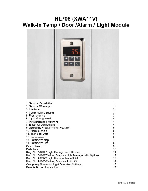
NL708 (XWA11V)Walk-In Temp / Door /Alarm / Light Module1. General Description 12. General Warnings 13. Interface 24. Temp Alarms Setting 35. Programming 36. Light Management 47. Installation and Mounting 48. Electrical Connections 49. Use of the Programming “Hot Key” 510. Alarm Signals 511. Technical Data 612. Connections 613. Parameter Map 714. Parameter List 8Quick Sheet 9Parts Lists 10Dwg. No. A32907 Light Manager with Options 11Dwg. No. B10007 Wiring Diagram Light Manager with Options 12Dwg. No. A32942 Light Manager Retrofit Kit 13Dwg. No. B10020 Wiring Diagram Retro Kit 14 Occupancy Sensor for Light Operation Settings 15Remote Buzzer Installation 171. GENERAL DESCRIPTIONModel XWA11V, 100x64 mm format, is a microprocessor-based controller, suitable for temperature monitoring and alarming in a walk-in cooler or freezer. It is provided with two (2) Relay Contacts to control lights and an external alarm. It is provided with one (1) NTC probe input for temperature measurement. The unit has 2 Digital Inputs, one for a Door Switch and the 2nd as an optional Panic Switch. See the catalog for optional accessories. One 5Pin Input allows the user to program the parameter list with a “Hot Key” (see section 9)Note: The default settings are listed in the back of this manual. They are set for Coolers (Medium Temp). For Freezers (Low Temp) you MUST Change the ALL and ALU settings. See Section 4.02. GENERAL WARNINGS2.1 PLEASE READ BEFORE USING THIS MANUAL∙This manual is part of the product and should be kept close to the instrument for easy and quick reference. ∙The instrument shall not be used for purposes different from those described hereunder. It cannot be used as a safety device.∙Check the application limits before proceeding.Note: If equipped with a battery backup, the battery must be installed after the walk-in has reached its operating temperature.2.2 SAFETY PRECAUTIONSCheck if the supply voltage is correct before connecting the instrument.∙Do not expose the back of the instrument to water or moisture: use the controller only within the operating limits avoiding sudden temperature changes with high atmospheric humidity to prevent the formation of condensation.∙Warning: disconnect all electrical connections before performing any maintenance operation.∙Fit the probe where it is not damaged by the end-user. The instrument must not be opened.∙In case of failure or faulty operation send the instrument back to the distributor (see address) with a detailed description of the fault.∙Consider the maximum current that can be applied to each relay (see Technical Data).In Programming Mode press to select a parameter or to confirm an operation.Press and hold this key for more than 5 s to turn the controller OFF.Press and hold this key for more than 1 s to turn the controller back ON.Press to see the HIGH Temp ALARM (ALU parameter)Press to see the LOW Temp ALARM (ALL parameter)In Programming Mode press to browse parameter codes.Press to increase the displayed value.Press to mute the buzzer (+ relay) when an ALARM is happening.Hot key programming: with the instrument on, insert the hot key and then press the UPbutton.In Programming Mode press to browse parameter codes.Press to decreases the displayed value.Switch ON and OFF the light of the cold roomKEY COMBINATIONS: PRESS SIMULTANEOUSLYTo lock and unlock the Keyboard.To enter the Programming Mode.To exit the Programming Mode.To enter a new value for the HIGH Temp ALARM (ALU).To enter a new value for the LOW Temp ALARM (ALL).Each LED function is described in the following table:∙To modify the minimum (LOW) Temp ALARM: hold the keys pressed for 3 s until the minimum Temp alarm is displayed.∙Change the value using the UP and DOWN keys.∙Press the SET key to confirm the new value and exit.∙To modify the max (HIGH) Temp ALARM: hold the keys pressed for 3 s until the max Temp alarm is displayed.∙Change the value using the UP and DOWN keys.∙Press the SET key to confirm the new value and exit.5. PROGRAMMING1. Enter the Programming Mode by pressing the SET and DOWN key for 3s ( and will start blinking).2. Select the required parameter. By using the UP or DOWN KEY3. Press the “SET” key to display its value (now only the LED is blinking).4. Use “UP” or “DOWN” to change i ts value.Press “SET” to store the new value and move to the following parameter.To exit: Press SET + UP or wait 15 s without pressing a key.NOTE: the set value is stored even when the procedure is exited, by waiting the time-out to expire.5.2.1 HOW TO ENTER THE HIDDEN MENU (PR2)1. Enter the Programming Mode by pressing the Set + down key for 3s ( and starts blinking).2. When a parameter is displayed, release and re-press the SET + down for more than 7s.3. The Pr2 label will be displayed immediately followed from the HY parameter. NOW YOU ARE IN THEHIDDEN MENU.4. Select the required parameter as above5. Press the “SET” key to display its value (Now only the LED is blinking).6. Use “UP” or “down” to change its value.7. Press “SET” to store the new value and move to the following parameter.To exit: Press SET + up or wait 15s without pressing a key.NOTE: the set value is stored even when the procedure is exited by waiting the time-out to expire.5.2.2 HOW TO MOVE A PARAMETER FROM THE HIDDEN MENU TO THE FIRST LEVEL ANDVICEVERSAEach parameter present in the HIDDEN MENU can be removed or put into “THE FIRST LEVEL” (user level) by pressing “SET + down”.In HIDDEN MENU when a parameter is present in First Level the decimal point LED is on.1. Keep pressed for more than 3s the UP and DOWN keys.2. The “POF” message will be displayed and the keyboard will be locked. At this point it will be possibleonly to see the Set Point or the MAX or MIN Temp stored6. LIGHT MANAGEMENTThe LHt timer is re-initialized every time the light button is pushed.With LHt=0 the light remains on until the light button is pushed again.The light is switched on every time one of the following conditions happens:∙the door is open (i1F = dor)∙the presence sensor is activated (i2F = LHt)∙the light button is pushedThe light is switched off when all the following conditions happen:∙the LHt timer is exhausted∙the door is closed (i1F = dor)∙the presence sensor is de-activated (i2F = LHt)∙Light button regulation: i1L = nThe lights will flash (for 2 minutes) every 20 seconds for the FLH time (0-5 min) at the end of the LHt time as a warning that the lights are about to turn off (for incandescent and LED lights only).The light button has a higher priority than digital inputs therefore:- if the light was switched on by button the digital input can not modify its status.- if the light was switched on by digital input, the light button can modify its status.7. INSTALLATION AND MOUNTINGThe XWA11V must be mounted on vertical panel, in a J-Box (Steel City PN 68371-1/2) or equal or wall mounted using an appropriate enclosure.The Ambient Temp range for correct operation is 32 – 131°F (0-55°C). Avoidinstallation in places subject to strong vibrations, corrosive gases, excessive dirt orhumidity. The same recommendations apply to probes..110”for the digital and analog inputs. Relays and power supply have a Fast-on connection (.250”). For supply connections, use 14 AWG or larger cop per or CU wire only rated at least 90˚C (194˚F). Before connecting cables make sure the power supply complies with the instrument requirements. Separate the probe cables from the power supply cables, from the outputs and the power connections. Do not exceed the maximum current allowed on each relay and in case of heavier loads use a suitable external relay.N.B. Maximum current allowed for all the loads is 15A.recommended to place the thermostat probe away from air streams to correctly measure the average room2. When the controller is ON, insert the “Hot key” and push UP key; the "uPL" message appears followed aby flashing “End”3. P ush “SET” key and the End will stop flashing.4. Turn OFF the instrument remove the “Hot Key”, then turn it ON again.NOTE: the “Err” message is displayed for failed programming. In this case push UP key again if you want to restart the upload again or remove the “Hot key” to abort the operation.2. Insert a programmed “Hot Key” into the 5 PIN receptacle and then turn the Controller ON.3. Automatically the parameter list of the “Hot Key” is downloaded into the Controller memory, the “doL”message is blinking followed a by flashing “End”.4. After 10 seconds the instrument will restart working with the new parameters.5. Remove the “Hot Key”.NOTE the message “Err” is displayed for failed programming. In this case turn the unit off and then on if you want to restart the download again or remove the “Hot key” to abort the operation.The alarm message is displayed until the alarm condition is reset.operation. Check connections before replacing the probe.T° alarms “HA” and “LA” automatically stop as soon as the thermostat T° returns to normal values or when the defrost starts.Door switch alarm “dA” stops as soon as the door is closed.External alarms “EAL”, “BAL” stops as soon as the external digital input is disabled.Housing: self extinguishing ABSCase: face 100x64 mm; depth 45.5mmMounting: J-box or wall-mount in suitable enclosureFrontal protection: IP65Connections: ¼” fast-on for power, 1/8” fast-on for probes and Digital Inputs Power supply: 120Vac ± 10%, optional 230Vac ± 10% MAX 15APower absorption: 4VA max.Ambient Temperature: 32-131°F (0-55°C)Display: 3 digits, red LED, 14,2 mm high.Inputs: 1 NTC probeDigital inputs: 2 free voltagesRelay outputs: Relay ContactsLight: relay SPST 15A, 120Vac;Alarm: relay SPST 8A, 120VacOther output: alarm buzzerData storing: on the non-volatile memory (EEPROM).Measuring and regulation range:NTC probe: -40÷110°C (-58÷230°F)Resolution: 1 °FAccuracy : ±1 °FPower supply: 120Vac +/- 10% 15A MAX currentOt Thermostat probe calibration: (-12.0÷12.0°C/ -21÷21°F) allows to adjust possible offset of the thermostat probe.CF T measurement unit: °C = Celsius; °F = Fahrenheit. When the measurement unit is changed the Set Point and the values of some parameters have to be modified.rES Resolution (for °C): (in = 1°C; dE = 0.1 °C) allows decimal point display.Ut Display update: The time delay of the T readout (0÷255s)onF Off function enabling: n = off function disabled; y = off function enabled;ALU High T° alarm setting: (ALL ÷ 150°C or 302°F);when this T° is reached and after the ALd delay time the HA alarm is enabled.ALL Low T° alarm setting: (- 50°C or -58°F ÷ ALU)when this T° is reached and after the ALd delay time, the LA alarm is enabled,.AFH T° alarm differential: (0,1÷25,5°C; 1÷45°F) differential for T° alarm Set Point and fan regulation Set Point, always a positive valueALd T° alarm delay: (0÷255 min) time interval between the detection of an alarm condition and the corresponding alarm signaling.dAO Delay of T° alarm at start-up: (0min÷23h 50min) time interval between the detection of the T° alarm condition after the instrument power on and the alarm signaling.EdA Alarm delay at the end of defrost: (0÷255 min) Time interval between the detection of the T° alarm condition at the end of defrost and the alarm signaling.dot Delay of T° alarm after closing the door: (0÷255 min) Time delay to signal the T° alarm condition after closing the door.LHt Light timer: (0-255 min)The time the light will stay on after pressing the light switch on the keyboard.FLH Light Flashing: (0-5 min)The light will “double flash” every 20 seconds during the FLH time period before turning off after the LHt time. (For incandescent and LED lights only.)doA Open door alarm delay:(0÷255 min) delay between the detection of the open door condition and its alarm signaling: the flashing message “dA” is displayed.oA1 First relay configuration: (14-15): ALr = alarm; LHt = light; onF = on/off relayoA2 Second relay configuration: (14-16): ALr = alarm; LHt = light; onF = on/off relayAOP Alarm relay polarity: cL = closing contacts; oP = opening contacts.i1P Digital input 1 polarity (1-2): CL : the digital input is activated by closing the contact;OP: the digital input is activated by opening the contacti1L Door switch to turn light ON(1-2): (y / no) To turn the light ON automatically when the door is open. The light will turn off based on LHt . Keyboard switch must be turned ON first.i1F Digital input 1 operating mode(1-2): EAL = external alarm; dor = door switch; dFr = A defrost is running; LHt = keep light ON (signal from occupancy sensor) override LHt.;i2P Digital input 2 polarity (1-3): CL : the digital input is activated by closing the contact;OP: the digital input is activated by opening the contacti2F Digital input 2 operating mode: configure the digital input function:EAL= External alarm;PAn =Panic alarm;dFr= A defrost is running; (need external CT’s)LHt = Keep light ON (signal from occupancy sensor) overrides LHt.did Time interval/delay for digital input alarm:(0÷255 min.) If I2F=EAL or PAn (external alarms), “did” parameter defines the time delay between the detection and the successi ve signaling of thealarm.tbA Alarm relay & Buzzer disabling: (y ; no)Pbc Type of probe (PTC, NTC)dP1 Probe 1 TrEL Software release for internal use.Ptb Parameter table code: read only.QUICK SHEETXWA11V Walk-in Alarm / Door / Alarm / Light Unit Operation ManualIn Normal Operation the Indicator will display the temperature. 36° FCHECK ALARM SETPOINTS (Cooler HA = 50°F, LA = 30°F / Freezer HA = 30°F, LA = -20°F)To SEE the HIGH Alarm Set Point Press and release the Key, It will display the High Set Point for 5 seconds. The Temp alarm will go ON if the temp exceeds the Set Point after 15 minutes. The display will read HA alternating with the Temp.To SEE the LOW Alarm Set Point Press and release the Key it will display the Low Set Point for 5 seconds. The Temp alarm will go ON if the temp exceeds the Set Point after 15 minutes. LA, alternating with the Temp.CHANGE ALARM SETPOINTS1. To Change the HIGH Alarm Set Point Press BOTH the for 7 secondsand the LED above the will blink.2. Release and scroll UP to adjust the Set Point up, or Scroll DOWN to adjustthe Set point down.3. Press to confirm the change.4. For Low Set Point repeat the procedure with theLIGHT OPERATIONPress the light switch to turn ON the inside light; it will automatically go OFF after 15 minutes.DOOR SWITCHIf the door switch is used opening the door will automatically turn the light ON, and will automatically go OFF after 15 minutes.If the Door is left open longer than 15 minutes the DOOR Alarm will go off, dA alternating with the temperature reading.ALARM SIGNALSWalk-In Alarm System Parts ListRemote Buzzer Box InstallationInstallation:1. Mount the remote buzzer box in the location desired.2. Drill the appropriate size hole for the conduit fitting into the Wall Mount Box P/N 142456.3. Conduit, conduit fittings, and wire are by others.Installation must be by a qualified electrician per the applicable national and local codes.4. Connect a black wire to terminal #4 and a white wire to terminal #13 of the Phone Relay in the Wall5. Mount Box.NOTESNOTES10/14 Rev G 14249820。
IC门禁系统操作说明书
IC门禁系统操作说明书IC门禁系统操作说明书 (1)1.门禁系统操作流程图 (2)2.资料设定菜单设置 (3)3.人事信息设置 (4)3.1部门资料录入或导入 (4)3.2人事资料录入或导入 (6)4.设备管理菜单设置 (8)5.机器设置 (9)6.发卡 (10)7.设置各种门禁权限 (11)7.1门禁状态时间设置 (11)7.2通行时间设置 (12)7.3 假日通行设置 (13)7.4 超级用户设置 (15)7.5电子地图管理 (16)8.下载通行名单 (20)9.数据读取 (22)10.相关报表 (22)11.卡片挂失、解挂、补办新卡操作流程 (24)12.离职操作流程 (25)13.附加功能 (26)1.门禁系统操作流程图2.资料设定菜单设置2.1资料设定-系统参数-基本参数自动生成工号(递增):新员工建立人事资料时,在人事资料里自动生成工号,并且每个新工号数字会自动递增1位。
工号长度:设置工号的位数。
(最大12位);自动生成卡号(递增):新员工建立人事资料时,在人事资料里自动生成卡号,并且每个新工号数字会自动递增1位。
卡号长度:设置卡号的位数。
建议设置为5-7位卡号,卡号最长不能超过1048575。
单据需要审核生效:考勤管理里面的事务登记的单据需要通过单据审核中心审核才有效。
启用部门权限:主要决定用户权限里的部门权限分配是否启动。
启用卡钟权限:主要决定用户权限里的卡钟权限分配是否启动。
2.2资料设定-系统参数-门禁参数门禁通行密码:当启用卡+密码开门的时,每个人刷卡输入的密码,密码可定义为工号,卡号,或者用户在人事资料自行定义处理提示门禁卡检测:当钩上该选项,人事资料设定启用卡终止日期的时候,到终止日期,软件会提示过期,需用户进行相应处理注:门禁卡检测只是一个软件提示,不会自动删除门禁通行权限,需手工删除权限使用扇区:此参数设置好后,所有卡片发卡都发到定义的这个扇区里,此参数初次使用时设置好后,就不要随便改动,防止卡片发到不同的扇区,导致有些卡无法消费。
门禁管理系统使用说明书

门禁管理系统使用说明书乌石化汽车定量装车系统门禁管理系统使用说明书河北珠峰仪器仪表设备有限公司.08.03目录一、系统组成 .............................................................. 错误!未定义书签。
二、道闸 ...................................................................... 错误!未定义书签。
1.主要特点 ....................................................... 错误!未定义书签。
2. 设备组成 ......................................................... 错误!未定义书签。
3. 基本工作原理.................................................. 错误!未定义书签。
4. 设备使用说明.................................................. 错误!未定义书签。
三、车辆检测器 .......................................................... 错误!未定义书签。
1. 车辆检测器的安装......................................... 错误!未定义书签。
2. 主要技术参数................................................. 错误!未定义书签。
3. 车辆检测器的接线图 ..................................... 错误!未定义书签。
4. 车辆检测器灵敏度设置 ................................. 错误!未定义书签。
恒安博门禁说明书
恒安博门禁说明书恒安博门禁系统说明书第一章概述1.1 产品概述恒安博门禁系统是一种用于控制人员进出特定区域或场所的安全管理系统。
通过使用该系统,管理员可以实现对人员的身份认证和进出门禁区域的控制,提高场所的安全性和管理效率。
1.2 产品特点1.2.1 高安全性:恒安博门禁系统采用先进的身份认证技术,如指纹、刷卡、密码等,确保只有授权人员才能进出门禁区域。
1.2.2 灵活性:恒安博门禁系统支持多种身份认证方式,管理员可以根据实际需求选择最合适的认证方式。
1.2.3 可扩展性:恒安博门禁系统支持多种设备连接方式,可以根据不同场所的需求,扩展连接更多的门禁设备,实现全面的门禁控制。
1.2.4 数据统计和报表功能:恒安博门禁系统可以记录人员进出门禁区域的时间和地点,根据需求生成统计和报表,帮助管理员更好地管理人员出入情况。
第二章安装与设置2.1 安装前准备在安装恒安博门禁系统之前,请确保已准备好以下物品:- 恒安博门禁系统主机- 门禁读卡器- 门禁控制器- 电源适配器- 门闩- 网络线- 门禁软件安装光盘2.2 安装步骤2.2.1 安装主机第一步,将恒安博门禁系统主机放置在安装位置上,并固定好。
第二步,将主机与电源适配器连接,并接通电源。
2.2.2 安装读卡器和控制器第一步,根据实际需求,选择合适的门禁读卡器和控制器,并固定在门禁口的合适位置。
第二步,将读卡器和控制器与主机连接,确保连接稳定。
2.2.3 安装门闩根据需要安装门闩,确保在人员认证通过后能够自动开启或关闭。
2.2.4 连接网络将主机与局域网连接,确保可以实现远程监控和管理。
2.3 软件设置2.3.1 安装门禁管理软件使用提供的安装光盘安装门禁管理软件,并按照软件说明进行设置。
2.3.2 添加用户在门禁管理软件中添加管理员和其他用户,并设置相应的权限。
2.3.3 设置门禁区域在门禁管理软件中设置门禁区域的名称和具体位置信息。
2.3.4 设置身份认证方式在门禁管理软件中设置支持的身份认证方式,如指纹、刷卡、密码等。
门禁系统说明书
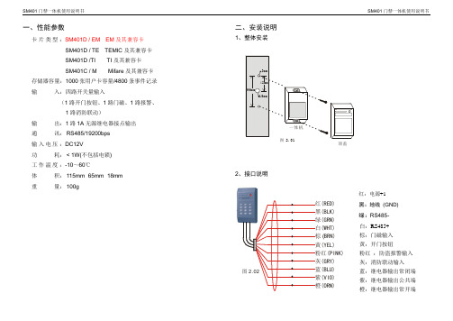
一、性能参数卡片类型:SM401D / EM EM及其兼容卡SM401D / TE TEMIC及其兼容卡SM401D /TI TI及其兼容卡SM401C / M Mifare及其兼容卡存储器容量:1000张用户卡容量/4800条事件记录输入:四路开关量输入(1路开门按钮、1路门磁、1路报警、1路消防联动)输出:1路1A无源继电器接点输出通讯: RS485/19200bps输入电压:DC12V功耗: < 1W(不包括电锁)工作温度:-10~60℃体积: 115mm×65mm×18mm重量: 100g 二、安装说明1、整体安装2、接口说明红:电源+1黑:地线(GND)绿:RS485-白:RS485+棕:门磁输入黄:开门按钮粉红:防盗报警输入灰:消防联动输入蓝:继电器输出常闭端紫:继电器输出公共端橙:继电器输出常开端图 2.01顶盖图 2.02红黑绿白棕黄粉红灰蓝紫橙(RED)(BLK)(GRN)(WHT)BRN)(YEL)(PINK)(GRY)(BLU)(VIO)(ORN)(13、接线说明(1) 使用门禁专用电源接线图单元接线图一单元接线图一(2) 使用通用电源(通电开锁型)接线图(3) 使用通用电源(断电开锁型)接线图注:电锁电流不超过1A单元接线图二门禁专用电源24、系统安装说明 (1) 单元连接示意图(2) 系统连接示意图RS485通讯线通讯适配器图 2.07*通讯适配器可以采用RS485/232转换器或RS485网卡。
RVVP20.3名称线型通讯线×报警输入门磁信号线电锁控制线电源线RVVP20.3RVVP20.3RVVP20.5RVVP20.5RVVP2X0.3××××消防联动注意:当管理电脑与门禁控制器通讯线距离超过一千米的时候,要添加通讯中继器RS485图 2.06开门按钮报警输入消防联动门磁电锁20.3×20.3×20.3×注:电锁电流不超过1A单元接线图三5、安装注意事项●所有通讯线以及控制线等要单独走管,不能与强电靠或平行走线。
- 1、下载文档前请自行甄别文档内容的完整性,平台不提供额外的编辑、内容补充、找答案等附加服务。
- 2、"仅部分预览"的文档,不可在线预览部分如存在完整性等问题,可反馈申请退款(可完整预览的文档不适用该条件!)。
- 3、如文档侵犯您的权益,请联系客服反馈,我们会尽快为您处理(人工客服工作时间:9:00-18:30)。
门禁系统使用说明书
一、系统概述
门禁系统是一种用于控制人员进出特定区域的安全设施。
本门禁系
统使用说明书旨在帮助用户正确、高效地操作门禁系统,确保系统正
常运行,达到安全管理的目的。
二、系统组成
1. 门禁主机:安装在门禁控制房内,负责管理和控制整个门禁系统。
主机具备用户管理、权限分配、记录查询等功能。
2. 门禁读卡器:安装在控制区域的门禁位置,负责读取用户卡片上
的信息,并将其发送给门禁主机进行验证。
3. 电磁锁:安装在门禁位置的门框上,通过电流控制门的开关。
当
门禁主机验证通过后,门禁读卡器会发送信号给电磁锁,使得门能够
打开。
4. 指纹识别仪(可选):用于指纹识别的设备,提供更高级别的身
份验证。
5. 告警装置(可选):用于监测未授权进入或异常情况,并发出警报。
三、使用步骤
1. 用户注册
用户需要首先注册个人信息,并获得一张门禁卡。
在门禁主机的用户管理界面中,选择“注册新用户”并按照提示输入姓名、身份证号码等信息。
注册成功后,用户将获得一张有效的门禁卡。
2. 刷卡进门
用户在进入控制区域时,将门禁卡放置在门禁读卡器上。
读卡器将自动读取卡片上的信息并发送给门禁主机进行验证。
若验证通过,门禁主机将发送信号给电磁锁,门会自动打开,用户可以进入。
3. 退出区域
当用户需要离开控制区域时,只需轻推门,门禁系统将自动检测到用户的离开,并将门自动关闭。
4. 权限管理
门禁系统支持多级权限管理,管理员可以通过门禁主机进行权限分配。
用户的权限将决定其能否进入某些特定区域。
在门禁主机的管理界面,选择“权限管理”功能,管理员可设定用户的权限级别。
5. 记录查询
门禁系统会自动记录用户的进出时间和门禁卡号,并存储在门禁主机中。
管理员可以通过门禁主机的记录查询功能,查看特定时间段内用户的进出记录。
通过该功能,管理员可以进行安全管理和监控。
四、注意事项
1. 用户对自己的门禁卡负有保管责任,不得将门禁卡借给他人使用。
若门禁卡遗失或损坏,应及时向管理员报告,由管理员注销失效并重
新发放。
2. 刷卡进入区域时,请确保门禁卡与读卡器的接触干净、紧密,以
免影响验证的准确性。
3. 用户在控制区域内应遵守相关规定,不得擅自进入未授权区域或
触碰任何安全设备。
4. 严禁对门禁系统进行任何恶意操作或损害系统设备,否则将承担
相应的法律责任。
五、常见问题解答
1. 为什么门禁卡刷了多次也无法进入?
答:可能是门禁卡损坏或权限设置有误,请及时联系管理员进行处理。
2. 我忘记携带门禁卡怎么办?
答:请联系管理员,管理员可通过特定方式验证您的身份并开门。
3. 是否可以转让门禁卡?
答:严禁将门禁卡转让给他人,一旦发现将取消该卡的权限。
4. 如何查询自己的进出记录?
答:用户可通过门禁主机上的记录查询功能,查看特定时间段内的进出记录。
六、系统维护
门禁系统由专业维护人员进行日常维护和保养。
若发现系统故障或异常情况,请及时向管理员报告,并等待维护人员进行处理。
七、总结
本门禁系统使用说明书详细介绍了门禁系统的组成、使用步骤、注意事项和常见问题解答。
用户在使用门禁系统时,请遵守相应规定,并及时与管理员沟通交流,以确保系统的正常运行和安全管理。
注:本说明书仅适用于一般门禁系统的使用,如有特殊定制需求,请与供应商或相关专业人士联系。