岩土工程专业翻译英文原文和译文
土木工程岩土外文翻译
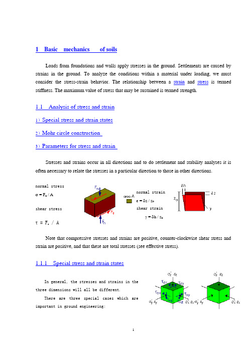
1 Basic mechanics of soilsLoads from foundations and walls apply stresses in the ground. Settlements are caused by strains in the ground. To analyze the conditions within a material under loading, we must consider the stress-strain behavior. The relationship between a strain and stress is termed stiffness. The maximum value of stress that may be sustained is termed strength.1.1 Analysis of stress and strain1)Special stress and strain states2)Mohr circle construction3)Parameters for stress and strainStresses and strains occur in all directions and to do settlement and stability analyses it is often necessary to relate the stresses in a particular direction to those in other directions.normal stress σ = F n / Ashear stressτ = F s/ A normal strain ε = δz / z oshear strainγ = δh / z oNote that compressive stresses and strains are positive, counter-clockwise shear stress and strain are positive, and that these are total stresses (see effective stress).1.1.1 Special stress and strain statesIn general, the stresses and strains in the three dimensions will all be different.There are three special cases which are important in ground engineering:General case princpal stressesAxially symmetric or triaxial statesStresses and strains in two dorections are equal.σ'x = σ'y and εx = εyRelevant to conditions near relatively small foundations,piles, anchors and other concentrated load s.P lane strain:Strain in one direction = 0εy = 0Relevant to conditions near long foundations,embankments, retaining walls and other long structures.One-dimensional compression:Strain in two directions = 0εx = εy = 0Relevant to conditions below wide foundations orrelatively thin compressible soil layers.Uniaxial compressionσ'x = σ'y = 0This is an artifical case which is only possible for soil isthere are negative pore water pressures.1.1.2 Mohr circle constructionrelate to a particular plane within an element of soil. Ingeneral, the stresses on another plane will be different.To visualise the stresses on all the possible planes,a graph called the Mohr circle is drawn by plotting a(normal stress, shear stress) point for a plane at everypossible angle.There are special planes on which the shearstress is zero (i.e. the circle crosses the normal stressaxis), and the state of stress (i.e. the circle) can be described by the normal stresses acting on these planes; these are called the principal stresses '1 and '3 .1.1.3 Parameters for stress and strainIn common soil tests, cylindrical samples are used in which the axial and radial stresses and strains are principal stresses and strains. For analysis of test data, and to develop soil mechanics theories, it is usual to combine these into mean (or normal) components which influence volume changes, and deviator (or shearing) components which influence shape changes.In the Mohr circle construction t' is the radius of the circle and s' defines its centre. Note: Total and effective stresses are related to pore pressure u:p' = p - u s' = s - u q' = q t' = t1.2 StrengthThe shear strength of a material is most simply described as the maximum shear stress it can sustain: When the shear stress is incre ased, the shear strain increases; there will be a limiting condition at which the shear strain becomes very large and the material fails; the shear stress f is then the shear strength of the material. The simple type of failure shown here is associatedwith ductile or plastic materials. If the material is brittle (like a piece of chalk), the failure may be sudden and catastrophic with loss of strength after failure.1.2.1 Types of failureMaterials can fail under different loading conditions. In each case, however, failure is associated with the limiting radius of the Mohr circle, i.e. the maximum shear stress. The following common examples are shown in terms of total stresses:ShearingShear strength = τfσnf = normal stress at failureUniaxial extensionTensile strength σtf = 2τfUniaxial compressionCompressive strength σcf = 2τfNote:Water has no strength f = 0.Hence vertical and horizontal stresses are equal and the Mohr circle becomes a point.1.2.2 Strength criteriaA strength criterion is a formula which relates the strength of a material to some other parameters: these are material parameters and may include other stresses.For soils there are three important strength criteria: the correct criterion depends on the nature of the soil and on whether the loading is drained or undrained.In General, course grained soils will "drain" very quickly (in engineering terms) following loading. Thefore development of excess pore pressure will not occur; volume change associated with increments of effective stress will control the behaviour and the Mohr-Coulomb criteria will be valid.Fine grained saturated soils will respond to loading initially by generating e xcess pore water pressures and remaining at constant volume. At this stage the Tresca criteria, which uses total stress to represent undrained behaviour, should be used. This is the short term or immediate loading response. Once the pore pressure has dissapated, after a certain time, the effective stresses have incresed and the Mohr-Coulomb criterion will describe the strength mobilised. This is the long term loading response.1.2.2.1 Tresca criterionThe strength is independent of the normal stress since the response to loading simple increases the pore water pressure and not theeffective stress.The shear strength f is a materialparameter which is known as the undrained shearstrength su.τf = (σa - σr) = constant1.2.2.2 Mohr-Coulomb (c'=0) criterionThe strength increases linearly with increasingnormal stress and is zero when the normal stress is zero.'f = 'n tan '' is the angle of frictionIn the Mohr-Coulomb criterion the materialparameter is the angle of friction and materials which meet this criterion are known as frictional. In soils, the Mohr-Coulomb criterion applies when the normal stress is an effective normal stress.1.2.2.3 Mohr-Coulomb (c'>0) criterionThe strength increases linearly with increasingnormal stress and is positive when the normal stress iszero.'f = c' + 'n tan '' is the angle of frictionc' is the 'cohesion' interceptIn soils, the Mohr-Coulomb criterion applies when the normal stress is an effective normal stress. In soils, the cohesion in the effective stress Mohr-Coulomb criterion is not the same as the cohesion (or undrained strength su) in the Tresca criterion.1.2.3Typical values of shear strengthOften the value of c' deduced from laboratory test results (in the shear testing apperatus) may appear to indicate some shar strength at ' = 0. i.e. the particles 'cohereing' together or are 'cemented' in some way. Often this is due to fitting a c', ' l ine to the experimental data and an 'apparent' cohesion may be deduced due to suction or dilatancy.1 土的基本性质来自地基和墙壁的荷载会在土地上产生应力。
岩土工程专业翻译英文原文和译文

According to the yield design (or limit analysis) reasoning, the above structure will remain safe under a given vertical load Q(force per unit length along the Oz axis), if one can exhibit throughout the rock mass a stress distribution which satisfies the equilibrium equations along with the stress boundary conditions,while complying with the strength requirement expressed at any point of the structure. This problem amounts to evaluating the ultimate load Q﹢ beyond which failure will occur, or equivalently within which its stability is ensured. Due to the strong heterogeneity of the jointed rock mass, insurmountable difficulties are likely to arise when trying to implement the above reasoning directly. As regards, for instance, the case where the strength properties of the joints are considerably lower than those of the rock matrix, the implementation of a kinematic approach would require the use of failure mechanisms involving velocity jumps
土木工程专业文献翻译中英文
The frame structure anti- earthquake conceptdesignThe disaster has an earthquake dashing forward sending out nature, may forecast nature very low so far, bring about loss for human society is that the natural disaster of all kinds is hit by one of the gravest disaster gravely. In the light of now available our country science level and economy condition, correct the target building seismic resistance having brought forward "three standards " fortification, be that generally, the what be spoken "small earthquake shocks does not but constructs in the dirty trick, big earthquakes do not fall ". That generally, what be talked small shocks in the earthquake, big earthquakes refer to respectively is intensity exceed probability in 50 fortifying for 3%'s 63% , 10% , 2 ~ being more is caught in an earthquake, earthquake , rare Yu earthquake.Since building the astigmatic design complexity, in actual project, anti-knock conceptual design appears especially important right away. It includes the following content mainly: Architectural design should pay attention to the architectural systematic ness; Choose rational building structure system; the tensile resisting inclining force structure and the component is designed.That the ability designs law is the main content that the structure denasality designs includes standard our country internal force adjustment and structure two aspect. It is twenty centuries seventies later stage , reinforced concrete structure brought forward by famous New Zealand scholar T.Paulay and Park has sufficient tonsillitis method under the force designing an earthquake chooses value is prejudiced low situationW.hose core thought is: "The beam cuts organization " or "the beam column cuts organization " by the fact that "the strong weak post beam " guides structure to take form; Avoid structure by "strong weak scissors turn " before reach estimate that shearing happened in the denasality in the ability front destroy; Turn an ability and consume an ability by the fact that necessary structure measure makes the location may form the plasticity hinge have the necessary plasticity. Make structure have the necessary tonsillitis from all above three aspect guarantee. That framed structure is the common structure form, whose senility certainly designs that, is to embody from about this three aspect also mainly.1, Strong pillar weak beamDriving force reaction analysis indicates structure; architectural deformability is connected with to destroying mechanism. Common have three kinds model’s consume energ y organization ", beam hinge organization ““, post hinge organization ““, beam column hinge organization "."Beam hinge organization " and "beam column hinge organization " Lang Xianknuckle under , may let the entire frame have distribution and energy consumption heavier than big internal forces ability, limit tier displacement is big , plasticity hinge quantity is many , the hinge does not lose efficacy but the structure entirety does not lose efficacy because of individual plasticity. The as a result anti-knock function is easy to be that the armored concrete is ideal consume energy organization. Being that our country norm adopts allows a pillar , the shearing force wall puts up the hinge beam column hinge scheme, taking place adopting "strong relative weak post beam " measure , postponing a pillar cuts time. Weak tier of post hinge organization possibility appear on unable complete trouble shooting but , require that the axis pressure restricting a pillar compares as a result, architectural weakness prevents necessary time from appearing tier by the fact that Cheng analysis law judges now and then, post hinge organization.Are that V. I. P. is to enhance the pillar bending resistance , guidance holds in the beam appear first, the plasticity cuts our "strong common weak post beam " adjustment measure. Before plasticity hinge appearing on structure, structure component Yin La District concrete dehiscence and pressure area concrete mistake elasticity character, every component stiffness reduces a reinforced bar will do with the cementation degeneration between the concrete. That stiffness reduces a beam is relatively graver than accepting the pillar pressing on , structure enhances from initial shearing type deformation to curved scissors shape deformation transition , curved post inner regulation proportion really more curved than beam; The at the same time architectural period is lengthened, size affecting the participation modulus shaking a type respectively to structure's; Change happened in the earthquake force modulus , lead to the part pillar bend regulation enhancing, feasible beam reality knuckles under intensity rise , the post inner bends regulation when plasticity hinge appearing on thereby feasible beam enhancing since structure cause and the people who designs the middle reinforced bar's are to enhance.. And after plasticity hinge appearing on structure, same existence having above-mentioned cause, structure knuckles under mistake elasticity in the day after tomorrow process being that process , post that the earthquake enhances strenuously further bend regulation enhancing with earthquake force but enhance. The force arouses an earthquake overturn force moment having changed the actual post inner axis force. We knuckle under the ability lessening than axis pressure in standardizing being limited to be able to ensure that the pillar also can lead to a pillar in big the bias voltage range inner , axis force diminution like value. The anti-knock norm is stipulated: Except that the frame top storey and post axis pressure are compared to the strut beam and frame pillar being smaller than 0.15 person and frame, post holds curved regulation designing that value should accord with differencebeing,that first order takes 1.4 , the two stage takes 1.2 , grade-three takes 1.1. 9 degree and one step of framed structure still responds to coincidence,,intensity standard value ascertains that according to matchingreinforced bar area and material really. The bottom post axis is strenuously big, the ability that the plasticity rotates dispatches, be that pressure collapses after avoiding a foot stall producing a hinge, one, two, three steps of framed structure bottom, post holds cross section constituting curved regulation designing that value takes advantage of that 1.5, 1.25 compose in reply 1.15 in order to enhancing a modulus respectively. Combination of the corner post adjustment queen bends regulation still should take advantage of that not to be smaller than 1.10's modular. Curved regulation designs that value carries out adjustment to one-level anti-knock grade shearing force wall limb cross section combination , force the plasticity hinge to appear to reinforce location in the wall limb bottom, the bottom reinforces location and all above layer of curved regulation designing that value takes wall limb bottom cross section constituting curved regulation designing value , other location multiplies 1.2's by to enhance a modulus. Prop up anti-knock wall structure to part frame, bottom-end , whose curved combination regulation design value respond to one, two steps of frame pillars post upper end and bottom post take advantage of that 1.5 composes in reply 1.25 in order to enhancing a modulus respectively. All above "strong weak post beam” adjustment measure, reaction analysis indicates , big satisfied fundamental earthquakes demand no upside down course nonlinearity driving force. Reinforced bar spending area, the beam in 7 is controlled from gravity load, the post reinforced bar matches’ tendon rates basically from the min imum under the control of. Have enhanced post Liana Xiang all round resisting the curved ability. At the same time, 7 degree of area exactly curved regulation plasticity hinge appears on disaster very much, plays arrive at advantageous role to fighting against big earthquakes. In 9 degree of area, adopt reality to match reinforced bar area and material bending regulation within intensity standard value calculation post, structural beam reinforced bar enhancing same lead to enhancing bending regulation within post designing value, under importing in many waves, the beam holds the plasticity hinge rotating developing greatly, more sufficient, post holds the plasticity hinge developing insufficiency, rotate less. Design demand with the beam. Reaction and 9 degree are about the same to 8 degree of area , whose big earthquake displacement , that post holds the plasticity hinge is bigger than rotating 9 degree much but, the beam holds the plasticity hinge appearing sufficient but rotate small, as a result "strong weak post beam " effect is not obvious , curved regulation enhances a modulus ought to take 1.35 , this waits for improving and perfecting going a step further when the grade suggesting that 8 degree of two stage is anti-knock in connection with the expert.2, Strong shear weak curved"Strong weak scissors turn” is that the plasticity cuts cross section for guarantee on reach anticipate that shearing happened in the mistake elastic-deformation prior to destroy. As far as common structure be concerned, main behaviors holds in the beam, post holds, the shearing force wall bottom reinforces area , shearing force wall entrance to a cave company beam tools , beam column node core area. Show mainly with being not that seismic resistance is compared with each other, strengthening measure in improving the effect shearing force;Aspect adjusting a shear bearing the weight of two forces.1)effect shearing forceOne, two, three-level frame beam and anti-knock wall middle stride over high ratio greater than 2.5 company beam, shearing force design value amongthem, first order choose 1.3, two stage choose 1.2, three-level choose 1.1, first order framed structure and 9 Due Shan respond to coincidence. Coincidence one, two, three steps of frame post and frame pillar , shearing force being designed being worth taking 1.4 among them, one step , taking 1.2, three steps of take 1.1 , one-level framed structure and 9 Due Shank two steps responding to.One, two, three steps of anti-knock walls bottom reinforces location the shearing force designs that value is among them, first order takes 1.6 , the two stage takes 1.4 , grade-three takes 1.2, 9 Dud Shank respond to coincidence. The node core area seismic resistance the beam columnnode , one, two steps of anti-knock grades are carried out is born the weight of force checking calculation by the scissors , should accord with anti-knock structure measure about 3 step, correct 9 degree of fortify and one-level anti-knock grade framed structure, think to the beam end the plasticity hinge already appears , the node shearing force holds reality completely from the beam knuckling under curved regulation decision , hold reality according to the beam matching reinforced bar covering an area of the growing modulus that intensity standard value calculation, takes advantage of that at the same time with 1.15 with material. Other first order holds curved regulation according to the beamdesigning that value secretly schemes against , the shearing force enhances a modulus being1.35 , the two stage is 1.2.2) Shear formulaThe continuous beam of armored concrete and the cantilever beam are born the weight of at home and abroad under low repeated cycle load effect by the scissors the force experiment indicates the main cause pooling efforts and reducing even if tendon dowel force lessening is that the beam is born the weight of a force by the scissors, concrete scissors pressure area lessening shearing an intensity, tilted rift room aggregate bite. Scissors bear the weight of a norm to the concrete accepting descending strenuously being 60% be not anti-knock, the reinforced bar item does not reduce. By the same token, the experiment indicates to insisting to intimidate post with that the force is born the weight of by the scissors, loading makes post the force be born the weight of by the scissors reducing 10% ~ again and again 30%, the itemarouses , adopts practice identical with the beam mainly from the concrete. The experiment is indicated to shearing force wall, whose repeated loading breaks the subtraction modulus up than monotony increases be loaded with force lessening is born the weight of by the scissors 15% ~ 20%, adopts to be not that seismic resistance is born the weight of by the scissors energy times 0.8's. Two parts accept the pressure pole strenuously tilted from the concrete is born the weight of by the scissors and horizontal stirrup of beam column node seismic resistance cutting the expert who bears the weight of force composition , is connected with have given a relevance out formula.Tilted for preventing the beam , post , company beam , shearing force wall , node from happening pressure is destroyed, we have stipulated upper limits force upper limit to be born the weight of by the scissors , have stipulated to match hoop rate’s namely to accepting scissors cross section.Reaction analysis indicates strong weak curved scissors requests; all above measure satisfies basically by mistake elasticity driving force. The plasticity rotates because of anti-knock grade of two stage beam column under big earthquakes still very big , suggest that the shearing force enhances a modulus is bigger than having there is difference between one step unsuitably in connection with the expert, to the beam choose 1.25 is fairly good , ought to take 1.3 ~ to post 1.35. It's the rationality taking value remains to be improved and perfected in going a step further.Require that explanatory being , the beam column node accept a force very complicated , need to ensure that beam column reinforced bar reliability in the node is anchoring , hold occurrence bending resistance at the same time in the beam column destroying front, shearing happened in the node destroy, whose essence should belong to "strong weak curved scissors" categories. The node carries out adjustment on one, two steps of anti-knock grades shearing force and, only, the person enhances a modulus be are minor than post, ratio post also holds structure measure a little weak. As a result ", mor e strong node “statement, is not worth it encourage.3) Structure measureStructure measure is a beam, post, the shearing force wall plasticity cuts the guarantee that area asks to reach the plasticity that reality needs turning ability and consuming ability. Its "strong with "strong weak scissors turn ", weak post beam " correlates, a architectural denasality of guarantee.”Strong weak scissors turn " is a prerequisite for ensuring that the plasticity hinge turns an ability and consumes an ability; Strict "strong weak post beam " degree, the measure affecting corresponding structure, if put strict "strong weak post beam " into practice, ensure that the pillar does not appear than the plasticity hinge, corresponding axis pressure waiting for structure measure to should be a little loose right away except the bottom. Our country adopts "the strong relative weak post beam”, delays a pillar going beyond the hinge time, therefore needing to adopt stricter structure measure.①the beam structure measure beam plasticity hinge cross section senility and manyfactors match tendon rates and the rise knuckling under an intensity but reduce in connection with cross section tensile, with the reinforced bar being pulled; The reinforced bar matches tendon rates and concrete intensity rise but improve with being pressed on, width enhances but enhances with cross section; Plasticity hinge area stirrup can guard against the pressure injustice releasing a tendon , improve concrete limit pressure strain , arrest tilted rift carrying out , fight against a shearing force , plasticity hinge deformation and consume an ability bring into full play, That deck-molding is stridden over is smaller than exceeding , shearing deformation proportion is increasingly big, the gentility destroying , using the tilted rift easy to happen reduces. The beam has led low even if the tendon matches hoop, the reinforced bar may knuckle under after Lang Kai cracks break up by pulling even. As a result, the norm matches tendon rates to the beam even if the tendon maximum matches tendon rates and minimum , the stirrup encryption District length , maximal spacing , minimal diameter , maximal limb lead all have strict regulations from when, volume matches hoop. Being bending regulation , the guarantee cross section denasality , holding to the beam possibly for the end fighting against a beam to pull the pressure reinforced bar area ratio make restrict. Stride over height at the same time, to minimal beam width, than, aspect ratio has done regulation.② the post structure measureFor post bending a type accepting the force component, axis pressure than to the denasality and consuming to be able to, nature effect is bigger. Destroy axis pressure than big bias voltages happened in the pillar hour, component deformation is big , gentility energy nature easy to only consume, reduces; Nature is growing with axis pressure than enhancing , consuming an energy, but the gentility sudden drop, moreover the stirrup diminishes to the gentility help. Readjust oneself to a certain extent to adopt the pillar, main guarantee it's tonsillitis that the low earthquake designs strenuously, but consuming energy sex to second. The pressure ratio has made a norm to the axis restricting, can ensure that within big bias voltages range in general. Stirrup same get the strain arriving at big roles, restraining the longitudinal tendon, improving concrete pressure, deter the tilted rift from developing also to the denasality. Be to match tendon symmetrically like post, the person leads feeling bigger , as big , becoming deformed when the pillar knuckles under more even if the tendon matches tendon , the tensile finishes exceeding. As a result, the tendon minimum matches tendon rates, the stirrup encryption District length, maximal spacing, minimal diameter, maximal limb lead having made strict regulations out from when, and volume matches hoop to the pillar jumping. At the same time, aspect ratio , scissors to the pillar have stridden over a ratio , minimal altitude of cross section , width have done out regulation, to improve the anti-knock function.③ Node structure measureThe node is anchoring beam column reinforced bar area, effect is very big to structure function. Be under swear to act on earthquake and the vertical stroke to load, area provides necessary constraint to node core when node core area cuts pressure low than slanting, keepthe node fundamental shear ability under disadvantageous condition, make a beam column anchoring even if the tendon is reliable, match hoop rates to node core area maximal spacing of stirrup, minimal diameter, volume having done out regulation. The beam column is main node structure measure content even if tendon reliability in the node is anchoring. Have standardized to beam tendon being hit by the node diameter; Release the anchoring length of tendon to the beam column; anchoring way all has detailed regulation.To sum up ,; Framed structure is to pass "the design plan calculating and coming realize structure measure the ability running after beam hinge organization" mainly thereby, realize "the small earth—quake shocks does not but constructs in the dirty trick, big earthquakes do not fall " three standards to-en fortifying target's. References.框架结构抗震概念设计地震灾害具有突发性,至今可预报性很低,给人类社会造成的损失严重,是各类自然灾中最严重的灾害之一。
最新地质岩土英文文献翻译_冶金矿山地质_工程科技_专业资料
地质岩土英文文献翻译_冶金矿山地质_工程科技_专业资料International Journal of Rock Mechanics and Mining SciencesAnalysis of geo-structural defects in flexural topplingfailureAbbas Majdi and Mehdi Amini AbstractThe in-situ rock structural weaknesses, referred to herein asgeo-structural defects, such as naturally induced micro-cracks, are extremely responsive to tensile stresses. Flexural toppling failure occurs by tensile stress caused by the moment due to the weight ofthe inclined superimposed cantilever-like rock columns. Hence, geo-structural defects that may naturally exist in rock columns are modeled by a series of cracks in maximum tensile stress plane. The magnitude and location of the maximum tensile stress in rock columns with potential flexural toppling failure are determined. Then, the minimum factor of safety for rock columns are computed by means of principles of solid and fracture mechanics, independently. Next, a new equation is proposed to determine the length of critical crack in such rock columns. It has been shown that if the length of natural crack is smaller than the length of critical crack, then the result based on solid mechanics approach is more appropriate; otherwise, the result obtained based on the principles of fracture mechanics is more acceptable. Subsequently, for stabilization of the prescribed rock slopes, some new analytical relationships are suggested for determination the length and diameter of the required fully grouted rock bolts. Finally, for quick design of rock slopes against flexural toppling failure, a graphical approach along with some design curves are presented by which an admissible inclination of such rock slopes and or length of all required fully grouted rock bolts are determined.In addition, a case study has been used for practical verification of the proposed approaches.Keywords Geo-structural defects, In-situ rock structural weaknesses, Critical crack length1.IntroductionRock masses are natural materials formed in the course ofmillions of years. Since during their formation and afterwards, they have been subjected to high variable pressures both vertically and horizontally, usually, they are not continuous, and contain numerous cracks and fractures. The exerted pressures, sometimes, produce joint sets. Since these pressures sometimes may not be sufficiently high to create separate joint sets in rock masses, they can produce micro joints and micro-cracks. However, the results cannot be considered as independent joint sets. Although the effects of these micro-cracksare not that pronounced compared with large size joint sets, yet they may cause a drastic change of in-situ geomechanical properties ofrock masses. Also, in many instances, due to dissolution of in-situ rock masses, minute bubble-like cavities, etc., are produced, which cause a severe reduction of in-situ tensile strength. Therefore, one should not replace this in-situ strength by that obtained in the laboratory. On the other hand, measuring the in-situ rock tensile strength due to the interaction of complex parameters is impractical. Hence, an appropriate approach for estimation of the tensile strength should be sought. In this paper, by means of principles of solid and fracture mechanics, a new approach for determination of the effect of geo-structural defects on flexural toppling failure is proposed.2. Effect of geo-structural defects on flexural toppling failure2.1. Critical section of the flexural toppling failureAs mentioned earlier, Majdi and Amini [10] and Amini et al. [11] have proved that the accurate factor of safety is equal to that calculated for a series of inclined rock columns, which, by analogy, is equivalent to the superimposed inclined cantilever beams as shown in Fig. 3. According to the equations of limit equilibrium, the moment M and the shearing force V existing in various cross-sectional areas in the beams can be calculated as follows:(5)( 6)Since the superimposed inclined rock columns are subjected to uniformly distributed loads caused by their own weight, hence, the maximum shearing force and moment exist at the v ery fixed end, that is, at x=Ψ:(7)(8)If the magnitude of Ψ from Eq. (1) is substituted into Eqs. (7) and (8), then the magnitudes of shearing force and the maximum moment of equivalent beam for rock slopes are computed as follows:(9)(10)where C is a dimensionless geometrical parameter that is related to the inclinations of the rock slope, the total failure plane and the dip of the rock discontinuities that existin rock masses, and can be determined by means of curves shown in Fig.Mmax and Vmax will produce the normal (tensile and compressive) and the shear stresses in critical cross-sectional area, respectively. However, the combined effect of them will cause rock columns to fail. It is well understood that the rocks are very susceptible to tensile stresses, and the effect of maximum shearing force is also negligible compared with the effect of tensile stress. Thus, for the purpose of the ultimate stability, structural defects reduce the cross-sectional area of load bearing capacity of the rock columns and, consequently, increase the stress concentration in neighboring solid areas. Thus, the in-situ tensile strength of the rock columns, the shearing effect might be neglected and only the tensile stress caused due to maximum bending stress could be used.2.2. Analysis of geo-structural defectsDetermination of the quantitative effect of geo-structural defects in rock masses can be investigated on the basis of the following two approaches.2.2.1. Solid mechanics approachIn this method, which is, indeed, an old approach, the loads from the weak areas are removed and likewise will be transferred to the neighboring solid areas. Therefore, the solid areas of the rock columns, due to overloading and high stress concentration, will eventually encounter with the premature failure. In this paper, for analysis of the geo-structural defects in flexural toppling failure, a set of cracks in critical cross-sectional area has been modeled as shown in Fig. 5. By employing Eq. (9) and assuming that the loads from weak areas are transferred to the solid areas with higher load bearing capacity (Fig. 6), the maximum stresses could be computed by the following equation (see Appendix A for more details):(11)Hence, with regard to Eq. (11), for determination of the factor of safety against flexural toppling failure in open excavations and underground openings including geo-structural defects the following equation is suggested:(12)From Eq. (12) it can be inferred that the factor of safety against flexural toppling failure obtained on the basis of principles of solid mechanics is irrelevant to the length of geo-structuraldefects or the crack length, directly. However, it is related to the dimensionless parameter “joint persistence”, k, as it was defined earlier in this paper. Fig. 2 represents the effect of parameter k on the critical height of the rock slope. This figure also shows the=1) with a potential of limiting equilibrium of the rock mass (Fsflexural toppling failure.Fig. 2. Determination of the critical height of rock slopes with a potential of flexural toppling failure on the basis of principles of solid mechanics.2.2.2. Fracture mechanics approachGriffith in 1924 [13], by performing comprehensive laboratory tests on the glasses, concluded that fracture of brittle materials is due to high stress concentrations produced on the crack tips which causes the cracks to extend (Fig. 3). Williams in 1952 and 1957 and Irwin in 1957 had proposed some relations by which the stress around the single ended crack tips subjected to tensile loading at infinite is determined [14], [15] and [16]. They introduced a new factor in their equations called the “stress intensity factor” whichindicates the stress condition at the crack tips. Therefore if this factor could be determined quantitatively in laboratorial, then, the factor of safety corresponding to the failure criterion based on principles of fracture mechanics might be computed.Fig. 3. Stress concentration at the tip of a single ended crack under tensile loading Similarly, the geo-structural defects exist in rock columns with a potential of flexural toppling failure could be modeled. As it was mentioned earlier in this paper, cracks could be modeled in a conservative approach such that the location of maximum tensile stress at presumed failure plane to be considered as the cracks locations (Fig. 3). If the existing geo-structural defects in a rock mass, are modeled with a series cracks in the total failure plane, then by means of principles of fracture mechanics, an equation for determination of the factor of safety against flexural toppling failure could be proposed as follows:(13)where KIC is the critical stress intensity factor. Eq. (13) clarifies that the factor of safety against flexural toppling failure derived based on the method of fracture mechanics is directly related to both the “joint persistence” and the “length of cracks”. As such the length of cracks existing in the rock columns plays important roles in stress analysis. Fig. 10 shows the influence of the crack length on the critical height of rock slopes. This figure represents the limiting equilibrium of the rock mass with the potential of flexural toppling failure. As it can be seen, an increase of the crack length causes a decrease in the critical height of the rock slopes. In contrast to the principles of solid mechanics, Eq. (13) or Fig. 4 indicates either the onset of failure of the rock columns or the inception of fracture development.Fig. 4. Determination of the critical height of rock slopes with a potential of flexural toppling failure on the basis of principle of fracture mechanics.3. Comparison of the results of the two approachesThe curves shown in Fig. represent Eqs. (12) and (13), respectively. The figures reflect the quantitative effect of the geo-structural defects on flexural toppling failure on the basis of principles of solid mechanics and fracture mechanics accordingly. For the sake of comparison, these equations are applied to one kind of rock mass (limestone) with the following physical and mechanical properties [16]: , , γ=20kN/m3, k=0.75.In any case studies, a safe and stable slope height can be determined by using Eqs. (12) and (13), independently. The two equations yield two different slope heights out of which the minimum height must be taken as the most acceptable one. By equating Eqs. (12) and (13), the following relation has been derived by which a crack length, in this paper called critical length of crack, can be computed:(14a)where ac is the half of the average critical length of the cracks. Since ac appears on both sides of Eq. (14a), the critical length of the crack could be computed by trial and error method. If the lengthof the crack is too small with respect to rock column thickness, then the ratio t/(t−2ac) is slightly greater than one. Therefore one may ignore the length of crack in denominator, and then this ratiobecomes 1. In this case Eq. (14a) reduces to the following equation, by which the critical length of the crack can be computed directly:(14b)It must be born in mind that Eq. (14b) leads to underestimatethe critical length of the crack compared with Eq. (14a). Therefore, for an appropriate determination of the quantitative effect of geo-structural defects in rock mass against flexural toppling failure,the following 3 conditions must be considered: (1) a=0; (2) a<ac; (3) a>ac.In case 1, there are no geo-structural defects in rock columns and so Eq. (3) will be used for flexural toppling analysis. In case 2, the lengths of geo-structural defects are smaller than the critical length of the crack. In this case failure of rock column occurs dueto tensile stresses for which Eq. (12), based on the principles of solid mechanics, should be used. In case 3, the lengths of existing geo-structural defects are greater than the critical length. In this case failure will occur due to growing cracks for which Eq. (13), based on the principles of fracture mechanics, should be used for the analysis.The results of Eqs. (12) and (13) for the limiting equilibrium both are shown in Fig. 11. For the sake of more accurate comparative studies the results of Eq. (3), which represents the rock columnswith no geo-structural defects are also shown in the same figure. Asit was mentioned earlier in this paper, an increase of the crack length has no direct effect on Eq. (12), which was derived based on principles of solid mechanics, whereas according to the principles of fracture mechanics, it causes to reduce the value of factor of safety. Therefore, for more in-depth comparison, the results of Eq. (13), for different values of the crack length, are also shown in Fig. As canbe seen from the figure, if the length of crack is less than the critical length (dotted curve shown in Fig. 11), failure is considered to follow the principles of solid mechanics which results the least slope height. However, if the length of crack increases beyond the critical length, the rock column fails due to high stress concentration at the crack tips according to the principles of fracture mechanics, which provides the least slope height. Hence, calculation of critical length of crack is of paramount importance.4. Estimation of stable rock slopes with a potential of flexural toppling failureIn rock slopes and trenches, except for the soil and rock fills, the heights are dictated by the natural topography. Hence, the desired slopes must be designed safely. In rock masses with the potential of flexural toppling failure, with regard to the length of the cracks extant in rock columns the slopes can be computed by Eqs.(3), (12), and (13) proposed in this paper. These equations caneasily be converted into a series of design curves for selection of the slopes to replace the lengthy manual computations as well. [Fig. 12], [Fig. 13], [Fig. 14] and [Fig. 15] show several such design curves with the potential of flexural topping failures. If the lengths of existing cracks in the rock columns are smaller than the critical length of the crack, one can use the design curves, obtained on the basis of principles of solid mechanics, shown in [Fig. 12] and [Fig. 13], for the rock slope design purpose. If the lengths of the cracks existing in rock columns are greater than the critical length of the crack, then the design curves derived based on principles of fracture mechanics and shown in [Fig. 14] and [Fig. 15] must be used for the slope design intention. In all, these design curves, with knowing the height of the rock slopes and the thickness of the rockcolumns, parameter (H2/t) is computed, and then from the designcurves the stable slope is calculated. It must be born in mind thatall the aforementioned design curves are valid for the equilibrium condition only, that is, when FS=1. Hence, the calculated slopes from the above design curves, for the final safe design purpose must be reduced based on the desired factor of safety. For example, if the information regarding to one particular rock slope are given [17]:k=0.25, φ=10°, σt=10MPa, γ=20kN/m3, δ=45°, H=100m, t=1 m, ac>a=0.1 m, and then according to Fig. 12 the design slope will be 63°, which represents the condition of equ ilibrium only. Hence, the final and safe slope can be taken any values less than the above mentioned one, which is solely dependent on the desired factor of safety.Fig. 5. Selection of critical slopes for rock columns with the potential of flexural toppling failure on the basis of principles of solid mechanics when k=0.25.Fig. 6. Selection of critical slopes for rock columns with the potential of flexural toppling failure based on principles of solid mechanics when k=0.75..Fig. 7. Selection of critical slopes for rock columns with the potential of flexural toppling failure based on principles of fracture mechanics when k=0.25.Fig. 8. Selection of critical slopes for rock columns with the potential of flexural toppling failure based on principles of fracture mechanics when k=0.75.5. Stabilization of the rock mass with the potential of flexural toppling failureIn flexural toppling failure, rock columns slide over each other so that the tensile loading induced due to their self-weighting grounds causes the existing cracks to grow and thus failure occurs. Hence, if these slides, somehow, are prevented then the expected instability will be reduced significantly. Therefore, employing fully grouted rock bolts, as a useful tool, is great assistance in increasing the degree of stability of the rock columns as shown in Fig. 16 [5] and [6]. However, care must be taken into account that employing fully grouted rock bolts is not the only approach to stabilize the rock mass with potential of flexural toppling failure. Therefore, depending up on the case, combined methods such as decreasing the slope inclination, grouting, anchoring, retaining walls, etc., may even have more effective application than fullygrouted rock bolts alone. In this paper a method has been presentedto determine the specification of fully grouted rock bolts tostabilize such a rock mass. It is important to mention that Eqs. (15), (16), (17), (18), (19) and (20) proposed in this paper may also be used as guidelines to assist practitioners and engineers to definethe specifications of the desired fully grouted rock bolts to be used for stabilization of the rock mass with potential of flexuraltoppling failure. Hence, the finalized specifications must also be checked by engineering judgments then to be applied to rock masses. For determination of the required length of rock bolts for the stabilization of the rock columns against flexural toppling failure the equations given in previous sections can be used. In Eqs. (12)and (13), if the factor of safety is replaced by an allowable value, then the calculated parameter t will indicate the thickness of the combined rock columns which will be equal to the safe length of the rock bolts. Therefore, the required length of the fully grouted rock bolts can be determined via the following equations which have been proposed in this paper, based on the following cases.Fig. 9. Stabilization of rock columns with potential of flexural toppling failure withfully grouted rock bolts.Case 1: principles of solid mechanics for the condition when (a<a c):(15)Case 2: principles of fracture mechanics for the condition when(a>a c):(16)Where FSS is the allowable factor of safety, T is the length of the fully grouted rock bolts, and Ω is the angle between rock bolt longitudinal axis and the line of normal to the discontinuities of rock slope.Eqs. (15) and (16) can be converted into some design curves as shown in Fig. In some cases, one single bolt with a length T may not guarantee the stability of the rock columns against flexural toppling failure since it may pass through total failure plane. In such a case, the rock columns can be reinforced in a stepwise manner so that the thickness of the sewn rock columns becomes equal to T [11].Eq. (17) represents the shear force that exists at any cross-sectional area of the rock bolts. Therefore, both shear force and shear stress at any cross-sectional area can be calculated by the following proposed equations:(17)(18)where V is the longitudinal shear force function, τ is theshear stress function, and Q(y) is the first moment of inertia.According to the equations of equilibrium, in each element of a beam, at any cross-sectional area the shear stresses are equal tothat exist in the corresponding longitudinal section [18]. Hence, the total shear force S in the longitudinal section of the beam can be calculated as follows:The inserted shear force in the cross-sectional area of the rock bolt is equal to the total force exerted longitudinally as well. Therefore,the shear force exerted to the rock bolt's cross-section can be computed as follows:7. ConclusionsIn this paper, geo-structural defects existing in the in-situ rock columns with the potential of flexural toppling failure have been modeled with a series of central cracks. Thereafter on the basis of principles of both the solid and fracture mechanics some new equations have been proposed which can be used for stability analysis and the stabilization of such rock slopes. The final outcomes of this research are given as follows:1. Geo-structural defects play imperative roles in the stability of rock slopes, in particular, flexural toppling failure.2. The results obtained on the basis of principles of solid mechanics approach indicate that the length of cracks alone has no influence on the determination of factor of safety, whereas the value of joint persistence causes a considerable change in its value. On the other hand, the factor of safety obtained based on principles of fracture mechanics approach is strongly influenced by both the length of existing cracks in rock columns and joint persistence as well.3. The critical length of cracks represents the equality line of the results obtained from both approaches: solid mechanics and fracture mechanics.4. If the length of the crack is less than the critical length, failure is considered to follow the principles of solid mechanics. However, if the length of crack increases beyond the critical length, the rock column fails due to high stress concentration at the crack tips, according to the principles of fracture mechanics.5. The present proposed equations are also converted into some design graphs that can be used for ease of application and to reduce manual lengthy calculations for determining the critical height of rock slopes with the potential of flexural toppling failure.6. In this paper, on the basis of principles of both solid mechanics and fracture mechanics some equations are proposed to determine the safe length and the diameter of the fully grouted rock bolts for stabilization of rock slopes with the potential of flexural toppling failure.7. For simplicity of computations, some design graphs for determination of the length of the fully grouted rock bolts for stabilization of rock slopes with the potential of flexural toppling failure are also presented.8. Slope stability analysis of the Galandrood mine shows the new approach is well suited for the analysis of flexural toppling failure.国际岩石力学与工程学报地质结构缺陷对弯曲倾倒破坏的影响作者:Abbas Majdi and Mehdi Amini摘要原位岩石弱点,在此统称为地质结构缺陷,如自然诱发的微裂纹,对拉应力有很大影响。
岩土工程中英文对照外文翻译文献
中英文对照外文翻译(文档含英文原文和中文翻译)原文:Safety Assurance for Challenging Geotechnical Civil Engineering Constructions in Urban AreasAbstractSafety is the most important aspect during design, construction and service time of any structure, especially for challenging projects like high-rise buildings and tunnels in urban areas. A high level design considering the soil-structure interaction, based on a qualified soil investigation is required for a safe and optimised design. Dueto the complexity of geotechnical constructions the safety assurance guaranteed by the 4-eye-principle is essential. The 4-eye-principle consists of an independent peer review by publicly certified experts combined with the observational method. The paper presents the fundamental aspects of safety assurance by the 4-eye-principle. The application is explained on several examples, as deep excavations, complex foundation systems for high-rise buildings and tunnel constructions in urban areas. The experiences made in the planning, design and construction phases are explained and for new inner urban projects recommendations are given.Key words: Natural Asset; Financial Value; Neural Network1.IntroductionA safety design and construction of challenging projects in urban areas is based on the following main aspects:Qualified experts for planning, design and construction;Interaction between architects, structural engineers and geotechnical engineers;Adequate soil investigation;Design of deep foundation systems using the FiniteElement-Method (FEM) in combination with enhanced in-situ load tests for calibrating the soil parameters used in the numerical simulations;Quality assurance by an independent peer review process and the observational method (4-eye-principle).These facts will be explained by large construction projects which are located in difficult soil and groundwater conditions.2.The 4-Eye-PrincipleThe basis for safety assurance is the 4-eye-principle. This 4-eye-principle is a process of an independent peer review as shown in Figure 1. It consists of 3 parts. The investor, the experts for planning and design and the construction company belong to the first division. Planning and design are done accordingto the requirements of the investor and all relevant documents to obtain the building permission are prepared. The building authorities are the second part and are responsible for the buildingpermission which is given to the investor. The thirddivision consists of the publicly certified experts.They are appointed by the building authorities but work as independent experts. They are responsible for the technical supervision of the planning, design and the construction.In order to achieve the license as a publicly certified expert for geotechnical engineering by the building authorities intensive studies of geotechnical engineering in university and large experiences in geotechnical engineering with special knowledge about the soil-structure interaction have to be proven.The independent peer review by publicly certified experts for geotechnical engineering makes sure that all information including the results of the soil investigation consisting of labor field tests and the boundary conditions defined for the geotechnical design are complete and correct.In the case of a defect or collapse the publicly certified expert for geotechnical engineering can be involved as an independent expert to find out the reasons for the defect or damage and to develop a concept for stabilization and reconstruction [1].For all difficult projects an independent peer review is essential for the successful realization of the project.3.Observational MethodThe observational method is practical to projects with difficult boundary conditions for verification of the design during the construction time and, if necessary, during service time. For example in the European Standard Eurocode 7 (EC 7) the effect and the boundary conditions of the observational method are defined.The application of the observational method is recommended for the following types of construction projects [2]:very complicated/complex projects;projects with a distinctive soil-structure-interaction,e.g. mixed shallow and deep foundations, retaining walls for deep excavations, Combined Pile-Raft Foundations (CPRFs);projects with a high and variable water pressure;complex interaction situations consisting of ground,excavation and neighbouring buildings and structures;projects with pore-water pressures reducing the stability;projects on slopes.The observational method is always a combination of the common geotechnical investigations before and during the construction phase together with the theoretical modeling and a plan of contingency actions(Figure 2). Only monitoring to ensure the stability and the service ability of the structure is not sufficient and,according to the standardization, not permitted for this purpose. Overall the observational method is an institutionalized controlling instrument to verify the soil and rock mechanical modeling [3,4].The identification of all potential failure mechanismsis essential for defining the measure concept. The concept has to be designed in that way that all these mechanisms can be observed. The measurements need to beof an adequate accuracy to allow the identification ocritical tendencies. The required accuracy as well as the boundary values need to be identified within the design phase of the observational method . Contingency actions needs to be planned in the design phase of the observational method and depend on the ductility of the systems.The observational method must not be seen as a potential alternative for a comprehensive soil investigation campaign. A comprehensive soil investigation campaignis in any way of essential importance. Additionally the observational method is a tool of quality assurance and allows the verification of the parameters and calculations applied in the design phase. The observational method helps to achieve an economic and save construction [5].4.In-Situ Load TestOn project and site related soil investigations with coredrillings and laboratory tests the soil parameters are determined. Laboratory tests are important and essential for the initial definition of soil mechanical properties of the soil layer, but usually not sufficient for an entire and realistic capture of the complex conditions, caused by theinteraction of subsoil and construction [6].In order to reliably determine the ultimate bearing capacity of piles, load tests need to be carried out [7]. Forpile load tests often very high counter weights or strong anchor systems are necessary. By using the Osterberg method high loads can be reached without install inganchors or counter weights. Hydraulic jacks induce the load in the pile using the pile itself partly as abutment.The results of the field tests allow a calibration of the numerical simulations.The principle scheme of pile load tests is shown in Figure 3.5.Examples for Engineering Practice5.1. Classic Pile Foundation for a High-Rise Building in Frankfurt Clay and LimestoneIn the downtown of Frankfurt am Main, Germany, on aconstruction site of 17,400 m2 the high-rise buildingproject “PalaisQuartier” has been realized (Figure 4). The construction was finished in 2010.The complex consists of several structures with a total of 180,000 m2 floor space, there of 60,000 m2 underground (Figure 5). The project includes the historic building “Thurn-und Taxis-Palais” whose facade has been preserved (Unit A). The office building (Unit B),which is the highest building of the project with a height of 136 m has 34 floors each with a floor space of 1340 m2. The hotel building (Unit C) has a height of 99 m with 24 upper floors. The retail area (Unit D)runs along the total length of the eastern part of the site and consists of eight upper floors with a total height of 43 m.The underground parking garage with five floors spans across the complete project area. With an 8 m high first sublevel, partially with mezzanine floor, and four more sub-levels the foundation depth results to 22 m below ground level. There by excavation bottom is at 80m above sea level (msl). A total of 302 foundation piles(diameter up to 1.86 m, length up to 27 m) reach down to depths of 53.2 m to 70.1 m. above sea level depending on the structural requirements.The pile head of the 543 retaining wall piles (diameter1.5 m, length up to 38 m)were located between 94.1 m and 99.6 m above sea level, the pile base was between 59.8 m and 73.4 m above sea level depending on the structural requirements. As shown in the sectional view(Figure 6), the upper part of the piles is in the Frankfurt Clay and the base of the piles is set in the rocky Frankfurt Limestone.Regarding the large number of piles and the high pile loads a pile load test has been carried out for optimization of the classic pile foundation. Osterberg-Cells(O-Cells) have been installed in two levels in order to assess the influence of pile shaft grouting on the limit skin friction of the piles in the Frankfurt Limestone(Figure 6). The test pile with a total length of 12.9 m and a diameter of 1.68 m consist of three segments and has been installed in the Frankfurt Limestone layer 31.7 m below ground level. The upper pile segment above the upper cell level and the middle pile segment between the two cell levels can be tested independently. In the first phase of the test the upper part was loaded by using the middle and the lower part as abutment. A limit of 24 MN could be reached (Figure 7). The upper segment was lifted about 1.5 cm, the settlement of the middle and lower part was 1.0 cm. The mobilized shaft friction was about 830 kN/m2.Subsequently the upper pile segment was uncoupled by discharging the upper cell level. In the second test phase the middle pile segment was loaded by using the lower segment as abutment. The limit load of the middle segment with shaft grouting was 27.5 MN (Figure 7).The skin friction was 1040 kN/m2, this means 24% higher than without shaft grouting. Based on the results of the pile load test using O-Cells the majority of the 290 foundation piles were made by applying shaft grouting. Due to pile load test the total length of was reduced significantly.5.2. CPRF for a High-Rise Building in Clay MarlIn the scope of the project Mirax Plaza in Kiev, Ukraine,2 high-rise buildings, each of them 192 m (46 storeys)high, a shopping and entertainment mall and an underground parking are under construction (Figure 8). The area of the project is about 294,000 m2 and cuts a 30 m high natural slope.The geotechnical investigations have been executed 70m deep. The soil conditions at the construction site are as follows: fill to a depth of 2 m to 3mquaternary silty sand and sandy silt with a thickness of 5 m to 10 m tertiary silt and sand (Charkow and Poltaw formation) with a thickness of 0 m to 24 m tertiary clayey silt and clay marl of the Kiev and But schak formation with a thickness of about 20 m tertiary fine sand of the But schak formation up to the investigation depthThe ground water level is in a depth of about 2 m below the ground surface. The soil conditions and a cross section of the project are shown in Figure 9.For verification of the shaft and base resistance of the deep foundation elements and for calibration of the numerical simulations pile load tests have been carried out on the construction yard. The piles had a diameter of 0.82 m and a length of about 10 m to 44 m. Using the results of the load tests the back analysis for verification of the FEM simulations was done. The soil properties in accordance with the results of the back analysis were partly 3 times higher than indicated in the geotechnical report. Figure 10 shows the results of the load test No. 2 and the numerical back analysis. Measurement and calculation show a good accordance.The obtained results of the pile load tests and of the executed back analysis were applied in 3-dimensionalFEM-simulations of the foundation for Tower A, taking advantage of the symmetry of the footprint of the building. The overall load of the Tower A is about 2200 MN and the area of the foundation about 2000 m2 (Figure11).The foundation design considers a CPRF with 64 barrettes with 33 m length and a cross section of 2.8 m × 0.8m. The raft of 3 m thickness is located in Kiev Clay Marl at about 10 m depth below the ground surface. The barrettes are penetrating the layer of Kiev Clay Marl reaching the Butschak Sands.The calculated loads on the barrettes were in the range of 22.1 MN to 44.5 MN. The load on the outer barrettes was about 41.2 MN to 44.5 MN which significantly exceeds the loads on the inner barrettes with the maximum value of 30.7 MN. This behavior is typical for a CPRF.The outer deep foundation elements take more loads because of their higher stiffness due to the higher volume of the activated soil. The CPRF coefficient is 0.88 =CPRF . Maximum settlements of about 12 cm werecalculated due to the settlement-relevant load of 85% of the total design load. The pressure under the foundation raft is calculated in the most areas not exceeding 200 kN/m2, at the raft edge the pressure reaches 400 kN/m2.The calculated base pressure of the outer barrettes has anaverage of 5100 kN/m2 and for inner barrettes an average of 4130 kN/m2. The mobilized shaft resistance increases with the depth reaching 180 kN/m2 for outer barrettes and 150 kN/m2 for inner barrettes.During the construction of Mirax Plaza the observational method according to EC 7 is applied. Especially the distribution of the loads between the barrettes and the raft is monitored. For this reason 3 earth pressure devices were installed under the raft and 2 barrettes (most loaded outer barrette and average loaded inner barrette) were instrumented over the length.In the scope of the project Mirax Plaza the new allowable shaft resistance and base resistance were defined for typical soil layers in Kiev. This unique experience will be used for the skyscrapers of new generation in Ukraine.The CPRF of the high-rise building project MiraxPlaza represents the first authorized CPRF in the Ukraine. Using the advanced optimization approaches and taking advantage of the positive effect of CPRF the number of barrettes could be reduced from 120 barrettes with 40 mlength to 64 barrettes with 33 m length. The foundation optimization leads to considerable decrease of the utilized resources (cement, aggregates, water, energy etc.)and cost savings of about 3.3 Million US$.译文:安全保证岩土公民发起挑战工程建设在城市地区摘要安全是最重要的方面在设计、施工和服务时间的任何结构,特别是对具有挑战性的项目,如高层建筑和隧道在城市地区。
最新土力学中英翻译
土力学中英翻译........................................Soil Mechanics 土力学Geotechnical Engineering 岩土工程Stress 应力,Strain 应变Settlement 沉降,Displacement 位移,Deformation 变形Consolidation 固结,Seepage 渗流Effective Stress 有效应力,Total Stress总应力Excess Pore Water Pressure 超孔隙水压力Shear Strength 抗剪强度,Stability 稳定性Bearing Capacity 承载力Consistency 稠度Coefficient of uniformity, uniformity coefficient 不均匀系数Thixotropy 触变Single-grained structure 单粒结构Honeycomb structure 蜂窝结构Dry unit weight 干重度Plasticity index 塑性指数Water content,moisture content 含水量Gradation,grading 级配Bound water,combined water, held water 结合水Particle size distribution of soils, mechanical composition of soil 颗粒级配Sensitivity of cohesive soil 粘性土的灵敏度Mean diameter,average grain diameter 平均粒径Coefficient of curvature 曲率系数Void ratio 孔隙比Clay粘土Cohesionless soil 无粘性土Cohesive soil 粘性土Activity indexAtterberg limits 界限含水率Liquid limit 液限Plastic limit 塑限Shrinkage limit 缩限Unsaturated soil 非饱和土Secondary mineral 次生矿物Eluvial soil, residual soil 残积土Silty clay 粉质粘土Degree of saturation 饱和度Saturated density 饱和密度Specific gravity 比重Unit weight 重度Coefficient of uniformity 不均匀系数Block/skeletal/three phase diagram 三相图Critical hydraulic gradient 临界水力梯度Seepage 渗流Seepage discharge 渗流量Seepage velocity 渗流速度Seepage force 渗透力Darcy’s law 达西定律Piping 管涌Permeability 渗透性Coefficient of permeability 渗透系数Seepage failure 渗透破坏Phreatic 浸润线Flowing soil 流土Hydraulic gradient 水力梯度Critical hydraulic gradient 临界水力梯度Flow function 流函数Flow net 流网Sand boiling 砂沸Potential function 势函数Capillary water 毛细水Constant/falling head test 常/变水头试验Modulus of deformation 变形模量Poisson’s ratio 泊松比Residual deformation 残余变形Excess pore water pressure 超静孔隙水压力Settlement 沉降Coefficient of secondary consolidation 次固结系数Elastic formula for settlement calculation 地基沉降的弹性力学公式Layerwise summation method 分层总和法Superimposed stress 附加应力Secant modulus 割线模量Consolidation settlement 固结沉降Settlement calculation by specification 规范沉降计算法Rebound deformation 回弹变形Modulus of resilience 回弹模量Coefficient of resilience 回弹系数Swelling index 回弹指数Allowable settlement of building 建筑物的地基变形允许值Corner-points method 角点法Tangent modulus 切线模量。
岩土专业英汉词汇
R.K.S. Chan Head, Geotechnical Engineering Office July 2004
f Chinese in oral and written communication on geotechnical and related subjects is getting common in Hong Kong. This Glossary contains a comprehensive collection of the Chinese translations of about 6,500 terms frequently met by geotechnical professionals in Hong Kong in their work. In some cases, a geotechnical term may be translated into Chinese in more than one way due to different local usage, language style, or personal preference. The different translations are listed in the Glossary for reference by readers. The Glossary was jointly produced by the Association of Geotechnical and Geoenvironmental Specialists (Hong Kong) Ltd., the Department of Civil and Structural Engineering of the Hong Kong Polytechnic University, the Geotechnical Division of the Hong Kong Institution of Engineers, and the Geotechnical Engineering Office of the Civil Engineering and Development Department. A Steering Group, comprising Dr C.K. Lau, Dr Victor K.S. Li, Dr David X.C. Li, Mr H.N. Wong and Professor J.H. Yin, oversaw the compilation of the Glossary. Professor John Wang prepared a glossary for terms used in Geotechnical Manual for Slopes; these terms have also been incorporated in this Glossary. Mr Philip W.K. Chung and Mr Jerry L. P. Ho assisted in the final phase of compilation of the Glossary. Many other geotechnical professionals in Hong Kong and elsewhere have provided invaluable advice, suggestions and assistance. We hope that the Glossary will facilitate the use of Chinese in the geotechnical profession and help standardize the Chinese translation of the commonly used geotechnical terms in Hong Kong. Comments and suggestions for improvement to this Glossary are most welcome. These should be addressed to Chief Geotechnical Engineer/Planning Division of Geotechnical Engineering Office, 11/F, Civil Engineering and Development Building, 101 Princess Margaret Road, Homantin, Kowloon. A proforma to facilitate provision of feedback is given at the end of this report.
吉大岩土工程专业英语翻译第10课
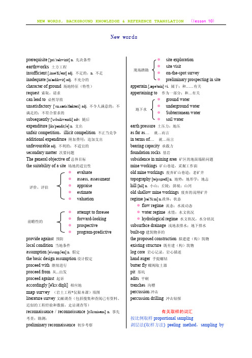
New wordsprerequisite ['pri:'rekwizit] n. 先决条件earthworks 土方工程insufficient [,insə'fiʃənt] adj. 不足的,n. 不足inadequate [in'ædikwit] adj. 不充分的character of ground 场地特征(特性)request 索取,请求can lead to 必然导致unsatisfactory ['ʌn,sætis'fæktəri] adj. 不令人满意的;不满足的;不符合要求的subsequently ['sʌbsikwəntli] adv. 随后expenditure [iks'penditʃə] n. 支出unfair competition,illicit compelition 不正当竞争additional expenditure 附加费用;追加支出unfavourable adj. 不利的;不适宜的secondary matter 次要问题The general objective of总体目标the suitability of a site 场地的适宜性z evaluatez assess, assessmentz appraisez estimatez valuationz attempt to foreseez forward-lookingz prospectivez program-predictive provide against 预防local condition 当地条件assumption [ə'sʌmpʃən] n. 假定the basic design assumption设计假定proceed with 继续进行proceed from 从...出发proceed against 起诉accordingly [ə'kɔ:diŋli] 相应地map survey (岩土工程*仅限本课)填图literature survey文献调查(包括搜集和查阅已有资料、近似的工程经验和数据,走访调查等)reconnaissance / reconnoissance [ri'kɔnisəns] n. 事先考查;勘测;preliminary reconnaissance 初步考察z site explorationz site visitz on-the-spot surveyz preliminary prospecting in site appertain [,æpə'tein] vi. 属于;和……有关appertaining to 作为一部分;和…有关z ground waterz underground waterz Subterranean waterz soil waterearth pressure 土压力;地压as far as… 就…而言in terms of… 就…而言bearing capacity 承载力foundation rocks 基岩subsidence in mining area 矿区的地面塌陷问题mine workings 矿山巷道,采掘工作面old mine workings 废弃矿山巷道;老矿井topography [tə'pɔɡrəfi] n. 地势;地形学;地志hill [hil] n. 小山;丘陵;斜坡;山冈old shallow mine workings 废弃的浅埋矿井regime [rei'ʒi:m] n.政体;状态z flow regime 流态;水流动态z water regime 水情;水文状况z hydrological regime 水文状况,水分状况subsurface drainage 浅地表排水;地下排水built-up建筑物多的the proposed construction 拟建建(构)筑物existing structure 既有建(构)筑物log core 岩心记录,岩心描述hand auger 手提螺钻butter fly蝶阀取土器pit 基坑adits 平硐trenches 沟槽percussion冲击percussion drilling 冲击钻探有关取样的词汇按比例取样proportional sampling剥层法(取样方法) peeling method,sampling by评价,评估前瞻性的现场踏勘地下水stripping沉落取样器drop sampler衬片取样器foil sampler重复取样repeated sampling, resampling地下取样subsurface sample地下水取样groundwater sampling冻结取样器cryogenic sampler对开式取样器split tube sampler多次取样multisampling二次取样subsample方格法(取样) quadrangle method分层取样stratified sampling固定活塞式取样器fixed piston sampler管式取样器tube sampler海底取样submarine sampling海底取样器kullenberg sampler盒式取样器(开斯顿取样器) kasten corer回转取样器rotary sampler井壁取样lateral coring井壁取样器side sampler; wall sampler井底取样器bottom-hole sample taker; bottom- hole sampler刻糟取样channel sampling刻槽取样法chip- channel method孔底取样器bottom sampler连续取样continuous sampling手动螺旋钻孔取样法auger sampling method泥泵取样器sample thief取岩心running coring取样sample collection; taking of sample; thief取样层位 sample horizon取样位置sample site取样法method of sampling取样格式 sampling dsign取样管bleeder / probe tube; sampling pepe取样厚度sampled thickness取样技术sampling technique取样|间隔sample interval; sample period取样间距interval of sampling取样流程 smpling flowsheet取样瓶 sample botlle取样器(深部) cheese tester取样枪sampling gun取样扰动sampling disturbance取样勺 sampling spoon 取样试验pick-test取样筒sampler barrel. sampling barrel. sampling tube取样系统sampling line取样钻进sample drilling取淤泥样sludge sampling双层取样double tube sampler双重岩心管取样器double tube core; barrelsampler 四分取样铲quartering shovel四分取样法quartering探槽取样pit sampling桶式取样方法barrel sampling外间隙比(取样器) outer clearance ratio无吊索取样管free-draining-fall corer系列取样serial sampling谢尔贝薄壁取样器Shelby tube sampler压力取样器pressure thief压入式取样器 jacker in sampler压人式取样简pressure-type core barrel液压活塞取样[土] hydraulic piston sampler移动式取样器moving machine sampler原地水取样器in-situ liquid sampler原状土取样器samplers for undisturbed samples真空取样器vacuum sampling tube真空岩心取样管vacuum corer重锤岩心取样gravity core sampling自返式取样管free-draining-fall core自由下落取样器free-draining-fall corer钻孔取样器messenger钻探(取样) drilling; bore; probe drilling; prospection drilling; exploralion drilling。
- 1、下载文档前请自行甄别文档内容的完整性,平台不提供额外的编辑、内容补充、找答案等附加服务。
- 2、"仅部分预览"的文档,不可在线预览部分如存在完整性等问题,可反馈申请退款(可完整预览的文档不适用该条件!)。
- 3、如文档侵犯您的权益,请联系客服反馈,我们会尽快为您处理(人工客服工作时间:9:00-18:30)。
河北工程大学毕业设计(论文)
achieved by resorting to a micropolar or Cosserat continuum description of the fractured rock mass, through the derivation of a generalized macroscopic failure condition expressed in terms of stresses and couple stresses. The implementation of this model is finally illustrated on a simple example, showing how it may actually account for such a scale effect. Problem Statement and Principle of Homogenization Approach The problem under consideration is that of a foundation (bridge pier or abutment) resting upon a fractured bedrock (Fig. 1), whose bearing
According to the yield design (or limit analysis) reasoning, the above structure will remain safe under a given vertical load Q(force per unit length along the Oz axis), if one can exhibit throughout the rock mass a stress distribution which satisfies the equilibrium equations along with the stress boundary conditions,while complying with the strength requirement expressed at anymounts to evaluating the ultimate load Q﹢ beyond which failure will occur, or equivalently within which its stability is ensured. Due to the strong heterogeneity of the jointed rock mass, insurmountable difficulties are likely to arise when trying to implement the above reasoning directly. As regards, for instance, the case where the strength properties of the joints are considerably lower than those of the rock matrix, the implementation of a kinematic approach would require the use of failure mechanisms involving velocity jumps
河北工程大学毕业设计(论文)
Failure Properties of Fractured Rock Masses as Anisotropic Homogenized Media
Introduction It is commonly acknowledged that rock masses always display discontinuous surfaces of various sizes and orientations, usually referred to as fractures or joints. Since the latter have much poorer mechanical characteristics than the rock material, they play a decisive role in the overall behavior of rock structures,whose deformation as well as failure patterns are mainly governed by those of the joints. It follows that, from a geomechanical engineering standpoint, design methods of structures involving jointed rock masses, must absolutely account for such ‘‘weakness’’ surfaces in their analysis. The most straightforward way of dealing with this situation is to treat the jointed rock mass as an assemblage of pieces of intact rock material in mutual interaction through the separating joint interfaces. Many design-oriented methods relating to this kind of approach have been developed in the past decades, among them,the well-known ‘‘block theory,’’ which attempts to identify potentially unstable lumps of rock from geometrical and kinematical considerations (Goodman and Shi 1985; Warburton 1987; Goodman 1995). One should also quote the widely used distinct element method, originating from the works of Cundall and coauthors (Cundall and Strack 1979; Cundall 1988), which makes use of an explicit finite-difference numerical scheme for computing the displacements of the blocks considered as rigid or deformable bodies. In this context, attention is primarily focused on the formulation of realistic models for describing the joint behavior. Since the previously mentioned direct approach is becoming highly complex, and then numerically untractable, as soon as a very large number of blocks is involved, it seems advisable to look for alternative methods such as those derived from the concept of homogenization. Actually, such a concept is already partially conveyed in an empirical fashion by the famous Hoek and Brown’s criterion (Hoek and Brown 1980; Hoek 1983). It stems from the intuitive idea that from a macroscopic point of view, a rock mass intersected by a regular network of joint surfaces, may be perceived as a homogeneous continuum. Furthermore, owing to the existence of joint preferential orientations, one should expect such a homogenized material to exhibit anisotropic properties. The objective of the present paper is to derive a rigorous formulation for the failure criterion of a jointed rock mass as a homogenized medium, from the knowledge of the joints and rock material respective criteria. In the particular situation where twomutually orthogonal joint sets are considered, a closed-form expression is obtained, giving clear evidence of the related strength anisotropy. A comparison is performed on an illustrative example between the results produced by the homogenization method,making use of the previously determined criterion, and those obtained by means of a computer code based on the distinct element method. It is shown that, while both methods lead to almost identical results for a densely fractured rock mass, a ‘‘size’’ or ‘‘scale effect’’ is observed in the case of a limited number of joints. The second part of the paper is then devoted to proposing a method which attempts to capture such a scale effect, while still taking advantage of a homogenization technique. This is