DAVID用户手册
DAVID用户手册
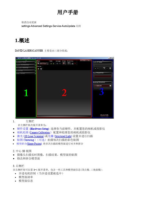
用户手册取消自动更新settings-Advanced Settings-Service-AutoUpdata关闭1.概述DA VID LASERSCANNER 主要是由三部分组成:1.左侧栏在左侧栏依次展开菜单为:∙硬件设置(Hardware Setup)选择你当前硬件,并配置您的相机或投影仪∙相机校准(Camera Calibration:)配置和校准您的相机或投影仪∙激光(3D Laser Scanning)或光栅(Structured Light)设置并进行扫描∙贴图(Texturing )(可选)拍摄每次扫描的彩色贴图∙模型拼合(Shape Fusion)将多次扫描的模型面进行对齐和拼合2.中心3D视图∙摄像头扫描实时图像,扫描结果,模型面的贴图∙修改和拼合模型面3.右侧栏在右侧栏你可以看3-4展开菜单,包含一些工具和模型面信息(顶点数.三角面数): ∙步进电机控制(当步进设置被选中)∙模型面清单∙模型面信息保存目录2.硬件设置通常你会选择一个自定义配置文件:1. 经典设置(Classic DA VID Setup):手持式线激光扫描。
2. 电动设置(Motorized DA VID Setup):步进电机控制线激光移动。
无需校准面板。
3. 光栅的灯光设置(Structured Light Setup):视频投影机。
无需校准面板。
另外,您可以定义自己的设置,如将扫描对象放置到步进电机控制的转盘等,此功能仍处于试验阶段。
3.激光扫描相机设置和校准在相机校准菜单中,你可以设置和校准您的相机。
校准意味着该软件可以知道的确切位置,视图方向,焦距,镜头畸变等,使用校准可以得到精确的扫描结果。
1.选择一个适合你扫描对象的校准图案尺寸。
左:校准图案太小;右:校准模式太大。
2.测量刻度长度(在校准面板的一侧)并输入值。
3.设置标定板,标定板必须是一个精确的90°角,扫描对象放置尽量靠后。
4.相机放置位置尽量与标定板图案中的横向4个空心环平行。
威士达操作手册2004版

一、VESDA烟雾报警系统原理简介前言VESDA烟雾报警系统是采用了当代先进的光电技术、网络通信技术和计算机技术制造的高技术产品,内含有多项专利保护的专门制造技术。
该系统独劈蹊径,改变了国内外传统火灾探测器的设计思路,其主要特点有:A 变被动等待为主动抽取空气样品。
传统的火灾探测器都是固定在房间的顶棚上或烟雾易到达之处,等待烟雾将其淹没并渗透到探测器内部时才能引起报警,这个过程花费的时间比较长,如同“守株待兔”。
而VESDA采用了高效抽气泵,通过分布到保护区的采样管网,主动抽取保护区的空气进行分析,并探测其中的烟雾含量,变被动等待为主动出击。
B 采用激光做光源,利用光散射原理探测烟雾,实现了极高的探测灵敏度和很宽的探测范围,两者结合体现出的优异的性能,这在传统火灾探测器中是没有的。
要求火灾探测器既有高灵敏度,又有宽的。
可调的探测范围,一直是消防业界追求的目标,因为消防业的最高的理念就是以防为主,制止火灾的发生。
VESDA系统采用高灵敏的探测器能测出保护区出现的早期微量烟雾,根据烟雾量的增长,发出早期予警、中期予警和火灾临界报警,使人们提早发现火灾苗头,将火灾扑灭于萌芽状态,不会酿成大火。
1. VESDA系统探测器的结构探测器由以下主要部件组成:1.1采样管入口总成----包括采样管入口、各管控制阀门及其驱动部件。
1.2高效抽气泵----采用无刷直流电机实现主动抽取空气。
可连续工作八年无须维护,该泵是专利保护产品。
1.3两级过滤器----空气流经过滤器,其中一级过滤后的空气送激光探测腔,测定其烟雾含量,另有一部分空气经二级精细过滤后喷射到激光腔内的光学元件表面,以维护其清洁,从而保证激光探测腔十年无需清洁和校正。
1.4激光探测腔----探测器的核心部件,由激光发射管、光束准直部件、消光器、散射光接收器等组成,是一受专利保护的免维护部件。
1.5电脑板----探测器的核心部件,由单片机、存储芯片、通讯芯片以及驱动器件等组成,担负信息的采集、处理和输出。
Wordalizer 1.5 用户手册说明书

wZ Wordalizerin InDesign CS4 / CS5 / CS6 / CCw Z2 . System requirements• Mac OS X 10.6 or later,or Windows XP / Vista / 7 / 8 (x86 or x64 editions).• CPU with a minimum clock rate of 3 GHz.• Main memory (RAM) of at least 4GB (8GB recommended).• 1000×800 pixel screen-resolution or greater.• Adobe InDesign CS4, CS5, CS5.5, CS6, or CC.3 . TRY vs. PRO versionYou can download a free tryout version of Wordalizer at: /blog/public/scripts/WordalizerTry.zip . It offers all the features of the PRO release, but it will automati-cally add on the word ‘Wordalizer’ into the final artwork.OOTEWe strongly encourage you to install and test the TRY version before you purchase the PRO license of the product. Always make sure that your system meets the requirements.The main dialog of Wordalizer has a very similar look-and-feel in both Mac OS and Windows environments. The followinglanguages are available (depending on your InDesign locale):▶ English (default) ▶ FrenchWordalizer both supportsCC 9.x and CC 2014w Z1 ) In InDesign, open the Scripts panel as follows:• CS4: Window ▶ Automation ▶ Scripts.• CS5, CS5.5, CS6, and CC: Window ▶ Utilities ▶ Scripts.3 ) You should now see a Scripts Panel folder. Drag WordalizerPro.jsxinto there. Congratulations, Wordalizer is now installed!MAC OS XRIGHT-CLICK CLICK DRAG INTOWINDOWSRIGHT-CLICKCLICKDRAG INTOw Zw Zw Z▶ Use last Wordalizer settingsSelect this option to reload the latest items and settingsused in Wordalizer disregarding the current context.This button is useful in particular when InDesign hasjust re-started.▶ Get the word list from the current cloudThis option is available when the active documentis a word cloud previously produced by Wordalizer.You can then reload its specific word list and settingsin order to either change some parameters (Update),or to create a new cloud based on the same model(Create).Select this option to quicly create a trial list based onrandom lorem-ipsum-fashioned words. By default,100 words are generated. You can change this numberfrom the preferences panel.2 .Specifying a languageWords captured from an InDesign document, book, or from theclipboard, can be automatically filtered and/or refined througha language-aware scanner. Its main purpose is to skip irrele-vant words, e.g. in English, ‘the,’ ‘is,’ ‘that,’ ‘by,’ etc. Wordalizermanages specific stop words for each supported language.w Zpressing Enter—if the existing weight already fits your needs.OOTE If you need to discard the current language, just clickthe active flag button to turn it off. Wordalizer will thenscan the entire text without removing stop words.w Zw Zvalues are entirely redistributed basing on that order.2 ) Click one of the following buttons:▶THEME100% StonesCHARACTERS100%0CLOUDBalance entry weightsDistribute numbers as linearly as possible—as if weights had toalign on a straight line.▶ LISTTHEME100%Stones100%Boost high entry weightsGradually increase high weights.▶ THEME100% StonesCHARACTERSBoost low entry weightsGradually decrease low weights.(where ¶ denotes a new line, spaces being optional.)OOTEThe whole word list cannot have more than 10,000 characters; each word item must have at most 50 characters; each weight must be a sequence of digits.3 ) Once your list is ready, copy it in the clipboard if you have used an external text editor, then go back to InDesign.4 ) Run Wordalizer and select either the source (get the list from the clipboard). OOTE The option “Detect word list” tends to slow down Wordalizer’sstartup. We recommend you turn it off if you don’t use it.Example ofweighted word list.w Zw ZCreate Close 20%0°0.2Create Close Update 20%0°0.2Myriad Pro Create CloseUpdate 20% Myriad Pro Regular FONT 4Create Update Stones20%00°0.2100%020%0°0.2100%0CLOUD 20%0°0.2100%0CLOUD 100%20%0°0.2Lemniscate Propeller Trefoil Hourglass Explosionw ZWordalizer PRO 1.508Licensedto:***********************wZ tectam 76borios 55issim 32sinctia 24dolorisi 82alicae 79magnima 76ipsant 72ulpa71hello world50Myriad Pro RegularFONT 3Myriad Pro RegularFONT 4Close 0°0.2Losange Create Close0°0.2Close0°0.2AstroidRectangularwordcloud based on the square pattern with W/H = 40%. (Theme: Museum .)w ZVerticality: 50 % + Shake angle: 10°Verticality: 50 % + Shake angle: 45°Verticality: 100 %w Zw Z Battleship Bloody Elves 2IPuppet Show Power Brickw Zw Z Native Theme Edited Themew Zw Ztion time. Lower values lead Wordalizer to run faster, but at the cost of raw approximation in computing and positioning vector artworks. Conversely, high precision will produce more consis-tent results but in a much greater delay.Increasing the precision may be effective whether the number of words to be processed does not exceed 300, and provided that very complex typefaces are not involved.The parser is the module by which Wordalizer scans a sourcetext and retrieve relevant words.• Change the “Min. frequency” value to eliminate low-fre-quency occurrences, often due to typos and/or hapax.• Turn on “Smart case” to allow the parser to detect case variants—such as InDesign vs. Indesign vs. INDESIGN—and then to keep the best form. If “Smart case” isSee Section 8. in“Manage yourWord List.”w Zand CC 2014. In particular it adjusts to InDesign dark theme if used—as shown below. In the case you change your interface preferences during a session, restart InDesign before you re-run Wordalizer.OOTE Wordalizer, of course, remains backwards compatible withInDesign CS4, CS5, and CS6 (Mac OS X and Windows).As Adobe is constantly updating InDesign CC, you may still experience issues that we cannot anticipate despite the many tests we perform. Please, feel free to report any new bug at ***********************.5 .Migrating from Wordalizer 1.25Wordalizer 1.25 for InDesign CS4 / CS5 is not supportedanymore. Although it can still be used in old environmentswithout causing conflict with the current version, we encourageyou to discover the features of Wordalizer 1.5.Note also that word clouds built from version 1.25 are fully rec-ognized by version 1.5, so you can easily update—and improve!—existing creations.Wordalizer’s main dialogas rendered in InDesign CCwhen a dark theme ischosen via Preferences ▶Interface ▶ Appearance.wZ Wordalizer 1.5w w w.i n d i s c r i p t s.c o mA plug-in for Adobe® InDesign® based on Adobe® ExtendScript and ScriptUI. Created and developed by Marc Autret. Designed by Dominique Chiron and Marc Autret. User Interface available in English and French.My very special thanks to Jonathan Feinberg (), Theunis de Jong (), Dominique Chiron () and Jean-Christophe Courte (). I also wish to thank the people who have helped improve and promote this produc t, in no partic ular order: Klaus Nordby, David Blatner (InDesignSecrets), Stéphane Baril (Adobe France), Loïc Aigon (Ozalto), Laurent Tournier (Indigrep), Cécile Mazin (Ac tuaLitté), Alexander Charc har (Smashing Magazine), Rinniee Ginsburg (Webgranth), Ingo Wilsinger, Jan Mirus—not forgetting those graphic designers, trainers, authors, and InDesign gurus who have all contributed at some level to the success of Wordalizer: Sandee Cohen and Diane Burns (authors of “Digital Publishing with Adobe InDesign”), Pariah Burke, Erica Gamet, Haeme Ulrich, Khaled Galal, Jennifer Blatz, Phillip Southgate and so many others!Main Product Page: /category/projects/WordalizerTryout version: /blog/public/scripts/WordalizerTry.zip Technical Support: ***********************Purchasing Wordalizer: /store/WDLZEnd User License Agreement: /pages/eulaTerms and Conditions of Sale: /pages/cgvCopyright Notice: /pages/copyrightThis manual, as well as the software documented in it, is released under license and may be used or copied only in accordance with the terms of that license. The content of this document is subject to change without notice. Every effort has been made to ensure that the information in this document is accurate. However, Indiscripts assumes no responsibility or liability for any error that may appear in this document. InDesign, the InDesign logos, are trademarks of Adobe Systems Incorporated.© Indiscripts, 2010-2015.All rights reserved. Made in France.。
DAVID三维扫描仪使用手册
这个视图显示了一个三维视图中的所有收集或加载扫描结果。 它可以让你 查看一个封闭的 360 度模型。
2
3、 右侧栏
在右边你可以看到展开的菜单,有如下信息和工具: 1. List of Scans 扫描清单 2. Scan Properties 扫描性能 3. Working Directory 工作目录
4、投影仪的设置 发货前投影仪已经进行了最优设置。我们建议不要对在投影仪显示屏上目录进行 任何更改。 你可以在屏目上进行恢复进行随时的重置操作: 1)选择“复位“ 2)注意一定要先关闭“autokeystone”,设置手动 Keystone 值为 0 更多详细信息,请参看投影仪的用户手册 3)、在 Window 扩展窗口里投影仪的设置(你个操作系统不同,将会有不同操作) 在桌面空白处点击鼠标右键,选择“像素”或“属性”(取决于你 window 的版 本)。图示
欢迎登陆华科网站 ,;欢迎加入德国 David 激光三维扫描仪中国地区技术交流 QQ 群,群号 297528366, 欢迎进入群共享下载并共享技术资料和扫描的作品。 欢迎登陆德国 David 公司网站
西安华科光电有限公司 2013 年 4 月
三维扫描仪使用手册
(简易版)
目录
一、 概述与软件介绍-----------1 二、 硬件安装-----------------4 三、 结构光扫描:-------------10 四、 纹理---------------------20 五、 形状融合-----------------21
前言
本手册是西安华科光电有限公司根据用户经常提的问题,以 及德国 David 公司提供的技术资料,做的简易版手册;本手册主要 针对初学用户,所以以图文并茂方式撰写;手册中有许多不足地方, 欢迎指正。本手册将陆续修正与更新,请关注。
EDP-CM-mbed Adapter Board 用户手册说明书

mbed ‘Command Module’– Adapter BoardRS-EDP-CM-mbed User ManualVersion 1.0129th June 2009Author: David GilesHitex UK Ltd1.0 Introduction2.0 Solder Link OptionsVB – Battery Voltage – J204DIP Pin 5 Option – J205DIP Pin 6 Option – J206DIP Pin 7 Option – J207DIP Pin 8 Option – J208DIP Pin 11 Option – J209DIP Pin 12 Option – J210DIP Pin 13 Option – J211DIP Pin 14 Option – J212DIP Pin 15 Option – J213DIP Pin 16 Option – J214DIP Pin 17 Option – J215DIP Pin 18 Option – J216DIP Pin 19 Option – J217DIP Pin 20 Option – J218DIP Pin 21 Option – J219DIP Pin 22 Option – J220DIP Pin 23 Option – J221DIP Pin 24 Option – J222DIP Pin 25 Option – J223DIP Pin 26 Option – J224DIP Pin 27 Option – J225DIP Pin 28 Option – J226DIP Pin 29 Option – J227DIP Pin 30 Option – J2283.0 Zero Ohm LinksVcc_CM - Command Module Voltage – R101VAGND - Analogue Ground – R10212VGND – 12V Power Ground – R1034.0 Software Support5.0 Schematic Circuit Diagram6.0 Board Components Layout1.0 IntroductionThe mbed development module is a very useful board that introduces a new way to write embedded firmware. Instead of having a C compiler license installed upon your machine the mbed unit makes use of a C Compiler installed on a virtual host. Your software and project are built within the framework of an HTML page. The compilation is done remotely on your behalf, and the resulting binary image file is transferred to you and stored on the mbed module. By rebooting the mbed module the new image is flashed into the hardware and the mbed module runs your application code.This is a superb w ay of gaining access to complex MCU’s like NXP’s ARM7 based devices without the requirement to purchase a full blown C compiler and debug tool. The mbed allows for writing of code, compiling of code and downloading to the target via very simple USB interface. The mbed platform comes currently as a 40 pin DIP module and software drivers for most of the hardware on the chip.This RS-EDP-CM-mbed adapter module is designed to remap the pin out of the mbed module to that of the RS-EDP platform. The adapter module also includes a mini SD Card interface and an SPI serial connection for a small graphics LCD.The RS-EDP platform is a system, which has been designed to utilise many different manufacturers’ microprocessors. To support ARMs mbed module, the RS-EDP platform uses an adapter board to connect between the RS-EDP baseboard and the mbed module. This is referred to as the EDP-CM-mbed module.The adapter module comes complete with a list of low level drivers that allow it to talk to the other module that form the RS-EDP system. The applications modules that are currently supported include analogue module, digital I/O module, communications module, brushed DC motor drive module MC1. A set of jumper and link options provide the user with several different ways to map the mbed to the RS-EDP.In an RS-EDP system there is usually one Command Module (CM) and one or more Applications Modules (AM) pluged in to the Base Board (BB). This adapter board is designed to hold the mbed module and as such it will be the ‘Command module’ for the system.The ‘C ommand Module’ in a system dictates whether the whole system is a 3.3V one or a 5.0V one. The module uses a 3.3V microprocessor and consequently the I/O is mostly 3.3V.To tell the rest of the system the mbed module is a 3.3V Command Module and not a 5.0V Command Module, the Vcc_CM line on the base board is connected to 3.3V by the tracking on the adapter board. This Vcc_CM is used as a reference by the other modules, such as the analogue module, to limit the output voltage to 3.3V. The command voltage line is also used by the #RESET circuit.The RS-EDP-CM-mbed daughter board remaps the I/O of the mbed module on to the backplane of the RS-EDP system. As there are quite a few dual function pins on the mbed module several link options have been made to accommodate the various options. Extensive use of the I2C capability is used to communicate to the application modules in the system.2.0 Solder Link OptionsMany of the options for the adapter/daughter board require a solder bridge to be made or a track bridge to be cut. The adapter board has been designed to be configured in the most popular setting by using track between the options, which will require cutting with a knife before making the alternate connection options.The options we have are as follows:VB – Battery Voltage – J204The mbed module has a VB input which is a battery backup voltage supply. You can connected this to the RS-EDP backup voltage rail or to the standard 3.3V supply via the link option. Note the base boards are supplied by default without the battery fitted.DIP Pin 5 Option – J205DIP Pin 6 Option – J206DIP Pin 7 Option – J207DIP Pin 8 Option – J208This pin has three functions. It primary function is for use as the chip select pin for the CNTRL SPI.DIP Pin 11 Option – J209DIP Pin 12 Option – J210DIP Pin 13 Option – J211DIP Pin 14 Option – J212DIP Pin 15 Option - J213DIP Pin 16 Option – J214DIP Pin 18 Option – J216DIP Pin 19 Option - J217DIP Pin 20 Option - J218DIP Pin 21 Option - J219DIP Pin 22 Option - J220DIP Pin 23 Option - J221DIP Pin 25 Option - J223DIP Pin 26 Option - J224DIP Pin 27 Option - J225DIP Pin 28 Option - J226DIP Pin 29 Option - J227DIP Pin 30 Option - J2283.0 Zero Ohm LinksVcc_CM - Command Module Voltage – R101R101 is used to connect the 3.3V rail to the Vcc_CM rail. This Vcc_CM rail is the command module voltage operating voltage rail. There is only one mbed module at present and it is based on an NXP 3.3V operation MCU. If however a 5V module appears then this link can be removed and replaced with a wire link to connect the 5V to the Vcc_CM. Under normal circumstance this resistor should remain fitted and it is the default options.VAGND - Analogue Ground – R102The VAGND and SGND lines are connected on the adapter module via the zero ohm link R102. For different grounding arrangement this resistor may be removed. The main user manual for the RS-EDP unit explains in more details about the ground options. The analogue module for example can have its analogue ground line connected to SGND also or instead of at this point.12VGND – 12V Power Ground – R103The 12VGND and SGND lines are connected on the adapter module via this zero ohm link R103. The default setting is to have this removed. See the circuit diagram for the base board module to see how the grounding scheme for the 12V works.4.0 Software SupportThe mbed Command Module for the RS-EDP platform is supported by all of the necessary software drivers to make driving of the platform very easy. All the low level support for the devices controlled by I2C for example have been written, as well as a test menu to exercise each of the modules independently of the others. This therefore provides working example of the code which will allow students and users to cut and paste various sections into their own applications.Each applications module has its own header file which provides the support for the functions that control it. Each module has its own set of high level functions that can be called to operate and control the hardware. This makes life a lot easier for the user, who can then spend most of his time working at the higher level application layer.The software has been packed up as a single ZIP file which can be imported into the mbed development environment by use of the ‘Project- Import’ feature.。
Automake中文手册

automake中文手册收藏GNU AutomakeFor version 1.3, 3 April 1998 David MacKenzie and Tom Tromey目录·介绍·通用性概念o通用操作o深度o严格性o统一命名机制o派生变量是如何命名的·一些实例软件包o一个简单的例子,从起点到终点o一个经典的程序o创建etags和ctags·创建`Makefile.in'·扫描`configure.in'o配置需求oAutomake能够识别的其它事情o自动生成的aclocal.m4o由Automake支持的Autoconf宏 o编写你自己的aclocal宏·顶层`Makefile.am'·创建程序和库o创建一个程序o创建一个库o对LIBOBJS和ALLOCA的特别处理 o创建一个共享库o创建一个程序时使用的变量o对Yacc和Lex的支持oC++和其它语言o自动de-ANSI-ficationo自动的依赖性(dependency)跟踪·其它派生对象o可执行的脚本o头文件o与体系结构无关(Architecture-independent)的数据文件o已创建的源代码·其它GNU工具oEmacs LispoGettextoGuileoLibtooloJava·创建文档oTexinfooMan手册·安装了些什么·清除了些什么·需要发布哪些文件·对测试套件(test suites)的支持·改变Automake的行为·其它规则o与etags之间的界面o处理新的文件扩展名·条件(Conditionals)·--gnuand --gnits的效果·--cygnus的效果·什么时候Automake不够用·发布`Makefile.in'·未来的某些想法·索引@dircategory GNU admin @direntry * automake: (automake). Making Makefile.in's @dircategory Individual utilities @direntry * aclocal: (automake)Invoking aclocal. Generating aclocal.m4Copyright (C) 1995, 96 Free Software Foundation, Inc.这是GNU Automake文档的第一版,并且是针对GNU Automake 1.3的。
维萨拉中文手册HMT360
维萨拉 HUMICAP® HMT360 系列温湿度变送器
M010056ZH-G
出版人 VAISALA Oyj P.O. Box 26 FIN-00421 Helsinki FINLAND
电话(国际长途): 传真:
(+358 9) 894 91 (+358 9) 894 9227
欢迎访问我公司互联网站:. © Vaisala 2007
未经版权持有人的事先书面许可,不得以任何形式或者任何手段,无论是电子的还是 机械的ห้องสมุดไป่ตู้其中包括影印),对本手册任何部分进行复制,也不得将其内容传达给第三 方。
本说明手册内容如有变更,恕不另行通知。
此操作手册由英文版本翻译而得,如有不妥之处,敬请参照英文操作手册。
第 1 章 ____________________________________________________________________________ 概述
第4章
操作 ...............................................................................................................37 当地显示 ...................................................................................37 开关ON/OFF ........................................................................ 38 HMT360 带显示 ...................................................................38 HMT360 不带显示................................................................38 DIP开关功能 ........................................................................38 显示/按键命令 ......................................................................40 设置计算用的压力 ................................................................ 40 选择输出参数 .......................................................................40 显示屏上半部分 ...................................................................40 显示屏下半部分 ...................................................................41 选择模拟输出 .......................................................................41 调整模拟输出量程 ................................................................ 42 串口界面 ...................................................................................43 设定通讯参数 .......................................................................44 设置模拟输出 .......................................................................44 ASEL 选择模拟输出.............................................................44 S 调整模拟输出量程 ............................................................45 调整命令 ..............................................................................46 CRH相对湿度调整 ...............................................................46 CT温度校准 .........................................................................46 输出命令 ..............................................................................47 ITEST测试模拟输出 ............................................................. 47 SEND输出测量值................................................................. 48 R激活连续输出 ....................................................................48 S停止连续输出..................................................................... 48 INTV设定输出时间间隔 .......................................................48 PRES设定用于计算的环境压力 ...........................................49 FILT输出过滤 ....................................................................... 49 变送器复位........................................................................... 50 RESET变送器复位............................................................... 50
David Clark Series 3800 汽车通讯系统说明书
S E R I E S 3800V E H I C L E I N T E R C O M S Y S T E MW W W .D A V I D C L A R K .C O MA vehicle intercom system that provides a solution for enhanced safety,hearing protection, and clear communication.Series 3800 Vehicle Intercom Systems are engineered to solve the problem of communicating in high noise environments, especially those associated with emergency operations during call response and at the scene. They enable personnel on the apparatus to communicate clearly,without interference from vehicle noise, including sirens.They have the option of connecting to mobile radios,allowing all personnel to listen to the radio and selected stations to transmit over the radio.Modular Design - Rugged and serviceable. Reduces costly downtime on installation or module replacement.Very cost effective.Weather Tight - All system components are designed for use in severe weather. All modules are manufactured using rugged, heavy gauge, polycarbonate (-80˚F to +212˚F)housings with integral mounting feet.Industry Standard- In use worldwide by emergency service departments, the Series 3800 Vehicle Intercom System isan extremely versatile “workhorse” able to accommodate most vehicle and system design requirements.Versatile - Can be installed on Fire Apparatus,Ambulances, Rescue Boats, Utility and Construction vehicles of all types. If it rolls,floats or flies... or not, David Clark Company has a solution to help you cope with high noise environments.U3801 REMOTE HEADSET STATIONThis simple headset station is used to expand the system, usually at the end of a series of headset stations. There are no output connectors to connect additional modules. It has one headset jack and a listen level control. Use where radio transmit is not required. 3-1/4”L x 4-3/4”W x 3”D.U3802 REMOTE HEADSET STATIONExpands the system beyond the master station. Contains one headset jack and listen level control, system input connector and two system output connectors. Provides a path for “daisy-chaining” to additional headset stations.5-3/8”L x 4-1/4”W x 3”D.U3800 MASTER STATIONThe “heart” of the system. One each is required per system. The U3800 will accommodate two headsets and should be placed where radio transmit function is not required. Adjusts automatically for 12 or 24VDC power source. Contains system on/off, master volume control, two headset jacks with listen level controls, power inputconnector and two remote output connectors.Draws less than 600 milliampere current.8-1/4”L x 5-3/4”W x 4-3/4”D.Note: All Radio Interface Headset Station Modules provide radio transmit isolation with the exception of the U3810 and the U3812.U3810 RADIO INTERFACEMODULEAdds the transmit and receive functions ofa mobile radio to the David Clark Series3800 Intercom System. Use of this moduleis recommended for two- or three-personsystems only. The U3810 has one radiopush-to-talk (PTT) switch, one systeminput connection, one radio inputconnection and two connectors for optionalremote PTT.5-1/4”L x 5-1/4”W x 2-3/4”D.Note: All intercom traffic is transmitted when PTTis engaged.U3811 RADIO INTERFACEMODULEProvides isolated radio transmit function forone headset and radio receive function forall users. Contains one radio PTT switch,one headset jack and listen level control,one system input connection and one radioinput connection.5-1/4”L x 3-5/8”W x 3-1/16”D.U3812 DUAL RADIO INTERFACEMODULEDesigned to connect two separate radiosto a David Clark Series U3800 IntercomSystem. The priority reception featureenables the user to select which radio’sreceive audio will have precedence bysimply connecting the priority radio to thepriority radio input connector. Containsone C38-XX system connector, twoconnectors for radio input (C3821), andtwo connectors for optional remote PTTs.8-1/2”L x 5-3/4”W x 4-1/8”D.Note: All intercom traffic is transmitted when PTTis engaged.U3803 REMOTE JUNCTIONMODULEA passive module containing fouridentically wired connectors for expandingthe number of headset stations utilized inthe system. A U3803 may be added to thesystem wherever C38-XX Jumper Cords areto be interconnected.5-1/4”L x 5-1/4”W x 2-3/8”D.U3805 RADIO CORD JUNCTIONMODULERecommended for systems utilizing two ormore radio interface headset stations. It isa passive module that permits multipleSeries 3800 Radio Interface Modules(a maximum of four) to be connected toone radio. The U3805 provides one outputto a mobile radio, one primary input from aSeries 3800 Radio Interface Module, andthree secondary inputs from Series 3800Radio Interface Modules.6-3/4”L x 5-1/4”W x 2-3/8”D.Note: With modifications, the U3805 also accepts inputfrom model C3019 Utility Radio Adapters.U3806 DUAL HEADSETINTERCOM STATIONExpands the system beyond the masterstation. Contains two headset jacks,each with listen level control, systeminput connector and two system outputconnectors. Provides a path for “daisy-chaining” to additional headset stations.6-3/4”L x 4-1/4”W x 3-1/16”D.U3813 RADIO INTERFACE MODULE (use with H7042 Headset only)Is designed to combine the transmit/receive functions of a mobile radio with the David Clark Series 3800 Intercom System. The U3813 contains one headset jack, one listen level control, one PTT switch, one radio input connector (C3821), two intercom connectors (C38-XX) and a remote PTT connector that allows the use of an optional Footswitch (40071G-04) or other remote PTTs.7”L x 4-1/3”W x 3-1/8”D.Note: The U3813 Radio Interface Module and the U3817Remote Headset Station are the only Series 3800 Modules that accept the H7042 Headset. The H7042 Headset is designed for use with certain older portable radios and requires a David Clark Company 7000 Series Adapter specific to the portable radio brand and model.U3814 MULTI RADIO INTERFACE MODULEIs designed to connect up to four radios to a David Clark Series 3800 Intercom System.Contains one headset jack with listen level control, one radio volume control, one four-position radio select switch, one radio PTT, four connectors for radio input(C3821), two system connectors (C38-XX),one connector for speaker cut-out option,and one connector for optional C3023 Belt Station, Footswitch (40071G-04) or other remote PTT. A red LED indicator over the PTT switch will light, indicating transmission over the selected radio.Provides isolated radio transmit function for one headset and radio receive function for all users on the system.8-1/2”L x 5-1/4”W x 3-1/8”D.U3815 RADIO INTERFACE MODULECombines the transmit/receive functions of a mobile radio with the David Clark Series 3800 Intercom System. This module has one headset jack with listen level control,one PTT switch, one radio input connector (C3821), two intercom connectors (C38-XX) and one connector allowing use of an optional Footswitch (40017G-04) or other remote PTT.7”L x 4-1/3”W x 3-1/8”D.U3815A RADIO INTERFACE MODULESame features as U3815, but remote PTT connection will accept 40071G-04Footswitch or C3023 Belt Station. 7”L x 4-1/3”W x 3-1/8”D.U3816 DUAL RADIO INTERFACE HEADSET STATIONThe standard choice when connecting the 3800 Intercom System to two radios.Provides two connectors to mobile radios (C3821), two intercom system connections (C38-XX), one headset jack with listen level control, two radio receive levelcontrols, two PTT switches and two remote PTT connections (corresponding to each of the mobile radios). The remote PTT connectors will accept C3023 Belt Stations or Footswitches (40071G-04).8-1/2”L x 5-1/4”W x 3-1/8”D.U3817 REMOTE HEADSET STATION (use with H7042 Headset only)Expands the system beyond the master station. Contains one headset jack and listen level control, system input connector and two system output connectors. Provides a path for “daisy-chaining” to additional headset stations.5-3/8”L x 4-1/4”W x 3”D.Note: The U3813 Radio Interface Module and the U3817 Remote Headset Station are the onlySeries 3800 Modules that accept the H7042 Headset. The H7042 Headset is designed for use with certainolder portable radios and requires a David Clark Company 7000 Series Adapter specific to the portable radio brandand model.C3820 POWER CORDConnects U3800 to power source, 20-foot,two-conductor shielded cable with two-socket MS connector. Power end has stripped and tinned conductors. Fuse Kit included.C3821 RADIO CORDConnects radios to radio interface module.21-foot, six-conductor shielded cable with six-pin MS connector. Radio end has stripped and tinned conductors.C38-12, -25, -50, -75, -100 JUMPER CORDSConnects modules and U3800. Four-conductor shielded cable with four-pin MS connectors on each end. (Number after dash indicates length in feet.)C3019 UTILITY RADIO ADAPTERProvides interface between any David Clark Series 3000 Noise-attenuating Headset and most mobile radios. Ideal for radio interface at the pump panel. Has radio PTT switch and listen level control. A 15-foot (extended) coil cord allows increased mobility.18352G-16 CONNECTOR KITAccepts C3019 Utility Radio Adapter. Use as panel or bulkhead mount. A Protector Cap (13238P-01) is recommended. Six-conductor cable is available. (Order per foot - P/N 09271P-13.)C3023 BELT STATIONProvides intercom and radio transmit capability. Has radio PTT switch and listen level control. May be used with U3814, U3815A, & U3816. A 15-foot (extended) coil cord allows increased mobility.40071G-04 FOOTSWITCHMay be used with U3813, U3814, U3815,U3815A & U3816. (Option for Remote Push-to-Talk with Mobile Radios)40107G-01 RADIO INTERFACE ADAPTERUse if adapting to a Motorola Spectra,Syntor X9000, or Maratrac w/A7 heads.Mates with five-pin connector 09227P-81.40666G-01 HEADSET ADAPTERAllows 6000 and 4200 Series Headsets to be used with 3800 System Headset Stations. (Exception: do not use withU3813 or U3817).*Consult factory before using in system.Only headset plugged into headset station will be heardOver-the-head-styleMODEL H3492HEADSET/MICROPHONESingle Ear.• Microphone: Noise-cancelling M-7A Electret (nominal 50 ohm).• Boom: Hybrid boom assembly for precise microphone positioning.• Rotates for left or right side placement.• Earphone: Lightweight dynamic (nominal 300 ohm) wired in series.• Cord: Shielded 4-conductor, 5’Coil. • Plug: PJ-051.• Microphone on/off button.MODEL H3432HEADSET/MICROPHONEOver-the-Head Style.• Microphone: Noise-cancelling M-7A Electret (nominal 50 ohm).• Boom: Hybrid boom assembly for precise microphone positioning.• Rotates for left or right side placement.• Earphone: Lightweight dynamic (nominal 300 ohm) wired in series.• Cord: Shielded 4-conductor, 5’Coil. • Plug: PJ-051.• Microphone on/off button.• NRR: 23dB.SERIES 3400 HEADSETSBehind-the-head-styleBehind-the-head-styleOver-the-head-styleMODEL H3442HEADSET/MICROPHONEDesigned to be worn under helmets or safety caps.• Microphone: Noise-cancelling M-7A Electret (nominal 50 ohm).• Boom: Hybrid boom assembly for precise microphone positioning.• Rotates for left or right side placement.• Earphone: Lightweight dynamic (nominal 300 ohm) wired in series.• Cord: Shielded 4-conductor, 5'Coil.• Plug: PJ-051.• Microphone on/off button.• NRR: 23dB.MODEL H7042HEADSET/MICROPHONEDesigned to be worn under helmets or safety caps.• Microphone: Dynamic Noise-cancelling M101/DC (nominal 7 ohm).• Boom: Has three different adjustment points for perfect microphoneplacement. Can be rotated to position microphone on left or right side.• Earphone: Lightweight dynamic (nominal 19 ohm) wired in parallel.• Cord: Shielded 4-conductor, 5’Coil.• Plug: U-174/UNOTE:If a headset compatible with portable radios (Series 7000,low impedance) is to be integrated into the 3800 System, the U3817 Remote Headset Station and the U3813 Radio Interface MODEL H3441HEADSET/MICROPHONESingle receiver, slotted dome. Designed to be worn under helmets or safety caps.• Microphone: Noise-cancelling M-7A Electret (nominal 50 ohm).• Boom: Hybrid boom assembly for precise microphone positioning.• Rotates for left or right side placement.• Earphone: Lightweight dynamic (nominal 300 ohm) wired in series.• Cord: Shielded 4-conductor, 5’Coil.• Plug: PJ-051.• Microphone on/off button.MODEL H6040HEADSET/MICROPHONE• Microphone: Noise-cancelling M-77 Electret.• Boom: Full flex for precisemicrophone positioning. Can be positioned for left or right side microphone placement.• Earphone: Lightweight dynamic (nominal 275 ohm) wired in parallel.• Cord:Shielded4-conductor, 36”straight.• Plug: U-174/U.NOTE:If a Series 6000 Headset is to be integrated into the 3800System, an adapter, P/N 40666G-01, must be used. Not to be used with the U3817 Remote Headset Station or the U3813 Radio Interface Module.Other Styles AvailableBehind-the-head-styleBehind-the-head-styleOther Styles AvailableSERIES 6000HEADSETSERIES 7000HEADSETMARINE INTERCOM SYSTEMSDISTRIBUTED BY:SERIES 3800 Vehicle Intercom SystemSpecification FormUse this drawing as a guide for specifying the David Clark CompanySeries 3800 Vehicle Intercom System.The following questions need to be answered:• Which positions to have intercom and radioreceive?(Indicate with R placement on the vehicle layout)• Which positions to have intercom radio transmit andreceive?(Indicate with T/R placement on the vehicle layout)• How many mobile radios?(Indicate brand & model)__________________________________________________________________________________________________________________________________________________________________________________________Please include:Name:______________________________________________________Title:________________________________________Firm:______________________________________________________Address:____________________________________________________City______________________________State:____Zip:__________Phone:____________________________Fax:____________________E-Mail:____________________________________________________Please return to: FAX: 508-753-5827SERIES 3800 Vehicle Intercom SystemSpecification FormUse this drawing as a guide for specifying the David Clark CompanySeries 3800 Vehicle Intercom System.The following questions need to be answered:• Which positions to have intercom radio transmit and receive?(Indicate with T/R placement on the vehicle layout) i.e. Driver, Officer• Which positions to have intercom and radio receive?(Indicate with I/R placement on the vehicle layout) i.e. Jump Seats• Which positions to have radio transmit and receive-no intercom?(Indicate with R placement on the vehicle layout)i.e. Pump Panel• How many mobile radios?(Indicate brand & model)__________________________________________________________________________________________________________________________________________________________________________________________Please include:Name:______________________________________________________Title:________________________________________Firm:______________________________________________________Address:____________________________________________________City______________________________State:____Zip:__________Phone:____________________________Fax:____________________E-Mail:____________________________________________________Please return to: FAX: 508-753-5827。
DAVID液压设备VAG1389操作手册
DA VID液压设备V AG1389操作手册MATRA全球机械制造MATRA制造有限责任公司邮编 111351 60048 法兰克福/缅茵电话:(069) 4016—0传真:(069) 4016225目录章节页码1概述 32DA VID泵 43单活塞手动泵5,64多级活塞手动泵7,8,9,105脚操纵116液压油127高压软管128液压装置(装置)139管接头1410压力表15,1611连接件1712附录:备件标识本说明书是本公司的财富。
它包括技术工艺说明,未经同意,特别是竞争企业未经许可,禁止以各种方式全部或部分复制,或用于商业目的。
(参见1901年06月19日颁布的版权法和1909年06月01日颁布的不正当竞争法)关于工程单位换算的说明根据1970年7月2日实施的“测量工程单位法”和依据德国工业标准DIN1301下述单位符号可应用。
力牛顿=N=1kgm/s2压力巴=bar=10N/cm2单位符号举例1概述DA VID液压装置的基本单元由一个油泵(手动、脚蹋或电动泵)和一条或多条高压软管组成,高压油管通过管接头与液压工作油缸(压、拉或者拉—压头、传感器工作头、双柱压力装置等)连接。
油泵和液压装置设计最大工作压力都为625bar。
(特制液压装置工作压力较高。
)与油泵的安装无关,液压装置可在安装工件的任意位置,或者置于在机器和设备内。
绝大多数液压装置用固定螺纹联接在液压缸上。
对于从100~1000kN的不同液压装置预先设定施压位置,通过施压位置,使用简单的工具,安装盛开个完整的压力机械。
选择其它特制装置和配件可以组成通用液压装置。
利用不同的控制仪表,可以大大地拓宽其应用领域。
DAVID压力机械的尺寸和技术参数可从本公司详细的DAVID样本简介查阅。
DAVID液压机械的使用不需要特殊的知识和技能。
但应注意下列操作规范,以避免干扰和产生故障。
使用DAVID压力机械应遵守一般的操作使用要求和相应的安装调试步骤。
DAVID使用方法介绍
DAVID使用说明文档一、DAVID简介DAVID (the Database for Annotation,Visualization and Integrated Discovery)的网址是/。
DAVID是一个生物信息数据库,整合了生物学数据和分析工具,为大规模的基因或蛋白列表(成百上千个基因ID或者蛋白ID列表)提供系统综合的生物功能注释信息,帮助用户从中提取生物学信息。
DAVID这个工具在2003年发布,目前版本是v6.7。
和其他类似的分析工具,如GoMiner,GOstat等一样,都是将输入列表中的基因关联到生物学注释上,进而从统计的层面,在数千个关联的注释中,找出最显著富集的生物学注释。
最主要是功能注释和信息链接。
二、分析工具:DAVID需要用户提供感兴趣的基因列表,在基因背景下,使用提供的分析工具,提取该列表中含有的生物信息。
这里说的基因列表和背景文件的选取对结果至关重要。
1.基因列表:这个基因列表可能是上游的生物信息分析产生的基因ID列表。
对于富集分析而言,一般情况下,大量的基因组成的列表有更高的统计意义,对富集程度高的特殊Terms有更高的敏感度。
富集分析产生的p-value在相同或者数量相同的基因列表中具有可比性。
DAVID对于基因列表的格式要求为每行一个基因ID或者是基因ID用逗号分隔开。
基因列表的质量会直接影响到分析结果。
这里定性给出好的基因列表应该具有的特点,一个好的基因列表至少要满足以下的大部分的要求:(1)包含与研究目的相关的大部分重要的基因(如标识基因)。
(2)基因的数量不能太多或者太少,一般是100至10000这个数量级。
(3)大部分基因可以较好的通过统计筛选,例如,在控制组和对照组样品间选择显著差异表达基因时,使用的t-test标准:fold changes >=2 && P-values <=0.05。
(4)大部分是上下调的基因都涉及到特定的某一生物过程,而不是随机的散布到所有可能的生物过程中。
- 1、下载文档前请自行甄别文档内容的完整性,平台不提供额外的编辑、内容补充、找答案等附加服务。
- 2、"仅部分预览"的文档,不可在线预览部分如存在完整性等问题,可反馈申请退款(可完整预览的文档不适用该条件!)。
- 3、如文档侵犯您的权益,请联系客服反馈,我们会尽快为您处理(人工客服工作时间:9:00-18:30)。
用户手册
取消自动更新
settings-Advanced Settings-Service-AutoUpdata关闭
1.概述
DA VID LASERSCANNER 主要是由三部分组成:
1.左侧栏
在左侧栏依次展开菜单为:
∙硬件设置(Hardware Setup)选择你当前硬件,并配置您的相机或投影仪∙相机校准(Camera Calibration:)配置和校准您的相机或投影仪
∙激光(3D Laser Scanning)或光栅(Structured Light)设置并进行扫描
∙贴图(Texturing )(可选)拍摄每次扫描的彩色贴图
∙模型拼合(Shape Fusion)将多次扫描的模型面进行对齐和拼合
2.中心3D视图
∙摄像头扫描实时图像,扫描结果,模型面的贴图
∙修改和拼合模型面
3.右侧栏
在右侧栏你可以看3-4展开菜单,包含一些工具和模型面信息(顶点数.三角面数):
∙步进电机控制(当步进设置被选中)
∙模型面清单
∙模型面信息
∙保存目录
2.硬件设置
通常你会选择一个自定义配置文件:
1. 经典设置(Classic DA VID Setup):手持式线激光扫描。
2. 电动设置(Motorized DA VID Setup):步进电机控制线激光移动。
无需校准面板。
3. 光栅的灯光设置(Structured Light Setup):视频投影机。
无需校准面板。
另外,您可以定义自己的设置,如将扫描对象放置到步进电机控制的转盘等,此功能仍处于试验阶段。
3.激光扫描
相机设置和校准
在相机校准菜单中,你可以设置和校准您的相机。
校准意味着该软件可以知道的确切位置,视图方向,焦距,镜头畸变等,使用校准可以得到精确的扫描结果。
1.选择一个适合你扫描对象的校准图案尺寸。
左:校准图案太小;右:校准模式太大。
2.测量刻度长度(在校准面板的一侧)并输入值。
3.设置标定板,标定板必须是一个精确的90°角,扫描对象放置尽量靠后。
4.相机放置位置尽量与标定板图案中的横向4个空心环平行。
在相机菜单中设置分辨
率和颜色格式,设置曝光,亮度,对比度等,最重要的设置为“曝光”。
设置相机的焦点,将扫描对象放置在扫描对象应该涵盖大部分的图像高度。
将相机支持自动功能关闭,如自动对焦,自动曝光,自动亮度,人脸跟踪等。
5.暂时移走扫描对象,点击“校准(Calibrate)”。
如校准失败,调整图像设置(主要是亮
度和对比度),调节相机镜头.将标记点调制最清晰,移动标定板,将图中6个空心环出现在视频中.校准成功后.勿移动标定板.
三维激光扫描
打开三维激光扫描菜单。
相机设置自动切换到你上次的扫描设置(或默认值),将扫描对象放置正确位置后,使环境光尽量暗,打开线激光,在软件实时画面中查看,并尝试移动激光与扫描对象的距离或调整激光微调,尽可能将激光线调整到最细。
最佳图像:
彩色相机黑白相机
选择激光类型(Laser color)后,单击开始键(Strar),手持或者电动将激光由上至下,或者由下至上缓慢移动,约每分钟1/4转,此时注意激光线与相机的角度在15 – 45 之间。
如效果不佳,可重复扫描。
扫描操作过程中,如果软件是无法准确地跟随激光线,在《中心3D视图》窗口左下方会显示提示消息,(例如,未检测到XX)。
并调整激光(角度,方位,距离,旋转速度等)。
当完成后,关闭激光线或停止移动,然后单击停止键(Stop)。
待软件计算完成后将得到结果,你可以使用插补(interpolation),
均值平滑(Smooth average),中值平滑(Smooth median)使结果更理想。
完成后可将结果添加到软件列表(Add to List)或保存(Save As)。
4.光栅扫描
5贴图
此菜单功能抓取图像的贴图(彩色相机)。
抓取时使环境光明亮些。