涡旋压缩机英文论文(翻译)
涡旋压缩机实习报告

涡旋压缩机实习报告英文回答:Internship Report on Scroll Compressor.Introduction:During my internship at XYZ Company, I had the opportunity to work with scroll compressors. In this report, I will share my experiences and knowledge gained duringthis period.Description of Scroll Compressor:A scroll compressor is a type of positive displacement compressor that uses two spiral-shaped scrolls to compress the refrigerant or gas. It is widely used in airconditioning systems, heat pumps, and refrigeration systems. The main advantage of a scroll compressor is its high efficiency and low noise level.My Responsibilities:During my internship, I was responsible for assisting the engineers in the assembly and testing of scroll compressors. I learned about the different components of the compressor, such as the fixed scroll, orbiting scroll, and discharge port. I also gained hands-on experience in troubleshooting and maintenance of the compressors.Challenges Faced:One of the challenges I faced was understanding the complex design and operation of the scroll compressor. It took me some time to grasp the concept of how the scrolls interact with each other to compress the gas. However, with the guidance of the engineers and my own research, I was able to overcome this challenge.Learning Experience:Working with scroll compressors has been a valuablelearning experience for me. I have gained a deeper understanding of the principles of thermodynamics and fluid mechanics. I have also learned about the importance of precision and attention to detail in the assembly and testing processes.Example:One of the key lessons I learned was the importance of proper lubrication in scroll compressors. During one of the tests, we noticed that the compressor was making unusual noises. Upon inspection, we found that the lubrication oil level was low. After adding the required amount of oil, the compressor operated smoothly. This experience taught me the significance of regular maintenance and the impact it has on the performance of the compressor.Conclusion:Overall, my internship experience with scroll compressors has been rewarding. I have gained practical knowledge and skills that will be beneficial for my futurecareer in the field of mechanical engineering. I amgrateful for the opportunity to work with experienced professionals and apply theoretical concepts to real-world applications.中文回答:涡旋压缩机实习报告。
谷轮涡旋压缩机 英文

谷轮压缩机--中国营销中心:4000-500-856 官网: 谷轮压缩机--中国营销中心 4000-500-856 官网:谷轮压缩机--中国营销中心:4000-500-856 官网:谷轮压缩机--中国营销中心:4000-500-856 官网:1ACopeland is the recognized leader in the development of advanced compressor technology.1B 谷轮压缩机--中国营销中心:4000-500-856 官网:谷轮压缩机--中国营销中心:4000-500-856 官网:2APERFORMANCE NOMINALS50 HERTZR22SINGLE PHASE220-1-50 TEST VOLTAGECAPACITYENERGY EFFICIENCY RATINGRATING MOTOR MODELAMPERESBTU KCAL BTUH KCALH WATTS CONDITIONWATTSWATTSHOURHOURMOTOR WATTS MOTOR WATTSMOTOR WATTSA 183004610536017308.010.6 2.7 3.1ZR22K3-PFJB 182004590533017308.010.5 2.7 3.1C 21500542063001190 5.718.1 4.6 5.3A 204005140598019209.210.6 2.7 3.1ZR24K3-PFJ B 202005090592019209.210.5 2.7 3.1C 24200610070901310 6.318.5 4.7 5.4A 219005520642020109.510.9 2.7 3.2ZR26K3-PFJ B 217005470636020109.510.8 2.7 3.2C 25800650075601400 6.818.4 4.6 5.4A 2380060006970219010.410.9 2.7 3.2ZR28K3-PFJ B 2360059506910219010.410.8 2.7 3.2C 282007110826015107.418.7 4.7 5.5A 2540064007440233011.110.9 2.7 3.2ZR30K3-PFJ B 2520063507380233011.110.8 2.7 3.2C 302007610885016307.918.5 4.7 5.4A 2670067307820243011.811.0 2.8 3.2ZR32K3-PFJ B 2650066807760243011.810.9 2.7 3.2C 315007940923017008.718.5 4.7 5.4A 2830071308290254012.111.1 2.8 3.3ZR34K3-PFJ B 2810070808230255012.111.0 2.8 3.2C 333008390976017308.519.2 4.8 5.6A 3040076608910271013.111.2 2.8 3.3ZR36K3-PFJ B 3020076108850272013.111.1 2.8 3.3C 3600090701050018709.419.3 4.9 5.6A 3360084709840299014.711.2 2.8 3.3ZR40K3-PFJ B 3330083909760300014.711.1 2.8 3.2C 39400993011500207010.819.0 4.8 5.6A 35300890010300314015.211.2 2.8 3.3ZR42K3-PFJ B 35000882010300315015.211.1 2.8 3.3C 415001050012200216010.919.2 4.9 5.6A 38500970011300337016.411.4 2.9 3.4ZR45K3-PFJ B 38200963011200338016.411.3 2.8 3.3C 450001130013200237012.119.0 4.8 5.6A 397001000011600345016.811.5 2.9 3.4ZR47K3-PFJ B 39400993011500346016.811.4 2.9 3.3C 465001170013600242012.619.2 4.8 5.6A 408001030012000362017.611.3 2.8 3.3ZR48K3-PFJ B 405001020011900363017.611.2 2.8 3.3C 478001200014000252013.519.0 4.8 5.6A 575001450016800512024.511.2 2.8 3.3ZR68KC-PFJB 570001440016700513024.511.1 2.8 3.3C673001700019700367018.218.34.65.43BPERFORMANCE NOMINALS50 HERTZR22THREE PHASETEST VOLTAGECAPACITYENERGY EFFICIENCY RATINGRATING MOTOR MODELAMPERES*BTU KCAL BTUH KCALH WATTS CONDITIONWATTSWATTSHOURHOURMOTOR WATTS MOTOR WATTSMOTOR WATTSA 18300461053601770 5.5/3.210.3 2.6 3.0ZR22K3-TF5/DB 18200459053301770 5.5/3.210.3 2.6 3.0C 21500542063001170 4.3/2.518.4 4.6 5.4A 20400514059801920 6.0/3.510.6 2.7 3.1ZR24K3-TF5/DB 20200509059201920 6.0/3.510.5 2.7 3.1C 24200610070901250 4.7/2.719.4 4.9 5.7A 21900552064202010 6.6/3.810.9 2.7 3.2ZR26K3-TF5/DB 21700547063602010 6.6/3.810.8 2.7 3.2C 25800650075601360 5.0/2.919.0 4.8 5.6A 23800600069702150 6.9/4.011.1 2.8 3.2ZR28K3-TF5/DB 23600595069102150 6.9/4.011.0 2.8 3.2C 28200711082601450 5.4/3.119.4 4.9 5.7A 254006400744022907.3/4.211.1 2.8 3.2ZR30K3-TF5/DB 252006350738022907.3/4.211.0 2.8 3.2C 30200761088501540 5.5/3.219.6 4.9 5.7A 267006730782024307.6/4.411.0 2.8 3.2ZR32K3-TF5/DB 265006680776024307.6/4.410.9 2.7 3.2C 31500794092301640 5.9/3.419.2 4.8 5.6A 283007130829025007.9/4.611.3 2.9 3.3ZR34K3-TF5/DB 281007080823025007.9/4.611.2 2.8 3.3C 33400842097901700 6.2/3.619.6 5.0 5.8A 304007660891026908.3/4.811.3 2.8 3.3ZR36K3-TF5/DB 302007610885027008.3/4.811.2 2.8 3.3C 360009070105001810 6.4/3.719.9 5.0 5.8A 336008470984029609.2/5.311.4 2.9 3.3ZR40K3-TF5/DB 333008390976029709.2/5.311.2 2.8 3.3C 3940099301150019907.1/4.119.8 5.0 5.8A 3530089001030031009.5/5.511.4 2.9 3.3ZR42K3-TF5/DB 3500088201030031109.5/5.511.3 2.8 3.3C41500105001220020807.4/4.320.05.05.9*Ampere values shown are at 220 volts/380 volts.220-3-50 (TF5)380-3-50 (TFD)谷轮压缩机--中国营销中心:4000-500-856 官网:谷轮压缩机--中国营销中心:4000-500-856 官网:4A4BPERFORMANCE NOMINALS50 HERTZ R22THREE PHASE TEST VOLTAGECAPACITY ENERGY EFFICIENCY RATINGRATING MOTORMODEL AMPERES*BTU KCAL BTUH KCALH WATTS CONDITION WATTSWATTSHOUR HOUR MOTOR WATTS MOTOR WATTS MOTOR WATTS A38200963011200331010.5/6.111.5 2.9 3.4ZR45KC-TF5/D B37900955011100332010.5/6.111.4 2.9 3.3 C44500112001300022908.3/4.819.4 4.9 5.7A397001000011600342010.9/6.311.6 2.9 3.4ZR47KC-TF5/D B39400993011500343010.9/6.311.5 2.9 3.4 C46300117001360023408.8/5.119.8 5.0 5.8A408001030012000360011.2/6.511.3 2.9 3.3ZR48KC-TF5/D B405001020011900361011.2/6.511.2 2.8 3.3 C47800120001400024908.6/5.019.2 4.8 5.6A454001140013300397012.6/7.311.4 2.9 3.4ZR54KC-TF5/D B450001130013200398012.6/7.311.3 2.8 3.3 C530001340015500282010.0/5.818.8 4.8 5.5A479001210014000416013.5/7.811.5 2.9 3.4ZR57KC-TF5/D B475001200013900417013.5/7.811.4 2.9 3.3 C560001410016400295010.4/6.019.0 4.8 5.6A514001300015100442014.0/8.111.6 2.9 3.4ZR61KC-TF5/D B510001290014900443014.0/8.111.5 2.9 3.4 C600001510017600317011.1/6.418.9 4.8 5.6A580001460017000495014.9/8.611.7 2.9 3.4ZR68KC-TF5/D B575001450016800496014.9/8.611.6 2.9 3.4 C680001710019900343011.4/6.619.8 5.0 5.8A610001540017900517015.4/8.911.8 3.0 3.5ZR72KC-TF5/D B605001520017700518015.4/8.911.7 2.9 3.4 C715001800020900361011.6/6.719.8 5.0 5.8A685001730020100580018.1/10.511.8 3.0 3.5ZR81KC-TF5/D B680001710019900581018.1/10.511.7 2.9 3.4 C795002000023300414015.2/8.819.2 4.8 5.6*Ampere values shown are at 220 volts/380 volts.220-3-50 (TF5) 380-3-50 (TFD)谷轮压缩机--中国营销中心:4000-500-856 官网:谷轮压缩机--中国营销中心:4000-500-856 官网:谷轮压缩机--中国营销中心:4000-500-856 官网:谷轮压缩机--中国营销中心:4000-500-856 官网:谷轮压缩机--中国营销中心:4000-500-856 官网:The bill of material includes features as shown by the X.ACCESSORY INFORMATIONCrankcase Heater - 240 volt - 70 watt 018-0057-00(ZR22 to ZR81)Crankcase Heater - 480 volt - 70 watt 018-0057-01(ZR22 to ZR81)COMPRESSOR OIL CHARGESWHITE OILMMMA POE OILINITIAL REFILL INITIAL REFILL OIL OIL OIL OIL MODELCHARGE CHARGE MODELCHARGE CHARGE OUNCES/LITERSOUNCES/LITERSOUNCES/LITERSOUNCES/LITERSZR22K3ZR22K3E ZR24K33834ZR24K3E 3834ZR26K3 1.12 1.01ZR26K3E 1.12 1.01ZR28K3ZR28K3E ZR30K3ZR32K3ZR30K3E ZR34K3ZR32K3EZR36K34238ZR34K3E 4238ZR40K3 1.24 1.12ZR36K3E 1.24 1.12ZR42K3ZR40K3EZR45K3ZR45KC 4642ZR42K3E 1.36 1.24ZR47K34238ZR47K3E-PFJ 42381.24 1.12 1.24 1.12ZR47KC 4642ZR47KCE-TF5/TFD 46421.36 1.24 1.36 1.24ZR48K34238ZR48K3E-PFJ 42381.24 1.12 1.24 1.12ZR48KC 4642ZR48KCE-TF5/TFD46421.36 1.24 1.36 1.24ZR54KC 6662ZR54KCE 6662ZR57KC 1.95 1.83ZR57KCE 1.951.83ZR61KC ZR61KCE ZR68KC-PFJ 6258ZR68KCE 1.83 1.72ZR68KC-TF5/TFD6056ZR72KCE 60561.77 1.66ZR81KCE1.771.66ZR72KC 6056ZR81KC1.771.66BILL OF MATERIAL PROVISIONSCopeland is pleased to offer the bills of material shown on the previous pages that offer a complete and versa-tile choice to your compressor selection.In addition to the marked features, each compressor will include the following:•Wiring diagram.•Internal line break protector.•Rubber grommet mounting parts with sleeves(kit 527-0116-00).•Grounding tab located in the compressor terminalbox.See outline drawing pages 9B to 11B for stub tube and rotalock connection sizes.谷轮压缩机--中国营销中心:4000-500-856 官网:510-0247-153/4Solder 33/4510-0080-04SUCTIONTABLE BKIT PART NUMBERSUCTION VALVEDISCHARGE VALVE ROTALOCKCONNECTION SIZE IN INCHES AND SEAL PART NUMBERSUGGESTED USAGETYPE ANDVALVE PART NUMBERSIZE IN INCHESSTYLETYPE ANDSIZE IN INCHESSTYLE238.9 - 244.9238.9 - 244.9238.9 - 244.9238.9 - 244.9PERFORMANCE DATA50 HERTZR2220°F (11.1°C) Superheat15°F (8.3°C) Subcooling95°F (35°C) Ambient (Air Over)220/240-1-50 (PFJ) Rated Voltage220-1-50 (PFJ) Test VoltageZR22K3-PFJCAPACITY (BTU/HOUR)CONDENSING TEMPERATUREEVAPORATING TEMPERATURE °F/°C°F/°C– 10010203040455055– 23.3– 17.8– 12.2– 6.7– 1.1 4.47.210.012.8100 (37.8)564075709900127001580019500215002360025900120 (48.9)8530111001410017500194002140023500140 (60.0)1200015200170001880020800CAPACITY (KCAL/HOUR)°F/°C – 10010203040455055– 23.3– 17.8– 12.2– 6.7– 1.1 4.47.210.012.8100 (37.8)142019102490320039804910542059506530120 (48.9)2150280035504410489053905920140 (60.0)30203830428047405240CAPACITY (WATTS)°F/°C – 10010203040455055– 23.3– 17.8– 12.2– 6.7– 1.1 4.47.210.012.8100 (37.8)165022202900372046305710630069107590120 (48.9)2500325041305130568062706890140 (60.0)35204450498055106090POWER (MOTOR WATTS)°F/°C – 10010203040455055– 23.3– 17.8– 12.2– 6.7– 1.1 4.47.210.012.8100 (37.8)125012401220122012101190119011801160120 (48.9)1590157015501530152015101500140 (60.0)20301990198019601940ZR22K3-TF5/TFDCAPACITY (BTU/HOUR)CONDENSING TEMPERATUREEVAPORATING TEMPERATURE °F/°C°F/°C– 10010203040455055– 23.3– 17.8– 12.2– 6.7– 1.1 4.47.210.012.8100 (37.8)5810778010100128001590019500215002360025900120 (48.9)8800113001420017500194002130023400140 (60.0)1200015100168001870020600CAPACITY (KCAL/HOUR)°F/°C – 10010203040455055– 23.3– 17.8– 12.2– 6.7– 1.1 4.47.210.012.8100 (37.8)146019602550323040104910542059506530120 (48.9)2220285035804410489053705900140 (60.0)30203810423047105190CAPACITY (WATTS)°F/°C – 10010203040455055– 23.3– 17.8– 12.2– 6.7– 1.1 4.47.210.012.8100 (37.8)170022802960375046605710630069107590120 (48.9)2580331041605130568062406860140 (60.0)35204420492054806040POWER (MOTOR WATTS)°F/°C– 10010203040455055– 23.3– 17.8– 12.2– 6.7– 1.1 4.47.210.012.8200/220-3-50 (TF5)Rated Voltage 220-3-50 (TF5)Test Voltage380/420-3-50 (TFD)380-3-50 (TFD)PERFORMANCE DATA50 HERTZR407C20°F (11.1°C) Superheat15°F (8.3°C) Subcooling95°F (35°C) Ambient (Air Over)220/240-1-50 (PFJ) Rated Voltage220-1-50 (PFJ) Test VoltageZR22K3E-PFJCAPACITY (BTU/HOUR)CONDENSING TEMPERATUREEVAPORATING TEMPERATURE °F/°C°F/°C– 10010203040455055– 23.3– 17.8– 12.2– 6.7– 1.1 4.47.210.012.8100 (37.8)5630758010000129001640020400226002500027600140 (60.0)21302110209020802060ZR22K3E-TF5/TFDCAPACITY (BTU/HOUR)CONDENSING TEMPERATUREEVAPORATING TEMPERATURE °F/°C°F/°C– 10010203040455055– 23.3– 17.8– 12.2– 6.7– 1.1 4.47.210.012.8100 (37.8)5840767010000130001640020400227002500027500200/220-3-50 (TF5)Rated Voltage220-3-50 (TF5)Test Voltage380/420-3-50 (TFD)380-3-50 (TFD)PERFORMANCE DATA50 HERTZR407C20°F (11.1°C) Superheat15°F (8.3°C) Subcooling95°F (35°C) Ambient (Air Over)220/240-1-50 (PFJ) Rated Voltage220-1-50 (PFJ) Test VoltageZR24K3E-PFJCAPACITY (BTU/HOUR)CONDENSING TEMPERATUREEVAPORATING TEMPERATURE °F/°C°F/°C– 10010203040455055– 23.3– 17.8– 12.2– 6.7– 1.1 4.47.210.012.8100 (37.8)6430872011400146001840022800253002790030800140 (60.0)24002360234023102290ZR24K3E-TF5/TFDCAPACITY (BTU/HOUR)CONDENSING TEMPERATUREEVAPORATING TEMPERATURE °F/°C°F/°C– 10010203040455055– 23.3– 17.8– 12.2– 6.7– 1.1 4.47.210.012.8100 (37.8)6850882011400146001840022900253002780030600200/220-3-50 (TF5)Rated Voltage220-3-50 (TF5)Test Voltage380/420-3-50 (TFD)380-3-50 (TFD)PERFORMANCE DATA50 HERTZR407C20°F (11.1°C) Superheat15°F (8.3°C) Subcooling95°F (35°C) Ambient (Air Over)220/240-1-50 (PFJ) Rated Voltage220-1-50 (PFJ) Test VoltageZR26K3E-PFJCAPACITY (BTU/HOUR)CONDENSING TEMPERATUREEVAPORATING TEMPERATURE °F/°C°F/°C– 10010203040455055– 23.3– 17.8– 12.2– 6.7– 1.1 4.47.210.012.8100 (37.8)6720917012100155001950024200268002960032700140 (60.0)24602440243024102390ZR26K3E-TF5/TFDCAPACITY (BTU/HOUR)CONDENSING TEMPERATUREEVAPORATING TEMPERATURE °F/°C°F/°C– 10010203040455055– 23.3– 17.8– 12.2– 6.7– 1.1 4.47.210.012.8100 (37.8)7140922012000154001940024200268002950032400140 (60.0)26202580256025402530Production compressors to meet above nominal performance values within ±5%.200/220-3-50 (TF5)Rated Voltage220-3-50 (TF5)Test Voltage380/420-3-50 (TFD)380-3-50 (TFD)PERFORMANCE DATA50 HERTZR407C20°F (11.1°C) Superheat15°F (8.3°C) Subcooling95°F (35°C) Ambient (Air Over)220/240-1-50 (PFJ) Rated Voltage220-1-50 (PFJ) Test VoltageZR28K3E-PFJCAPACITY (BTU/HOUR)CONDENSING TEMPERATUREEVAPORATING TEMPERATURE °F/°C°F/°C– 10010203040455055– 23.3– 17.8– 12.2– 6.7– 1.1 4.47.210.012.8100 (37.8)76601030013400171002160026800297003290036300140 (60.0)27402700267026502630ZR28K3E-TF5/TFDCAPACITY (BTU/HOUR)CONDENSING TEMPERATUREEVAPORATING TEMPERATURE °F/°C°F/°C– 10010203040455055– 23.3– 17.8– 12.2– 6.7– 1.1 4.47.210.012.8100 (37.8)7560994013000168002130026500294003240035600140 (60.0)26102590258025602540Production compressors to meet above nominal performance values within ±5%.200/220-3-50 (TF5)Rated Voltage220-3-50 (TF5)Test Voltage380/420-3-50 (TFD)380-3-50 (TFD)200/220-3-50 (TF5)Rated Voltage220-3-50 (TF5)Test Voltage380/420-3-50 (TFD)380-3-50 (TFD)PERFORMANCE DATA50 HERTZR407C20°F (11.1°C) Superheat15°F (8.3°C) Subcooling95°F (35°C) Ambient (Air Over)220/240-1-50 (PFJ) Rated Voltage220-1-50 (PFJ) Test VoltageZR30K3E-PFJCAPACITY (BTU/HOUR)CONDENSING TEMPERATUREEVAPORATING TEMPERATURE °F/°C°F/°C– 10010203040455055– 23.3– 17.8– 12.2– 6.7– 1.1 4.47.210.012.8ZR30K3E-TF5/TFDCAPACITY (BTU/HOUR)CONDENSING TEMPERATUREEVAPORATING TEMPERATURE °F/°C°F/°C– 10010203040455055– 23.3– 17.8– 12.2– 6.7– 1.1 4.47.210.012.8100 (37.8)79801080014200182002290028400314003460038100120 (48.9)11700155001980024800275003040033500140 (60.0)28502800278027602740Production compressors to meet above nominal performance values within ±5%.PERFORMANCE DATA50 HERTZR407C20°F (11.1°C) Superheat15°F (8.3°C) Subcooling95°F (35°C) Ambient (Air Over)220/240-1-50 (PFJ) Rated Voltage220-1-50 (PFJ) Test VoltageZR32K3E-PFJCAPACITY (BTU/HOUR)CONDENSING TEMPERATUREEVAPORATING TEMPERATURE °F/°C°F/°C– 10010203040455055– 23.3– 17.8– 12.2– 6.7– 1.1 4.47.210.012.8100 (37.8)84101140015000192002420029900330003640039900140 (60.0)29702940293029102890ZR32K3E-TF5/TFDCAPACITY (BTU/HOUR)CONDENSING TEMPERATUREEVAPORATING TEMPERATURE °F/°C°F/°C– 10010203040455055– 23.3– 17.8– 12.2– 6.7– 1.1 4.47.210.012.8100 (37.8)80301090014400188002380029700330003640040100140 (60.0)30002950293029002880Production compressors to meet above nominal performance values within ±5%.200/220-3-50 (TF5)Rated Voltage 220-3-50 (TF5)Test Voltage380/420-3-50 (TFD)380-3-50 (TFD)PERFORMANCE DATA50 HERTZR407C20°F (11.1°C) Superheat15°F (8.3°C) Subcooling95°F (35°C) Ambient (Air Over)220/240-1-50 (PFJ) Rated Voltage220-1-50 (PFJ) Test VoltageZR34K3E-PFJCAPACITY (BTU/HOUR)CONDENSING TEMPERATUREEVAPORATING TEMPERATURE °F/°C°F/°C– 10010203040455055– 23.3– 17.8– 12.2– 6.7– 1.1 4.47.210.012.8100 (37.8)91201220016000204002570031900354003920043200140 (60.0)32203170314031203090ZR34K3E-TF5/TFDCAPACITY (BTU/HOUR)CONDENSING TEMPERATUREEVAPORATING TEMPERATURE °F/°C°F/°C– 10010203040455055– 23.3– 17.8– 12.2– 6.7– 1.1 4.47.210.012.8100 (37.8)89901180015500200002530031500349003850042400140 (60.0)30903070305030303010Production compressors to meet above nominal performance values within ±5%.200/220-3-50 (TF5)Rated Voltage220-3-50 (TF5)Test Voltage380/420-3-50 (TFD)380-3-50 (TFD)PERFORMANCE DATA50 HERTZR407C20°F (11.1°C) Superheat15°F (8.3°C) Subcooling95°F (35°C) Ambient (Air Over)220/240-1-50 (PFJ) Rated Voltage220-1-50 (PFJ) Test VoltageZR36K3E-PFJCAPACITY (BTU/HOUR)CONDENSING TEMPERATUREEVAPORATING TEMPERATURE °F/°C°F/°C– 10010203040455055– 23.3– 17.8– 12.2– 6.7– 1.1 4.47.210.012.8100 (37.8)96901320017200219002740033800374004130045600140 (60.0)33103300329032703250ZR36K3E-TF5/TFDCAPACITY (BTU/HOUR)CONDENSING TEMPERATUREEVAPORATING TEMPERATURE °F/°C°F/°C– 10010203040455055– 23.3– 17.8– 12.2– 6.7– 1.1 4.47.210.012.8100 (37.8)99001320017100218002730033700374004130045500140 (60.0)32403230322032003180Production compressors to meet above nominal performance values within ±5%.200/220-3-50 (TF5)Rated Voltage220-3-50 (TF5)Test Voltage380/420-3-50 (TFD)380-3-50 (TFD)PERFORMANCE DATA50 HERTZR407C20°F (11.1°C) Superheat15°F (8.3°C) Subcooling95°F (35°C) Ambient (Air Over)220/240-1-50 (PFJ) Rated Voltage220-1-50 (PFJ) Test VoltageZR40K3E-PFJCAPACITY (BTU/HOUR)CONDENSING TEMPERATUREEVAPORATING TEMPERATURE °F/°C°F/°C– 10010203040455055– 23.3– 17.8– 12.2– 6.7– 1.1 4.47.210.012.8100 (37.8)107001440018800240003020037500416004610050800140 (60.0)37803730370036703630ZR40K3E-TF5/TFDCAPACITY (BTU/HOUR)CONDENSING TEMPERATUREEVAPORATING TEMPERATURE °F/°C°F/°C– 10010203040455055– 23.3– 17.8– 12.2– 6.7– 1.1 4.47.210.012.8100 (37.8)106001390018200235002970037000410004530049800140(60.0)36003570356035303510Production compressors to meet above nominal performance values within ±5%.200/220-3-50 (TF5)Rated Voltage 220-3-50 (TF5)Test Voltage380/420-3-50 (TFD)380-3-50 (TFD)PERFORMANCE DATA50 HERTZR407C20°F (11.1°C) Superheat15°F (8.3°C) Subcooling95°F (35°C) Ambient (Air Over)220/240-1-50 (PFJ) Rated Voltage220-1-50 (PFJ) Test VoltageZR42K3E-PFJCAPACITY (BTU/HOUR)CONDENSING TEMPERATUREEVAPORATING TEMPERATURE °F/°C°F/°C– 10010203040455055– 23.3– 17.8– 12.2– 6.7– 1.1 4.47.210.012.8100 (37.8)115001520019700251003140038800430004740052100140 (60.0)38903850382037903760ZR42K3E-TF5/TFDCAPACITY (BTU/HOUR)CONDENSING TEMPERATUREEVAPORATING TEMPERATURE °F/°C°F/°C– 10010203040455055– 23.3– 17.8– 12.2– 6.7– 1.1 4.47.210.012.8100 (37.8)115001490019500251003170039100430004720051400140 (60.0)37803750373037003670Production compressors to meet above nominal performance values within ±5%.200/220-3-50 (TF5)Rated Voltage220-3-50 (TF5)Test Voltage380/420-3-50 (TFD)380-3-50 (TFD)PERFORMANCE DATA50 HERTZR407C20°F (11.1°C) Superheat15°F (8.3°C) Subcooling95°F (35°C) Ambient (Air Over)220/240-1-50 (PFJ) Rated Voltage220-1-50 (PFJ) Test VoltageZR47K3E-PFJCAPACITY (BTU/HOUR)CONDENSING TEMPERATUREEVAPORATING TEMPERATURE °F/°C°F/°C– 10010203040455055– 23.3– 17.8– 12.2– 6.7– 1.1 4.47.210.012.8100 (37.8)131001750022500284003530043400480005300058400140 (60.0)43104290429042904300ZR47KCE-TF5/TFDCAPACITY (BTU/HOUR)CONDENSING TEMPERATUREEVAPORATING TEMPERATURE °F/°C°F/°C– 10010203040455055– 23.3– 17.8– 12.2– 6.7– 1.1 4.47.210.012.8100 (37.8)83201340019300262003430043600488005440060300120 (48.9)3220318031603160317031903220140 (60.0)42704210420041904200Production compressors to meet above nominal performance values within ±5%.200/220-3-50 (TF5)Rated Voltage220-3-50 (TF5)Test Voltage380/420-3-50 (TFD)380-3-50 (TFD)PERFORMANCE DATA50 HERTZR2220°F (11.1°C) Superheat15°F (8.3°C) Subcooling95°F (35°C) Ambient (Air Over)220/240-1-50 (PFJ) Rated Voltage220-1-50 (PFJ) Test VoltageZR48K3-PFJCAPACITY (BTU/HOUR)CONDENSING TEMPERATUREEVAPORATING TEMPERATURE °F/°C°F/°C– 10010203040455055– 23.3– 17.8– 12.2– 6.7– 1.1 4.47.210.012.8100 (37.8)134001770022800287003560043400478005240057400120 (48.9)20100255003190039100431004740052000140 (60.0)2730033900376004150045700CAPACITY (KCAL/HOUR)°F/°C – 10010203040455055– 23.3– 17.8– 12.2– 6.7– 1.1 4.47.210.012.8100 (37.8)3380446057507230897010900120001320014500120 (48.9)5070643080409850109001190013100140 (60.0)6880854094801050011500CAPACITY (WATTS)°F/°C – 10010203040455055– 23.3– 17.8– 12.2– 6.7– 1.1 4.47.210.012.8100 (37.8)39305190668084101040012700140001540016800120 (48.9)58907470935011500126001390015200140 (60.0)80009930110001220013400POWER (MOTOR WATTS)°F/°C – 10010203040455055– 23.3– 17.8– 12.2– 6.7– 1.1 4.47.210.012.8100 (37.8)239024202440245024602490252025502580120 (48.9)3180317031703170318032003230140 (60.0)42404210420041904190ZR48KC-TF5/TFDCAPACITY (BTU/HOUR)CONDENSING TEMPERATUREEVAPORATING TEMPERATURE °F/°C°F/°C– 10010203040455055– 23.3– 17.8– 12.2– 6.7– 1.1 4.47.210.012.8100 (37.8)137001800023000289003570043500478005240057300120 (48.9)20200256003190039100430004730051800140 (60.0)2760034200378004170045800CAPACITY (KCAL/HOUR)°F/°C – 10010203040455055– 23.3– 17.8– 12.2– 6.7– 1.1 4.47.210.012.8100 (37.8)3450454058007280900011000120001320014400120 (48.9)5090645080409850108001190013100140 (60.0)6960862095301050011500CAPACITY (WATTS)°F/°C – 10010203040455055– 23.3– 17.8– 12.2– 6.7– 1.1 4.47.210.012.8100 (37.8)40105270674084701050012700140001540016800120 (48.9)59207500935011500126001390015200140 (60.0)809010000111001220013400POWER (MOTOR WATTS)°F/°C– 10010203040455055– 23.3– 17.8– 12.2– 6.7– 1.1 4.47.210.012.8100 (37.8)233023402350237024102460249025302570120 (48.9)3120311031203150317032003230140 (60.0)41204120412041304150Production compressors to meet above nominal performance values within ±5%.200/220-3-50 (TF5)Rated Voltage 220-3-50 (TF5)Test Voltage380/420-3-50 (TFD)380-3-50 (TFD)。
蒸汽涡轮机英文作文

蒸汽涡轮机英文作文Title: The Steam Turbine - A Pioneering Invention in Energy ConversionThe steam turbine is a remarkable invention that revolutionized the field of energy conversion. This mechanical device extracts energy from pressurized steam and converts it into rotational motion, making it a crucial component in various industrial applications, particularly in power generation.The steam turbine operates on the principle of thermodynamics. Pressurized steam is directed into the turbine, where it expands and rotates the turbine blades. This rotational motion is then harnessed to perform work, such as driving a generator to produce electricity.The efficiency and reliability of the steam turbine have made it a preferred choice in power plants worldwide. Its ability to convert thermal energy into mechanical energy with minimal losses has been a key factor in its widespread adoption. Furthermore, the steam turbine is highly scalable, allowing it to be tailored to meet the specific needs ofdifferent power plants, from small-scale industrial applications to large-scale utility plants.The impact of the steam turbine on society is immense. It has been instrumental in powering industrial revolution, enabling the production of goods and services on an unprecedented scale. Moreover, the widespread use of steam turbines in power generation has contributed to the availability of affordable and reliable electricity, which is crucial for modern society.However, the steam turbine is not without its challenges. The high temperatures and pressures involved in its operation require robust materials and precise engineering. Additionally, the maintenance of steam turbines can be complex and costly.尽管如此,随着technological advancements, the efficiency and durability of steam turbines have been continuously improved, making them more sustainable and cost-effective.In conclusion, the steam turbine stands as a testament to human ingenuity in energy conversion. Its pivotal role in powering industrial revolution and modern society cannot be overstated. With continuous innovation and improvement, the steam turbine remains a crucial component in our energyinfrastructure, driving us towards a brighter and more sustainable future.。
涡旋式压缩机
涡旋式压缩机涡旋式压缩机(scroll compressor)是由一个固定的渐开线涡旋盘和一个呈偏心回旋平动的渐开线运动涡旋盘组成可压缩容积的压缩机。
涡旋压缩机的独特设计,使其成为当今世界节能压缩机。
涡旋压缩机主要运行件涡盘只有龊合没有磨损,因而寿命更长,被誉为“免维修压缩机”。
涡旋压缩机运行平稳、振动小、工作环境宁静,又被誉为“超静压缩机”。
涡旋式压缩机结构新颖、精密,具有体积小、噪音低、重量轻、振动小、能耗小、寿命长、输气连续平稳、运行可靠、气源清洁等优点。
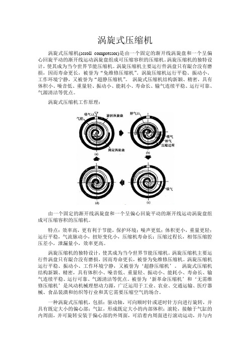
涡旋式压缩机工作原理:由一个固定的渐开线涡旋盘和一个呈偏心回旋平动的渐开线运动涡旋盘组成可压缩容积的压缩机。
特点:效率高,更有利于节能,保护环境;噪声更低;体积更小,重量更轻;运行平稳,气流脉动小,扭矩变化小,压缩机寿命长;压缩过程长,相邻压缩腔压差小,泄漏量小,效率更高。
涡旋压缩机的独特设计,使其成为当今世界节能压缩机。
涡旋压缩机主要运行件涡盘只有龊合没有磨损,因而寿命更长,被誉为免维修压缩机。
涡旋压缩机运行平稳、振动小、工作环境宁静,又被誉为‘超静压缩机’。
涡旋式压缩机结构新颖、精密,具有体积小、噪音低、重量轻、振动小、能耗小、寿命长、输气连续平稳、运行可靠、气源清洁等优点。
被誉为‘新革命压缩机’和‘无需维修压缩机’是风动机械理想动力源,广泛运用于工业、农业、交通运输、医疗器械、食品装潢和纺织等行业和其它需要压缩空气的场合。
一种涡旋式压缩机,包括:驱动轴,可向顺时针或逆时针方向进行旋转,并具有既定大小的偏心部;气缸,形成既定大小的内部体积;滚轮,接触于气缸的内周面,并可旋转安装于偏心部的外周面,可沿着内周面进行滚动运动,并与内周面一同形成用于流体的吸入及压缩操作的流体腔室;叶片,弹性安装于气缸,使其与滚轮持续进行接触;上部及下部轴承,它们分别安装在气缸的上下部,用于可旋转支撑上述驱动轴,并封闭内部体积;机油流路,是设置于轴承及驱动轴之间,并使其之间均匀流动有机油;排出端口,它们连通于流体腔室;吸入端口,它们连通于流体腔室,并相互以既定角度进行隔离;阀门组件,它根据驱动轴的旋转方向,而选择性开放各吸入端口中的一个吸入端口。
涡旋式压缩机工作原理

涡旋式压缩机工作原理
涡旋式压缩机工作原理是通过涡旋(vortex)或称为涡流(swirl)的运动原理来实现气体的压缩。
它将空气或其他气体引入一个筒形腔体,然后以高速旋转的叶轮创造一个旋转的流动场。
涡旋式压缩机的主要组成部分包括一个圆筒形腔体和一个叶轮。
腔体通常是带有入口和出口的环形结构,叶轮则位于腔体内部。
当气体通过入口进入腔体时,叶轮开始转动并产生高速涡旋流动。
在转动的过程中,叶轮的旋转力将气体从腔体底部抬升到腔体顶部,并沿着螺旋形路径流动。
由于旋转速度和叶轮设计的影响,涡旋的速度逐渐增加。
随着气体沿螺旋路径上升,它逐渐被压缩。
当气体到达腔体顶部时,它通过出口被释放出来。
同样,涡旋的运动会带动气体通过出口以较高的速度离开腔体。
通过这种方式,气体被压缩并被释放出来,实现了压缩机的工作。
涡旋式压缩机相比于传统的往复式压缩机具有一些优势。
首先,涡旋式压缩机可以实现较高的压缩比,同时具有较小的尺寸和重量,节省空间。
其次,涡旋式压缩机没有活塞和气缸等运动部件,因此运行更平稳,噪音和振动较低,维护成本更低。
然而,涡旋式压缩机也存在一些限制。
例如,由于旋转叶轮的高速旋转,会产生较高的离心力和摩擦力,导致能量损失和磨
损。
此外,涡旋式压缩机在处理高压和大气流量时可能会出现一些挑战。
总体而言,涡旋式压缩机通过利用涡旋流动的原理来实现气体的压缩,具有一些优势和限制,可广泛应用于许多领域,如制冷、空调、工业气体处理等。
涡旋压缩机英文论文(翻译)

涡旋式汽车空气压缩机的设计与制造艾克考比,JA;伊,OI 生产工程部,贝宁城市大学, 贝宁,尼日利亚摘要:这项工作的重点在于汽车用空调涡旋压缩机的设计制造。
涡旋压缩机是一种容积式压缩机,用两个互相配合的螺旋形涡盘压缩空气。
这是半封闭压缩机的设计,具有噪音小,性能可靠,效率高等优点。
@ 詹姆斯压缩机的主要功能将低压区的液体压缩和输送到高压区(罗杰斯;梅,1994)。
压缩机可分为位移式和涡轮式。
位移型进一步分为往复式和旋转式(可瑞克斯,1995)。
涡旋压缩机是一种新型的旋转式压缩机。
它的排量是靠两个相互啮合的螺旋形涡齿的压缩作用来实现的,其中一个是固定的,而另一个是有其固定轨道的,(安斯赫尔,2004)。
汽车空调系统用的典型的涡旋压缩机主要由以下几部分组成:涡齿,壳体,轴,轴承,冷冻室,橡胶密封件,平衡弹簧,电磁离合器和压力阀,如图6所示现代的涡旋压缩机技术的发展在20世纪70年代,涡旋压缩机的概念是由制冷行业提出来的。
而由他们介绍进入空调行业在上世纪80年代末,涡旋压缩机在住宅和商业应用上取得了广泛的成功。
空调压缩机主要用在小型公寓和车辆系统,如用于加热和冷却的个人家庭或企业热泵系统。
更大的压缩机是在商业领域中的应用,如冷冻机、多种冷凝机组系统。
制冷涡旋压缩机的应用范围很广,包括超市货架,散装牛奶冷却运输货车和海运集装箱等(美国制冷学会,1998;载体,2004)在这种情况下,我们提出了汽车空调涡旋压缩机的设计制造。
而据我所知,目前我们没有国产的压缩机。
致使大量的外汇用于进口它们。
因此,本研究致力于涡旋压缩机的设计和制造技术,以促进我国压缩机技术的发展从而使我们的经济得到改善。
工作原理:压缩过程的设计理念是基于两个相互啮合的涡旋盘压缩使(如图1所示)空气通过旋转轴与电机相连。
上部和下部的涡旋叶片形成新月形的压缩腔。
为降低滚动轨道,密封点在叶片两侧向内移动,推动月牙形的压缩腔向渐开线中心移动。
而随着压缩腔的移动,他们的容积逐渐减少,气体得到压缩(麦卡洛,1979;王;乔培,1994)。
毕业论文外文翻译-小型制冷压缩机研究

Small COMPRESSORCompressor refrigeration system is the core and heart of its decision to the refrigeration system capabilities and features. This paper not only energy efficient, noise and vibration and refrigeration agent analyzed small refrigeration compressor technical performance, Analysis also have appeared in recent years, the new, special small compressor main feature for us small refrigeration compressor future development trend of laying a technological foundation.As we all know, the compressor refrigeration system is the core and heart. Compressor and decided that the cooling system capacity and features. In a sense, the cooling system design and matching of the compressor is the ability demonstrated. Therefore, countries in the world are all in the refrigeration industry refrigeration compressor research invested a tremendous amount of energy, new research direction, and research results continue to emerge. Compressor technology and performance level with each passing day.1.A compressor Efficiency StudyCompressor refrigeration system is the core energy components, improve the efficiency of refrigeration systems of the most direct and effective means is to increase the efficiency of the compressor, It will bring the energy consumption decreased significantly. Moreover, can only avoid the system take measures (such as simply increasing heat exchanger area, etc.) caused by the consumption of materials increased. In recent years, as world energy shortage situation worsens day by day, more and more attention to various energy-saving work the energy efficiency of products made by the ever-increasing demands. Due to losses such as friction, leakage, harmful heat, the electrical loss, flow resistance, noise vibration of existence, Compressor work far below the actual efficiency of theoretical efficiency. Therefore, from a theoretical point of view, any reduction in a loss of arbitrary measures toimprove the efficiency of the compressor. The objective facts have led to the energy saving compressor scope, direction, width, research topics and results varied.On the current international energy-efficient compressors research concentrated mainly in a few areas : research lubrication properties Compressor parts of the friction bearings to reduce friction characteristics of power, improve the efficiency of the compressor; reduce leakage losses to improve the efficiency of the compressor; using frequency modulation technology or refrigeration system through the effort with the user load to match the best energy saving In this regard the particular frequency technology has been relatively mature well known and not repeat them here. Valve Research is an old topic but it is also an eternal topic, Improvement of the valve designed to improve the efficiency of the compressor also Nagamochi endless harvest. Research in this area many times, from the valve material, sports law, optimizing the structure of the applicable theory, exhaustive testing methods. In short, energy-saving compressors on the research in recent years has become one of the refrigeration industry first hot issues.In recent years, domestic refrigeration compressor industry to studyenergy-saving products are also giving great concern. Progress larger products mainly refrigerator compressor industry. In China efficient refrigerators GEF projects to promote and support, both the enterprises for energy-efficient products is the understanding of the performance of refrigerator compressors have a qualitative leap. At present, domestic enterprises refrigerator compressor products of the highest energy efficiency has reached 1.95%. Refrigerator compressor domestic enterprises to take a lot of technical measures such as high efficiency motors or synchronous motor, concave valves, Plane thrust bearing, low viscosity lubricants, the new Getter muffler, reducing friction losses, and achieved great results. The main problem is the lack of domestic enterprises currently free technology, the technology has to imitate the line mainly, Most of the enterprises to build their own technology infrastructure alsounconscious, nor the interest, and this restricts the development of technological capacity.Relative to the refrigerator compressor industry, domestic energy-efficientair-conditioning compressor study it was not perturbed, Over the years the efficiency of the compressor is no substantive change, greater market demand makes most of the air-conditioning compressor enterprises will concentrate on expanding production on. With the nation on the air conditioner energy efficiency standards set for the further improvement of China's air conditioner exports various perils of showing, domestic air-conditioning compressor of this short-sighted enterprises will be unable to adapt to the energy-saving development of the situation. Enterprise also on the follow-up is weak.2. Compressor noise and vibration studyCurrently, the noise has been regarded as one of the serious pollution. Household refrigeration equipment as the source of power and heart, refrigeration compressor noise, to be a measure of its performance as an important indicator. In fact, to a compressor speaking, Most of the noise is due to shell by some noise from the source excitation (such as springs, refrigerant pressure pulsation, exhaust pipe, lubricants etc. excited). But compressor noise sources and pathways complex and diverse, which gives the compressor noise silencer brought great difficulties.On the compressor noise, vibration and foreign scholars have conducted a large number of long-term research. Here in this regard to the main research results are summarized below :The main refrigeration compressor noise Exaggerative inlet, exhaust radiation aerodynamic noise, mechanical moving parts of machinery noise and noise-driven motor three components :2.1 Aerodynamic noiseCompressor inlet airflow noise is due to the intake manifold pressure pulsation in the elections. Inlet-frequency noise and the intake manifold gas Lane same frequency pulsating with the speed of the compressor. Compressor exhaust noise is due to air in the exhaust pipe caused by fluctuating pressures. Exhaust noise than the inlet noise weak, so the compressor aerodynamic noise generally Inlet mainly noise2.2 Mechanical NoiseCompressor mechanical noise, including members of the general impact and friction, the piston vibration, noise impact of the valve, These noise with randomness, was puted.2.3Electromagnetic noiseCompressor electromagnetic noise is generated by the motor. Motor noise and aerodynamic noise and mechanical noise is weaker compared. Noise source compressor inlet, exhaust, aerodynamic noise, the strongest, followed by mechanical noise and electromagnetic noise. Through in-depth studies, we can further that the main compressor noise from the vibration (from the Department of spring, Refrigeration medium pressure pulsation and smoke exhaust pipe and lubricants have incentive) to the ambient medium spread formation noise. On the effort to reduce compressor noise, much of the literature (abbreviated) proposed a series of measures and the Noise and Vibration Reduction program :① increase rigid shell structure to improve the overall resonance frequency reduces vibration amplitude;② curvature of the shell to avoid mutation, the surface, and the natural frequency is inversely proportional to the radius of curvature. shell shape it should be the smallest curvature radius;③ spring bearing flags will be moved to higher rigid position;④ shell should be used as little as possible of the plane; bending stress and the stress coupling membrane (just on the surface) will shell itself is fairly rigid. Therefore compressor shell to be used as little as possible planar structure;⑤ avoid the exhaust pipe and condenser incentive, optimizing exhaust flow pulsation, Exhaust pipe used in the introduction of additional volume to the elimination of pressure fluctuation spectrum of high-order harmonics;⑥ non-symmetric shell shape; Symmetrical three-dimensional structure means that the axis, along the main axis biggest stress of least resistance. Therefore it is asymmetrical shell structure means that the compressor can be greatly reduced along the axis direction of a force while the probability;⑦ set inlet, exhaust muffler, the closed Compressor Muffler generally muffler. It uses Cross Section, resonant cavity caused acoustic impedance changes in reflectivity or sound energy consumption. or use acoustic-acoustic send phase difference of 180 degrees to offset the muffler of noise. Shell compressor in the lateral closed Unicom a Helmholtz resonator, namely : Helmholtz resonator from the chamber through the neck hole and shell compressor connected into the internal cavity, to reduce compressor cavity stimulated acoustic modal amplitude. The results showed : resonator resonance frequency modulation of the actual compressor cavity stimulated the greatest vibration modes, will be substantially reduced resonance peak response spectrum and lead to significant change. However, it will affect the appearance andthe compressor refrigerator settings, the research results are not yet applied to products.Lubricants and residual volume-coil motor windings will lead to the same types of bulk compressor levels between different (from levels average). By changing the shell external support to increase torsional stiffness and reduce vibration surface; Noise study the complex requirements of researchers has strong theory, the enterprise has good skills base and the need for greater investment and a longer timeframe. This is domestic enterprises compressor one of the weak links, which is now basically in the qualitative phase of experimental research, Along with a great chance and randomness.3. new refrigerants ApplicationBased on the new environmental requirements of refrigerant compressor refrigeration industry is a hot issue. As for the refrigerator product R22 refrigerant substitutes the end of the work, new refrigerant compressor in the past few years mainly concentrated in the air conditioning industry. Apart from the now relatively mature R410A, R407C the study, The largest is the hot issue of CO2 compressor. This is the only issue for a briefing.CO2 currently on the research and application of concentrated mainly in three aspects : one is the most urgent need of alternative refrigerants applications, such as automotive air conditioning, as refrigerant emissions, environmental harm, must be adopted as soon as possible without endangering the environment refrigerants; the other is to consider the characteristics of CO2 cycle, the most favorable to the use of this cycle of occasions, If heat pump water heater is to supercritical CO2 in hot conditions decentralization there is a significant temperature slip will help heat Water heated to a higher temperature characteristics of the focus of public attention; another one is CO2 into account the nature of heat transfer properties and characteristics of using CO2 as a refrigerant, taking into account CO2 good cold flow properties andheat transfer characteristics, use it as a cascade refrigeration cycle cryogenic stage refrigerants.Compressor transcritical carbon dioxide as an air conditioning system efficiency and reliability of the most affected parts, It should be fully integrated supercritical carbon dioxide cycle specific characteristics of a new design. Like ammonia and CO2, the adiabatic exponent K value higher, up 1.30, it may result in the compressor discharge temperature high, However, as the needs of CO2 compressor pressure ratio small, there is no need for cooling the compressor itself. Adiabatic index is high pressure over the small, I can reduce the gap compressor further expansion of the volume losses to the higher volume efficiency compressors. After experimental and theoretical research, Jurgen Horst SUB and found Kruse, reciprocating compressor is a good film sliding seal as the preferred CO2 system. 8:3 its carbon dioxide compressor exhaust valve for improved Exhaust improved compressor efficiency of carbon dioxide increased by 7%.As the carbon dioxide pressure is far greater than the traditional critical circulatory pressure, compressor shaft seal design requirements than the original compressor is much higher, compressor shaft seal leakage over a period of time is still hampered Actually, the main reason.Danfoss, Denso, ZEXEL such as carbon dioxide compressor has entered the stage of small batch production.The IEA in March 1999, the Joint Japan, Norway, Sweden, Britain and the United States to activate the "Selected Issue on CO2 as working fluid Compression Systems in the "three-year project.Beginning in 1994, BMW, DAIMLERBENZ VOL O, Germany's Volkswagen and Danfoss. Péchiney and other European companies launched the famous "RACE"to the joint project, the Joint European well-known universities, automotive air conditioning manufacturers and other developed CO2 automotive air-conditioning system. Subregion Motor Company has production equipment CO2 carair-conditioning systems of cars, Germany KONVECTA production to the quality of CO2 in the air-conditioned Buses run from 1996 to date. DANFOSS, the Obrist Austria, the United Kingdom have developed a carbon dioxide compressor motor. Japan DENSO, ZEXEL CO2 compressor has entered the stage of mass production.With major manufacturers inputs, the type of CO2 compressor with ordinary motor compressor trend line major swing to determine the displacement swashplate, scroll and the main variable displacement.4. New principle of refrigeration compressorsIn recent years, the new structure and working principle of refrigeration compressor made a more progress, mainly linear compressor, Elliptic compressors, compressor rotor Swing, spiral vane compressor, in the past, the author has been described in the article, here will not repeat it.Linear compressor which is the domestic refrigerator compressor industry the focus of attention. In 2004 the International Compressor Engineering Conference has five linear compressor on the article. LG and researchers still Sunpower two main companies. The past two years, several domestic enterprises in the refrigerator compressor to the development of the linear compressor, However, enterprises have the technical foundation for the domestic financial strength and the limitations of scientific research institutions, believe in a short period of time can not enter the stage of industrialization.5 the classification of the refrigeration compressor5.1 reciprocating compressorReciprocating compressor is a kind of traditional refrigeration compressor, the biggest characteristic is to achieve the capacity and pressure than any of the design. Although it is widely applied, but the market share is gradually reduced.So far, the fridge (including small freezing and cold storage device) host compound compressor is ever to give priority to. Through the optimal design of valve structure, friction pair, reciprocating refrigerator compressor refrigeration coefficient of power refrigerating capacity (units) by 1.0 (w/w) of the early ninety s to today's 1.8 or so; In addition to the energy saving technology progress, and environmental protection is closely related to the refrigerant alternative technology has also made gratifying progress, refrigerator system in our country has a large number of using R600 hydrocarbons, such as small refrigeration device is also used the new working substance such as everything. To further improve the efficiency of the reciprocating compressor refrigerator, to reduce the system noise is still the development direction of it.5.2 linear compressorStill make reciprocating linear compressor, due to the linear motion of the motor can be directly drives the piston reciprocating motion, so as to avoid the complexity of the crank connecting rod mechanism and the resulting mechanical power consumption. Linear compressor assembly as the refrigerator system has appeared, the refrigeration coefficient of linear refrigerator compressor has more than 2.0 (w/w), market prospects look good. The main problem is the design of the compressor oil system and the effective control of linear motor displacement limit point and the corresponding anti-collision cylinder technology.5.3 the swash plate compressorSwash plate compressor is also a kind of variant structure of reciprocating compressor, is mainly used in automotive air conditioning system at present. After decades of development, the swash plate compressor has become a very mature model, in possession of more than 70 of the automotive air conditioning compressor market. In spite of this, because it still belongs to the series of reciprocating structure, so in thecar air conditioning system can effect comparing (refrigeration coefficient) and only around 1.5, weight and volume is big, big. Because of the mature of swashplate automobile air conditioning compressor technology, combined with technology, further improvement in the foreseeable future, will continue to maintain a certain market share, but in a certain displacement range by substituting is inevitable.5.4 rotor compressorRotor compressor in the 1970 s by the attention of domestic, it represents the structure including the rolling piston type, sliding-vane, etc. On the rolling piston type is widely used in household air conditioner at present, there are also some applications on the refrigerator. This kind of compressor don't need air suction valve, make it suitable for variable speed operation, which can improve system performance by frequency conversion control. In order to ensure high power (3 p) of the motor output power in the performance of the rolling piston compressor, the domestic research and development and the end of last century, double rotor rolling piston compressor, is now on the market. Double rotor on the rolling piston compressor structure has two advantages: (1) force of the rotating system be improved, the machine vibration and noise is reduced; (2) increase the standalone swept volume and improve the output power of the motor.Below 3 p air conditioning unit, temporarily can not replace a good model of the rolling piston compressor. So improve the efficiency of the compression process, reduce noise and motor speed control and the R410A and other related technical issues after new refrigerating agent, etc., is a research direction of the rolling piston compressor.Sliding vane compressor is a kind of rotor compressor, mainly used to provide compressed air, displacement is in commonly 0.3-3 m3 / min, the market share is low. Rotary vane compressor sliding vane compressor is a kind of transition structure, because of its better starting performance, the compression process torque change is not big, at present is mainly used for miniature cars and some smaller displacementplumbing vehicle air conditioning system. The dynamic characteristics under high speed is the main technology of this compressor research direction.5.5 screw compressorScrew compressor with small size, light weight, easy to maintenance etc., is a model of the fast development in refrigeration compressor. On the one hand, the screw type line, structural design has made considerable progress, on the other hand, the introduction of special screw rotor milling especially grinding, improve the machining precision and machining efficiency of key parts, makes the performance of screw compressor has been effectively improved, industrialization production of the necessary hardware also has the safeguard. At present, the screw compressor is given priority to with compressed air, in medium ReBengShi air conditioning has successful application in the system. Due to increasing the reliability of the screw compressor work within the scope of the medium refrigerating capacity has gradually replace of reciprocating compressor and occupied most of the centrifugal compressor market. 5.6 scroll compressorScroll compressor has been rapid development in the past ten years, the structure of the basic theory, research and development to achieve large-scale industrial production, industrial prototype constitutes the compressor technology development new luminescent spot. The development of numerical control processing technology to realize the mass production, the vortex compressor incomparable performance advantage is the precondition of its vast in the market. A few short years, has been in the field of cabinet air conditioning holds an absolute advantage. In cabinet air conditioning system, scroll compressor refrigeration coefficient has amounted to 3.4 (w/w); In the field of automotive air conditioning, the refrigeration coefficient of scroll compressor has amounted to 2.0 (w/w), and shows strong competition potential. The development of the vortex compressor is to enlarge its range of refrigerating capacity, further improve the efficiency, using alternative working medium and lower the manufacturing cost, etc.Since there is no valve, compression force and torque and small changes in the structure make it more suitable for the advantages of frequency control of motor speed operation, it also become the main direction of scroll compressor technology development. Development of scroll compressor of variable displacement mechanism is the key point of the development of the technology. At present, the use of axial sealing technology, "flexible" theory can realize cooling/heating capacity of 10% to 100% within the scope of the regulation.Due to the vortex compressor suction exhaust characteristic of almost continuous, low starting torque and liquid impact resistance, created the condition for parallel use of vortex compressor. In parallel with the vortex compressor can greatly increase the cooling capacity of the unit, can increase from the current single 25 horsepower to single unit 100 horsepower (4 sets of single parallel), and makes the cold quantity adjustment is more reasonable, give full play to the single machine with the highest efficiency. But single in parallel, one of the biggest problems is the oil return is not the average of the unit when using single machine burning phenomenon.3.1.5 centrifugal compressorAt present in large quantity of cold (greater than 1500 kw) remain within the scope of advantage, this is mainly benefited from the cold quantity range, it has incomparable system overall efficiency. The movement of the centrifugal compressor parts little and simple, and its manufacturing precision is much lower than the screw compressor, these are the characteristics of the manufacturing cost is relatively low, and reliable. Relatively speaking, the development of centrifugal compressor is slow, due to the challenges of the screw compressor and absorption chiller. Centrifuge market capacity is around 700 ~ between 1200, because under the premise that the current technology, the machine is mainly used for air conditioning of large buildings, demand is limited. In recent years because of the large infrastructure projects are built, the centrifugal refrigeration and air conditioning compressor is becoming a hot spot of attention again. Solve surge phenomenon, improve the volume adjustment and theadaptability to change with working condition, miniaturization technology is the main development direction of the centrifugal compressor technology.3.1.6 other structure formsSingle tooth of the compressor, some structures, such as cross slider compressor unique positive displacement compressor also has a certain degree of development, but has not been formed in the domestic production capacity.5. Special refrigeration compressorsAlthough domestic enterprises household refrigeration compressors long accustomed to large-scale production mode, we are accustomed to the number of effectiveness. However, the fierce price competition situation, as products become increasingly lower profit margins, When the production of millions of compressors can only make a few million dollars of profit, some on special refrigeration compressors can be regarded as a way out. Special refrigeration compressor exhaustive, it is impossible in this enumeration. But their common feature is their production scale is small, a single high-profit products faster transition, In most cases the need for the user's requirements designed. These products lead to more and more domestic enterprises to the compressor. If the number of domestic enterprises are developing or already have production capacity of the refrigerator compressor truck翻译小型制冷压缩机研究压缩机是制冷系统的核心和心脏,它决定了制冷系统的能力和特征。
涡旋压缩机英文论文
Three-dimension numerical simulation of discharge flow in a scroll air compressorSchool of energy and power engineeringAbstractScroll compressor is being recognized by industry as being high competitive with conventional compressors. Plenty of publications on this subject prove an interest of the researchers as well. Further increases in efficiency may be realized if the flow losses, particularly in the final compression and discharge region are reduced. Detailed understandings of the flow processes occurring in the discharge region are necessary to analysis and reduce the discharge flow losses, which become more serious with operation at large discharge. Due to the complexity of the processes, the only one way to get the results is solving the equations of continuity and momentum using the numerical method. During the past decade, a number of investigations have been conducted on the performance of the scroll compressor. However, relatively little information are available on the details of the fluid flow characteristics within the scroll compressor chamber. In the paper, in the light of the characteristics of a discharge process, reasonable simplification of actual physical model is made and the three-dimension quasi-steady turbulent flow numerical simulation is carried out to study the flow field in the discharge region in a scroll air compressor. Three dimensionaldistributions of velocity and pressure and typical flow patterns that exits in the discharge region are presented, which gives good understanding about the physical processes in the scroll air compressor.1.INTRODUCTIONScroll compressors are applied widely in the refrigeration, air conditioning and power field as being competitive advantages in terms of high efficiency, reduced part requirement, lower noise, and reduced vibration levels. Three exist various losses when a scroll compressor is running, such as moving resistance losses of the orbiting scroll and Oldham, friction losses and flow losses. The discharge flow is the main part of these losses (approximately 3 percent of the input power is consumed due to the flow losses), especially at large discharge . Understanding of the flow processes occurring in the discharge and the final compression region is necessary to reduce these flow losses, which become more pronounced with operation at increasing speed and large discharge. Therefore, three dimension numerical simulation of discharge flow in scroll air compressor with modified top profile is carried out. The important flow patterns that exist in the discharge and final compression region are presented. The analysis results supply the theory basis for finding the sources caused discharge losses and designing the discharge port of scroll compressor, particularly at large discharge.A scroll air compressor of discharge is studied in this paper. The topprofile is modified with symmetrical arcs and the discharge port is kidney-shape port. The basic parameters and modified parameters of scroll tips are shown in the table 1.Figure 1 shows the schematic region of the scroll compressor.Table 1: The basic parameters and modified parameters of scroll tipsFigure 1: Schematic of scroll compressor discharge region.2.PHYSICAL MODELAND AND NUMERICAL METHOD2.1 Physical modelThe gas is driven and compressed by “squish motion” of the orbiting scroll wrap, and this results that an unsteady compressible viscous flow occurs within the scroll compressor working chamber. Due to high rotating speed and steep velocity gradient near the wrap wall, the turbulence characteristics have to be considered. But the orbiting wall speed is small compared to the gas flow velocities, for example, the wall speed is approximately 5 percent of the average velocity of the discharge flow in a scroll air compressor at discharge studied in this paper, so it appears justified that the quasi-steady approach is made to treat the flow field with stationary wall. That is , to ignore the moving of orbiting scroll wall is justified. Therefore, three dimension steady-state turbulence calculations are performed to predict the flow field in the final compressor and discharge region. Air is injected from two sides of thecentral chamber with the instantaneous flow rate at various crank angles. The volume flow rate at various crank angles during the discharge process is shown in figure 2.The figure 3 shows a computational model at a certain crank angle after onset of discharge.Figure 2: V olume flow rate with orbiting discharge crank angleFigure 3: Three dimensional computation model2.2 Numerical methodTurbulent flow exists in the scroll configurations considered and was treated using a normal k- turbulence model. The governing equations were discretized using finite volume method. The SIMPLE algorithm was employed in order to correct the pressure filed. Near the wall, the improved wall function method was employed. The discretization scheme of convection item and diffusion item are respectively the second-order upwind scheme and the central difference scheme. Tao (2001) shows the details of discretization method. In the light of the geometrical characteristics of computational domain, the geometry scale of different parts of the whole domain differs greatly; the block structure gird method was employed to generate grids of the whole domain being separated into several parts, in which grids were generated by the body-fitted coordinate grid system. Grids are so fine that the numerical results are grid-independent. The computational domains at different crank angles are different, so the grids were generated separately. The boundaryconditions are as the followings:(a) InletThe mass flow rate on each of two inlets is the same and equal to the instantaneous volume change rate multiplied by the density.(b)The outlet is set on the location far away as 5 times of height of discharge port in order to guarantee the constant pressure. The discharge pressure is provided on outlet.(c)Non-slip boundary condition for velocity is provided on walls. Advanced wall function method is employed to tread the near wall domain.3. NUMERRICAL RESULTSIn this paper, 0 is defined as the orbiting discharge crank angle. At the discharge moment, that is the crank angle y=45(x is the discharge crank angle), yis taken as zero. Then, y is changing from 0 to 360 degree during the whole process of discharge. According to this definition, for example, at crank angle of 45 degree after the onset of discharge is described as y=45.In this paper, for the convenience of description, location of the z coordinate equal to zero is define as the inlet of discharge port and is named as the surface of the fixed scroll. Location of the z coordinateequal to h (the height of scroll wrap) is named as the top surface of the fixed scroll.The flow field and its discharge from the central chamber region at several crank angles that correspond to 45, 90,180 degree after the onset of discharge is studied. Flow velocity vectors in different axial sections and three dimensional velocity vectors are detailedly analyzed.3.1 y=45The calculated velocity fields in different axial sections are shown in figure 4 (a)-(c) at orbiting discharge crank angle of 45 degree. The flow velocity in fig.4 indicate that flow being injected in the rear of each half central chamber, being turned as it impinges on the opposing wall of orbiting scroll of fixed scroll and proceeding towards the central region of the central chamber. In the central region, flow enters from both half central chamber, passing through throat region formed by the orbiting and fixed scroll tips and proceeds driven by the inertia. Two large scale vortexes develops in the central region near the scroll tips and some small scale vortexes develops in the rear of central chamber near the outer surface of scroll tips. Compared fig 4 (a), (b) with (c), it is shown that vortex flow develops in all different axial sections and number and scale and location of vortex are different in different axial section. That is to say this basic vortex flow pattern persists in this region throughout the entire axial extent of central chamber. Three dimensional velocity vectorsshown in fig 5 indicate clearly the distribution of axial velocity component. The three dimensional flow tends to move vertically downwards as it approaches the central region of the central chamber which is directly upon the discharge port. The axial velocity component is very large at a small axial distance of 0-10mm from the discharge port (when the height of the profile is 52mm). The axial velocity by the order of magnitude is greater than the radial velocity. In contrast, within the rear region of the central chamber, the flow is essentially two dimensional.From the fig 4 and fig 5, it can be seen that the velocity vectors in the mid axial section characterize the general nature of the flow within the entire central chamber. The flow vectors indicate both the two dimensional and the three dimensional nature of the flow depending upon the location. So, only the velocity vectors in the mid plane are analyzed below.Figure 4 : Velocity fields in different axial sectionsFigure 5: Three dimensional velocity vectors3.2 y=90Similar type of flow calculations have been performed at an intermediate crank angle (2=90). It is shown in fig 6. As the discharge process continues in an actual scroll compressor, the orbiting scroll continues to move away from the fixed scroll. This action is associatedwith a progressively increased opening of the central region to the discharge port. This implies a less occluded opening of the discharge port compared with the throat region at y=45.The velocity vectors in axial sections of mid plane and discharge are different from those at y=45 and the magnitude of velocity reduced. A double vortex was predicted to form at the mid axial section and the scale of the vortexes increased to trend to become a large vortex.Figure 6 : Velocity fields in different axial sections3.3 y=180Figure 7 (a)-(b) shows the velocity vectors in the axial sections at orbiting discharge crank angel of 180 degree. From the figure, it is shown that the velocity vectors field is obviously different from those shown in fig .4 and fig.6. A large scale vortex was developed in the discharge region as the discharge port is opened fully. In addition, a less constrictive flow passage exits on the region of the scroll tips, the velocity magnitude reduces further. The velocity vector field shows the occurrence of some small scale vortexes at the rear region of the central chamber.Figure 7: Velocity field in different axial sections4. NONDIMENSIONAL PRESSURE LOSSES COEFFICIENTTo obtain quantitative data characterizing the pressure losses of the final compression and discharge region, nondimensional pressure losses coefficient was define as below:P is the average pressure in the central chamber, pa; pd is the designed discharge pressure, pa.The variation of pressure losses coefficient * with orbiting discharge crank angel for the whole discharge process under different operation conditions is shown in fig 8. the pressure losses coefficient is very large at orbiting discharge crank angel of 0-60 degree. For example, the losses coefficient at 45 degree of orbiting discharge crank angle is approximately ten times larger than the loss coefficient at 180 degree, indicating that the flow losses are largest at the onset of discharge. This result is not surprising, since this is also the point of maximum constriction of the flow area. Furthermore, the high rotating speed and discharge pressure corroborate that significant flow losses would exist. With increasing the opening discharge port, losses coefficient is decreasing rapidly. The results indicate that discharge flow losses concentrate at the onset of discharge and reduce quickly with increasing opening discharge port.In addition, these results imply that the open-close characteristic of discharge port should be stressed to consider when designing a discharge port, particularly for compressor at large discharge. The easier to open, the better the characteristic of discharge port is. Maximum area of discharge port is possibly not the best.Figure 8: Nondimensional pressure losses coefficient with orbitingdischarge crank angle5: CONCLUSIONSInternational Compressor Engineering Conference at Purdue, July 12-15, 2004Three dimension numerical simulation of the discharge flow in a scroll air compressor was conducted to provide the characteristic of flow field in the final compression and discharge region. Detailed analysis is made of the flow velocity vectors in different axial sections. The numerical results show that complex vortex flow patterns exist in the discharge region, not only in axial sections. On the basis of numerical results, the dismensionless pressure losses coefficient is defined and the pressure losses at various crank angles after onset of discharge is analyzed. It is shown that the discharge flow losses greatly large shortly after the onset of discharge. The results shows that, the easier to open, the better the characteristic of discharge port is. Maximum area of discharge port is possibly not the best.REFFRENCES1.Hirano. T., et al., 1989, Development of High Efficiency ScrollCompressor for Heat Pump Air Conditioners, Mitsubishi Heavy Industries, Ltd., Tech. Rev. V ol. 26, No. 3, p: 512-519.2.Patankar S V, Spalding D B., 1972, A calculation procedure forheat、mass and momentum transfer in three-dimensional parabolicflows, Int. J. Heat Transfer, V ol. 15, No.11, p:1787-1806.3.Wang Yunliang, X u zhong, Miao Yongmiao, 1993, Influence ofDifferent Wall Function Methods on turbulent flow fields, Fluid Engineering, V ol. 21, No. 12, : 26-29.4.Tao Wenquan, 2001, Numrical Heat Transfer (second version),Xi’an Jiaotong University Press, Xi’an, 152p.5.Tao Wenquan, 2001, Advanced Numerical Heat Transfer, SciencePublishing Company, Beijing, 41p.6.Thompson J.F., Warsi Z.U.A., Mastin C.W., 1985, Numerical GridGeneration, Foundation and Application, North-Holland New York.。
- 1、下载文档前请自行甄别文档内容的完整性,平台不提供额外的编辑、内容补充、找答案等附加服务。
- 2、"仅部分预览"的文档,不可在线预览部分如存在完整性等问题,可反馈申请退款(可完整预览的文档不适用该条件!)。
- 3、如文档侵犯您的权益,请联系客服反馈,我们会尽快为您处理(人工客服工作时间:9:00-18:30)。
涡旋式汽车空气压缩机的设计与制造艾克考比,JA;伊,OI 生产工程部,贝宁城市大学, 贝宁,尼日利亚摘要:这项工作的重点在于汽车用空调涡旋压缩机的设计制造。
涡旋压缩机是一种容积式压缩机,用两个互相配合的螺旋形涡盘压缩空气。
这是半封闭压缩机的设计,具有噪音小,性能可靠,效率高等优点。
@ 詹姆斯压缩机的主要功能将低压区的液体压缩和输送到高压区(罗杰斯;梅,1994)。
压缩机可分为位移式和涡轮式。
位移型进一步分为往复式和旋转式(可瑞克斯,1995)。
涡旋压缩机是一种新型的旋转式压缩机。
它的排量是靠两个相互啮合的螺旋形涡齿的压缩作用来实现的,其中一个是固定的,而另一个是有其固定轨道的,(安斯赫尔,2004)。
汽车空调系统用的典型的涡旋压缩机主要由以下几部分组成:涡齿,壳体,轴,轴承,冷冻室,橡胶密封件,平衡弹簧,电磁离合器和压力阀,如图6所示现代的涡旋压缩机技术的发展在20世纪70年代,涡旋压缩机的概念是由制冷行业提出来的。
而由他们介绍进入空调行业在上世纪80年代末,涡旋压缩机在住宅和商业应用上取得了广泛的成功。
空调压缩机主要用在小型公寓和车辆系统,如用于加热和冷却的个人家庭或企业热泵系统。
更大的压缩机是在商业领域中的应用,如冷冻机、多种冷凝机组系统。
制冷涡旋压缩机的应用范围很广,包括超市货架,散装牛奶冷却运输货车和海运集装箱等(美国制冷学会,1998;载体,2004)在这种情况下,我们提出了汽车空调涡旋压缩机的设计制造。
而据我所知,目前我们没有国产的压缩机。
致使大量的外汇用于进口它们。
因此,本研究致力于涡旋压缩机的设计和制造技术,以促进我国压缩机技术的发展从而使我们的经济得到改善。
工作原理:压缩过程的设计理念是基于两个相互啮合的涡旋盘压缩使(如图1所示)空气通过旋转轴与电机相连。
上部和下部的涡旋叶片形成新月形的压缩腔。
为降低滚动轨道,密封点在叶片两侧向内移动,推动月牙形的压缩腔向渐开线中心移动。
而随着压缩腔的移动,他们的容积逐渐减少,气体得到压缩(麦卡洛,1979;王;乔培,1994)。
第一轨道开始的两个涡齿的两端完全开放,开始向间隙中充入低压制冷剂气体。
转动的轨道最终闭合制冷剂气体的第一压缩腔。
作为第一个轨道的两端,第一对新月形压缩腔具有向内移动到中间位置,转动的外端开始重新开放接纳更多的低压制冷剂气体。
第二轨道推动第一压缩腔内的气体向涡旋中心移动,不断减小气体的体积和增加气体压力。
第三轨道开始的新月形压缩腔涡旋中心的外面,作为第三轨道继续压缩,叶片的内端断开触点靠近排气孔,第三轨道继续压缩机循环,排出高压制冷气体。
动涡盘的设计图纸,涡旋示于图1-7。
压缩机的参数:轴做的是沿轨道运动的旋转运动,所以必须进行压缩机制平衡配重。
以下是在轴的设计时需要考虑的参数:扭转力矩·轴的直径(D)·剪切应力(τ)·扭转角(θ),允许负载(Fmax),壳体厚Tc轴的设计:轴是设计用来动力传输的,确定一个合适的直径,在操作过程中各种负荷和工作条件下的测定,以确保令人满意的强度和刚度。
轴通常是圆形的横截面可以是空心的或实心的。
在许多标准文本中,阐述了其设计(希格利;米施克,2001厅,等。
2002 可米和格普塔,2005)。
轴做的是沿轨道运动的旋转运动,所以必须进行压缩机制平衡配重。
(投影图如图3所示)。
我们在考虑压缩机轴与叶片的设计时对高压5叶片倾斜72oº角。
图7: 涡旋压缩机的组装图 扭矩:等价于 23.38Nm 轴径: 其中:Kb :疲劳系数应用于弯曲力矩Kt :疲劳系数施加扭转力矩Mb :弯矩Mt :扭矩但轴只有扭转应力和因此KT 是统一的KT = 1 假设KB = 1.5。
从弯矩图计算我们的最大弯矩,允许轴= 37.18nm使用ASME 规范的实心轴方程式。
Mt =23.88Nm 和Mb =37.18Nm得到d= 0.01428 m ,或 d=14.28 mm从轴的ASME 标准尺寸,我们使用轴直径15mm 因此,D = 4×15 = 60 J=1.277x10⁻⁶;3.剪应力 (τ 评估值为 : 1.4×10⁵N/m 2;4. 扭转角(θ)=584Mt LGd4 评估值为:0.44°;5. 最大负荷(负荷量)刚度为:F max =3ΔeiL 3 ;其中(转动惯量)= d 464 相当于 2.00×10⁻⁹;因此F MAX的评估值为7.8 KN9.30×10-3毫米表1:轴规格特性数值电动机功率(P) 7.50 KW电机的转速(N)3000 rev/min疲劳因素弯矩(KB) 1.50疲劳因素对扭矩(KT) 1.00轮重(W)165.00 N叶片数量 5角(O) 72°张紧力侧(N1) 356.00 N松皮带张力(N2)160.00 N电机的转速(NM)3000 rev/min额定功率(P)7.5 KW单位质量(M)0.12 Kg摩擦系数(F)0.30轴径(D)15.00 mm轴重(WS)9.98 N轴的剪应力(SS) 1.4 x 10⁵ N/m2轴的扭转角(θ)0.440横向刚度(Fmax)7.80 KN轴偏转(Y)9.3x10⁻³ mm压缩机外壳设计:压缩机壳体在内部压力的影响下有破裂的发展趋势。
这就需要设计的外壳的厚度,以便能承受很高的内部压力,在操作过程中。
套管厚度按C T方程7设计。
腔之间的泄漏室:理想情况下,涡旋压缩机的两个涡盘保持完美的接触旋转,在现实中机器的情况不是这样足够的精确,而是有一个窄窄的间隙。
差距约一微米,这可能会增加磨损或加工不良,它是已知的,如果达到八微米,压缩机就不能正常工作了。
这就是为什么我们要分析流经该间隙,以确定是否泄漏在压缩机相邻的腔室中。
几何原理图参见图8(豪厄尔,2001)。
标准的厚度D和长度L分隔两个压力为P1和P2的相邻腔室。
其中的长度尺度L似乎有点不确定。
采用沿间隙的X和Y方向穿过一个局部坐标系统的方法。
相对于这些坐标表示的底部和顶部涡旋壁(这两者都是随着压缩机旋转)的可压缩流动控制方程---斯托克斯方程其中ρ,U和P代表密度,速度和压力,λ和µ的膨胀系数和剪切粘度和d / dt的比值就是对流导数。
方程(1)代表了质量守恒定律,并且必须以任何速度U和密度ρ的满足,而方程(9)是通常可压缩流体--斯托克斯方程的推广,这是如果你设置为零恢复的点。
在压力∆变化之间的差距,我们可以推导出一个典型的粘性阻力气体流速平衡压力梯度的方程(2)(奥克登,1995)我们可以立即从速度规模中推断出泄漏了一个典型速率U,气体速率的泄露是UD率,所以在一个周期的累计损失通常是UD / W(段伦,等。
1994)我们也比较这一腔原区得到气体的相对损失和泄漏。
表2:泄漏室之间的参数估计财产约值粘度(µ)10-5 kg / m间隙厚度(D)10-6 m接触长度(L)10-2 m旋转频率(W)47.33 s-1压力变化(∆P) 1.60×10⁶ Pa涡旋压缩机腔之间的泄漏估计参数值显示在上面的表2中,相对损失约0.3%,很小,然而,它是明确的,用来增加D.高度敏感的制造工艺:涡旋压缩机的主要部件是曲轴,壳体,轴和压缩室。
涡旋压缩机的其他部分都有橡胶密封件,平衡弹簧;轴承,离合器压力阀等物品。
所以我们有我们的三个主要部分构成:曲轴,外壳和轴,压缩室由于形状复杂。
(剖视图如图2所示)曲轴:加工这些曲轴的钢坯加工成独立的渐开线曲线的形式和约束一个边缘的坚实平台。
曲轴有一个固定件,而其他旋转轨道绕转子中心运动。
这两个元素(在图所示相同的螺旋。
1和9),安装有1800相位差,有防自转机构,在这种情况下,十字滑块联轴器用于确保这些相同的螺旋组装1800相位差。
奥尔德姆联轴器在一个固定角位置上,防止自转同时允许在一个轨道的径向方向上卷轴运动。
轨道运动的幅度依赖于基圆半径和壁厚。
壳体制造方法:用厚度4mm的钢板制造压缩机壳体。
从经济角度我们选择制作加工的车床和焊接的部分。
涡旋压缩机壳体为圆筒形容器垂直分为低压和高压端。
壳体的最大容量是制冷剂吸入压力时。
一个小高压区置于压缩机的静涡盘用来降低气流脉动的声音和振动。
冷制冷剂通过下连接吸入气体进入大吸壳/套管。
气体速度在润滑剂和少量的液体制冷剂作用下从气体中分离时大幅下降。
在涡旋压缩机的吸气时,向上穿过到达曲轴的转子。
油带到压缩机的制冷剂气体夹带的雾量小,提供了必要的涡旋叶片的润滑密封。
压缩气体通过单向阀进入高压腔然后离开压缩机壳体通过排气孔排出。
壳体的下部为油储器。
压缩机高容量储槽能够在长时间运行和大量的制冷剂作用下系统操作。
测试压缩机:装配好的涡旋压缩机,接下来是测试机器能否正常工作。
在以下的观察和试验下完成:。
吸入空气在压力作用进入压缩机。
在出口处的空气量与入口处成正比。
压缩机的主要目的(即增加压力,制冷剂气体温度)实现。
几个测试项目和结果如下表。
初始压力= 1.01×10⁵ N/m2(大气压力)的初始温度为27℃表3:试验结果系列号输出压力(N/m2) 输出温度(°C)效率%实验1 1.42 x 10⁵ 57.60 63.73实验2 1.37 x 10⁵ 54.20 56.67实验3 1.65 x 10⁵ 71.80 93.33实验4 1.62 x 10⁵ 70.20 90.00实验5 1.59 x 10⁵ 68.10 85.63然后,相应的平均效率为77.88%讨论:设计概念是基于两个互相配合的涡旋盘通过曲轴与皮带轮的帮助,从电动机通过皮带驱动压缩机。
机器的尺寸是根据严格的计算的。
今天,世界上使用汽车空调涡旋压缩机的都是小尺寸。
制冷气体的压力进入压缩机决定压缩机出口的压力大小。
结论:我们在这项工作中,提出了涡旋压缩机的设计制造。
本机(压缩机)有助于压缩进入车辆空调系统的冷凝器的空气,然后到接收器,膨胀阀,蒸发器。
压缩机运行效率为77.88%。
参考文献:美国制冷协会。
1998。
标准550 / 590,水冷却设备采用蒸汽压缩循环。
空气–空调制冷协会,阿灵顿,弗吉尼亚州美国采暖制冷与空调工程师学会;(2006)。
手册,采暖,通风和空气调节系统/envi/hvac.html–布朗,R N(2001)。
压缩机的选择和调整大小。
第二版,海湾出版公司,休斯敦,德克萨斯。
载体(2004)。
高效压缩商业和工业应用公司。
锡拉丘兹,纽约,/idc/groups/piblic/doc uments.pdf超培,N P(1994)。
化学工程手册。
第二版,麦格劳山,纽约。
克瑞可斯,L.(1905)旋转发动机美国80 1182。
豪尔,A,S;豪勒文克,R;和劳克林,H G(2002)轮廓系列机械设计理论和问题,公制版。