转叶式安装舵机
武汉船机首个转叶式舵机研制成功

该 公 司首 台转 叶 式 舵机 研 制 成功 ,进 一 司 服 务部 门加 大 现 场 服 务 力 度 , 一 旦 出
步拓 展 了船 舶 配套 产业 范 围 。 现 问 题 , 立 即组 织 进 行 分 析 , 快速 提 出
武 汉 船 机 首 个 转 叶 式 舵 机 研 制成 功
日前 , 武 汉 船 用机 械 有 限 责 任公 司 力 ,优 化 工 序 ,发 挥最 大 效 率 。在 文 件 首 次承 接 并 制造 的 4 0 N M转 叶 式 舵机 资 料 方 面 ,编 制 了 详细 的工 艺 卡 片 、 装 5K ・ 顺 利通 过 法 国船级 社 ( V 检验 ,技 术 性 配 要 领 指 导 书 和各 项 试 验 大 纲 ,确 保 了 B )
该 转 叶式 舵机 为3 8 0E散 货 船 配 解 决 方 案 。经 过 一 年 时 间 攻 关 ,产 品研 4 0 U
套 产 品 ,是 武 汉 船 机 重 要 新 产 品 研 发 制成 功 。
项 目,于 2 0 年 5 开 工 。在 研 制 过 程 09 月 中 ,该 公 司 技 术 中心 与 生 产 制 造 部 门 通
一
括 具有 多种 选 择 的J t se操纵 杆 控制 eMa tr
器 的 系列 喷水 推 进 控 制 系 统 。 以前 这 种
超 动 力公 司对 U 5 5 高 效 喷 水 推 J 2型 进 器进 行 了 多项 改 进 , 重 新设 计 了转 向
样 ,U 5 5 J 2 型高 效 喷 水 推 进 器 采 用船 系 统 只提 供 给 包 括 将 柴 油 机 、 节流 阀和
一起船舶搁浅引发转叶式舵机的故障修理
收稿 日期 : 2 0 1 3— 0 5—1 1
作者简介 : 黄跃 明 ( 1 9 6 5 一 ) , 男, 福 建省 厦 门 人 , 工程 师 , 现从 事船舶机务管理工作 。
有保障。公司向 C C S申请 回国进厂维修, C C S 要求 制定了船舶空放 回国的安全保障措施。 ( 下转第 1 4页)
“ H B S 2 ” 轮除右舵无法达到满舵外 , 其余操纵性能皆
无 明显 变化 。船 体通 过 临时修 理船 舶稳 性 和抗 沉性
散装船“ H B S 2 ” 轮, 2 0 1 1 年 3月 l 1日由厦 门船 舶重工有限公司建造 出厂 , 载重 吨 5 7 0 0 0 t 。舵机为 南 京 中船 绿洲 公 司 生 产 的 H D 8 0—3型 的转 叶式 舵
内部绝对清洁 , ( 不能有任何杂质 和空气 ) , 一般不 会有 比较大的故障, 运行工况相对稳定 。
l 故 障的产 生
度水下检验公司进行检验 , 在水下检验确定漏水处 , 安排水下焊补。针对转叶式舵机转子相对舵杆实际
向右产生滑移的故障 , 船员 和印度航 修队多次尝试 检修恢复 , 但 因条件限制 , 难度很大而未果。船舶搁 浅需进一步进坞检查修复 , 由于当时印度 V I Z A G港 周边的船厂均没有空坞 , 等待 时间要几个月。考虑
0 前言
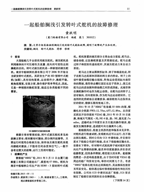
大型船舶几乎全部采用液压舵机。液压舵机是 利用液体的不可压缩性及流量 、 流向的可控性达到 操舵 的 目的 。转 叶式 液 压舵 机是 一 种新 型 的液压 舵 机。南京 中船绿洲机器有 限公 司于 2 0 0 6年开始 自 主研发转叶式舵机。其研发生产 的 H D型转叶式舵 机( 如图) , 具有结构 紧凑 , 运动部 件少 , 操舵平稳 , 舵角范围宽 , 安装方便 , 操作维护简单等优点 , 因此,
转叶式舵机
往复柱塞式舵机以上舵承来承重舵系,下舵承来定位,操控 简单,维修方便,但占用空间大,旋转角度小,一般不超过 45° 转叶式舵机占用空间小,操控高效,舵机承载全部舵重, 全部舵重承载在推力轴承上,舵角旋转角度大,可达70°,但 价格昂贵,维修成本高。 (RV2600-3 旋转范围可达75°)
转叶式舵机
注:液压螺母拆除前测量螺母与
舵杆上平面间的高度:记“B”
4、端盖摆放时应在下端面上摆放柔和的垫枕,防止端面及轴承受伤,清理 缸体中的液压油
使用船方气泵抽油
5、将油泵油管接到液压螺母和转子上,泵1接液压螺母;泵2接转子连通转 子锥面油槽 6、泵压前测量转子上端面到舵杆上端面的高度A
7、给1号泵打压,给转子泵松时预留 缓冲压力。压力查找说明书
探索
一、舵机基本简介
二、转叶式舵机构造及工作原理
三、转叶式舵机的拆装工艺及注意点
一、舵机基本简介及构造
船用舵机目前多用电液式,即液压设 备由电动设备进行遥控操作。
有两种类型: 一种是往复柱塞式舵机, 其原理是通过高低压油的转换而做功产生直 线运动,并通过舵柄转换成旋转运动。
另一种是转叶式舵机,其原理是高低压 油直接作用于转子做旋转运动,体积小而高 效,成本较高。
推力轴承
三、转叶式舵机的拆装工艺及注意点
1、将转子、舵杆用液压油清洁干净(主要两者的配合锥面) 2、安装底部油封和铜套(新铜套数据核验) 3、回装转子,落下时确保转子水平安入,让转子全部重量 承载到舵杆锥面上(转子两侧密封:弹簧型?不锈钢条型? 安装时注意点)
附:回装油腔密封条时,若单 侧间隙过小怎么回装?什么原 因引起间隙不均?
8、保持1号泵不动,给2号泵打压直至 1号泵压力跟着上升,此时意味着转子 已松动。同时可以听到一声响声 9、然后1号泵缓缓泄压,转子缓缓上 升,与舵杆脱离。
辅机安装舵系安装

⒊舵线确定后的检查项目
⑴对于单桨单舵的船舶,两线的距离允许偏差δ≯0.01 L⅓ mm(式中L为船长,单位为米)。对于多舵船舶的各舵系中心 前后位置及相互位置偏差均应不大于5 mm。
⑵舵线与轴线的垂直度偏差应不大于1mm/m。 ⑶另外,还应检查图一53—44中所示的各部位尺寸,包括舵
系中心线与尾管毂后端面的距离,以及到各轴承的距离尺寸。 以供确定舵轴的长度尺寸和计算螺旋桨与舵叶之间的安装间 隙是否满足设计要求。
㈣舵杆与舵叶的安装
舵叶的轴向位置是借助于上轴承下部的调整垫来得到保证。 在舵杆上拧入起吊螺栓,从上、中舵承孔内放下钢丝绳与起
吊螺栓连接后,扶正舵杆,即可将舵杆吊进中、上舵承。要 求将上舵杆尽量往上吊,使其下面让出尽可能高的空间位置 供吊装舵叶用。舵叶销轴能插入下舵承的铜套内,舵叶装到 位,转正舵杆,放下传动键,落下舵杆,使两法兰端面靠住, 打入紧配螺栓与固定螺栓并将其固紧。然后将舵杆连同舵叶 一起吊起一定距离,在下舵承端面垫以一定厚度的垫片。解 除上舵杆上的钢丝绳,将上舵承体、滚动轴承、垫板等整体 套入上舵杆,将舵承体及轴承都安装到泣,然后装两半承压 环、套环等。再装上钢丝绳,将整个舵吊起,取出下舵承的 垫片后,把舵放下,拆除钢丝绳,装上压盖。检查舵叶与下 舵承铜套端面之间隙,应在设计规定的范围之内。 安装完毕,用手推动舵叶,检查其转动是否灵活。对于舵杆 直径小于360mm的舵叶,在2~5人推动下能灵活转动,即 表示安装良好。然后,装中舵承的密封橡胶圈并用压盖压紧。 装上舵柄后,即可。
用平尺和角尺侧量上端面与舵线的垂直度,用内卡测 量其内孔壁与舵线的距离,使其中心线与舵线重合。
测量舵机房甲板至假舵下端面的距离,即可按照图纸 要求,将上舵承座割至应有的高度。再用上述方法将 上舵承座的中心线与舵线重合。然后焊接上舵承座, 将上舵承本体安装在上舵承座上,并装上推力轴承。
舵机转舵机构和遥控系统讲解

十字头式转舵机构的特点:
1)扭矩特性良好,承载能力较大,能可靠地平衡撞杆 所受的侧推力,可用于转舵扭矩很大的场合。
2)撞杆和油缸间的密封大都采用V型密封圈。密封圈工 作油压越高撑开越大,从而更加贴紧密封面,故密封可靠, 磨损后还具有自动补偿能力。此外,密封泄漏时较易发现, 更换也较方便。
3)油缸内壁除靠近密封端的一小段外,都不与拉杆接 触,故可不经加工或仅作粗略加工。
力矩马达式:舵机遥控系统的控制电路采用了无触点控制, 并取消了浮动杆追随结构。(见下图)
二、伺服油缸式舵机遥控系统 (属电液式)
伺服油缸式舵机遥控系统:(动画)
泵控型舵机液压系统
单动(非随动)操舵系统:只能控制舵机的起停和转舵方 向,当舵转至所需要的舵角时,操舵者必须再次发出停止转 舵的信号,才能使舵停转。通常既可设在驾驶台,也可在舵 机室操纵,以备应急操舵或检修、调试舵机之用。
随动舵、自动舵和非随动(单动)舵控制框图如下所示:
一、伺服电机式舵机遥控系统
1.直流伺服电机式舵机遥控系统( 属电气式,见动画 ) 2.交流伺服电机式舵机遥控系统(力矩马达式,属电液式)
4)油缸为单作用,必须成对工作,故尺寸、重量较大。 而且撞杯中心线通常都按垂直于船舶尾线方向布置,故舵 机室也需要较大的宽度。
二、 拨叉式转舵机构(动画)
受力分析:与十字头式转舵机构相同。
拨叉式转舵机构特点:侧推力可直接由撞杆本身承受而无需导
板。撞杆轴线至舵杆轴间的距离R0可缩减26%,撞杆的最大行程
图示为AEG型转叶式油缸 及密封装置。
回转式转舵机构特点: 1)占地面积小,重量轻,
安装方便; 2)无需外部润滑,管理
简便,且转舵时舵杆不受侧 推力,可减轻舵承磨损;
转叶式液压舵机安装作业指导书

转叶式液压舵机安装作业指导书
一)准备工作:
1)准备图纸,安装工艺。
2)液压工具两套,用于径向及轴向施压,并配齐连接接头及垫片。
3)百分表及表座一套,用于测量推进量。
4)按规定要求的液压油,用于补充油泵。
5)棉纱,细锉刀,油石,细砂布,二硫化钼,及常用工具。
二)安装前要求:
1)舵叶与舵杆完工,并交验合格。
2)舵叶已处于“O”位状态,舵杆与船体的密封装置装妥。
3)舵杆与船体的“O”位记号已经做妥。
三)安装过程:
1)舵杆与舵机的配合锥面仔细清洁,如有毛头毛刺,在服务工程师的指导下去除掉,并最终用油石磨光。
2)将舵杆舵机的配合锥面涂上液压油。
3)舵机缓缓落下,要特别防止舵机与舵杆螺牙的碰撞,落位后再复查舵机与舵机座位置,确认无误。
4)舵杆螺牙与液压螺母牙涂上二硫化钼,旋到位。
5)接好液压油泵,架妥百分表,按工艺要求的推进量,压合配合锥面,并按规定时间保压。
6)调整舵机止跳块的间隙至工艺规定值,调整舵杆(舵销)间隙至规定要求,并将舵机的顶生螺栓旋紧。
7)按舵机底脚孔小1---3MM左右钻孔,并配妥固定垫块,用贯穿螺栓紧固,一般选钻对角四只螺孔即可。
8)复查舵叶止跳块间隙,应仍符合工艺图纸要求。
HD 80-3转叶式舵机使用说明书
闪点(开口)1600C
凝点-350C
四、舵机的使用
舵机的使用人员必须十分清楚,舵机是船舶的重要生命线,它的及时正确工作与否,直接影响船舶的生命和安全。因此,使用人员必须熟悉舵机的使用说明书,了解舵机各部分的作用、结构、原理,以及正确使用管理的方法,加强维护保养,现分述如下:
1.舵机运行前的准备
3)储备油箱——它为本操舵装置液压系统上的一个附件,为液压系统供油和补油所需;
3.本操舵装置的配置和控制形式
本操舵的额定转矩为750kNm,通过操纵手柄的控制,根据舵工作需要,两泵组互为备用,不应同时使用。在应急情况下,泵组除了电气控制,还可以通过设在电磁两端的按纽进行手控。
4.舵机的技术性能
舵机型号
3.舵马达基本结构及原理
舵马达主要由圆筒形缸体、转子和端盖组成,转子在舵马达底部和顶部的两支承内转动。转子上的动叶接受油箱后输出扭矩,转角运动受到缸内扇形体的限制,扇形体由螺钉固定在定子壳体上,使之在舵马达的进油侧和排油侧之间形成挡板。此扇形体在舵作满舵操作时也作为舵止动器。
在舵马达的转子上设有轴向、径向密封条,作为舵马达运动密封件。它选用的优质耐油合成橡胶条,确保舵机马达保持良好的密封,能够长期有效地工作。
HD80-3
舵
机
装
置
舵杆直径(mm)
Ф390
转舵角度
±35°
最大舵角范围
±36.5°
额定工作压力(MPa)
7.5
转舵速度
单舵≤28s (650)
安全阀设定压力(MPa)
9.375
额定扭矩(kNm)
750
舵机重量(kg)
6000
舵机尺寸
Ф1500×1105
液压舵机的转舵机构.
在实际中,随着α的增大,该机构P比滑式增加快
8-3-1-2 滚轮式转舵机构的特点
(1)撞杆与舵柄之间没有约束,无侧推力
结构简单,加工容易,安装、拆修都较方便
(2)每个油缸均与其撞杆自成一组
可根据实际需要,分别采用单列式、双列式或上下重迭式等 不同的布置形式,提高了布置上的灵活性
4
M
zQRm
4
D 2 zpo cosR0m
式中:R。——滚轮中心到舵杆轴线的距离
上式表明
在D、R。和Pmax既定时,滚轮式转舵机构所能产生的转舵扭 矩将随α。的增大而减小
扭矩特性在坐标图上是一条向下弯的曲线
在最大舵角时,水动力矩较大,而滚轮式这时所产生的扭矩 反而最小,只达到滑式机构的55%左右
密封不如往复式容易解决 容积效率低,油压较高时更为突出
(5)内部密封问题是其薄弱环节
工作油压不超过4MPa左右,限制了它在大功率舵 机中的应用
随着密封材料和密封形式的不断改进,Pmax已可 达10~15MPa,转舵扭矩也提高到3000 kN·m 左 右
AEG型转叶式油缸
8-3-2 AEG型转叶油缸特点
当公称转舵扭矩既定时,滑式转舵机构尺寸或 最大工作油压较其它转舵机构要小
实际工作油压随实际需要的转舵扭矩而变
由式可知,舵机在实际工作中撞杆两端的油压差
P
4Mcon2 D2 zRm
可见,随着舵角α增大,尽管转舵扭矩也在增大, 但COS2α却相应减小,所以滑式转舵机构的工作油 压也不会因α的增大而急剧增加
翻边端盖与空心的轮毂3制成一体,然后用V形密封圈9 和压盖8防止油外漏
这种结构的端盖能够承受较高的油压而不易变形,同时 又可避免转叶和端盖间的泄漏。而用球墨铸铁制造的转 叶4和定叶5,则用由高强度钢制成的定位销和内六角螺 钉分别固定在铸钢的转子3和缸体2上,并用在背后装有 O形橡胶条的钢制密封条7来保证各工作腔室间的密封
- 1、下载文档前请自行甄别文档内容的完整性,平台不提供额外的编辑、内容补充、找答案等附加服务。
- 2、"仅部分预览"的文档,不可在线预览部分如存在完整性等问题,可反馈申请退款(可完整预览的文档不适用该条件!)。
- 3、如文档侵犯您的权益,请联系客服反馈,我们会尽快为您处理(人工客服工作时间:9:00-18:30)。
Porsgrunn Steering Gear ASSHIPYARD’S MANUALFORPORSGRUNN ROTARY VANE STEERING GEARSERIAL NO. :TYPE : SHIPYARD : HULL NO. :YEAR :Dokkveien 10, N-3920 Porsgrunn, Norway. Telephone: +47 35 93 12 00 Fax: +47 35 93 12 01INDEX INDEX (2)1 INTRODUCTION (3)1.1 Storage of the Steering Gear and Steering Gear Parts (3)1.2 Lifting of the Steering Gear and the Hydraulic Power Units (HPU’s) (4)1.3 Earthing of the Rudder Stock (5)2 REFERENCE DRAWING (6)3 PRELIMINARIES (7)3.1 Fitting of the Friction Connection (7)3.2 Preparation of the Steering Gear Foundation (8)3.2.1 Casting (8)3.2.2 Steel chocks (8)4 INSTALLATION (9)4.1 Installation and Alignment of the Actuator (9)4.1.1 Adjustment and entering of the actuator to the rudder stock (9)4.1.2 Pull up using the oil injection method (9)4.1.3 Mounting the actuator to the foundation/deck (12)4.2 Installation of the Lower Packing Gland and the Packings (13)4.3 Installation of the Hydraulic Power Units (HPU’s) (14)4.4 Pipe Installation (16)4.4.1 When the HPU’s are mounted directly on the steering gear unit (16)4.4.2 When the HPU’s are mounted on deck (16)4.5 Installation of the Mechanical Rudder Angle Indicator (17)4.6 Installation of the Feedback Units and the Rudder Angle Transmitters (18)4.7 Electrical Part (19)4.7.1 General (19)4.7.2 Electrical Installation (19)5 START UP (20)5.1 Oil filling (20)5.2 Pre-Commissioning (20)5.3 Commissioning (21)1 INTRODUCTIONThis manual shall give the installation contractors of the Porsgrunn Rotary Vane Steering Gear all information they need to perform a correct installation of the product.The Installation Manual consists of two parts:• The first part consists of a general description of the installation procedure for the steering gear and is not to be subject for changes related to each particular project.•The second part consists of technical specification and drawings to each specific steering gear.Before installation, please read carefully these two parts and pay special attention to the following remarks:1.1 Storage of the Steering Gear and Steering Gear Partsainted parts have to be checked against corrosion every two months. Any corrosion ll non-painted surfaces are protected against corrosion by means of rust preventive.ny damages caused by improper storage will not be covered by theAll equipment shall be stored in a dry building, well protected against weather, moisture and temperature fluctuations. This is important in order to avoid condensation.Pfound must be removed immediately, and the surface must be protected against further corrosion by means of new paint or rust preventive.A These surfaces have to be checked against corrosion every month. Any corrosion found must be removed immediately. Renew rust preventive if necessary.A guarantee.1.2 Lifting of the Steering Gear and the Hydraulic Power Units (HPU’s)The following figures show Porsgrunn Steering Gear’s (PSG’s) recommendation of lifting the steering gear and the HPU’s.Any damages caused by improper lifting will not be covered by theguarantee.1.3 Earthing of the Rudder StockTo avoid corrosion on the actuator bearings, the rudder stock should be earthed. This can be done by an earth conductor connected with a 16mm bolt to the top of the rudder indicator shaft. Remember that the conductor must be flexible to allow the turning of the shaft.2 REFERENCE DRAWINGPlease study the reference drawing, figure 2.1, before starting the installation procedure.Figure 2.1Porsgrunn Rotary Vane Steering Gear3 PRELIMINARIESExtreme care should be taken to avoid foreign particles entering the actuatorduring all steps of the installation. Pay special attention to the clearancebetween the rotor and bearings. Neglecting this will cause serious damage tothe steering gear and may lead to total break down.Welding on the steering gear actuator is strictly prohibited. Neglecting tofollow this warning may cause severe damage to the actuator structure andthe bearings.3.1 Fitting of the Friction ConnectionIf the fitting has already been done, proceed to section 3.2.If not, follow the procedure below. The result of the fitting shall be inspected and approved by the class society.1.Degrease the conical part of the rudder stock and the rotor, and check thatthere are no burrs, dents etc. on the surfaces.2.There is a "0" position mark (midships) on the rotor. Make sure that there is acorresponding mark on the rudder stock.3.Coat the conical part of the rudder stock with a colour indicator (Paris blue orsimilar). Connect the rotor and the rudder stock according to the marks in step2.4.Disconnect the rudder stock and the rotor. The contact area must comply withthe class requirement. Make sure that there is contact in the upper and lowerpart of the connection, avoiding oil leakage during pull up.5.If the contact area does not comply with the class requirement, grinding willbe necessary.The grinding tool should preferably be a high speed rotating grindingmachine with emery cloth lamellae - outside diameter size approx. 50 mm,or cylindrical emery cloth grinding wheel.6.After grinding, repeat step 3 – 5 until the contact area complies with the classrequirement.3.2 Preparation of the Steering Gear FoundationThe foundation must be dimensioned and mounted on the deck according to the class requirement. Class approval of foundation and chocking is the shipyard’s responsibility.3.2.1 CastingIf the actuator is mounted by means of casting, the contact surface between the foundation and the actuator flange must be cleaned and prepared according to the recommendations from the supplier of the cast.3.2.2 Steel chocksIf steel chocks are used, the top surface of the foundation has to be machined with an inclination outward from the centre of about 0.3°. Recommended thickness of the steel chocks is 20-30 mm.4 INSTALLATIONWhen the foundation and the friction connection between the rotor and the rudder stock are approved by the class society, the steering gear installation can begin.4.1 Installation and Alignment of the ActuatorThis description assumes that the rudder stock and the rudder have been lifted into place, marked and mounted in the correct position. Be aware of jumping allowance and make sure that the rudder stock and the pintles, if any, are aligned in all bearings.4.1.1 Adjustment and entering of the actuator to the rudder stockMake sure that the lower packing gland is mounted on the actuator beforestarting the installation.1.Lower the actuator onto the upper cone of the rudderstock. Set the “0” positionmark on the rotor and the “0” position mark on the rudder stock in line.2.Let the actuator rest with its weight on the rudder stock. At this point, thedistance from the foundation to the steering gear flange equals the thickness of the chocking + the pull up length (see the technical specification).3.Mount the hydraulic ring piston and the rudder stock nut. Make sure that therudder stock nut is tightened up completely.4.1.2 Pull up using the oil injection methodThe pull up length is to be found in the technical specification. Pumps and fittings used must be capable of minimum 1000 bar.1.Pump oil into the ring piston using pump A, see figure 4.1, until oil appears inthe ventilation hole. Plug the hole.2.Pump until a pressure of 50 bar is obtained in the ring piston. From this point(0-point), the pull up length is to be measured.It is important to measure the distance from the top of the rotor to the top ofthe rudder stock. Do not measure from the rudder stock nut!stock is pulled into the rotor. If this is the case, keep on using pump A until final pull up length is reached.Continue until the rudder stock is pulled up to the required pull up length. It is normal to pull up 0.1-0.2 mm longer than the theoretical pull up length, due to fall back when the pressure in the piston is released.8.After pull up, there should be a diametrical clearance of approximately 0.15 –0.25 mm between the upper bearing and the upper rotor neck.9.When the pull up length is reached, the pressure in pump B can slowly bereleased and the pump can be removed.10.After approx. two hours, release the pressure in the hydraulic ring piston, andremove pump A and the plug.11.Fully compress the ring piston by turning the rudder stock nut.12.Harden up the rudder stock nut.13.When the tightening of the rudder stock nut is done, allow the actuator to restfreely on the rudder stock cone. The distance from the foundation to thesteering gear flange equals the thickness of the chocking.14.Place the tab washer on the nut. Mark the nut according to the holes in the tabwasher. Drill and tap the holes.Make sure no chips from the drilling and tapping contaminates the steering gear!15.Fasten and secure the tab washer, see figure 4.1.2.Figure 4.1.2 Tab washer securing sketch16.Allow the actuator to rest freely on the rudderstock. Fasten the adjustmentscrews, 4 pieces, in the steering gear flange, and continuously check theclearance between the rotor and the bearing. When all four adjustment screws are fastened, there must be clearance in four directions in the bearing. If there is no clearance in one of the directions, adjust the screws until there isclearance in all four directions.4.1.3 Mounting the actuator to the foundation/deck.When the actuator and the rudder stock are fixed in the middle position with the four adjustment screws, and all clearances are accepted, it can be drilled and broached for the foundation bolts. All the foundation bolts should have a tolerance of H7/m6 and be adjusted individually. For mounting of the actuator to the foundation/deck, casting or steel chocks can be used.Casting1.Mount the foundation bolts without pretensioning.2.Check the clearance between the upper bearing and the rotor neck once again.Make sure that there is clearance in four directions before casting.3.Perform the casting according to the supplier’s recommendations and classrequirements.4.When the cast has hardened and is accepted by the supplier, tighten thefoundation bolts.Steel chocks1.Measure up and prepare four steel chocks.2.Mount and fix the steel chocks with their four respective foundation bolts. Theclearance in the upper bearing should be checked before fixing the remainingfoundation bolts.3.After tightening, there should be no clearances exceeding 0.05 mm betweenthe steel chocks and its contact surfaces.Perform a final check on all clearances.Length = π • d + 10 mm,where d is the rudderstock diameter.2.Loosen and unscrew all counter nuts.3.Unscrew the nuts and lower the packing gland.Examine for pits and scoring before installation of packings. Clean the sealing surfaces thoroughly.4.Tighten all stud bolts.5.Measure height H1 and H3, see figure 4.2.2, then calculate H4 from thefollowing formulas:H2 = H1 - (5 x thickness of packing)7.Repeat step 6 for installation of all the packings.8.Lift the gland in place and screw one nut on each stud bolt.9.Tighten the nuts in a cross pattern until H4 is as calculated in step 5.It is very important that H4 is equal all around to get even press on thepackings.10.Further tighten all nuts ½ turn in a cross pattern.Do not over-tighten the nuts. This will result in damage to the packings andconsequently leakage.11.Screw on and hand-tighten the counter nuts. The final tightening and securingof the counter nuts shall be done during commissioning.4.3 Installation of the Hydraulic Power Units (HPU’s) Depending on the type of the steering gear, the HPU’s can either be mounted directly on the steering gear unit or be fastened to the deck.For both cases it is very important that the alignment of the pump/motorcoupling is correct, see figure 4.3.1 and table 4.1 and 4.2. PSG takes noresponsibility if the pumps are started without the correct alignment.Table 4.1 Deviation values for flexible coupling alignmentCOUPLING TYPE MaxKr (mm)MaxKw (°)MinS (mm)MaxS (mm)A 24/32 SINT 0,10 0,7 2,0 2,7 A 28/38 SINT 0,12 0,7 2,5 3,25 A 38/45 GG 0,12 0,7 3,0 3,9 A 42/55 GG 0,15 0,7 3,0 4,0 A 48/60 GG 0,17 0,8 3,5 4,55 A 55/70 GG 0,18 0,9 4,0 5,1 A 65/75 GG 0,20 0,9 4,5 5,8 A 75/90 GG 0,20 0,9 5,0 6,5 Table 4.2 Proportional displacement tableAD RD0 % 100 % 10 % 90 % 20 % 80 % 30 % 70 % 40 % 60 % 50 % 50 % 60 % 40 % 70 % 30 % 80 % 20 % 90 % 10 % 100 % 0 % In case of angular displacement (AD) and radial displacements (RD) at the same time, you can use the values only proportionally. Example:AD 90% => RD max. 10%4.4 Pipe InstallationIn order to obtain steering gear performance according to the specifications, it is important to ensure that the pipes are installed properly. For each steering gear PSG have made a proposition in the general arrangement drawing, which is to be found in the second part of the manual.4.4.1 When the HPU’s are mounted directly on the steering gear unit Normally the pipes are adjusted, mounted and tested by PSG. If the pipes are dismounted, the flanges are marked by PSG for correct reconnecting.In cases where the yard is disconnecting the pipes, they are responsible for marking the flanges properly.4.4.2 When the HPU’s are mounted on deckWhen the HPU’s are mounted on the deck, the pipes must be fitted on site.For both cases, the following items are the main rules:•Excessive use of bends must be avoided.•HPU’s should be mounted close to the steering gear actuator, according to the approval drawings. Any changes in arrangement shall be informed andaccepted by PSG.•The expansion pipes must have slope from the expansion tank towards the HPU’s.•To avoid contamination in the steering gear, it is important that the pipes are properly flushed and pressure tested prior to installation.•Pipes must be connected properly. Forcing the pipes into place will increase the stress in the pipe line, increasing the risk of pipe cracking.•Pipe supports to be installed in suitable positions.Neglecting the above will have serious effect on the steering gear, in worstcase malfunction of the steering gear.4.5 Installation of the Mechanical Rudder Angle Indicator When the pull up of the rudder stock is correctly done, the installation of the mechanical rudder angle indicator can proceed.1.Mount and fasten the shaft, the expansion tank and the shaft seal.2.Install the mechanical rudder angle indicator on the shaft. Adjust the height ofthe indicator so that the cam corresponds to the electrical limit switches.3.Find the “0” position and fasten the mechanical rudder angle indicator with theset screw on the side.To make sure that the “0” position is correct, the pumps have to be started.It is important to start the pumps under the right conditions. The finalsecuring of the mechanical rudder angle indicator shall be done duringcommissioning and we recommend that it is done by one of PSG’s serviceengineers.4.6 Installation of the Feedback Units and the Rudder Angle TransmittersPSG will normally deliver seats for feedback units and rudder angle transmitters based on drawings/information from the shipyard. There are four locations on the expansion tank for mounting the seats. If there are more than four units, one or more of the seats must be capable of carrying more than one unit.1.The installation of the feedback units and rudder angle transmitters shall notbe done before the mechanical rudder angle indicator is mounted and adjusted.See section 4.5.2.Mount seats with the unit on the expansion tank side.3.Adjust height so that link can move freely just above the mechanical rudderangle indicator.4.Mount the link arms. Drill threaded holes for the link arms in the mechanicalrudder angle indicator. Beware of chips! Adjust the lengths of the link arms. It is very important that the link arms make a perfect parallelogram, and arehorizontal, A1=A2 and B1=B2, see figure 4.6.1.seats, and using spacers between the link arms and the mechanical rudderangle indicator.6.Check that the link arms can move freely over the total rudder angle range. Link arms are normally supplied by feedback maker.If chain drive or belt drive is used, please contact supplier for mounting instructions.4.7 Electrical PartOnly qualified service personnel such as a licensed electrician shouldperform the electrical installation. Risk of electric shock!4.7.1 General1.All equipment carrying more than 50V should be properly grounded to avoidthe possibility of electric shock.2.Ground conductor shall be sized according to rated current and class rules.3.The choice of cable conductor cross section is yard responsibility. The cableplan is for guidance only and PSG does not take responsibility for possiblefaults in cross section size.4.Cable carrying analogue signals such as 0-10V, +/-10V and 4-20mA shall bescreened in one end and be kept away from power cables. Twisted core cableshall be used.4.7.2 Electrical Installation1.All cables between starters, panels, actuator and other equipment delivered byPSG shall be measured for correct connections according to working drawings before power is switched on. Claims on defect equipment caused by incorrect connections will not be accepted by PSG.2.Allow at least 20 cm free space around starters (frequency inverter type) whenventilation fans are mounted. This applies to both inlet and outlet side. Thepurpose is to allow free air flow, but also to make it possible to change thefilters.5 START UPBefore starting the pumps, the yard is responsible to make sure that oil is filled and that the alignment of the pump/motor coupling is correct. We recommend that the pumps are not started before commissioning, and that it is done by one of PSG’s service engineers. PSG takes no responsibility if the pumps are started without the right conditions.5.1 Oil filling1.The requirement for oil purity according to 20/18/15 ISO 44062.Oil filling of the actuator is done through the ventilation holes on the cover.Before filling, ensure that all ventilation holes are open and that the airvalves/pipes/gauges are unscrewed. For this filling procedure it is assumedthat the oil is properly filtrated.3.Oil filling of the expansion tank and the HPU’s is done from the storage tank.Before filling, ensure that valves for expansion pipes are open. Air bleeding of oil tanks is done by removing the plug on top of filter housings.4.When the level in the sight glass on the expansion tank is approximately halffull, the steering gear will be ready for testing.5.2 Pre-CommissioningBefore getting commissioning assistance, the yard’s representative has to make sure that the following check points are completed. A service engineer will not be sent until the “Pre Commissioning” form is filled out, signed and returned to PSG. If the form is missing, please contact PSG and a new will be issued.1.Check that all pipes are correct connected, flushed and pressure tested,according to step 4.4.2.2.Check the alignment of the pump/motor coupling. Note the values for Kr(mm), Kw (°) and S (mm). See section 4.3.3.Check that the lower packing gland in the actuator bottom is properly packedand tightened. See section 4.2.4.Check that all equipment on the expansion tank is fitted according toarrangement drawing.5.Check that the electrical starters/controllers are correctly installed.6.Check that correct type and amount of hydraulic oil is filled, according tosection 5.1. Note oil type and amount.7.Check that the mechanical rudder angle indicator is mounted in correct height,corresponding to the limit switches and in “0” position, according to section4.4.5.3 CommissioningFor safety and quality reasons we recommend the presence of one of PSG’s service engineers during the start up and the function test. PSG has the expertise and knowledge of the product, giving the best start for a steering gear’s long life time.During commissioning all the remote/local switches belonging to thesteering gear have to stay in local mode.1.Before starting the pumps, make sure that oil is filled according to section 5.1.2.Check the alignment of the pump coupling according to section 4.3.3.Turn the pumps by hand a few rotations according to the direction arrowbefore starting.4.Ensure that the correct direction is obtained on the motor/pump by giving thestarter a short pulse, maximum 1 sec. Pay special attention when start methodis Star/Delta to avoid change of direction during changeover from star to delta.5.Air bleeding:•For this operation the vent screw on the manometers has to be closed and the starter cabinet has to stay in local mode.•Make sure that there is enough oil in the expansion tank during the whole operation, at least half full.•Start one pump.•Give the red and green button on their respective starter cabinet short pulses.•Take short breaks during the operation and let the air bleed through the vent screw on the manometers.•Turn approximately 15° to both sides for air bleeding minimum 3 times.6.During this first operation the oil level will decrease. Refill if necessary.7.Let the pumps run for about 30 minutes and stop the HPU if there are anyabnormal noises, vibrations etc.8.Check that the “0” position for the mechanical rudder angle indicator iscorrect.•Use the emergency steering device on the pilot valve for this operation.•Turn the rotor to the mechanical stoppers at one side, note the angle.•Turn the rotor all the way to the other side and note the angle.•Adjust the mechanical rudder angle indicator to obtain the same deflection to each side.•After adjustment, check again that the mechanical rudder angle indicator has the same deflection to each side.9.When the “0” position is correct, fasten the mechanical rudder angle indicatorto the shaft by drilling an 8.0 mm hole through both items and bolt them•The same procedure is to be followed until all limit switches are adjusted.11.Rudder turning time.•Run the actuator, from port to starboard and vice versa. Note the time and the pressure running with only one pump and with two pumpsfrom 35 degree on one side to 30 degree on the opposite side. See thetechnical specification for the permissible rudder turning time.12.Examine the lower packing gland for leakage. If leakage is found, tighten thenuts ½ turn in a cross pattern until the leakage stops. Then finally tighten the counter nuts. See section 4.2.13.Check the function of the alarms listed in the technical specification.14.Perform a function test using bridge control and local control.。