单片式挠性规-SolartronMetrology
(整理)日本工业标准挠性印制线路板试验方法三

日本工业标准挠性印制线路板试验方法(三) 9.耐环境试验 9.1.温度循环 9.1.1.装置是能调整到表3所示温度并保持低温和高温的试验箱.若一体式高低温试验箱最佳. 9.1.2.试样试样是与专项标准规定的试验项目对应的测试样板、测试图形,或者挠性印制板上规定的个别部位。
表3 温度循环的条件步骤条件1 条件2条件3 温度℃时间分温度℃时间分温度℃时间分循环 1 2 3 4 -65±3 20±15 125±3 20±15 3010~15 30 10~15 -65±3 20±15 100±2 20±15 30 10~15 30 10~15 -55±3 20±15100±2 20±15 30 10~15 30 10~15 9.1.3.试验试样是按专项标准规定的试验项目测定后,按专项标准要求从表3选定温度条件,步骤1~4的操作过程为一个循环,进行循环次数在专项标准中规定.若专项标准没有规定,则为五个循环。
随后测定规定的项目.9.2.热冲击(低温、高温) 9.2.1.装置是能调整到表4所示温度并保持低温和高温的试验箱.若一体式高低温试验箱最佳. 9.2.2.试样试样与9.1.2.条相同 9.2.3.试验试样是按专项标准规定的试验项目测定后,按专项标准要求从表4选定温度条件,从步骤1到步骤2,再从步骤2快速到步骤1,按专项标准中规定次数进行循环.若专项标准没有规定,则为五个循环.随后,在3.1.条规定的标准状态温度下试样放置足够时间使之稳定,再按规定的项目测定.表 4 热冲击试验的条件步骤条件 1 条件 2 条件 3 条件 4 温度℃时间分温度℃时间分温度℃时间分温度℃时间分循环 1 2 -65±3 175±3 30 -65±3 125±3 30 -65±3 100±2 30 -55±3 100±2 309.3.热冲击(高温浸渍) 9.3.1.装置装置是满足以下条件的器具: (1)能充分浸渍试样的存放硅油等的容器,并能保持温度260+50C. (2)能充分浸渍试样的存放异丙醇等有机溶剂的容器,并能保持温度260±150C. 9.3.2.试样试样与9.1.2.条相同。
科学实验室用三元体热容测试用品说明书
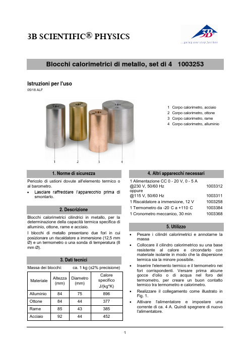
3B SCIENTIFIC ®PHYSICS1Istruzioni per l'uso05/18 ALF1 Corpo calorimetro, acciaio2 Corpo calorimetro, ottone 3Corpo calorimetro, rame 4Corpo calorimetro, alluminioPericolo di ustioni dovute all'elemento termico o al barometro.∙ Lasciare raffreddare l’apparecchioprima dismontarlo. Blocchi calorimetrici cilindrici in metallo, per la determinazione della capacità termica specifica di alluminio, ottone, rame e acciaio.I blocchi di metallo presentano due fori in cui posizionare un riscaldatore a immersione (12,5 mmØ) e un termometro o una sonda di temperatura (8 mm Ø). Massa dei blocchi:ca. 1 kg (±2% precisione)1 Alimentazione CC 0 - 20 V, 0 - 5 A @230 V, 50/60 Hz 1003312 oppure@115 V, 50/60 Hz1003311 1 Riscaldatore a immersione, 12 V 1003258 1 Termometro da -20°C a +110°C 1003384 1 Cronometro meccanico, 30 min 1003368∙ Pesare i cilindri calorimetrici e annotarne lamassa∙Collocare il cilindro calorimetrico su una base resistente al calore e circondarlo con materiale isolante in modo che la dispersione termica sia la minore possibile.∙Inserire l'elemento termico e il termometro nei fori corrispondenti. Versare prima alcune gocce d'olio o di acqua nel foro del termometro, per creare un buon contatto termico tra termometro e calorimetro.∙ Realizzare il collegamento come illustrato in Fig. 1.∙ Attivare l'alimentatore e impostare una corrente di ca. 4 A. Quindi spegnere di nuovo l'alimentatore.3B Scientific GmbH ▪ Rudorffweg 8 ▪ 21031 Amburgo • Germania ▪ Con riserva di modifiche tecniche © Copyright 2018 3B Scientific GmbH∙Attendere alcuni minuti prima di avviare l'esecuzione della misura. Leggere quindi la temperatura iniziale del cilindro calorimetrico. ∙ Accendere l'alimentatore econtemporaneamente avviare la misurazione del tempo.∙ Attendere fino a che la temperatura non èsalita fino a circa 20°C. Annotare tempo e temperatura finale.La capacità termica specifica è data dall'equazione:()12θ-θ⋅⋅=⋅⋅c m t U Icon I : corrente, U : tensione, t: tempo, m : massa del cilindro calorimetrico c: capacità termica specifica, θ1: temperatura iniziale, θ2: temperatura finale6.1 Indicazioni per la minimizzazione deglierroriAssunto che le indicazioni della corrente e della temperatura siano sufficientemente esatte, le due fonti principali di errore dell'esperimento stanno nella lettura della temperatura e nella dispersione termica.La dispersione termica dipende da quanto la temperatura finale è superiore alla temperatura ambiente. Essa può essere minimizzata grazie al fatto che l'incremento di temperatura viene mantenuto il più basso possibile.Se la precisione di lettura del termometro è pari a 1° C, risulta n errore relativamente grande del 10% in caso di un incremento di temperatura di 10° C.Pertanto si tratta di trovare un compromesso tra l'errore dovuto alla dispersione termica, in caso di un elevato incremento di temperatura, e l'errore relativamente grande nella lettura della temperatura in caso di un aumento della temperatura ridotto.Un aumento della temperatura di 20° C dà come risultato una percentuale di errore del 5% (con una precisione di lettura del termometro di 1° C) e un errore relativamente ridotto a causa della dispersione termica.6.2 Evitare la dispersione termica in base aRumford Secondo Rumford la dispersione termica può essere evitata mediante il seguente processo. Se il cilindro calorimetrico prima dell'esperimento viene conservato per alcune ore in un frigorifero, la sua temperatura iniziale rispetto alla temperatura ambiente è θ volte inferiore.Se in seguito allo svolgimento dell’esperimento la temperatura del calorimetro è θ superiore alla temperatura ambiente, la quantità di calore assorbita è pari alla quantità di calore che esso cede, fintantoché la sua temperatura non cala al di sotto della temperatura ambiente. Non avviene quindi nessuna dispersione termica.Fig. 1 Struttura sperimentale。
NOVOSTRICTIVE Transducer Touchless TM1 牵引传感器说明书

NOVOSTRICTIVETransducerTouchlessTM1Screw flangeCANopenIndustrialSpecial Features• Compact design for tight spaces• Touchless magnetostrictive measurement technology• Operating pressure up to 350 bar, peaks up to 450 bar• Non-contacting position detection with ring-shaped positionmarker• Unlimited mechanical life• No velocity limit for position marker• Absolute output• Outstanding accuracy performance up to 0.04 %• Wide range of supply voltage• Optimized for use in industrial applications• Other configurations see separate data sheetsApplications• Manufacturing Engineering• Level measurement• ActuatorsThe absolute linear transducer TM1 enables a compact and cost-effective position measurement. It consists of a stainless steel flange welded to a pressure-resistant rod and can therefore be used under harsh environmental conditions.The magnetostrictive measuring technology offers excellent accuracy for measuring lengths up to 2000 mm.The passive ring-shaped position marker allows a mechanically decoupled measurement.DescriptionMaterial Flange: SS 1.4307 / AISI 304LFlange cover: AlSiMgBiRod: SS 1.4571 / AISI 316TiSealing: O-ring NBR 90 SH AMounting Screwed via thread M18x1.5Electrical connection Connector M12x1, A-codedMechanical DataDimensions See dimension drawingSpecificationsCAD data seewww.novotechnik.de/en/download/cad-data/Technical DataType TM1-_ _ _ _-306-6_ _-106CANopenMeasured variables Position, speed and temperatureElectrical measuring range (dim. L)0 ... 50 mm up to 0 ... 2000 mmMeasuring range speed25 ... 1000 mm/sProtocol CANopen protocol to CiA DS-301 V4.2.0, Device profile DS-406 V3.2 Encoder Class C2, LSS services to CiA DS-305 V1.1.2 Programmable parameters Position, speed, cams, working areas, temperature, node ID, baud rateNode ID 1 ... 127 (default 127)Baud rate50 ... 1000 kBaudUpdate rate (output) 1 kHz (internal measuring rate 0.5 kHz)Resolution≤ 0.1 mmResolution speed 2 mm/sAbsolute linearity≤ ±0.04 %FS (min. 300 µm)Tolerance of electr. zero point±1 mmRepeatability≤ ±0.1 mmHysteresis≤ ±0.1 mmTemperature error≤ ±15 ppm/K (min. 0.01 mm/K)Supply voltage Ub12/24 VDC (8 ... 34 VDC)Supply voltage ripple≤ 10% UbPower drain w/o load< 1.5 WOvervoltage protection40 VDC (6 s)Polarity protection yes (supply lines and outputs)Short circuit protection yes (all outputs vs. GND and supply voltage)Insulation resistance (500 VDC)≥ 10 MΩBus termination internal w/o (internal load resistance 120 Ω on request)Environmental DataMax. operational speed Mechanically unlimitedVibration IEC 60068-2-620 g, 10 ... 2000 Hz, Amax = 0.75 mmShock IEC 60068-2-27100 g, 11 ms (single hit)Protection class DIN EN 60529IP67Operating temperature-40 ... +105°COperating humidity0 ... 95 % R.H. (no condensation)Working pressure≤ 350 barPressure peaks≤ 450 barBurst pressure> 700 barLife Mechanically unlimitedFunctional safety If you need assistance in using our products in safety-related systems, please contact usMTTF (IEC 60050)391 yearsTraceability Serial number on type labeling: production batch of the sensor assembly and relevant sensor componentsEMC CompatibilityEN 61000-4-2 ESD (contact/air discharge) 4 kV, 8 kVEN 61000-4-3 Electromagnetic fields (RFI)10 V/mEN 61000-4-4 Fast transients (burst) 1 kVEN 61000-4-6 Cond. disturbances (HF fields)10 V eff.EN 55016-2-3 Radiated disturbances Industrial and residential areaFS = Full scale: Signal span according to electrical measuring rangeZ-TH1-P18Ring position marker for fixation with screws M3 Material PA6-GFWeight approx. 12 gOperating temp.-40 ... +100°CSurface pressure max. 40 N/mm²max. 100 NcmFastening torqueof mountingP/N Pack. unit [pcs] 4000056971Z-TH1-P19Z-TH1-PD19 With spacerRing position marker for fixation with screws M4, optionally with or without spacerMaterial PA6-GF, Spacer: POM-GF Weight approx. 14 gOperating temp.-40 ... +100°CSurface pressure max. 40 N/mm²Fastening torque max. 100 NcmP/N Spacer Pack. unit[pcs] 400005698-1 400107117incl.1Z-TH1-P30Ring position marker for mounting via lock washer and retaining ringMaterial NdFeB bonded (EP)Weight approx. 5 gOperating temp.-40 ... +100°CSurface pressure max. 10 N/mm²P/N Pack. unit [pcs] 4001061391Z-TH1-P25U-shaped position marker for fixation with M4 screwsCaution: for dimension of electrical zero point please follow the user manual!Material PA6-GFOperating temp.-40 ... +105°CSurface pressure max. 40 N/mm²Fastening torquemax. 100 Ncmof mountingP/N Pack. unit [pcs] 4001050761Z-TH1-P32Ball-type floating position markerMaterial SS 1.4571 / AISI 316Ti Weight approx. 42 gOperating temp.-40 ... +100°C≤ 40 barCompressionstrengthDensity720 kg/m³Immersion depth36.7 mmin waterP/N Pack. unit [pcs] 4001057031Z-TH1-P21Cylinder floating position markerMaterial SS 1.4404 / AISI 316L Weight approx. 20 gOperating temp.-40 ... +100°C Compression≤ 8 barstrengthDensity740 kg/m³approx. 26.6 mm Immersion depthin waterP/N Pack. unit [pcs] 4000560441Floating Position Marker - Installation RecommendationWhen using floating position markers, we recommend to secure the marker against loss with a washer at the rod end.For this purpose, a sensor version with inner thread at the rod end is required (s. ordering code).Z-TH1-M01Lock nut ISO 8675, M18x1.5-A2P/N Pack. unit [pcs] 4000560901Connector SystemM12EEM-33-49/50/51M12x1 Mating female connector, 5-pin, straight, A-coded, with molded cable,IP67, shielded (shield on knurl), open ended Plug housing TPUCable sheath PUR, Ø = 6.7 mm,-25 ... +90°C (socket)-20 ... +80°C (cable)Lead wires PE, 2x0.25 mm²+2x0.34 mm²P/N Type Length 400106368EEM-33-49 2 m 400106371EEM-33-50 5 m 400106372EEM-33-5110 mEEM-33-52M12x1 Mating female/male connector, 5-pin, straight, A-coded, with molded cable,IP67, shielded (shield on knurl), CAN-BusPlug housing PURCable sheath PUR, Ø = 6.7 mm,-25 ... +90°C (plug/socket)-20 ... +80°C (cable)Lead wires PE, 2x0.25 mm²+2x0.34 mm²P/N Type Length 400106373EEM-33-52 5 mEEM-33-45M12x1 splitter / T-connector, 5-pin,A-coded, IP68,1:1 connection,female - male - female, CAN-BusPlug housing PUR, -25 ... +85°CP/N Type400056145EEM-33-45EEM-33-47M12x1 terminating resistor, 5-pin, A-coded,IP67, 120 Ω resistance, CAN-BusPlug housing PUR, -25 ... +85°CP/N Type400056147EEM-33-47Novotechnik U.S., Inc.155 Northboro RoadSouthborough, MA 01772Phone 508 485 2244Fax 508 485 2430********************© Jul 18, 2022The specifications contained in our datasheets are intended solely for informational purposes. The documented specification values are based on ideal operational and environmental conditions and can vary significantly depending on the actual customer application. Using our products at or close to one or more of the specified performance ranges can lead to limitations regarding other performance parameters. It is therefore necessary that the end user verifies relevant performance parameters in the intended application. We reserve the right to change product specifications without notice.。
RESIST PATTERN FORMING METHOD AND RESIST TREATING

专利名称:RESIST PATTERN FORMING METHOD AND RESIST TREATING APPARATUS
发明人:KIRITA KEI,KATOU YOSHIHIDE,SHINOZAKI T OSH IAKI
申请号:JP1185784 申请日:1984 0127 公开号:J P S60157224 A 公开日:19850817
申请人:TOSHIBA KKPURPOSE:To increase the sensitivity of a resist and to form a high-precision resist pattern, by baking the resist at the temperature above the glass transition temperature and by cooling it rapidly and uniformly with a liquid coolant under specified pressure, after pattern exposure and before developing process. CONSTITUTION:A resist film is coated on the substrate to be treated, is then pre-baked and is normally cooled. After a pattern is exposed to the resist film, the resist film is baked at the temperature Tb above the glass transition temperature Tg of the resist (baking before developing). Next, it is cooled rapidly with uniform temperature distribution over the entire resist film, by immersing the resist film into liquid coolant with temperature Tc under a pressurized state whose boiling point is in excess of the temperature Tb. In this case, the sensitivity of the resist can be controlled at any value depending on the temperature difference Tb-Tc (Tb>Tc) at the rapid cooling. Thereafter, developing and rinsing process is done to form a resist pattern.
DIAGNOSTIC REAGENT

更多信息请下载全文后查看
专利内容由知识产权出版社提供
专利名称:DIAGNOSTIC REAGENT 发明人:MITANI KAT0507 公开号:JPS60235061A 公开日:19851121
摘要:PURPOSE:To obtain a diagnostic reagent excellent in sensitivity and rapidity, by immobilizing an immunologically active substance by adsorbing the same by a polymer having a specific compositional ratio consisting of a structural unit having a hydrophobic group and a structual unit having a dihydroxy group. CONSTITUTION:A monomer having a structural unit represented by formula I (wherein R1 is a hydrogen atom or an alkyl group and R2 is a hydrophobic group), for example, styrene or methylmethacrylate and a monomer having a structural unit represented by formula II (wherein R is a hydrogen atom or an alkyl group), for example, glycidyl methacrylate or 2,3-dioxymethacrylate are polymerized. The structural unit represented by the formula I has a hydrophobic group and a compositional ratio containing 0.3-20mol% of the structural unit having a dehydroxy group represented by the formula II is obtained. Because the obtained polymer particle has a hydrophilic group and a hydrophobic one in a well balanced state, a diagnostic reagent having excellent sensitivity, rapidity and stability to antigen-antibody reaction can be obtained if an immnologically active substance is adsorbed and immobilized.
Plate-like multiple antenna and electrical equipme
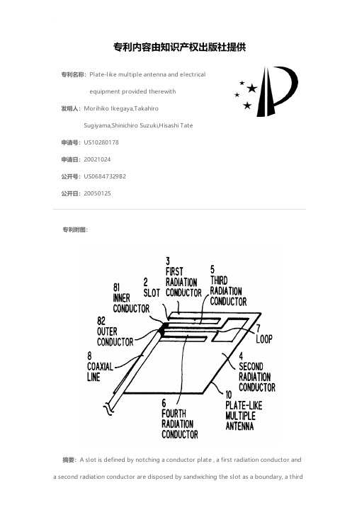
radiation conductor connected to either of the first radiation conductor or the second radiation conductor is provided in the slot , if necessary, on and after third radiation conductors, for example, a fourth and fifth radiation conductors connected to either of the first radiation conductor or the second radiation conductor are provided, a power is supplied in the slot by the use of conductor edges of at least two radiation conductors, if required, whereby two monopole antennas and slot antennas, which use respective electric currents on the first radiation conductor and the second radiation conductor , are electrically formed, besides, antennas other than that described above are electrically formed by utilizing electric currents over on and after the third radiation conductors.
CONTROLLING METHOD OF EVAPORATION RATE
更多信息请下载全文后查看
专利ห้องสมุดไป่ตู้容由知识产权出版社提供
专利名称:CONTROLLING METHOD OF EVAPORATION RAT E
发明人:NAKAGAWA YOSHIKIYO 申请号:JP21707182 申请日:19821213 公开号:JPS59107075A 公开日:1984 0621
摘要:PURPOSE:To control the evaporation rate of a plating metal and to perform plating to a uniform thickness by controlling the surface level of the plating metal bath contained in the vessel of a vapor source, detecting the temp. of the bath surface and regulating the output of a heater for heating the plating bath. CONSTITUTION:An electrical signal circuit is formed of an electrode 15 immersed in a plating metal bath 3, an electrode 16 installed on a bath surface level 9 and a power source 17. When electric current flows through the level 9 between the electrodes 15 and 16, the signal is received by a relay circuit 18 which moves downward the top end 22 in the upper part of a hydraulic type lifting device 21. When the current does not flow through the level 9, the device 21 is moved upward whereby the level 9 is controlled constant. The top end of a thermocouple 11 is installed at the same level as the top end of the electrode 16 and the temp. on the bath surface is always detected. The output of a heater 14 is adjusted by a temp. controller 12 and a power source 13 whereby the temp. of the bath surface 9 is maintained constant.
RADIATOR
专利名称:RADIAT OR 发明人:ONISHI TETSUO,SATO HITOSHI,KIKUCHI
KOICHIRO 申请号:JP28598286 申请日:19861202 公开号:J P S63994 95A 公开日:198804 30
摘要:PURPOSE:To improve a thermal transmittance characteristic and enable a smallsized, thin type, light weight unit to be provided without decreasing an anti- clogging characteristic or a strength by a method wherein each of fin plates of a radiator is provided with projections for promoting disturbance flow on the fin plates. CONSTITUTION:Several fin plates 2 passing through and fixed to tubes 1 in an air flowing direction are provided with projections 3. The projections 3 are provided on a central line 4 of inter-tube passage and a crossing point of the line 4 with a center line 5 between tubes arranged in a flowing direction, or at positions displaced from the center line 5 between the tubes to each of the tubes. A height of each of the projections 3 is about 1/4-2/3 of a spacing between the fin plates 2 and a sectional shape of each of the projections 3 is a water drip shape, a conical shape, a mountain-like shape of a pyramid shape and the like. With this arrangement, air flowing between the fins is agitated, a thermal transmittance characteristic can be improved without decreasing anti-clogging or strength characteristic and so a small-sized, a thin and a light weight unit can be attained.
- 1、下载文档前请自行甄别文档内容的完整性,平台不提供额外的编辑、内容补充、找答案等附加服务。
- 2、"仅部分预览"的文档,不可在线预览部分如存在完整性等问题,可反馈申请退款(可完整预览的文档不适用该条件!)。
- 3、如文档侵犯您的权益,请联系客服反馈,我们会尽快为您处理(人工客服工作时间:9:00-18:30)。
气囊 电缆 电子接口模块 电子接口
Orbit®3 控制器接口类型 读取速率 电子带宽(Hz) 用户可选 功率
单片式挠性规 DUS/0.5/S DUSB/0.5/S 6
+5 to +80
EN61000-6-3
EN61000-6-2
请尽量避免过度冲击 或 负载
大于1亿次 (取决于具体的应用)
17-7 不锈钢 (耐腐蚀型)
不锈钢
M3 螺纹 或 M3 Heli 螺套 (适合安装M3
Issue number: 17/01
Datasheet number: 503385-CN
2
单片式挠性规 - 电缆结构 及 操作方向
正常操作(压簧)
0.5 毫米
0.5 毫米
DUS/0.5/S AUS/0.25/S
反向操作(拉簧)
DUSB/0.5/S AUS/0.25/S
0.5 毫米
0.5 毫米
Direction of movement
DUSM 迷你单片挠性规 – 测量范围为 0.5 毫米, IP 68 防护等级, 多种测头配置 可选
应用案例:采用单片式挠性规检 测曲轴外径
应用案例:采用迷你单片挠性规进行发动机缸孔 的内径测量,能胜任恶劣的环境中检测
成功案例: 行业: 汽车, 军工 车辆: 布拉德利装甲战车平台 应用: 变速箱轴承套检测 使用的产品: DUS
标准的单片式挠性规提供Orbit 数字接口类型(DUS/0.5/S) 和 模拟式 LVDT (AUS/0.25/S)两种型号 DUS 和 AUS 可以在订购的时候选择不同操作方向或电缆出线的产品,同时也可以选择 可调式测头
增加延长臂的单片式挠性规示例图
使用多个拉簧类型的单片式挠性规在应 用延长臂的情况下进行轴圆度和跳动的 测量应用示意图
Issue number: 17/01
Datasheet number: 503385-CN
6
尺寸图 - DUSM 尺寸图பைடு நூலகம்- DUSM 高度可调测头
Issue number: 17/01
Datasheet number: 503385-CN
7
性能规格 – 单片式挠性规 和 迷你式单片挠性规
产品 旁向出线电缆类型 底部出线电缆类型 壳体宽带(毫米) 测量性能规格 测量范围 (毫米) (备注 3) 精度 (% 读数的百分比) (备注 1) 重复性 (微米) (备注 2) 分辨率 (微米) 预行程 (毫米) 后行程(毫米) 测量中间位置测力大小 (N)
Issue number: 17/01
Datasheet number: 503385-CN
1
DUS 单片式挠性规
特性 ►0.5 毫米测量范围 ►Orbit 数字接口类型,易用且精度极佳 ►弹簧驱动类型(压簧和拉簧两种结构) ►IP65 防护等级 – 耐腐蚀不锈钢壳体 ►可使用延长臂
产品描述
单片式挠性规很容易安装,仅仅与被测量产品有少许接触力即可完成移动部件的轮廓的 精密测量,譬如旋转轴、刹车盘等。继输力强(Solartron)广受好评的平行式挠性规之后 推出的单片式挠性规满足了测量设备集成商更多密集测量点的需求。 使用延长臂的情况 下可以进行键槽内部尺寸的检测,还能使用于传统笔式传感器无法使用的场合。
DUSM 检测多种深度 下的内径尺寸检测应 用示意图
. 应用案例: 集成于多通道无线 孔径规内部的 DUSM 进行内孔 直径的无线检测
Issue number: 17/01
Datasheet number: 503385-CN
5
DUSM 测头类型
0.5 毫米 移动方向
DUSM 高度可调测头
详细请参考尺寸图
迷你式单片挠性规 DUSM/0.5/S N/A 7
0.5 0.1 <0.1 0.01 0.02/0.03 0.05/0.1
0.9/1.56
0.5 0.05 <0.1 0.01 0.01/0.02 0.07
0.27/0.83
IP65
IP68
IP43 (T-CON和模块)
-20 to +80
+5 to +60
DUS/0.5/R AUS/0.25/R
DUSB/0.5/R AUSB/0.25/R
Issue number: 17/01
Datasheet number: 503385-CN
3
尺寸图 DUS 及 AUS 系列
Issue number: 17/01
Datasheet number: 503385-CN
单片式挠性规
全新系列的挠性规测量传感器
► 常规传感器难以企及的内孔或间隙尺寸的 精密检测
► 极佳的分辨率和重复性性能 ► 坚固型壳体设计,优异的抗侧向力性能 ► 潜在应用: 发动机零部件, 曲轴, 缸孔, 狭小
孔径的尺寸检测
► 应用市场: 汽车, 农业, 重工业
DUS 单片式挠性规. 0.5 毫米测量范围, 优异的抗侧向力性能,极佳的分辨率
4
DUSM – 迷你式挠性规
►精度 小于1 微米 ►优异的重复性 <0.5 微米 ►测量范围 0.5 毫米 ►IP68 防护等级 ►多种测头类型可配置 ►牢固的结构设计,紧凑尺寸
迷你式单片挠性规是基于弹性体结构接触式传感器的另一种变型体 设计,测量范围为0 – 500 微米,提供多种可配置型测头
传感器使用单个的 M2.5 螺钉进行固定,接触测头可以安装在拥有 自锁功能的 M3 螺套内,主要适用于接触测头扩展使用。也可以使 用OEM自己定制的固定长度接触头或 Solartron’s 测头适配器(能够 有0.5mm的高度调整范围), OEM 所定制的测头,建议其高度不要 超过探头上表面6毫米以内为宜,以免降低传感器的重复性性能及 使用寿命。传感器中间位置为使用标准测头校准时的参考点。
在某些场合可以使用延长臂,但是使用时务必小心谨慎。接触点与 安装螺纹处的距离最好小于12 毫米为宜,但是具体情况要考虑测 头高度倾角及测量变形大小 – 极端情况下会大幅缩短传感器的寿命 以及使传感器的重复性性能降低几个等级。使用延长臂后,传感器 的读数必须进行系数修正,以免影响测量精度。具体的修正系数跟 使用的延长臂尺寸有关。