富士工业超声波浓度计(中文)
浓度仪产品说明书

1pH/MV/TEMP HANDHELD METER WITH RS232 CAPABILITYߜDual LCD Display ShowspH / °C or °F or mV / °C or °F ߜMax / Min, Rec.ߜRS232 Data Output ߜAuto Power Off in20 Minutes, Disable Sleep ModeߜLow Battery IndicatorThe PHH-860 pH/mV/temperature meters are excellent foraquaculture, sanitation plants, water and wastewater treatment plants.The PHH-860 features RS232communication and an optional software package is available for ease of use.These microprocessor based digital meters are rugged, portable units which are able to recognize and compensate for electrode offset and slope. The PHH-860 also features hold, relative and average functions.FEATURES:ߜSlope Control: Yes ߜDisplay: 4 Digit ߜMax./Min., RECߜBattery low indicator ߜCalibration up to 3 (pH 4.01, 7.01, 10.01)ߜEpoxy-body combination pH electrodeߜOperating humidity max. 80% RH ߜAuto power off in 20 minutes,disable sleep modeߜDual LCD display shows pH/°C &°F or mV/°C & °FSPECIFICATIONSMeasuring Range: pH: 0.00 to 14.00mV: ±499. -5 to 80°C Accuracy: pH: ±0.02 pHmV: ±0.2 mV (0.1 to 180.0 mV), ±2 mV (181 to 499 mV)Temp: ±0.3°CResolution: pH: 0.01mV: 0.1 mV ±(0.1 to 180.0 mV)1 mV ±(181 to 499 mV)Temperature Compensation:-5 to 80°C (23 to 176°F)Operating Temperature:0 to 50°C (32 to 122°F)Operating Humidity: Max 80% RH Input Impedance:1012ΩDisplay:4 Digit LCDpH Electrode Connection:BNCPower Input:9V Battery (Included) or Optional dc Power AdaptorData Output:RS232 Serial interfaceRS232 Format: Band Rate: 2400Bit/sec, Data Bits:8 Stop Bits:1Dimensions:72 x 182 x 30 mm (meter)(2.8 x 7.2 x 1.2")Weight: 220 g (7.8 oz) (with Battery)PHH-860$300To Order (Specify Model Number)Unit comes with hard carrying case electrode 4, 7, 10 Buffer Solutions battery and complete operator’s manual.Ordering Example: PHH-860handheld meter, PHH-860-SW software and cable,$300 + 75 = $375Shown with Optional Software and Cable Accessories.Electrode IncludedCANADA www.omega.ca Laval(Quebec) 1-800-TC-OMEGA UNITED KINGDOM www. Manchester, England0800-488-488GERMANY www.omega.deDeckenpfronn, Germany************FRANCE www.omega.frGuyancourt, France088-466-342BENELUX www.omega.nl Amstelveen, NL 0800-099-33-44UNITED STATES 1-800-TC-OMEGA Stamford, CT.CZECH REPUBLIC www.omegaeng.cz Karviná, Czech Republic596-311-899TemperatureCalibrators, Connectors, General Test and MeasurementInstruments, Glass Bulb Thermometers, Handheld Instruments for Temperature Measurement, Ice Point References,Indicating Labels, Crayons, Cements and Lacquers, Infrared Temperature Measurement Instruments, Recorders Relative Humidity Measurement Instruments, RTD Probes, Elements and Assemblies, Temperature & Process Meters, Timers and Counters, Temperature and Process Controllers and Power Switching Devices, Thermistor Elements, Probes andAssemblies,Thermocouples Thermowells and Head and Well Assemblies, Transmitters, WirePressure, Strain and ForceDisplacement Transducers, Dynamic Measurement Force Sensors, Instrumentation for Pressure and Strain Measurements, Load Cells, Pressure Gauges, PressureReference Section, Pressure Switches, Pressure Transducers, Proximity Transducers, Regulators,Strain Gages, Torque Transducers, ValvespH and ConductivityConductivity Instrumentation, Dissolved OxygenInstrumentation, Environmental Instrumentation, pH Electrodes and Instruments, Water and Soil Analysis InstrumentationHeatersBand Heaters, Cartridge Heaters, Circulation Heaters, Comfort Heaters, Controllers, Meters and SwitchingDevices, Flexible Heaters, General Test and Measurement Instruments, Heater Hook-up Wire, Heating Cable Systems, Immersion Heaters, Process Air and Duct, Heaters, Radiant Heaters, Strip Heaters, Tubular HeatersFlow and LevelAir Velocity Indicators, Doppler Flowmeters, LevelMeasurement, Magnetic Flowmeters, Mass Flowmeters,Pitot Tubes, Pumps, Rotameters, Turbine and Paddle Wheel Flowmeters, Ultrasonic Flowmeters, Valves, Variable Area Flowmeters, Vortex Shedding FlowmetersData AcquisitionAuto-Dialers and Alarm Monitoring Systems, Communication Products and Converters, Data Acquisition and Analysis Software, Data LoggersPlug-in Cards, Signal Conditioners, USB, RS232, RS485 and Parallel Port Data Acquisition Systems, Wireless Transmitters and Receivers。
XSS1000超声波污泥浓度说明书
安装方法:
可伸缩不锈钢支架 支架固定座 池壁
φ25连接件 固定底座
在池顶部适当位置打入两个 M8 钢
制膨胀螺栓。(尺寸见附录 1)
φ25PP-R 连接(如左图所示或见附录 4)
传感器线缆 φ25连接件
将传感器电缆依次穿过连接套管; 将传感器的螺纹与连接套管的螺纹
孔相接并拧紧且需密封处理;
PP-R 连接套管按顺序依次连接;
超声波污泥浓度计
备注 电流输出 屏蔽线(浸没式) 黑线(浸没式)
红线(浸没式)
自动清洗 AC220V AC220V
大地
10
控制面板
四、调
①
MENU 键,选择工作模式
②
SET 键,执行工作和记忆设定数值
③
RUN 键,进入运行模式,退出设置模式
④
UP 键,增加数字
第二章 产品 变送器 ................................................................................. 3 传感器 ................................................................................. 3
1
超声波污泥浓度计 时间显示,可设时间间隔自动记录浓度变化趋势线。 可选现场总线接口。
产品 应用
给水厂及污水处理厂: 回流污泥、初沉池、二沉池、浓缩池、污泥脱水等。
工矿企业: 洗煤厂、矿山、造纸、电力矿浆浓度、煤浆浓度、 灰浆浓度、纸浆浓度等。
2
变送器 传感器
二、产 品
超声波污泥浓度计
技术参数: 测量范围:污泥:0~10%
SU超声波说明书
以下情况不在免费保修范围内:
z
产品或其部件已超出免费保修期。
z
因使用环境不符合产品使用要求而导致的硬件故障。
z
因不良的电源环境或异物进入设备所引起的故障或损坏。
z
由于未能按使用操作手册上所写的使用方法和注意事项进行操作而造成的故障。
z
由于不可抵抗力如:雷电、水火灾等自然因素而造成的故障。
擅自拆机修理或越权改装或滥用造成的故障或损坏。
spesspescomcnsu系列二线制用户手册上海思派电子科技有限公司超声波液位计su超声波液位计su超声波液位计保修卡回执用户名称联系地址联系人联系电话产品型号产品编号验收日期安装负责人su超声波液位计保修卡说明产品型号产品编号验收日期安装负责人保修政策
SU 系列二线制 超声波液位计
用户手册
上海思派电子科技有限公司
2
SU 超声波液位计
3.3 安装参数含义
SU 超声波液位计
3.5 安装注意事项 1)仪表在室外安装建议加装遮阳板以延长仪表使用寿命。 2)电线、电缆保护管,要注意密封防止积水。 3)仪表虽然自身带有防雷器件,但仪表在多雷地区使用时,建议在仪表的进出线端另外
安装专用的防雷装置。 4)仪表在特别炎热、寒冷的地方使用,即周围环境温度有可能超出仪表的工作要求时,Fra bibliotek限制说明:
z 请用户妥善保存保修卡作为保修凭证,遗失不补。
本保修卡解释权限归本公司所有,本公司有权对本卡内容进行修改,恕不事先通知。
SU 超声波液位计
目录
1 概述……………………………………………………………………………………….1 2 技术指标…………………………………………………………………………………1 3 仪表安装………………………………………………………………………………….2 3.1 仪表外形尺寸…………………………………………………………………………2 3.2 仪表接线………………………………………………………………………………2 3.3 安装参数含义…………………………………………………………………………3 3.4 仪表安装原则…………………………………………………………………………3 3.5 安装注意事项…………………………………………………………………………4 4 仪表调试…………………………………………………………………………………. 4 4.1 键盘说明 …………………………………………………………….…….…………4 4.2 密码说明 …………………………………………………………….…….………... 4
USCII超声波硫酸浓度分析仪
USCII超声波硫酸浓度分析仪USC-II超声波硫酸浓度分析仪使用说明书南化集团研究院目录1 工作原理2 主要技术参数3 仪器特点4 仪器结构5 仪器安装,使用及调试6 常见故障及排除方法7 仪器的成套8 本仪器在水中特性93%硫酸是化工生产及医药生产的重要原料.在硫酸生产系统中作为干燥酸,直接影响着进入转化器的SO2气体的含水指标.生产中需要有一种正确,连续,可靠的在线测量93%硫酸浓度仪表.国内已有应用沸点法,比重法,谐振法的93%硫酸浓度仪,现在我们根据干吸工序腐蚀性强的特点,推出一种新颖的非接触式的超声波硫酸浓度仪.早在六十年代,超声工业测量技术就十分盛行,由于当时与它配套的一, 工作原理本仪器是根据超声脉冲波在介质中传播和反射原理构成.计算机发射一脉冲,放大后传输给超声换能器,电脉冲在换能器上转换超声波传到反射板扫射回来,通过超声换能器又转换成电讯号.从发射脉冲和反射回来的超声脉冲时间差S,可得出声速见图1,当溶液在固定的容器中流动时,声速度与被测溶液的浓度和温度有关.被测介质出口即:C=f(J,t)式中:J—声速超声波反射 L 超声波发射 t—溶液温度c—溶液浓度被测介质入口图1根据文献提供的数据,曲线及实验室测试的浓度声时数据表明,硫酸浓度每变化1%,将引起19米/秒的声速变化,显然灵敏度是高的.由实验数据,进行多项回归:C=f(J,t)=a0+a1(J-J0)+a2(J-J0)2+a3(t-t0)+a4(t-t0)2+a5(J-J0)×(t-t0) 这样,当测得声速和温度后,就可以计算出浓度值.二,主要技术参数1,测量范围: 91%~95%硫酸(可调)2,温度补偿范围: 40℃±30℃3,精度测量: ≤±5%(相对误差)4,输出信号: 4~20mADC5,负载电阻: 0~800Ω6,环境温度: -10℃~45℃7,供电电压: 220±10%V AC8,功率消耗: <30W三,仪器特点仪器现场部份为全封闭管道安装式.结构简单,性能可靠,不受测量介质的腐蚀,大大提高了仪表的使用寿命,维护量小.通过光隔实现了输入,输出的隔离,消除了诸如大电流跳动所引起的的干扰,并能克服高共模电压,大大地提高了仪表抗干扰能力.选用具有较强数据和逻辑处理能力,应用广泛的MCS-51图2仪器结构示意图检测器结构检测器为流通式检测器.(其结构见图3a~3b)图3a流通式检测器结构图图3b流通式检测器安装法兰图检测器由采样板,换能器,测温管等组成.换能器是实现声时—电转换的主要部件,通常是采用压电陶瓷材料制做换能器,压电陶瓷是一种具有压电效应和逆压电效应的陶瓷材料.当它受力作用时,会产生电信号,反之当它受到电场作用时,会产生应力和应变,利用压电陶瓷的这个特性,人为地对它施加一个脉冲电压,使其产生超声振动(即超声波的发射),当超声波反射波返回到达压电陶瓷上时,由于声压的作用,它会产生脉冲电势.这样实现了电—声,声—电的转换.采样板作用是进行温度,声时采样,采样板上带CPU图4采样线路框图由CPU发出的声时触发信号,经整形后,触发发射电路,激发压电陶瓷晶片,使其发生振荡,产生超声波,超声波从换能器发出,经溶液到反射面,反射回来的回波被晶片接收,经放大整形后,送脉宽转换电路,得到与浓度,温度有关的脉冲宽度,经计数电路后,再转换成串行数据,传送给信号处理器.同样,由CPU发出的温度触发信号,经整形后,触发由AD590组成的温度-脉宽转换电路送至计数电路后,转换成数字串行信号传送给信号处理器.由于声时测量和温度测量是分时交替进行的,所以两个通道共用一个计数器电路,24M振荡器,串行信号转换,发送电路是公用的.2,信号处理器结构信号处理器是根据检测器传送过来的声时及温度信号,计算出硫酸浓度,分别送显示和输出,其框图见图6.图6 信号处理器框图①计算机组成信号处理器以ATMEL 89C52为CPU,X5045P E2PROM为数据存贮器,四位键盘为"切换","确认","增加","减少",四位LED显示用来显示浓度和温度等工作状态.②信号接收,处理信号处理器接收信号检测器以串行数据方式送来的温度和声时数据,并对其进行计算和处理,然后送四位LED显示.③输出电路由计算机输出浓度对应的脉宽信号,经光隔后,通过脉宽-电流转换器,输出4~20mA电流信号.④报警电路当温度或声时采样数据异常时,计算机输出信号触发达林顿管,注:(1)图中标示的"检测器出口流量控制阀"必须安装;(2)仪表正常使用时,"排污截止阀"必须关闭.图12信号处理器外形尺寸及开孔尺寸图13 USC型检测器与信号处理器接线图(二)仪器的使用① 开机仪器安装正确后,关闭检测器下部排污阀,缓缓开启取样阀,使检测器的测量槽内充满酸,流量不宜过大,如仪器第一次使用,或大修停机较长时间,检测器探头在酸中需充分钝化,这需等待一小时左右.然后再接通仪器电源,仪器即显示温度值,过几秒后自动跳转到浓度显示.同时信号处理器输出对应酸浓信号.② 按键说明信号处理器面板有四只按键,分别为"切换"键,"确认"键,"增加"键和"减少"键,其中"切换"键为显示切换,每按一下"切换"键显示窗口将由酸浓显示转换为温度显示,或由温度显示转换为酸浓显示.几秒钟不按键,仪器自动切换为酸浓显示."确认"键有二个作用,分别为修改确认和进入调试状态."增加"键和"减少"键在仪表调试状态使用 .③ 报警说明当接收数据超限时,仪器将自动用面板上的二个指示灯显示报警状态,并接通报警触接点.④ 维护说明仪器因工艺停车,长时间(10天以上)无采样酸流动情况下,应将流通式检测器的铸铝防护罩连同换能器,采样器一起从测量槽中拆除保养,待再使用时按要求重新安装接线.(注:铸铝件和测量槽紧固的4只螺栓切勿用力太大,避免接裂铸铝法兰). (三)调试按住"确认"键10秒左右,仪器将进入调试状态.按"切换"键,仪器将交替显示"P- -0"~~ P- -9"及其相对应的参数,其所代表的参数如下表所示:符号对应的参数正常值P- -0浓度校正91.00---95.00P- -1温度校正c10.00---c90.00P- -2输出电流零点o---04P- -3输出电流量程o---20P- -4下限报警91.00(可调)P- -5上限报警95.00(可调)P- -6声速校正1380左右P- -7回波个数3---10P- -8声时测量值9999---5000P- -9温度测量值常温下2000左右浓度校正当仪器交替显示'P- -0'和浓度值时,按"增加"键或"减少"键,可实现浓度校正.温度校正当仪器交替显示'P- -1'和温度值时,按"增加"键或"减少"键,可实现温度校正.输出电流零点当仪器交替显示'P- -2'和'o- 04'时,按"增加"键或"减少"键,可实现输出电流零点校正(4mA).输出电流量程当仪器交替显示'P- -3'和'o- 20'浓度值时,按"增加"键或"减少"键,可实现输出电流量程校正(20mA).下限报警设定当仪器交替显示'P- -4'和下限报警值时,按"增加"键或"减少"键,可实现下限报警设定.上限报警设定当仪器交替显示'P- -5'和上限报警值时,按"增加"键或"减少"键,可实现上限报警设定.其余参数用户不要修改,以免影响仪器的正常测量.⑩ 修改结束后,按"确认"键退出修改.○11X5045P存储器数初始化,在仪表送电前同时按下"增加"键和"减少"键.然后送电,这时仪表指示"EEEE".大约10秒钟后仪表关电后重新开电即可.六,常见故障及排除方法仪器出现故障时可按以下顺序检查1仪器通电检查顺序现象原因排除方法1.显示器不亮,仪器不工作电源没有接好,仪表后部插头松动检查供电电源是否正常,抽出仪器芯,重新插好插座2 检查仪器显示温度是否符合要求.这温度要求是指仪器显示与实际被测介质温度之间的关系,实际被测介质温度可以用玻璃温度计测量也可根据经验估计.如仪器显示与实际相符则进入下一节"超声接收信号是否正常"检查,如不一致,则进入仪表调试状态,按下表顺序检查顺序现象原因排除方法1在P-9状态下,指示值在正常范围,但温度指示为0000,或异常数据X5045P存储器内数据不正常①重新对X5045存储器数初始化②在P-1状态下,通过面板操作进行调整③与生产厂家联系2在P-9状态下,指示值为0000①AD590损坏或接线有误②现场检测器与信号处理器之间的串行数据通信线有问题③温度通道不正常或LM555损坏①检查AD590接线或更换AD590②检查现场检测器与信号处理器之间的接线③更换LM555,或与生产厂联系3显示温度与实际不符,有一定差距AD590 有误差在P-1状态下,通过面板操作进行调整4显示温度有0.5度以上跳动接地不好信号处理器7#接地端是否接地,或通过屏蔽层与现场检测器外壳相连3超声接收信号是否正常超声接收信号是否正常决定仪表能否正常工作,如发现浓度无指示或指示异常,可进入仪表调试状态,按以下顺序检查顺序现象原因排除方法1浓度指示异常,在P—7状态下回波数少于三个硫酸没有充满测量槽或没有酸流过测量槽,换能器接线没有接好,或换能器和反射板故障没有按照要求安装检测器.检测器线路板故障现场检测器与信号处理器之间的串行数据通信线有问题①关小出口阀,全开进口阀,调出口阀有合理酸流量②将换能器连线重新接好,并检查换能器和反射板③按照要求安装检测器.④检查检测器线路板故障或与生产厂家联系⑤检查现场检测器与信号处理器之间的接线2浓度指示跳动,P—7状态下回波数大于三个,P-6指示跳动, 被测介质中有气泡开大进口阀,进一步关小出口阀3浓度指示异常,P—7状态下回波数大于三个,P-6指示异常数据存储器内数据不正常①重新对X5045存储器数初始化②在P-6状态下,通过面板操作进行调整③与生产厂家联系4显示浓度与实际不符,有一定差距仪器有误差在P-0状态下,通过面板操作进行调整5温度和浓度数据均没有①检测器与信号处理器之间通信线没接好②现场干扰大③线路板故障①检查检测器与信号处理器之间通信线②将屏蔽层接地③与生产厂家联系4 没有电流输出顺序现象原因排除方法1没有输出信号①外联仪表故障或外联接线有问题②输出电路OP07损坏①检查外联仪表或外联接线②更换OP07功放5 仪器走死线指仪器输出不随酸浓变化而变化顺序现象原因排除方法1仪器走死线,输出电流不变化①被测酸不流动②输出电路OP07损坏③软件或硬件故障①调节放酸量,保证取样槽中有酸流动②更换OP07功放,或与厂家联系③重新送电或与生产厂家联系七,仪器的成套整套仪器包括:⑴信号处理器一台(包括安装托架一付);⑵检测器一台⑶说明书一份⑷测量槽一个附::本仪器在水中的特性,由于硫酸在作为标准物质标定本仪器时有一定的危险性,可以用蒸馏水代替硫酸对本仪器的以下某些性能进行标定.在用水代替硫酸进行试验时,可用一个烧杯装入适量的蒸馏水,将分析仪倒插入烧杯中,如图所示.注:蒸馏水要充满烧杯,在传感器与蒸馏水之间不能有空隙.P—1:温度校正水的温度与仪器在此状态下的指示温度一致,这是对仪器温度信道的检测,如仪器指示与水的实际温度不一致,可按P—1的调整方法调整.水的实际温度可用玻璃温度计测量.P—6:声速校正不同温度下超声波在水中传播速度是不一样的,不同温度下超声波在水中传播速度如表所示,如仪器在此状态下的指示值与表格的数据不一至,可以按P—6的调整方法调整,使其指示值与表格的数据一至.此项调整可替代仪器在硫酸介质中的量程调整.超声波在蒸馏水中传播速度温度2025303540455055声速1482.71497.01509.41519.71529.21536.41542.91547.2P—7:超声波接受回波个数由于传感器及电子线路对温度的敏感性,当仪器在不同环境温度时,其可以接受到的反射回波数是不一样的,环境温度越高,反射回波数越少.在常温下一般要求反射回波数大于3个,如发现小于3个,须对放大电路或传感器进行适当调整,也可以与生产厂家联系.单位:南化集团研究院仪表自动化研究所地址:南京市大厂区葛关路699号邮编:210048电话:025-********025-********USC-Ⅱ超声波硫酸浓度分析仪使用说明书南化集团研究院仪表及自动化研究所信号处理器检测器晶片整形整形发射电路温度脉宽转换放大整形脉宽计数器振荡器串行信号转换,输出集电极开路声时触发信号温度触发信号串行数据输出计算机三位键盘光隔四位显示光隔脉宽-电流转换报警电路输出4-20mA串行数据图11 流通式检测器现场安装示意图串行数据供电。
Pepperl+Fuchs UC4000-30GM-IUR2-V15 超声传感器产品说明书

UC4000-30GM-IUR2-V15Ultrasonic sensorUC4000-30GM-IUR2-V15R e l e a s e d a t e : 2018-01-08 10:27D a t e o f i s s u e : 2018-01-09104094_e n g .x m lDimensionsElectrical ConnectionPinoutTemperature probeCoded plug52225128ø40M30x1.527.536LEDStandard symbol/Connection:(v ersion IU)Sync.Core colors in accordance with EN 60947-5-2.0-10 V 4-20 mA + U B - U B15432(BN)(GY)(BK)(BU)(WH)U134521 BN2 WH3 BU4 BK 5GYWire colors in accordance with EN 60947-5-2(brown)(white)(blue)(black)(gray)Additional Information Analogue output functionNear distance of evaluation Far distance of evaluationAnalog functionRising slopeFalling slopeZero line mode20 mA/10 V4 mA/0 V4 mA/0 V 20 mA/10 V20 mA/10 V4 mA/0 VA1= 0 mmA2R e l e a s e d a t e : 2018-01-08 10:27D a t e o f i s s u e : 2018-01-09104094_e n g .x m l Description of Sensor FunctionsProgramming procedureThe sensor features 2 programmable analog outputs with programmable evaluation range. Programming the evaluation range and the operating mode is done either via the sensor's RS232 interface and ULTRA3000 software (see the ULTRA3000 software description) or by means of the programming plug at the sensor's back end which is described here.Programming of Evaluation Range1.Disconnect supply voltage2.Remove the programming plug to activate program mode.3.Reconnect supply voltage (Reset)4.Place the target at the desired position for A15.Momentarily insert the programming plug in position A1 and then remove. This will program the position A1.6.Place the target at the desired position for A27.Momentarily insert the programming plug in position A2 and then remove. This will program the position A2.Notes:•Removing the programming plug saves the new position into the device memory.•The programming status is indicated by the LED. A flashing green LED indicates that the target is detected; a flashing red LED indicates that no target is detected.Programming the Operation ModeIf the program mode is still activated, continue at number 4. If not, activate program mode by performing the sequence numbers 1 to 3.1.Disconnect supply voltage2.Remove the programming plug to activate program mode.3.Reconnect supply voltage (Reset)4.Insert the programming plug in position E2/E3. By removing and reinserting the plug, the user can toggle through the three different modes of operation. The selected mode is indicated by the LEDs as shown below:•Rising slope mode, LED A2 flashes •Falling slope mode, LED A1 flashes •Zero line mode, LEDs A1 and A2 flash5.Once the desired mode is selected, insert the programming plug in position T. This completes the programming procedure and saves the switch points and mode of operation.6.The sensor now operates in normal mode.Note:The programming plug also functions as the temperature compensation. If the programming plug has not been inserted in the T position within 5minutes, the sensor will return to normal operating mode with the latest saved values, without temperature compensation.Factory settings See technical data.DisplayThe sensor provides LEDs to indicate various conditions.Mounting flange, 30 mmBF 30-FMounting flange with dead stop, 30 mm UC-30GM-PROGULTRA3000Software for ultrasonic sensors, comfort line UC-30GM-R2DA5-IU-2K-VProcess control and indication equipment V15-G-2M-PVCFemale cordset, M12, 5-pin, PVC cableA2R e l e a s e d a t e : 2018-01-08 10:27D a t e o f i s s u e : 2018-01-09104094_e n g .x m lSynchronizationThis sensor features a synchronization input for suppressing ultrasonic mutual interference ("cross talk"). If this input is not connected, the sensor will operate using internally generated clock pulses. It can be synchronized by applying an external square wave. The pulse duration must be ≥100 µs. Each falling edge of the synchronization pulse triggers transmission of a single ultrasonic pulse. If the synchronization signal remains low for ≥ 1 second, the sensor will revert to normal operating mode. Normal operating mode can also be activated by opening the signal connection to the synchronization input (see note below).If the synchronization input goes to a high level for > 1 second, the sensor will switch to standby mode, indicated by the green LED. In this mode,the outputs will remain in the last valid output state.Note:If the option for synchronization is not used, the synchronization input has to be connected to ground (0 V) or the sensor must be operated via a V1 cordset (4-pin).The synchronization function cannot be activated during programming mode and vice versa.The following synchronization modes are possible:1.Several sensors (max. number see technical data) can be synchronized together by interconnecting their respective synchronization inputs.In this case, each sensor alternately transmits ultrasonic pulses in a self multiplexing mode. No two sensors will transmit pulses at the same time (see note below).2.Multiple sensors can be controlled by the same external synchronization signal. In this mode the sensors are triggered in parallel and are syn-chronized by a common external synchronization pulse.3.A separate synchronization pulse can be sent to each individual sensor. In this mode the sensors operate in external multiplex mode (see notebelow).4.A high level (+U B ) on the synchronization input switches the sensor to standby mode.Note:Sensor response times will increase proportionally to the number of sensors that are in the synchronization string. This is a result of the multiplex-ing of the ultrasonic transmit and receive signal and the resulting increase in the measurement cycle time.Note on communication with the UC-30GM-R2 interface cableThe UC-30GM-R2 interface cable allows for communication with the ultrasonic sensor using ULTRA3000 software. The cable creates a connection between a PC RS-232 interface and the programming plug socket on the sensor. When connecting to the sensor, make certain the plug is lined up correctly; otherwise no communication will be possible. The key of the cable’s plug must be aligned to the groove of the socket on the sensor (not with the arrow symbol on the sen-sor).Programmable parameters with the ULTRA3000 software •Evaluation limits A1 and A2•Operation mode •Sonic speed•Temperature offset (The inherent temperature-rise of the sensor can be considered in the temperature compensation)•Expansion of the unusable area (for suppression of unusable area echoes)•Reduction of the detection range (for suppression of remote range echoes)•Time of measuring cycle•Acoustic power (interference of the burst duration)•Sensitivity•Behavior of the sensor in case of echo loss •Behavior of the sensor in case of a fault•Average formation via an allowed number of measuring cycles •Selection of the parameter set, RS 232 or manually Note:When connected to a PC and running the ULTRA3000 software, the sensor can act as a long term data logger as well.Green LEDRed LED Yellow LED A1Yellow LED A2During Normal Operation - Temperature compensated - with removed programming plug Interference (e.g. compressed air)On Off Off Off On Flashing Object in evaluation range Object in evaluation range remains in previous stateObject in sensing range Object in sensing range remains in previous stateDuring Sensor Programming Evaluation limit A1: Object detected No object detected Evaluation limit A2: Object detected No object detected Operation mode: Rising slope mode Falling slope mode Zero line mode Flashing Off Flashing Off On On On Off Flashing Off Flashing Off Off Off Flashing Flashing Off OffOff Flashing FlashingOff Off Flashing Flashing Flashing Off FlashingStandbyFlashingOffremains in previous stateremains in previous stateR e l e a s e d a t e : 2018-01-08 10:27D a t e o f i s s u e : 2018-01-09104094_e n g .x m lInstallation conditionsIf the sensor is installed in an environment where the temperature can fall below 0 °C, one of these mounting flanges must be used for mounting:BF30, BF30-F, or BF 5-30.If the sensor is mounted in a through hole using the included steel nuts, it must be mounted at the middle of the threaded housing. If it must be mounted at the front end of the threaded housing, plastic nuts with centering ring (optional accessories) must be used.UC4000-30GM-IUR2-V15。
富士工业超声波浓度计(中文)
维护方式简单, 方式简单 ■ 产品维护方式简单,运行成本低
☆产品耐腐蚀、耐久性优越,可以根据监测液体的对象选择合适的发信器材质 ☆没有必要对仪器做定期的な調整・校正 ☆产品结构简单,便于清洗维护。
2003.09.01 Ver.1 3/4
超声波浓 超声波浓度计FUD-1系列 (多成分) 基本原理 FUD多成分)
在之前介绍的单成分浓度计基本原理的基础上,通过测量其他的物理量(电导率)实现3成 分中2种成分的浓度测量,对应机型为: FUD-1Model-52多成分浓度计。
如上图所示,超声波多成分浓度计要在单成分浓度计基本组成(变换器、浓度演算DATAROM、发信器 如上图所示,超声波多成分浓 要在单成分浓 基本组 变换器 度演算DATAROM、 DATAROM 线缆)的基础上添加电导 电导率 实现多成分的 多成分的测 及线缆)的基础上添加电导率计,实现多成分的测量。 超声波发信器和电导 计检出器线缆的 电导率 出器线缆 度均为10m,,因现场工况需要或者防爆仕 需要连 工况需要或者防爆仕样 超声波发信器和电导率计检出器线缆的标准长度均为10m,,因现场工况需要或者防爆仕样需要连接中 需要对线缆进行延长 对线缆进行延 装改动 不要随意改变 所示组合形式或切断线缆 线缆。 继器时,需要对线缆进行延长或组装改动,请不要随意改变上图所示组合形式或切断线缆。
检量 线
右图是体现音速、温度、浓度、电导率之 间相关性的图表(即检量线)。(右图以 HaOH和NaCL的混合液为例) 基于此特性制作的检量线被存储到数据元 件(DATA ROM)中。超声波发信器和电导 率计检测到的音速、温度和电导率信息通过 该数据元件(DATA ROM)进行分析演算,得 出2种液体各自具体的浓度值。 例如右图中:如果发信器检测到液体音速 值(纵轴)是1738m/sec,液体温度是94℃,电 导率计(纵轴)检测值为585mS/cm,根据检 量线可以得知HaOH浓度(横轴)是23.00wt%, NaCL的浓度是0.5wt% FUD-1Model-52最多可以存储7组检量线数 据。
富士多成分浓度计安全操作及保养规程
富士多成分浓度计安全操作及保养规程
安全操作规程:
1.使用前仔细阅读并理解仪器的操作手册和安全警示标识,并按照说明进行操作。
2.确保工作环境安全,不要在易燃、易爆或有害气体的环境中使用浓度计。
3.检查仪器的供电线路和接地,确保电源电压和频率与仪器的要求一致。
4.注意仪器的温度范围,不要将浓度计暴露在过高或过低的温度环境中,避免影响测量的准确性。
5.避免将仪器受到冲击、振动或过度摇晃,防止仪器损坏或内部元件松动。
6.严禁拆解或改装仪器内部结构,任何维修或调试工作必须由专业技术人员进行。
7.使用仪器时,应注意工作台面的平整和稳固,确保仪器的水平。
8.在使用过程中,注意保持仪器外壳的清洁,并及时清除附着在传感器表面的杂质。
保养规程:
1.定期对浓度计进行校准,校准前先了解校准方法和校准剂的使用说明,确保校准结果准确可靠。
2.定期检查仪器的电源线和连接线是否破损或老化,如有问题及时更换。
3.每次使用后,及时清洗传感器表面。
可使用软布轻轻擦拭或采用专用清洗剂,但不可使用酸碱性溶液。
4.仪器长时间不用时,应将其存放在干燥、通风的地方,并避免暴露在阳光直射下,可使用防尘罩保护。
5.定期检查仪器的各个部件是否松动或磨损,如发现问题及时修复或更换。
6.可根据仪器使用频率和环境条件,制定定期检查和保养计划,确保仪器处于良好的工作状态。
总结:
对富士多成分浓度计的安全操作和保养规程的严格遵守,能够确保仪器的正常工作和长期稳定性,提高浓度测量的准确性。
同时,定期的维护保养工作也能延长浓度计的使用寿命,降低故障风险,为科学研究和工业生产提供可靠的技术支持。
混酸浓度计
混酸(氢氟酸、硫酸)浓度计在氟化工行业氟化氢、四氟化硅生产过程中,气体洗涤系统的硫酸、氟化氢混合酸主要由H2SO4、HF和H2O组成,需准确分析各组分含量,为生产提供可靠的数据。
但在连续生产过程中要求分析数据及时、快速,不能造成对现状延时,这就要求对硫酸、氟化氢邓混合酸的分析方法进行比较,选择出最恰当的分析方法,能快速,准确地分析出混酸中H2SO4、HF和H20的含量,为生产提供可靠依据。
目前混酸浓度分析从大的方面基本采用两种方法,即实验室的分析和采用在线浓度分析仪。
实验室分析主要方法有氢氟酸挥发测定法、电极法测量氟离子、电位滴定法等方法。
实验室分析方法的最大缺点是费时费力,即使是速度最快的电位滴定法基本也需要15分钟以上,氢氟酸蒸发测定法进行取样加热挥发,需要的时间更长,一般在4小时左右,而且容易挥发不干净,在加热过程종液体容易随其他飞溅,精度差,实验成功率低。
氟离子选择电极法测量混酸中HF含量,氟离子选择电极法适应氟离子浓度在10-1-10-6mol/L范围内。
测量混酸过程中需要多次稀释,给结果带来较大的操作误差。
在线浓度分析法,目前做的比较成熟的是超声波配合电导率仪的方法。
混酸中主要存在三种组分,即硫酸、氟化氢、水。
这三者的含量基本是此消彼长的关系。
三者的浓度变化不仅会导致声速的变化,电导率也会随之变化。
根据这种关系,建立通过取样分析,可以建立一个一定温度条件下该混酸液体声速值、电导率值、H2SO4浓度、HF浓度的关系。
并将该数据保存在演算装置中用于在线的检测。
目前该技术国内还不成熟,还没有国产品可以做到。
日本富士工业株式会社有该产品的业绩,目前在国内部分氟化工企业陆续采用。
超声波浓度计测量混酸浓度构成图:浓度计不仅可以输出硫酸、氢氟酸、水分三中组分中任意2种组分4~20mA标准浓度信号,通过远传至DCS系统实现自动化管理。
多成分浓度计本身还配备数据读取软件WRSCHECK.可以实现浓度数据的存储。
GX-8000中文说明书
对客户的z 在使用z 按本操z 不论是 赔偿仅z 因为这z 如果本的要求用本气体检测操作手册的要是否在担保时仅限于对产品这是一安全产本气体检测仪便测仪之前要要求来使用时期内,在使品本身或更产品,每隔六仪出现任何便携式GX 使用(P 要仔细阅读并用本气体检测使用本产品更换部件的担六月必须进何异常, 请立式气体X-80用说明PT0-09并了解本操测仪。
品时,我们对担保进行一次定期立研体检测000 明书98)操作手册。
对意外事故期维护和按研公司联系仪书故和损害将不按规定来进行。
不承担任何行定期维护何赔偿责任。
护。
刻跟理青岛聚创环保设备有限公司安全信息便携式气体检测仪GX-8000 型,是用于连续检测泄漏的可燃气体,氧 (O2),在危险环境的有毒气体,如一氧化碳 (CO) 和氢硫氢(H2S)等有害气体。
被检测的气体通过仪器内置的微型电动泵来取样。
电池可以选择锂-离子电池或碱性干电池。
锂-离子电池单元的型号为 BUL-8000 ,碱性干电池单元叫做BUD-8000. 用户使用结束后,可以对锂-离子电池单元进行充电。
规格为安全zGa Ex ia IIC T4z 使用环境温度: -20°C 至 +50 °C z 电池充电环境温度: 0 °C 至 +40 °C电池数据z 使用锂-离子电池单元供电型号: BUL-8000 两个并联的锂电池被封装在BP-8000外壳内, 锂-离子电池使用的型号是 Maxell INR18650 PB1. Um=250V。
z 使用碱性电池单元供电型号: BUD-8000使用三节 AA 尺寸碱性电池供电 , 型号为日本东芝公司的 LR6。
备用电池时 Maxell 制造的CR1220型电池。
证书编号z IECEx 证书编号:IECEx KEM 10.0038 z ATEX 证书编号:KEMA 10ATEX 0085执行标准标准号z IEC 60079‐0:2004 ed.4.0 * EN 60079‐0:2006 z IEC 60079‐11:2006 ed.5.0 * EN 60079‐11:2007 z IEC 60079‐26:2006 ed 。
Pepperl+Fuchs UC4000-L2-E6-V15 超声传感器产品说明书
Ultrasonic sensor UC4000-L2-E6-V15R e l e a s e d a t e : 2016-02-15 13:04D a t e o f i s s u e : 2016-02-15277774_e n g .x m lDimensionsElectrical ConnectionPinoutLED yeLED gn LED ye LED gn 37M 12 x 12867402030405.5ø 5.54660T 1T 2o u t 1p w r /o u t 240Synchronization Switch output 1Switch output 215234L+L-134521 B N2 WH3 BU4 BK5 GYWire colors in accordance with EN 60947-5-2(brown)(white)(blue)(black)(gray)R e l e a s e d a t e : 2016-02-15 13:04D a t e o f i s s u e : 2016-02-15277774_e n g .x m lDescription of Sensor FunctionsProgramming procedureThe sensor features two outputs with two programmable switch points, each (for a total of 4). Programming the switch points and the operating mode can be done in two different ways:-via the sensor’s programming buttons-via the serial interface, which requires an external interface adapterThe procedure for programming via the sensor's programming buttons is described below. For programming using the serial interface, please refer to the software manual.Switch points and operating modes of each output can be programmed independently without influencing each other.Note:-Programming is enabled for 5 minutes after power-on. After 5 minutes without programming activity the programming feature will be locked.-During any programming step it is possible to leave the programming routine without changing the sensor settings by pressing the currently used programming button for 10 s.Programming the Switch PointsNotes:-The description below leads you through programming output 1’s switch points. The procedure for output 2 is exactly the same with the only difference, being to use the Programming Button T2.-If the red LED flashes during the programming procedure, it indicates uncertain target detection. In this case, please correct the target alignment until the yellow LED flashes. The new settings will only be stored in the sensor’s memory if the yellow LED flashes.Programming the Near Switch Point1.Place the target at the desired near switch point position2.Press Programming Button T1 for 2s (corresponding yellow LED flashes)3.Press Programming Button T1 briefly (green LED flashes three times for confirmation). The sensor returns to normal operation.Programming of the Far Switch Point1.Place the target at the desired far switch point position2.Press Programming Button T1 for 2s (corresponding yellow LED flashes)3.Press Programming Button T1 for 2s (green LED flashes three times for confirmation). The sensor returns to normal operation.Programming Modes of OperationNote:The description below leads you through programming of the modes of operation for output 1. The procedure for output 2 is exactly the same with the only difference,being to use Programming Button T2.The sensor provides a three step routine to program the modes of operation. In this routine you can program:1.Output function 2.Output behavior 3.Beam widthProgramming the modes is carried out sequentially. To toggle from one mode to the next, press the Programming button for 2s.Press Programming Button T1 for 5s to enter the operating modes programming routine.Programming the output function1.The green LED flashes. The number of flashes indicates the current output function:single flash: Switch point output function double flash: Window output function triple flash: Hysteresis output function.2.Press Programming Button T1 briefly to toggle sequentially through these output functions and select the desired mode.3.Press Programming Button T1 for 2s to save and enter the programming routine for output behavior Programming the output behavior1.The yellow LED flashes. The number of flashes indicates the current output behavior:single flash: Normally Open (NO)double flash: Normally Closed (NC).2.Press Programming Button T1 briefly to toggle sequentially through these output behaviors and select the desired mode.3.Press Programming Button T1 for 2s to save and enter the programming routine for beam width.Programming the beam width1.The red LED flashes. The number of flashes indicates the current beam width setting:single flash: narrow double flash: medium triple flash: wide.Programming adapter PACTware 4.X FDT FrameworkUltraschall-Sensoren DTMDTM devices for communication with cube style and UMC... sensors V15-G-2M-PVCFemale cordset, M12, 5-pin, PVC cable Microsoft .NETR e l e a s e d a t e : 2016-02-15 13:04D a t e o f i s s u e : 2016-02-15277774_e n g .x m l2.Press Programming Button T1 briefly to toggle sequentially through these beam shapes.3.Press Programming Button T1 for 2s to save and exit the operating modes programming routine.Note:Independently programming the beam width for each individual output is not possible. The last programmed beam width is valid for both outputs. It doesn’t matter which Pro-gramming Button is used.Reset Sensor to Factory SettingsThe sensor has a feature to reset to factory settings 1.Disconnect the sensor from power supply2.Press and hold one of the Programming Buttons T1 or T23.Connect Sensor to power supply (red and yellow LED flash simultaneously for 5s then green and yellow LED flash simultaneously)4.Release Programming ButtonThe sensor now operates with default factory settings.Factory settingsSee technical data.DisplayThe sensor is provided with LEDs to indicate various conditions.*) off if yellow LED out2 is onSynchronizationThis sensor features a synchronization input for suppressing ultrasonic mutual interference ("cross talk"). If this input is not connected, the sensor will operate freewheeling using internally generated clock pulses. It can be synchronized by applying an external square wave or by means of appropriate programming via the serial interface. Each falling edge of the synchronization pulse triggers transmission of a single ultrasonic pulse. If the synchronization signal remains low for ≥ 1 second, the sensor will revert to normal operating mode. Normal operating mode can also be activated by opening the signal connection to the synchronization input.(See note below)If the synchronization input goes to a high level for > 1 second, the sensor will switch to standby mode, indicated by the green LED. In this mode, the output(s) will remain in the last valid output state. When using the external synchronization feature, please refer to the software description.Note:If the option for synchronization is not used, the synchronization input has to be connected to ground (0V) or the sensor has to be operated via a V1 cordset (4-pin).The synchronization function cannot be activated during programming mode and vice versa.The following synchronization modes are possible:1.Several sensors (max. number see technical data) can be synchronized together by interconnecting their respective synchronization inputs. In this case, each sensor alternately transmits ultrasonic pulses in a self multiplexing mode. No two sensors will transmit pulses at the same time. (See note below)2.Several sensors (max. number see technical data) can be synchronized together by interconnecting their respective synchronization inputs. Due to programming via the sensors interface one sensor acts as a master device, all the others as slave devices. (see description of the interface) In this master / slave mode the sensors are triggered in parallel and are synchronized by a common synchronization pulse, provided by the master device.3.Multiple sensors can be controlled by the same external synchronization signal. In this mode the sensors are triggered in parallel and are synchronized by a common external synchronization pulse. All sensors must be parameterized for external synchronization by means of the sensor interface. See software description.4. A separate synchronization pulse can be sent to each individual sensor. In this mode the sensors operate in external multiplex mode. (See note below). All sensors must be parameterized for external synchronization by means of the sensor interface. See software description.5. A high level (+U B ) or a low level (-U B )on the synchronization input switches the sensor to standby mode if it is parameterized for external synchronization.Note:Sensor response times will increase proportionally to the number of sensors that are in the synchronization string. This is a result of the multiplexing of the ultrasonic transmit and receive signal and the resulting increase in the measurement cycle time.Note:The sensors syncronization input delivers an output current in case of low level and burdens with its input impedance in case of high level. Please pay attention that the syn-chronizing device needs to have that driver capability:driver current against +U B ≥ n * high-level/input impedance (n = number of sensors to be synchronized)driver current against 0V ≥ n * output current (n = number of sensors to be synchronized).Green LEDYellow LED out1 / out2Red LED During Normal operation Proper operationInterference (e.g. compressed air)On *)Off Switching state output 1 / output 2remains in previous stateOff On During Switch Point Programming Object detected No object detectedConfirmation after Programming Programming failed warningOff OffTriple flashingOff Flashing Off Off Off Off Flashing OffTriple flashing During Sensor Mode Programming Programming the output function Programming the output behaviour Programming the beam widthFlashing Off OffOff Flashing OffOff Off Flashing。
- 1、下载文档前请自行甄别文档内容的完整性,平台不提供额外的编辑、内容补充、找答案等附加服务。
- 2、"仅部分预览"的文档,不可在线预览部分如存在完整性等问题,可反馈申请退款(可完整预览的文档不适用该条件!)。
- 3、如文档侵犯您的权益,请联系客服反馈,我们会尽快为您处理(人工客服工作时间:9:00-18:30)。
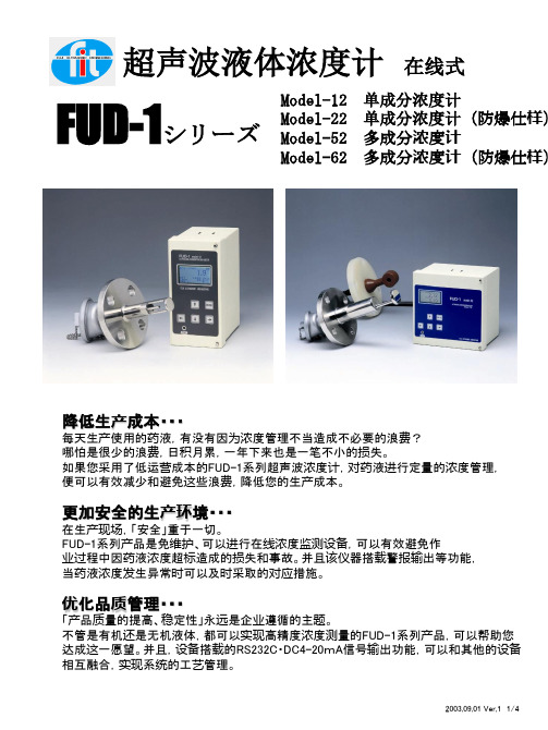
在线式
FUDFUD-1シリーズ
ModelModel-12 ModelModel-22 ModelModel-52 ModelModel-62
单成分浓度计 单成分浓度计(防爆仕样 单成分浓度计(防爆仕样) 多成分浓 多成分浓度计 多成分浓 防爆仕样 多成分浓度计(防爆仕样)
降低生产成本・・・ 降低生产成本・・・
优化品质管理・・・ 化品质管理・・・
「产品质量的提高、稳定性」永远是企业遵循的主题。 不管是有机还是无机液体,都可以实现高精度浓度测量的FUD-1系列产品,可以帮助您 达成这一愿望。并且,设备搭载的RS232C・DC4-20mA信号输出功能,可以和其他的设备 相互融合,实现系统的工艺管理。
2003.09.01 Ver.1 1/4
每天生产使用的药液,有没有因为浓度管理不当造成不必要的浪费? 哪怕是很少的浪费,日积月累,一年下来也是一笔不小的损失。 如果您采用了低运营成本的FUD-1系列超声波浓度计,对药液进行定量的浓度管理, 便可以有效减少和避免这些浪费,降低您的生产成本。
更加安全的生产环 更加安全的生产环境・・・ 产环境
在生产现场,「安全」重于一切。 FUD-1系列产品是免维护、可以进行在线浓度监测设备,可以有效避免作 业过程中因药液浓度超标造成的损失和事故。并且该仪器搭载警报输出等功能, 当药液浓度发生异常时可以及时采取的对应措施。
☆变换器安装位置灵活,安装后无需做繁琐的设置和调整。 ☆几乎不受测量对象噪音、振动、流速、颜色、污物等因素的影响 ☆仪器发信器输出功率小,不会对药液产生影响
维护方式简单, 方式简单 ■ 产品维护方式简单,运行成本低
☆产品耐腐蚀、耐久性优越,可以根据监测液体的对象选择合适的发信器材质 ☆没有必要对仪器做定期的な調整・校正 ☆产品结构简单,便于清洗维护。
检量 线
右图是体现音速、温度、浓度相关性的图 表(即检量线)。(右图以HaOH为例) 基于此特性制作的检量线被存储到数据元 件(DATA ROM)中。发信器检测到的音速 和温度信息通过该数据元件(DATA ROM)的 分析演算,得出液体具体的浓度值。 例如右图中:如果发信器检测到液体音速 值(纵轴)是2100m/sec,同时发信器内部的热 敏电阻检测到液体环境温度是60℃,根据检 量线可以得知液体浓度(横轴)是26.00wt%. FUD-1Model-12最多可以存储10组检量线 数据。
2003.09.01 Ver.1 3/4
超声波浓 超声波浓度计FUD-1系列 (多成分) 基本原理 FUD多成分)
在之前介绍的单成分浓度计基本原理的基础上,通过测量其他的物理量(电导率)实现3成 分中2种成分的浓度测量,对应机型为: FUD-1Model-52多成分浓度计。
如上图所示,超声波多成分浓度计要在单成分浓度计基本组成(变换器、浓度演算DATAROM、发信器 如上图所示,超声波多成分浓 要在单成分浓 基本组 变换器 度演算DATAROM、 DATAROM 线缆)的基础上添加电导 电导率 实现多成分的 多成分的测 及线缆)的基础上添加电导率计,实现多成分的测量。 超声波发信器和电导 计检出器线缆的 电导率 出器线缆 度均为10m,,因现场工况需要或者防爆仕 需要连 工况需要或者防爆仕样 超声波发信器和电导率计检出器线缆的标准长度均为10m,,因现场工况需要或者防爆仕样需要连接中 需要对线缆进行延长 对线缆进行延 装改动 不要随意改变 所示组合形式或切断线缆 线缆。 继器时,需要对线缆进行延长或组装改动,请不要随意改变上图所示组合形式或切断线缆。
检量 线
右图是体现音速、温度、浓度、电导率之 间相关性的图表(即检量线)。(右图以 HaOH和NaCL的混合液为例) 基于此特性制作的检量线被存储到数据元 件(DATA ROM)中。超声波发信器和电导 率计检测到的音速、温度和电导率信息通过 该数据元件(DATA ROM)进行分析演算,得 出2种液体各自具体的浓度值。 例如右图中:如果发信器检测到液体音速 值(纵轴)是1738m/sec,液体温度是94℃,电 导率计(纵轴)检测值为585mS/cm,根据检 量线可以得知HaOH浓度(横轴)是23.00wt%, NaCL的浓度是0.5wt% FUD-1Model-52最多可以存储7组检量线数 据。
2003.09.01 Ver.1 2/4
超声波液体浓度计FUD- 系列(单成分) 超声波液体浓度计FUD-1系列(单成分) FUD
基本原理
超声波在液体中的传播速度,根据液体的浓度及温度的不同会有相应的变化,根据这ห้องสมุดไป่ตู้特 性,该仪器可是根据所测液体的音速和温度的变化,实现高精度的浓度测量。 基于音速和温度的变化信息,记载在数据元件(DATA ROM)的检量线可以对药液的浓度 进行演算,得出浓度值。另外,药液的种类、测量范围等不同的情况下,可以通过增加存储 的检量线的方法实现多种类药液的多范围测量。
关于FUD-1系列 FUD■ 可以实时监测药液的浓度,可以简单地构置浓度管理系统。 。
☆可以搭载RS232C信息传输功能和输出4-20mA模拟信号 ☆具备计测的错误信号输出和报警输出功能 ☆具备自我诊断功能和错误信息显示功能 ☆作为备选功能,可以进行RS485信息输出和温度值输出
■简单的设置实现稳定的测量
2003.09.01 Ver.1 4/4
如上图所示:变换器、浓度演算元件DATAROM、 发信器及线缆是该仪器的基本组成。 如上图所示:变换器 度演算元件DATAROM、 信器及线缆是该仪器的基本组 DATAROM 线缆 器的基本 线缆的 准品为10m,,因现场工况需要或者防爆仕 需要连接中继 工况需要或者防爆仕样 需要对线缆进行延长 对线缆进行延 线缆的标准品为10m,,因现场工况需要或者防爆仕样需要连接中继器时,需要对线缆进行延长或组装 不要随意改变 所示组合形式或切断线缆 线缆。 改动,请不要随意改变上图所示组合形式或切断线缆。