catia管道布线
CATIA管路定制方法
管路定制方法一、安装为方便推广统一的标准件库和标准规范,在安装时建议用统一的安装目录,例如:catia的安装目录为D:\catiav5\,使安装后的目录是d:\catiav5\b08\intel_a\…。
环境文件目录设为d:\catiav5\env。
安装完后再新建目录d:\catiav5\catsetting和d:\catiav5\cattemp。
二、环境文件的定制1.执行开始-程序-catia-tools-environment editorv5r8,新建一个环境文件,执行菜单命令environment-new,mode应设置为global,product line设置为catia,选中add desktop icon。
2.编辑新建的文件d:\catiav5\env\equipment_sys.txt,修改内容如下:CATGraphicPath=d:\catiav5\b08\intel_a\resources\graphic;d:\catiav5\b08\intel_a\resources\graphic\icons;d:\catiav5\b08\intel_a\resources\graphic\figures;d:\catiav5\b08\intel_a\resources\graphic\splashscreens;d:\catiav5\b08\intel_a\resources\graphic\symbols;d:\catiav5\b08\intel_a\resources\graphic\textures;D:\_PROJECT\CATFCT(添加内容)CATUserSettingPath=D:\catiav5\CATSETTING(修改)CATTemp=D:\catiav5\CATTEMPCATDisciplinePath=D:\_PROJECT3.创建项目文件目录d:\ PROJECT,复制D:\catiav5\b08\intel_a\startup\EquipmentAndSystems下的子目录DiscreteValues、MigrationDirectory、Tubing,到d:\ PROJECT下面。
CATIA布线

CATIA三维布线
• 左图是一段局部线束。 • 绘制线束和绘制管路 一样,可以先绘制线 束中心的样条曲线。
CATIA三维布线
• 绘制曲线时,我们需 进入到曲线和曲面模 块,如左图
CATIA三维布线
• 进入模块后,介绍一 下右侧工具栏中需用 到的几个绘图工具。 • 1、点绘制工具 • 2、直线绘制工具 • 3、桥接工具
CATIA三维布线
• 关于点的捕捉,我们 常用到线条、圆心和 球心。 • 绘制直线时,我们通 常会用点与点、点和 方向的命令来绘制。
CATIA三维布线
• 接下来介绍桥接工具: 桥接是填补两线条之 间间隙的命令。操作 时需注意将方向选正 确。
CATIA三维布线
• 接下来
2024版CATIA教程

零件建模
掌握CATIA中零件建模的 基本方法,包括拉伸、旋 转、扫描和放样等。
2024/1/24
特征编辑
学习如何编辑零件的特征, 如倒角、圆角、抽壳和镜 像等。
参数化设计
了解参数化设计的概念, 并学习如何在CATIA中实 现参数化零件建模。
14
装配设计
装配体创建
学习如何在CATIA中创建新的装 配体,并掌握基本装配工具的使
2024/1/24
不断升级与发展
随着计算机技术的不断进步,CATIA也在不断升级和发展,逐渐从单一的CAD软件发展成为 一个集成化的PLM(产品生命周期管理)平台。
4
CATIA软件功能
三维建模
CATIA提供了一套完整的三维建模工具,支持参数化、特征 建模等多种建模方法,可快速创建复杂的三维模型。
工程分析
CATIA在机械制造领域也有广泛的应用,如 机床、模具、刀具等的设计和制造过程。
2024/1/24
6
PART 02
CATIA软件基本操作
REPORTING
2024/1/24
7
界面介绍
菜单栏
包含文件、编辑、视图、插入、 工具、窗口和帮助等菜单项, 用于执行各种命令。
特征树
显示当前文档中的特征结构和 层次关系,方便用户管理和编 辑特征。
2024/1/24
23
管路和布线设计
创建管路和布线
利用CATIA的管路和布线设计模块,创建复 杂的管路和布线系统。
管路和布线分析
检查管路和布线的走向、长度、直径等参数, 确保设计合理性。
2024/1/24
添加连接件和附件
为管路和布线系统添加连接件、阀门、开关 等附件。
CATIA汽车三维布线EHI讲解

4.创建线束
Multi-Branchable segment Bundle segment 单击 Multi-branchable Bundle Segment 命令 这时我们进入了electrical harness installation工作台
9
4.创建线束
点击命令后进入线束定义对话框
设定线束的直径,有 两种方式: 直径定义 截面积定义
2
课程目录
1. 介绍 EHI/EHA模块 2. electrical harness 的设置 3. 定义线束几何集 4. 创建线束 5. EHA模块详解
3
1.介绍 EHI/EHA模块
如何进入其工作界面?
Start -> Equipment & Systems menu-> Electrical Harness Assembly
依次选择线束的 控制元素及参考 元素
12
4.创建线束
添加和移除线 束分割点
定义线束的直 径和显示颜色 定义线束分割 点参考点位置
13
4.创建线束
添加线束分割点
移除线束分割点
确定分割点的 参考点。
可以通过长度和比 列两种方式确定分 割点得位置。
14
4.创建线束
移除线束
添加套筒
通过选择库文件中的套筒文件对线束进行套筒添加
创建一个geometrical bundle
1.创建一个 product 2.进入electrical harness assembly模块
3.点击geometrical bundle 定 义 product 为线束几何集 这时,product转换成 geometrical bundle 并具有特殊 的电器参数。
CATIA管路和电路完美设计
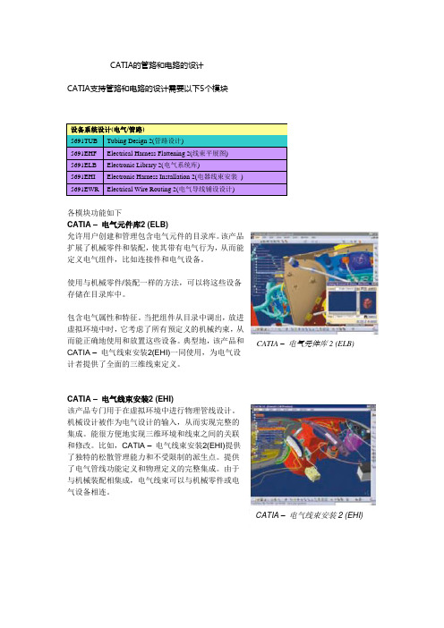
CATIA的管路和电路的设计CATIA支持管路和电路的设计需要以下5个模块设备系统设计(电气/管路)5691TUB Tubing Design 2(管路设计)5691EHF Electrical Harness Flattening 2(线束平展图)5691ELB Electronic Library 2(电气系统库)5691EHI Electronic Harness Installation 2(电器线束安装)5691EWR Electrical Wire Routing 2(电气导线铺设设计)各模块功能如下CATIA –电气元件库2 (ELB)允许用户创建和管理包含电气元件的目录库。
该产品扩展了机械零件和装配,使其带有电气行为,从而能定义电气组件,比如连接件和电气设备。
使用与机械零件/装配一样的方法,可以将这些设备存储在目录库中。
包含电气属性和特征。
当把组件从目录中调出,放进虚拟环境中时,它考虑了所有预定义的机械约束,从而能正确地使用和放置这些设备。
典型地,该产品和CATIA –电气元件库2 (ELB) CATIA –电气线束安装2(EHI)一同使用,为电气设计者提供了全面的三维线束定义。
CATIA –电气线束安装2 (EHI)该产品专门用于在虚拟环境中进行物理管线设计。
机械设计被作为电气设计的输入,从而实现完整的集成。
能很方便地实现三维环境和线束之间的关联和修改。
比如,CATIA –电气线束安装2(EHI)提供了独特的松散管理能力和不受限制的派生点。
提供了电气管线功能定义和物理定义的完整集成。
由于与机械装配相集成,电气线束可以与机械零件或电气设备相连。
CATIA –电气线束安装2 (EHI)CATIA – 电气导线布线2 (EWR)根据功能和配线规范,EWR 能在虚拟环境中创建电气导线。
根据外部电气CAD 系统或者CATIA – 电气功能定义(EFD)中定义的规范,进行导线布线。
可以在CATIA 电气线束安装2中设计的线束网络中;或是CATIA – 系统空间预留2(SSR)中定义的预留空间中,创建导线。
CATIA生产应用-管路开发教程
北京江达 版权所有
给定线路标识名称将会自动添加到 线路标识库中
选择设为缺省值可以基于基于预定 义的规则的属性自动命名
北京江达 版权所有
20
管路设计
管理管路线路标识 – 选择 (3/9)
选择一个线路标识
选择管线“ TL104-3/8in-SS150R-FG”
线路标识名称
公称尺寸
规格
过滤:在文档中 的线路标识
过滤列表
过滤:所有可用的线路标识
“ 管路功能”零件是被动的元素:管,螺母,弯头。它们在原理图上不可见。 “ 管路零件功能”零件是主动元素:阀,过滤器,支管。它们在原理图上可见。 设备是:泵,容器,执行器,等等。设备可能属于多专业。 ( 比如:泵可以是电力和液压链 连接的 ) 。需要使用设备布置工作台。 管嘴定义管路与设备的连接。 管线是一个基本的几何:
选择 确定 激活所选的项目和专业
ቤተ መጻሕፍቲ ባይዱ
北京江达 版权所有
18
管路设计
管理管路线路标识 (1/9)
要创建,传递,更名,合并或引入线路标识需要经过管理员授权
引入 合并 删除 更名 转换 创建 选择
北京江达 版权所有
19
管路设计
管理管路线路标识 – 创建 (2/9)
创建线路标识
在有些机构里面,线路是事先定义好的。 你可以创建你所需要的线路标识 你可以输入任意已知的属性,但是,公称尺寸和管路规范必须指定。
管路设计
用户界面:常用选项 (2/3)
北京江达 版权所有
13
管路设计
用户界面:通用环境图标
北京江达 版权所有
14
管路设计
用户界面:通用环境图标
北京江达 版权所有
CATIA管路详细设计
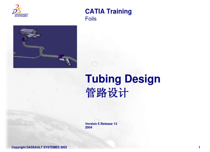
Foils
Tubing Design 管路设计
Version 5 Release 13 2004
Copyright DASSAULT SYSTEMES 2002
1
Course Presentation课程介绍
Objectives of the course目标
In this course you will learn how the CATIA Tubing Design product is used to quickly and efficiently create an intelligent tubing layout. 智能化管路设计
Table of Contents目录
1. Introduction to Tubing Design Fundamentals
Accessing the workbench模块介绍 User Interface: Tubing Design Icons界面介绍
2. Creating Line ID’s生成管线ID码 3. Routing a Run生成管线 4. Modifying a Run修改管线 5. Implementing Turn Rules管路拐弯 6. Placing Parts on a Run 管路定义功能 7. Generating Reports 生成管路拐点坐标
Rename ID重新命名ID
Copyright DASSAULT SYSTEMES 2002
5
User Interface: Tubing Design Icons (2/2)
Snap:
Snap Tool Options捕捉工具 To current Axis当前坐标轴
CATIA管道设计
CATIA管道设计在现代制造业中,CATIA是一种广泛应用的三维设计与工程软件。
它可以帮助工程师们进行精确的设计与模拟,并提高产品的设计质量和生产效率。
本文将主要讨论CATIA在管道设计方面的应用。
一、CATIA管道设计的重要性管道是许多工业设备和系统中不可或缺的组成部分,如电力站、化工厂、机械制造等。
合理的管道设计能够确保流体在系统中的稳定传输,提高能源的利用效率。
而CATIA作为一款功能强大的设计软件,可以提供全面的管道设计方案,包括管道的布局、支架设计、材料选择等,能够满足不同行业的需求。
二、CATIA管道设计的基本步骤1. 确定设计要求:在进行管道设计之前,需要明确设计的目标和要求,如流量要求、压力等级、环境条件等。
这些要求将决定整个设计过程中的参数选择。
2. 管道布局设计:根据设计要求和现场条件,使用CATIA进行管道布局设计。
可以通过CATIA的多种功能进行三维建模,包括创建管道、连接零件、确定管道的路径等。
3. 材料选择:根据设计要求和工作环境,选定适用的材料。
CATIA 可以提供材料库,方便用户进行材料的选择和比较。
4. 管道支架设计:管道设计过程中,需要考虑管道的支撑和固定。
使用CATIA的支架设计功能,可以快速设计出稳固的管道支架,并进行强度分析。
5. 模拟和分析:在设计完成后,可以使用CATIA进行流体模拟和强度分析,以确保管道在各种工况下的稳定性和安全性。
三、CATIA管道设计的优势1. 高效节省时间:CATIA可以帮助工程师们快速创建三维模型,并进行各种分析和模拟,大大缩短设计周期,提高工作效率。
2. 准确性和精度:CATIA提供了丰富的功能和工具,可以精确地进行管道的设计和分析,保证设计结果的准确性和精度。
3. 可视化演示:CATIA具备良好的可视化演示功能,可以将设计结果以三维模型或动画的形式展示出来,方便工程师们进行沟通和评审。
4. 兼容性强:CATIA具有广泛的兼容性,可以与其他软件进行数据交换,方便与其他系统的协同工作。
- 1、下载文档前请自行甄别文档内容的完整性,平台不提供额外的编辑、内容补充、找答案等附加服务。
- 2、"仅部分预览"的文档,不可在线预览部分如存在完整性等问题,可反馈申请退款(可完整预览的文档不适用该条件!)。
- 3、如文档侵犯您的权益,请联系客服反馈,我们会尽快为您处理(人工客服工作时间:9:00-18:30)。
Electrical Harness Installation 电气安装Electrical HarnessAssembly电气装配Getting Started Samples简例CATIA TrainingFoilsElectrical Harness Installation电气安装Electrical Harness Assembly电气装配Version 5 Release 132004Course PresentationObjectives of the courseIn this course you will learn how to build a harness integrated within the DMU and how to connect the bundle segments to your electrical components.下面的讲义介绍如何在电子装配中建立电气用具和如何使用线束连接它们Targeted audienceNew Electrical V5 users适用对象是CATIA V5初级学者Prerequisites0.5 dayCatalog Editor, CATIA V5 basicsTable of Contents内容提要1.Introduction to Electrical Harness Installation介绍Electrical Harness Installation workbench presentation电气安装模块菜单位置2.Bundle Segment (BNS) definition线束定义Geometric Bundle几何定义Bundle Segments线束定义Split a Bundle Segment线束分段3.Links Management线束联结Link the electrical objects与电器器件的联结Links Management联结修改4.Local Slack Management线束局部松弛度的修改Adding Local Slack增加Removing Local Slack取消5.Support Management线束支撑Routing of BNS through Supports增加Removal of Support from Bundle Segment取消6.Rectangular Sections矩形截面Change bundle segment section改变线束截面7.Floating Junction线束连接点Define the constraints of the floating junction定义连接点Accessing the workbenches进入电气安装界面Allows the geometrical harnesses creation. Itlinks bundle segments together to create thisharness.产生线束定义,线束连接Allows the bundle segmentscreation within a geometricalbundle线束的几何定义User Interface 用户界面Electrical HarnessAssembly电气装配Electrical HarnessInstallation电气安装线束几何定义Terminology术语Geometric Bundle线束组Electrical object federating a bundle segments group.A geometrical bundle is mandatory in order to create a bundle segment.Bundle Segment线束Also called segment, a geometrical subdivision of a geometrical bundle.It is the branch of harness graphical representation in the digital mock-up.Support电器库元件支承件An Electrical catalog item that is utilized when routing geometrical bundles.It controls the entry and exit of the bundle segment as it is routed through the DMU.Floating Junction线束连接点A junction that automatically finds a natural position.Alternative Bundle Segment Section线束截面The sections of a bundle segment need not be circular, they can follow the profile of another sketch.Define a geometric bundle定义线束组Select the “Bundle Segment” function1The new point is added to the BNSSelect the pointfunction and give the coordinates2选择图标生成点的图标Select the “Bundle Segment” function1The new line is added to the BNSSelect the line function give it the coordinates2选择图标生成线的图标Define a plane 生成平面Select the “Bundle Segment” function1The plane is added to the bundle segmentSelect the “Plane” function and define its coordinates2选择图标生成平面的图标Define a bundle segment 定义单个线束The BNS is updatedSelect the “Bundle Segment Definition” function and define it2Select the “Bundle Segment” function1选择图标生成线束的图标Define a bundle segment定义线束段123截面和松弛度设置线束控制点生成样条线123Select the points the BNS has to go through and the surface.You may have to invert the BNS orientation in case the surface orientation is not correspondingIf two BNS are on two distinct surfaces, you have to connect them with a third BNS not lying on any surface or create a join.选曲面线束两端点在此曲面上改方向连接两个不同面上的线束The external references to thepoints the BNS is using arecreated automatically.The surface the BNS is lying on isrepresented by an externalreference as well.Tools / Options / Mechanical Design / Part Design / General / External References : Keep Link with Selected Object.Activate this option or you will loose the links to the objects that belong to other parts.相关设置自动生成相关参考点和曲面Split a bundle segment (1/2)分割线束Create a new point onthe Bundle Segmentspline (“on curve”)2Select the “BundleSegment” function1Isolate point3选图标生成点隔离点Split a bundle segment (2/2)The BNS is split.5Exit the Bundle Segment command4Add point to the BNS route definition6Split the bundle segment加入点退出分割线束分割完毕Links Management线束连接Objective : You are going to learn how to connect two bundle segments together or to an electrical componentLink the electrical objects线束和电器连接Links management连接管理Between two bundle segments 两线束之间连接Create two bundlesegments1Select the “Link” functionand both BNS, close to theextremity to link2The GBN is updated生成两线束选择图标和两线束连接Between a bundle segment and an electrical component 线束和电器连接Create an equipment and a BNS within a GBN12Select the function “Link”, the BNS and a connectorThe BNS got himself connected to theconnector automatically产生设备和线束选择LINK 图标线束和电器自动连接Links Visualization连接图示“相关目标”图标Select the “RelatedObjects” functionUnlink two electrical objects切断连接Select the funtion“Unlink”12The connection islost but thegeometry remains.切断图标连接去掉,线束还在Local Slack Management松弛度Objective : You are going to learn how to add or remove Slack locally along the bundle segmentAdd Local Slack增加Remove Local Slack去掉Add Local Slack to a bundle segmentSelect the “Add local slack to a bundle segment portion1Select the bundle segment next to the point where the additional slack is to start. Click on “Add slack” , key Slack Definition value.2Slack is added to the bundle segment 图标在线束上欲增加松弛度附近选点输入松弛度松弛加在选点之后的线束Removing Local Slack from a bundle segment 去掉松弛Select the “Add local slack to a bundle segment portion1Select the bundle segment to display the Local SlackManagement Panel. Click on “Ignore Slack”2Slack is Ignored and the bundle is modified同样图标不同选项取消松弛Support Management增加线束支撑Objective : You are going to learn how to add a Support to a bundle segment and also how to remove a Support from a bundle segmentAdd Support增加Remove Support去掉Add a support to a bundle segmentCreate a bundle segmentrouted through 3 supports.Add an additional support.1Select the “Add Support tobundle segment” andselect the bundle segmentfollowed by the Support2The bundle is routedThrough the support 三支撑模型,支撑必须用Electrical Part Design中Support 命令定义选图标和第四支撑增加完毕Remove a support去掉支撑1Select the “RemoveSupport from bundlesegment” and select thebundle segment2The Support is removed and the bundle route is modified图标Section Management线束截面Objective : You are going to learn how to change the section of a bundle segment from circular to rectangular.Change Section更换截面Replacing a circular section with a rectangular sectionCreate a bundle segment1Sketch new rectangular profile on the same plane as the current bundle segment profile2Activate the “Rib Definition” panel and select the rectangular profile3产生一个线束增加截面草图更换截面Floating Junction线束连接点Objective : You are going to learn how to manage a floating bundle segment junctionManage bundle segment Junction positioning修改连接点位置Floating Junction ManagementDefine the constraint geometryfor the floating junction1Create the bundle segments2Move the Junction 增加分支点去掉分支点Electrical Harness Flatterning线束展平Electrical Harness Flattening offers the following main functions:•it flattens bundle segments or electrical and geometrical bundles •展平线束•it straightens bundle segments•拉直线束•it rotates whole bundle segments or bend them at a defined point •旋转和弯曲线束•it rolls bundle segments•卷线束•it scales bundle segments by introducing fake lengths•线束变比例•it can be updated at any time during your session thanks to the synchronization option 与实体关联和更新•it allows you to choose the type of representation of your drawing •选择平面图的类型•it allows you to annotate the wires of your drawing.•平面图标注Getting Started Samples起始简例Electrical Harness Flatterning线束展平Defining Harness Flattening Parameters定义展平参数Extracting 3D Data输入三维线束Flattening Harness线束展平Straightening Bundle Segments线束拉直Rotating Bundle Segments线束旋转Rolling Bundle Segments线束卷Scaling Bundle Segments线束变比例Synchronizing the Environment根据三维更新Filtering Wires Based on ExternalConfiguration System线束过滤External Data Access获取外部数据Related Objects相关目标。