英文翻译原文
中英文翻译英文原文
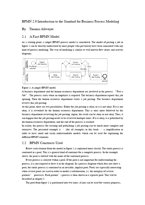
BPMN 2.0 Introduction to the Standard for Business Process Modeling By Thomas Allweyer2.1 A First BPMN ModelAs a starting point, a simple BPMN process model is considered. The model of posting a job in figure 1 can be directly understood by most people who previously have been concerned with any kind of process modeling. The way of modeling is similar to well known flow charts and activity diagrams.Figure 1: A simple BPMN modelA business department and the human resources department are involved in the process “Post a Job”. The process starts when an employee is required. The business department reports this job opening. Then the human resources department writes a job posting. The business department reviews this job posting.At this point, there are two possibilities: Either the job posting is okay, or it is not okay. If it is not okay, it is reworked by the human resources department. This is once more followed by the business department reviewing the job posting. Again, the result can be okay or not okay. Thus, it can happen that the job posting needs to be reviewed multiple times. If it is okay, it is published by the human resources department, and the end of the process is reached.In reality, the process for creating and publishing a job posting can be much more complex and extensive. The presented example is –like all examples in this book –a simplification in order to have small and easily understandable models which can be used for explaining the different BPMN elements.2.2 BPMN Constructs UsedBelow each element from the model in figure 1 is explained more closely. The entire process is contained in a pool. This is a general kind of container for a complete process. In the example above, the pool is labeled with the name of the contained process.Every process is situated within a pool. If the pool is not important for understanding the process, it is not required to draw it in the diagram. In a process diagram which does not show a pool, the entire process is contained in an invisible, implicit pool. Pools are especially interesting when several pools are used in order to model a collaboration, i.e. the interplay of several partners’processes. Each partner’s process is then shown in a separate pool. This will be described in chapter 5.The pool from figure 1 is partitioned into two lanes. A lane can be used for various purposes,e.g. for assigning organizational units, as in the example, or for representing different components within a technical system. In the example, the lanes show witch of the process’s activities are performed by the business department and which by the human resource department.Pools and lanes are also called “swimlanes”. They resemble the partitioning of swimming pools into lanes. Every participant of a competition swims only in his own lane.The process itself begins with the start event “Employee required”. Processes usually have such a start event. Its symbol is a simple circle. In most cases it makes sense to use only one start event, not several ones.A rounded rectangle represents an activity. In an activity something gets done. This is expressed by the activities’names, such as “Report Job Opening”or “Review Job Posting”.The connecting arrows are used for modeling the sequence flow. They represent the sequence in which the different events, activities, and further elements are traversed. Often this is called control flow, but in BPMN there is a second type of flow, the message flow, which influences the control of a process as well, and is therefore some kind of control flow, too. For that reason, the term “sequence flow”is used. For distinguishing it from other kinds of flow, it is important to draw sequence flows with solid lines and filled arrowheads.The process “Post a Job”contains a split: The activity “Review job posting”is followed by a gateway. A blank diamond shape stands for an exclusive gateway. This means that out of several outgoing sequence flows, exactly one must be selected. Every time the right gateway in the job posting-process is reached, a decision must be taken. Either the sequence flow to the right is followed, leading to the activity “Publish Job Posting”, or the one to the left is selected, triggering the activity “Rework Job Posting”. It is not possible to follow both paths simultaneously.The logic of such a decision is also called “exclusive OR”, abbreviated “XOR”. The conditions on the outgoing paths determine which path is selected. If a modeling tool is used and the process has to be executed or simulated by a software program, then it is usually possible to formally define exact conditions. Such formal descriptions, which may be expressed in a programming language, can be stored in special attributes of the sequence flows.If, on the other hand, the purpose of a model is to explain a process to other people,then it is advisable to write informal, but understandable, statements directly into the diagram, next to the sequence flows. The meaning of “okay”and “not okay”after the activity called “Review Job Posting”is clear to humans –a program could not make use of it.Gateways are also used for merging alternative paths. In the sample process, the gateway on the left of the activity “Review Job Posting”merges the two incoming sequence flows. Again, this is an exclusive gateway. It expects that either the activity“Write Job Posting”or “Rework Job Posting”is carried out before the gateway is reached –but not both at the same time. It should be taken care to use a gateway either for splitting or for joining, but not for a combination of both. The last element in the example process is the end event. Like the start event it has a circle as symbol –but with a thick border.2.3 Sequence Flow LogicThe flow logic of the job posting process above is rather easy to understand. In more complex models it is sometimes not clear how the modeled structure exactly is to be interpreted. Therefore it is helpful if the meaning of the sequence flow’s elements is defined in an unambiguous way.The logic of a process diagram’s sequence flow can be explained by “tokens”. Just as in a board game tokens are moved over the board according to the game’s rules, one can imagine moving tokens through a process model according to BPMN’s rules.Every time the process is started, the start event creates a token (cf. figure 2). Since the job posting process is carried out more than once, many tokens can be created in the course of time. Thereby it can happen that the process for one job posting is not yet finished, when the process for posting another job starts. As it moves through the process, each token is independent from the other tokens’movements.Figure 2: A start event creates a tokenThe token that has been created by the start event moves through the sequence flow to the first activity. This activity receives a token, performs its task (in this case it reports a job opening), and then releases it to the outgoing sequence flow (cf. figure 3).Figure 3: An activity receives a token and forwards it after completionThe following activity forwards the token. It then arrives at the merging exclusive gateway. The task of this gateway is simple: It just takes a token that arrives via any incoming sequence flow and moves it to the outgoing sequence flow. This is shown in figure 4. In case A, a token arrives from the left, in case B from below. In both cases the token is routed to the outgoing sequence flow to the right.Figure 4: Routing of a token by a merging exclusive gatewayThe task of the splitting exclusive gateway is more interesting. It takes one arriving token and decides according to the conditions, to which sequence flow it should be moved. In case A in figure 5, the condition “okay”is true, i.e. the preceding review activity has produced a positive result. In this case, the token is moved to the right. Otherwise, if the condition “not okay”is true, the token is moved to the downwards sequence flow (case B).The modeler must define the conditions in such a way that always exactly one of the conditions is true. The BPMN specification does not state how to define conditions and how to check whichconditions are true. Since the considered process is not executed by software, the rather simple statements used here are sufficient. Otherwise, it would be necessary to define the conditions according to the requirements and rules of the software tool.The token may travel several times through the loop for reworking the job posting. Finally it arrives at the end event. This simply removes any arriving token and thus finishes the entire process (figure 6).Figure 5: Routing of a token by a splitting exclusive gatewayThe sequence flow of every process diagram can be simulated in this way with the help of tokens. This allows for analyzing whether the flow logic of a process has been modeled correctly.It should be noted that a token does not represent such a thing as a data object or a document. In the case of the job posting process, it could be imagined to have a document “job posting”flowing through the process. This document could contain all required data, such as the result of the activity “Review Job Posting”. At the splitting gateway, the decision could then be based on this attribute value. However, the BPMN sequence flow is constrained to the pure order of execution. The tokens therefore do not carry any information, other than a unique identifier for distinguishing the tokens from each other. For data objects there are separate BPMN constructs which will be presented in chapter 10.2.4 Presentation OptionsUsually pools are drawn horizontally. The preferred direction of sequence flow is then from left to right. On the other hand, it is also possible to use vertical pools and to draw the sequence flow from top to bottom, as in the example in figure 7.It makes sense to decide for only one of these possibilities –horizontal or vertical. Nevertheless there are modeling tools which only support horizontal modelingFigure 6: An end event removes an arriving tokenFigure 7: Vertical swimlanes and nested lanesFigure 7 also shows an example of nested lanes. The lane labeled “Sales”is partitioned into the two lanes “Sales Force”and “Order Processing”. In principle it is possible to partition these lanes again, etc., although this only makes sense up to a certain level of depth.It is not prescribed where to place the names of pools and lanes. Typical are the variants selected for figure 1 and figure 7. Here the names are placed on the left of the pools or lanes, or at the top for the vertical style, respectively. The name of a pool is separated by a line. The names of the lanes, however, are placed directly within the lanes. A separation line is only used for a lane that is partitioned into further sub-lanes. Lanes can also be arranged as a matrix. The procurement process in figure 8 runs through a business department and the procurement department, both of which span a branch office and the headquarters. When a demand occurs in a branch’s business department, this department reports the demand. In the next step, the procurement is approved by the same department in the headquarters. The central part of the procurement department then closes a contract with a supplier, followed by the branch’s purchasing department carrying out the purchase locally.Although the BPMN specification explicitly describes the possibility of such a matrix presentation, it is hardly ever applied, so far.12.2 Message CorrelationThe contents of the message flows within one conversation are always related to each other. For example, all messages that are exchanged within one instance of the conversation “Process Order for Advertisement”relate to the same advertisement order. It is therefore possible to use the order ID for the correlation, i.e. the assignment of messages to a process instance. If a customer receives an advertisement for approval, he can determine the corresponding order –and thus the process instance –based on the order ID. All messages of a conversation have a common correlation.A simple conversation which is not broken down into other conversations is called communication. Therefore, the lines are called communication links (the specification draft at some places alsocalls them conversation links). A conversation has always communication links to two or more participants.If the end of a communication link is forked, multiple partners of the same type can be part of the communication, otherwise exactly one. “Process Order for Advertisement”has exactly one customer and one advertising agency as participants, but multiple designers. Therefore, the designer’s pool contains a multiple marker. However, having only the multiple marker in the pool is not sufficient. The conversation “Handle order for an illustration”, for example, has only one designer as participant. Therefore, the respective end of the communication link is not forked.12.3 Hierarchies of ConversationsBesides communications, it is also possible to use sub-conversations. Similar to sub-processes they are marked with a ‘+’-sign. The details of a sub-conversation can be described in another conversation diagram. The diagram of a sub-conversation can only contain those participants who are linked to the sub-conversation within the parent diagram.Figure 171 shows the detailed conversation diagram for the sub-conversation “Process Order for Advertisement”As can be seen from this diagram, it is also possible to draw message flows directly into the conversation diagram. Other than collaboration diagrams, conversation diagrams are not allowed to show processes in the pools or choreographies between the pools.Figure 171: Conversation diagram for sub-conversation “Process Order for Advertisement”The diagram contains those message flows that are related to the same order. To be more precise, they relate to the same inquiry. At the beginning, an order has not been placed yet, and not every inquiry turns into an order. Therefore, the common reference point is the inquiry.Besides the explicitly displayed message flows between customer and advertising agency, the diagram also contains the communication “Assignment of Graphics Design”. All message flows of this communication are also related to the same inquiry, but this information is not sufficient for the advertising agency in order to assign all incoming messages correctly. This is due to the fact that availability requests are sent to several designers. The advertising agency has to correctly assign each incoming availability notice to the correct availability request. Thus, additional information is required for correlating these messages, e.g. the IDs of the availability requests.Therefore it is possible to define a separate communication for the message flows between advertising agency and designer. The message exchanges of this communication can also be modeled in a collaboration diagram (figure 172) or in a choreography diagram (figure 173). Of course, it is also possible to show the message flows of the entire sub-conversation within a single diagram (figures 161 and 162 in the previous chapter).Figure 172: Collaboration diagram for communication “Assignment of Graphics Design”Like sub-processes, sub-conversations can also be expanded, i.e. the hexagon is enlarged, and the detailed conversation is shown in its interior. However, it is graphically not easy to include, for example, the contents of figure 171 into an expanded sub-conversation in figure 170. Unfortunately, the BPMN specification draft does not contain any examples for expandedsub-conversations either.。
牛津英语必修一课文原文及中文翻译

M1U1S C H O O L l i f e i n t h e U KGoing to a British high school for one year was a very enjoyable and exciting experience for me. I was very happy with the school hours in Britain because school starts around 9 a later than usual as schools in China begin before 8 a.m.On the first day, all of the new students attended an assembly in the school hall. I sat next to a girl whose name is Diane. We soon became best friends. During the assembly, the headmaster told us about the rules of the school. He also told us that the best way to earn respect was to devote oneself to study and achieve high grades. This sounded like my school in China.I had many teachers in the past year. Mr. Heywood , my class teacher, was very helpful. My favorite teacher was Miss Burke—I loved the lessons that she gave in English Literature. In our class there were 28 students. This is about the average size for British schools. We had to move to different classrooms for different classes. We also had different students in some classes, so it was a struggle for me to remember all the faces and names.I found the homework was not as heavy as what I used to get in my old school, but it was a bit challenging for me at firs t because all the homework was in English. I felt lucky as all my teachers gave me much encouragement and I enjoyed all my subjects: English, History, English Literature, Computer Science, Maths, Science, PE, Art, Cooking and French.My English improved a lot as I used English every day and spent an hour each day reading English books in the library.I usually went to the Computer Club during the lunch break, so I could send e-mails to my family and friends back home for free. I also had an extra French class on Tuesday evenings. Cooking was really fun as I learned how to buy, prepare and cook food. At the end of term we held a class party and we all had to cook something. I was glad that all my classmates were fond of the cake that I made.Students at that school have to study Maths, English and Science, but can stop studying some subjects if they don’t like them, for example, History and French. They can choose other subjects like Art and Computer Science or Languages such as Spanish and German. In the Art class that I took, I made a small sculpture. Though it didn’t look very beautiful when it was finished, I still liked it very much.I missed Chinese food a lot at lunch. British food is very different. British people like eating dessert at the end of their main meal. After lunch, we usually played on the school field. Sometimes I played football with the boys. Sometimes I just relaxed under a tree or sat on the grass.I was very lucky to experience this different way of life. I look back on my time in the UK with satisfaction, and I really hope to go back and study in Manchester again.在英国的学校生活在英国上了一年的中学对我来说是一段非常令人愉快和兴奋的经历。
英文原文加中文翻译
英文原文:Rehabilitation of rectangular simply supported RC beams with shear deficienciesusing CFRP compositesAhmed Khalifa a,* , Antonio Nanni ba Department of Structural Engineering, University of Alexandria, Alexandria 21544, Egyptb Department of Civil Engineering, University of Missouri at Rolla, Rolla, MO 65409, USAReceived 28 April 1999; received in revised form 30 October 2001; accepted 10 January 2002AbstractThe present study examines the shear performance and modes of failure of rectangular simply supported reinforced concrete(RC) beams designed with shear deficiencies. These members were strengthened with externally bonded carbon fiber reinforced polymer (CFRP) sheets and evaluated in the laboratory. The experimental program consisted of twelve full-scale RC beams tested to fail in shear. The variables investigated within this program included steel stirrups, and the shear span-to-effective depth ratio, as well as amount and distribution of CFRP. The experimental results indicated that the contribution of externally bonded CFRP to the shear capacity was significant. The shear capacity was also shown to be dependent upon the variables investigated. Test results were used to validate a shear design approach, which showed conservative and acceptable predictions.○C2002 Elsevier Science Ltd. All rights reserved.Keywords: Rehabilitation; Shear; Carbon fiber reinforced polymer1. IntroductionFiber reinforced polymer (FRP) composite systems, composed of fibers embedded in a polymeric matrix, can be used for shear strengthening of reinforced con-crete (RC) members [1–7]. Many existing RC beams are deficient and in need of strengthening. The shear failure of an RC beam is clearly different from its flexural failure. In shear, the beam fails suddenly without sufficient warning and diagonal shear cracks are consid-erably wider than the flexural cracks [8].The objectives of this program were to:1. Investigate performance and mode of failure of simply supported rectangular RC beams with shear deficien-cies after strengthening with externally bonded CFRP sheets.2. Address the factors that influence shear capacity of strengthened beams such as: steel stirrups, shear span-to-effective depth ratio (a/d ratio), and amount and distribution of CFRP.3. Increase the experimental database on shear strength-ening with externally bonded FRP reinforcement.4. Validate the design approach previously proposed by the authors [9].For these objectives, 12 full-scale, RC beams designed to fail in shear were strengthened with different CFRP schemes. These members were tested as simple beams using a four-point loading configuration with two different a/d ratios.2. Experimental program2.1. Test specimens and materialsTwelve full-scale beam specimens with a total span of 3050 mm. and a rectangular cross-section of 150-mm-wide and 305-mm-deep were tested. The specimens were grouped into two main series designated SW and SO depending on the presence of steel stirrups in the shear span of interest.Series SW consisted of four specimens. The details and dimensions of the specimens designated series SW are illustrated in Fig. 1a. In this series, four 32-mm steel bars were used as longitudinal reinforcement with two at top and two at bottom face of the cross-section to induce a shear failure. The specimens were reinforced with 10-mm steel stirrups throughout their entire span. The stirrups spacing in the shear span of interest, right half, was selected to allow failure in that span.Series SO consisted of eight beam specimens, which had the same cross-section dimension and longitudinal steel reinforcement as for series SW. No stirrups were provided in the test half span as illustrated in Fig. 1b.Each main series (i.e. series SW and SO) was subdivided into two subgroups according to shear span-to-effective depth ratio. This was selected to be a/d = 3 and 4, resulting in the following four subgroups: SW3;SW4; SO3; and SO4.The mechanical properties of the materials used for manufacturing the test specimens are listed in Table 1.Fabrication of the specimens including surface preparation and CFRP installation is described elsewhere [10].Table 12.2. Strengthening schemesOne specimen from each series (SW3-1, SW4-1, SO3-1 and SO4-1) was left without strengthening as a control specimen, whereas eight beam specimens were strengthened with externally bonded CFRP sheets following three different schemes as illustrated in Fig. 2.In series SW3, specimen SW3-2 was strengthened with two CFRP plies having perpendicular fiber directions (90°/0°). The first ply was attached in the form of continuous U-wrap with the fiber direction oriented perpendicular to the longitudinal axis of the specimen (90°). The second ply was bonded on the two sides of the specimen with the fiber direction parallel to the beam axis(0°).This ply [i.e. 0°ply] was selected to investigate the impact of additional horizontal restraint on shear strength.In series SW4, specimen SW4-2 was strengthened with two CFRP plies having perpendicular fiber direction (90°/0°) as for specimen SW3-2.Four beam specimens were strengthened in series SO3. Specimen SO3-2 was strengthened with one-ply CFRP strips in the form of U-wrap with 90°-fiber orientation. The strip width was 50 mm with center-to-center spacing of 125 mm. Specimen SO3-3 was strengthened in a manner similar to that of specimen SO3-2, butwith strip width equal to 75 mm. Specimen SO3-4 was strengthened with one-ply continuous U-wrap (90°). Specimen SO3-5 was strengthened with twoCFRP plies (90°/0°) similar to specimens SW3-2 and SW4-2.In series SO4, two beam specimens were strengthened. Specimen SO4-2 was strengthened with one-ply CFRP strips in the form of U-wrap similar to specimen SO3-2. Specimen SO4-3 was strengthened with one-ply continuous U-wrap (90°) similar to SO3-4.2.3. Test set-up and instrumentationAll specimens were tested as simple span beams subjected to a four-point load as illustrated in Fig. 3. A universal testing machine with 1800 KN capacity was used in order to apply a concentrated load on a steel distribution beam used to generate the two concentrated loads. The load was applied progressively in cycles, usually one cycle before cracking followed by three cycles with the last one up to ultimate. The applied load vs. deflection curves shown in this paper are the envelopes of these load cycles.Four linear variable differential transformers (LVDTs) were used for each test to monitor vertical displacements at various locations as shown in Fig. 3. Two LVDTs were located at mid-span on each side of the specimen. The other two were located at the specimen supports to record support settlement.For each specimen of series SW, six strain gauges were attached to three stirrups to monitor the stirrup strain during loading as illustrated in Fig. 1a. Three strain gauges were attached directly to the FRP sheet on the sides of each strengthened beam to monitor strain variation in the FRP. The strain gauges were oriented in the vertical direction and located at the section mid-height with distances of 175, 300 and 425 mm, respectively, from the support for series SW3 and SO3. For beam specimens of series SW4 and SO4, the strain gauges were located at distance of 375, 500 and 625 mm, respectively, from the support.3. Results and discussionIn the following discussion, reference is always made to weak shear span or span of interest.3.1. Series SW3Shear cracks in the control specimen SW3-1 were observed close to the middle of the shear span when the load reached approximately 90 kN. As the load increased, additional shear cracks formed throughout, widening and propagating up to final failure at a load of 253 kN (see Fig. 4a).In specimen SW3-2 strengthened with CFRP (90°/0°), no cracks were visible on the sides or bottom of the test specimen due to the FRP wrapping. However,a longitudinal splitting crack initiated on the top surface of the beam at a high load of approximately 320 kN.The crack initiated at the location of applied load and extended towards the support. The specimen failed by concrete splitting (see Fig. 4b) at total load of 354 kN. This was an increase of 40% in ultimate capacity compared to the control specimen SW3-1. The splitting failure was due to the relatively high longitudinal compressive stress developed at top of the specimen, which created a transverse tension, led to the splitting failure. In addition, the relatively large amount of longitudinal steel reinforcement combined with over-strengthening for shear by CFRP wrap probably caused this mode of failure. The load vs. mid-span deflection curves for specimens SW3-1 and SW3-2 are illustrated in Fig. 5, to show the additional capacity gained by CFRP.The maximum CFRP vertical strain measured at failure in specimen SW3-2 was approximately 0.0023 mm/mm, which corresponded to 14% of the reported CFRP ultimate strain. This value is not an absolute because it greatly depends on the location of the strain gauges with respect to a crack. However, the recorded strain indicates that if the splitting did not occur, the shear capacity could have reached higher load.Comparison between measured local stirrup strains in specimens SW3-1 and SW3-2 are shown in Fig. 6. The stirrups 1, 2 and 3 were located at distance of 175, 300 and 425 mm from the support, respectively. The results showed that the stirrups 2 and 3 did not yield at ultimate for both specimens. The strains (and the forces) in the stirrups of specimen SW3-2 were, in general, smaller than those of specimen SW3-1 at the same level of loading due to the effect of CFRP.Fig. 6. Applied load vs. strain in the stirrups for specimens SW3-1 and SW3-2. 3.2. Series SW4In specimen SW4-1, the first diagonal crack was formed in the member at a totalapplied load of 75 kN. As the load increased, additional shear cracks appeared throughout the shear span. Failure of the beam occurred when the total applied load reached 200 kN. This was a decrease of 20% in shear capacity compared to the specimen SW3-1 with a/d ratio=3.In specimen SW4-2, the failure was controlled by concrete splitting similar to test specimen SW3-2. The total applied load at ultimate was 361 kN with an 80% increase in shear capacity compared to the control specimen SW4-1. In addition, the measured strains in the stirrups for specimen SW4-2 were less than those of specimen SW4-1. The applied load vs. mid-span deflection curves for beams SW4-1 and SW4-2 are illustrated in Fig. 7. It may be noted that specimen SW4-2 resulted in greater deflection when compared to specimen SW4-1.When comparing the test results of series SW3 specimens to that of series SW4, the ultimate failure load of specimen SW3-2 and SW4-2 was almost the same. However, the enhanced capacity of specimen SW3-2 (a/d=3) due to the addition of the CFRP reinforcement was 101 kN, while specimen SW4-2 (a/d=4) was 161 kN. This indicates that the contribution of external CFRP reinforcement may be influenced by the ayd ratio and appears to decrease with a decreasing a/d ratio. Further, for both strengthened specimens (SW3-2 and SW4-2), CFRP sheets did not fracture or debond from the concrete surface at ultimate and this indicates that CFRP could provide additional strength if the beams did not failed by splitting.3.3. Series SO3Fig. 8 illustrates the failure modes for series SO3 specimens. Fig. 9 details the applied load vs. mid-span deflection for the specimens.The failure mode of control specimen SO3-1 was shear compression. Failure of the specimen occurred at a total applied load of 154 kN. This load was a decrease of shear capacity by 54.5 kN compared to the specimen SW3-1 due to the absent of the steel stirrups. In addition, the crack pattern in specimen SW3-1 was different from of specimen SO3-1. In specimen SW3-1, the presence of stirrups provided a better distribution of diagonal cracks throughout the shear span.In specimen SO3-2, strengthened with 50-mm CFRP strips spaced at 125 mm, the first diagonal shear crack was observed at an applied load of 100 kN. The crackpropagated as the load increased in a similar manner to that of specimen SO3-1. Sudden failure occurred due to debonding of the CFRP strips over the diagonal shear crack, with spalled concrete attached to the CFRP strips. The total ultimate load was 262 kN with a 70% increase in shear capacity over the control specimen SO3-1. The maximum local CFRP vertical strain measured at failure in specimen SO3-2 was 0.0047 mm/mm (i.e. 28% of the ultimate strain), which indicated that the CFRP did not reach its ultimate.Specimen SO3-3, strengthened with 75-mm CFRP strips failed as a result of CFRP debonding at a total applied load of 266 kN. No significant increase in shear capacity was noted compared to specimen SO3-2. The maximum-recorded vertical CFRP strain at failure was 0.0052 mmymm (i.e. 31% of the ultimate strain).Specimen SO3-4, which was strengthened with a continuous CFRP U-wrap (908), failed as a result of CFRP debonding at an applied load of 289 kN. Results show that specimen SO3-4 exhibited increase in shear capacity of 87, 10 and 8.5% over specimens SO3-1,SO3-2 and SO3-3, respectively. Applied load vs. vertical CFRP strain for specimen SO3-4 is illustrated in Fig. 10 in which strain gauges sg1, sg2 and sg3 were located at mid-height with distances of 175, 300 and 425 mm from the support, respectively. Fig.10 shows that the CFRP strain was zero prior to diagonal crack formation, then increased slowly until the specimen reached a load in the neighborhood of the ultimate strength of the control specimen. At this point, the CFRP strain increased significantly until failure. The maximum local CFRP vertical strain measured at failure was approxi- mately 0.0045 mm/mm.When comparing the results of beams SO3-4 and SO3-2, the CFRP amount used to strengthen specimen SO3-4 was 250% of that used for specimen SO3-2. Only a 10% increase in shear capacity was achieved for the additional amount of CFRP used. This means that if an end anchor to control FRP debonding is not used, there is an optimum FRP quantity, beyond which the strengthening effect is questionable. A previous study [11] showed that by using an end anchor system, the failure mode of FRP debonding could be avoided. Reported findings are consistent with those of other research [7],which was based on a review of the experimental results available in the literature, and indicated that the contribution of FRP to the shear capacity increases almost linearly, with FRP axial rigidity expressed byf f E ρ(f ρ is the FRP area fraction and f E is the FRP elastic modulus) up to approximately 0.4 GPa. Beyond this value, the effectiveness of FRP ceases to be positive.In specimen SO3-5, the use of a horizontal ply over the continuous U-wrap (i.e. 90°/0°) resulted in a concrete splitting failure rather than a CFRP debonding failure. The failure occurred at total applied load of 339 kN with a 120% increase in the shear capacity compared to the control specimen SO3-1. The strengthening with two perpendicular plies (i.e. 90°/0°) resulted in a 17% increase in shear capacity compared to the specimen with only one CFRP ply in 90° orientation (i.e. specimen SO3-4). The maximum local CFRP vertical strain measured at failure was 0.0043 mm/mm.By comparing the test results of specimens SW3-2 and SO3-5, having the same a/d ratio and strengthening schemes but with different steel shear reinforcement, the shear strength (i.e. 177 and 169.5 kN for specimens SW3-2 and SO3-5, respectively), and the ductility are almost identical. One may conclude that the contribution of CFRP benefits the beam capacity to a greater degree for beams without steel shear reinforcement than for beams with adequate shear reinforcement.3.4. Series SO4Series SO4 exhibited the largest increase in shear capacity compared to the other series investigated with this research study. The experimental results in terms of applied load vs mid-span deflection for this series is illustrated in Fig. 11.The control specimen SO4-1 failed as a result of shear compression at a total applied load of 130 kN. Specimen SO4-2, strengthened with CFRP strips, the failure was controlled by CFRP debonding at a total load of 255 kN with 96% increase in shear capacity over the control specimen SO4-1. The maximum local CFRP vertical strain measured at failure was 0.0062mmymm.When comparing the test results of specimen SO4-2 to that of specimen SO3-2, theenhanced shear capacity of specimen SO4-2 (a/d=4) due to addition of CFRP strips was 62.5 kN, while specimen SO3-2 (a/d=3) resulted in added shear capacity of 54 kN. As expected, the contribution of CFRP reinforcement to resist the shear appeared to decrease with decreasing a/d ratio. Specimen SO4-3, strengthened with continuous U- wrap, failed as a result of concrete splitting at an applied load of 310 kN with a 138% increase in shear capacity compared to that of specimen SO4-1. The maximum local CFRP vertical strain measured at failure was 0.0037 mm/mm.4. Design approachThe design approach for computing the shear capacity of RC beams strengthened with externally bonded CFRP reinforcement, expressed in ACI design code [12] format, was proposed and published in 1998 [13]. The design model described two possible failure mechanisms of CFRP reinforcement namely: CFRP fracture; and CFRP debonding. Furthermore, two limits on the contribution of CFRP shear were proposed. The first limit was set to control the shear crack width and loss of aggregate interlock, and the second was to preclude web crushing. Also, the concrete strength and CFRP wrap- ping schemes were incorporated as design parameters. In recent study [9,10], modifications were proposed to the 1998 design approach to include results of a new study on bond mechanism between CFRP sheets and concrete surface [14]. In addition, the model was extended to provide the shear design equations in Eurocode as well as ACI format. Comparing with all test results available in the literature to date, 76 tests, the design approach showed acceptable and conservative estimates [10,13]. In this section, the summary of the design approach is presented. The comparison between experimental results and the calculated factored shear strength demonstrates the ability of the design approach to predict the shear capacity of the strengthened beams. demonstrates the ability of the design approach to predict the shear capacity of the strengthened beams.4.1. Summary of the shear design approach — ACI formatIn traditional shear design (including the ACI Code), the nominal shear strength of an RC section is the sum of the nominal shear strengths of concrete and steel shear reinforcement. For beams strengthened with externally bonded FRP reinforcement,the shear strength may be computed by the addition of a third term to account of the FRP contribution. This is expressed as follows:The design shear strength,n V φ, is obtained by multiplying the nominal shear strength by a strength reduction factor for shear,φ. It was suggested that the reduction factor φ=0.85 given in ACI [12] be main-tained for the concrete and steel terms. However, a more stringent strength reduction factor of 0.7 for the CFRP contribution was suggested w10x. This is due to the relative novelty of this repair technique. Thus, the design shear strength is expressed as follows.4.2. Contribution of CFRP reinforcement to the shear capacityThe expression used to compute shear contribution of CFRP reinforcement is given in Eq. (3). This equation is similar to that for shear contribution of steel stirrups and consistent with the ACI format.The area of CFRP shear reinforcement,f A , is the total thickness of the sheet (usually f t 2or sheets on both sides of the beam) times the width of the CFRP stripf ω. The dimensions used to define the area of CFRP in addition to the spacingf s and the effective depth of CFRP,f d , are shown in Fig. 12. Note that for continuous verticalshear reinforcement, the spacing of the strip,f s , and the width of the strip, f ω, areequal. In Eq. (3), an effective average CFRP stressfe f , smaller than its ultimate strength,fu f , was used to replace the yield stress of steel. At the ultimate limit state for the member in shear, it is not possible to attain the full strength of the FRP [7,13]. Failure is governed by either fracture of the FRP sheet at average stress levels wellbelow FRP ultimate capacity due to stress concentrations, debonding of the FRP sheet from the concrete surface, or a significant decrease in the post- cracking concrete shear strength from a loss of aggregate interlock. Thus, the effective average CFRP stress is computed by applying a reduction coefficient, R, to the CFRP ultimate strength as expressed in Eq. (4).The reduction coefficient depends on the possible failure modes (either CFRP fracture or CFRP debonding). In either case, an upper limit for the reduction coefficient is established in order to control shear crack width and loss of aggregate interlock.4.3. Reduction coefficient based on CFRP sheet fracture failureThe proposed reduction coefficient was calibrated on all available test results to date, 22 tests with failure controlled by CFRP fracture [10,13]. The reduction coefficient was established as a function off f E ρ (where f ρis the area fraction of CFRP) and expressed in Eq.(5) for ≤f f E ρ0.7 GPa.4.4. Reduction coefficient based on CFRP debonding failureThe shear capacity governed by CFRP debonding from the concrete surface was presented [9,10]as a function of CFRP axial rigidity, concrete strength, effective depth of CFRP reinforcement, and bonded surface configurations. In determining the reduction coefficient for bond, the effective bond length, e L , has to be determined first. Based on analytical and experimental data from bond tests, Miller [14] showed that the effective bond length slightly increases as CFRP axial rigidity,f f E t , increases. However, he suggested a constant conservative value e L for equal to 75 mm. The value may be modified when more bond tests data becomes available.After a shear crack develops, only that portion of the width of CFRP extending past the crack by the effective bonded length is assumed to be capable of carrying shear.[13] The effective width,fe W , based on the shear crack angle of 45°, and thewrapping scheme is expressed in Eqs. (6a) and (6b);if the sheet in the form of a U-wrap (6a)if the sheet is bonded only to the sides of the beam. (6b)The final expression for the reduction coefficient, R, for the mode of failure controlled by CFRP debonding is expressed in Eq. (8)Eq. (7) is applicable for CFRP axial rigidity, f f E t , ranging from 20 to 90 mm-GPa (kN/mm). Research into quantifying the bond characteristics for axial rigidities above 90 mm·GPa is being conducted at the University of Missouri, Rolla (UMR).4.5. Upper limit of the reduction coefficientIn order to control the shear crack width and loss of aggregate interlock, an upper limit of reduction coefficient, R, was suggested and calibrated with all of the available test results [10] to be equal to fu ε/006.0where fu εis the ultimate tensile CFRP strain. This limit is such that the average effective strain in CFRP materials at ultimate can not be greater than 0.006 mm/mm (without the strengthening reduction factor,φ).4.6. Controlling reduction coefficientThe final controlling reduction coefficient for the CFRP system is taken as the lowest value determined from the two possible modes of failure and the upper limit. Note that if the sheet is wrapped entirely around the beam or an effective end anchor is used, the failure mode of CFRP debonding is not to be considered. The reduction coefficient is only controlled by FRP fracture and the upper limit.4.7. CFRP spacing requirementsSimilar to steel shear reinforcement, and consistent with ACI provision for the stirrups spacing [12], the spacing of FRP strips should not be so wide as to allow the formation of a diagonal crack without intercepting a strip. For this reason, if strips are used, they should not be spaced by more than the maximum given in Eq. (8).4.8. Limit on total shear reinforcementACI 318M-95 [12] 11.5.6.7 and 11.5.6.8 set a limit on the total shear strength that may be provided by more than one type of shear reinforcement to preclude the webcrushing. FRP shear reinforcement should be included in this limit. A modification to ACI 318M-95 Section 11.5.6.8 was suggested as follows:4.9. Shear capacity of a CFRP strengthened section — Eurocode formatThe proposed design equation wEq. (3)x for computing the contribution of externally bonded CFRP reinforcement may be rewritten in Eurocode (EC2 1992) [15] format as Eq. (10).In this equation, the partial safety factor for CFRP materials,f , was suggestedequal to 1.3 [10].4.10. Comparison between the test results and calculated valuesThe test summary and the comparison between the test results and the calculated shear strength, using the design approach (ACI format), are detailed in Tables 2 and 3, respectively. For CFRP strengthened beams, the measured contribution of concrete, Vc , and steel stirrups, Vs, (when present) were considered equal to the shearstrength of a non-strengthened beam. The nominal shear strength provided by concrete and steel stirrups was computed using Equations (11-5) and (11-15) in ACI- 318-95 [12]. In Equation (11-5), the values of Vu and M u were taken at the point of application of the load. The comparison indicates that the design approach gives conservative results for the strengthened beams as illus-trated in Fig. 13.5. Conclusions and further recommendationAn experimental investigation was conducted to study the shear behavior and the modes of failure of simply supported rectangular section RC beams with shear deficiencies, strengthened with CFRP sheets. The parameters investigated in this program were existence of steel shear reinforcement, shear span-to-effective depth ratio (ayd ratio), and CFRP amount and distribution.The results confirm that the strengthening technique using CFRP sheets can be used toincrease significantly shear capacity, with efficiency that varies depending on the tested variables. For the beams tested in this program, increases in shear strength of 40–138% were achieved.Conclusions that emerged from this study may be summarized as follows:●The contribution of externally CFRP reinforcement to the shear capacity isinfluenced by the a/d ratio.●Increasing the amount of CFRP may not result in a proportional increase in theshear strength. The CFRP amount used to strengthen specimen SO3-4 was 250% of that used in specimen SO3-2, which resulted in a minimal (10%) increase in shear capacity. An end anchor is recommended if FRP debonding is to be avoided. Table2Table3●The test results indicated that contribution of CFRP benefits the shear capacity at agreater degree for beams without shear reinforcement than for beams with adequate shear reinforcement.●The results of series SO3 indicated that the 0° ply improved the shear capacity byproviding horizontal restraint.●The shear design algorithms provided acceptable and conservative estimates forthe strengthened beams. Recommendations for future research are as follows:●Experimental and analytical investigations are required to link the shearcontribution of FRP with the load condition. These studies have to consider both the longitudinal steel reinforcement ratio and the concrete strength as parameters.Laboratory specimens should maintain practical dimensions.●The strengthening effectiveness of FRP has to be addressed in the cases of shortand very short shear spans in which arch action governs failure.●The interaction between the contribution of external FRP and internal steel shearreinforcement has to be investigated.●To optimize design algorithms, additional specimens need to be tested withdifferent CFRP amount and configurations to create a large database of information.●Shear design algorithms need to be expanded to include strengthening with aramid。
英文翻译原文

a r t i c l e
i n f o
a b s t r a c t
The influence of cerium addition on tensile and creep properties of ZA104 and ZA104 + 0.3Ca magnesium alloys containing between 0 wt.% and 3.5 wt.% Ce were evaluated and compared to those of AZ91D alloy. It was shown that cerium slightly decreases the ductility but increases the yield strength of ZA104 alloy. The influence of cerium on room temperature properties remains modest for concentration up to 2.6 wt.% in ZA104 + 0.3Ca alloy. The creep strength of the ZA104 alloy is clearly improved by the addition of a minor amount of cerium. But this effect is much less pronounced for ZA104 + 0.3Ca alloy. Variations of the properties of alloys were discussed considering the presence of two new intermetallic phases (Al5 Zn3 Ce2 and Al6 Zn2 Ce2 ) in the microstructure and also the reactions that occurred during solidification. © 2010 Elsevier B.V. All rights reserved.
人生礼赞英文原文及翻译

人生礼赞英文原文及翻译
这里是一段关于人生的礼赞的英文原文及中文翻译:
English original: A song of praise for life
O life, what a gift you are. Each new day a chance to learn and grow. Moments both sweet and sour, Lessons in every flow.
Hand in hand with fellow souls, We walk this winding road. Somedays smooth, somedays steep, Together our burdens we'll stow.
Through rain and through shine This journey is mine. I'll make the most of each chance, Living with love in my heart, a song on my lips, a dance in my feet.
Chinese translation: 赞美人生的歌谣
哦,人生,你是何等宝贵的礼物。
每个新天又是学习和成长的机会。
甜蜜与酸涩同在,每一个时刻都藏着课题。
与同伴手拉手,我们走在这条弯弯曲曲的路上。
有时平坦,有时险峻,我们将共同扛起重担。
无论风雨或晴朗,这段旅程是我的。
我将珍惜每个机会,用爱在心中,歌在唇间,舞在脚下地生活。
新概念第2册课文Lesson196英文原文+翻译

新概念第2册课文Lesson196英文原文+翻译Last week I went to the theatre. I had a very good seat. The play was very interesting. I did not enjoy it. A young man and a young woman were sitting behind me. They were talking loudly. I got very angry. I could not hear the actors. I turned round. I looked at the man and the woman angrily. They did not pay any attention. In the end, I could not bear it. I turned round again. 'I can't hear a word!' I said angrily. ‘It’s none of your business,' the young man said rudely. 'This is a private conversation!'.上星期我去看戏。
我的座位很好,戏很有意思,但我却无法欣赏。
一青年女子与一青年女子坐在我的身后,大声地说着话。
我十分生气,由于我听不见演员在说什么。
我回过头去怒视着那一男一女,他们却毫不理会。
最后,我忍不住了,又一次回过头去,生气地说:〝我一个字也听不见了!〞〝不关你的事,〞那男的毫不客气地说,〝这是公家间的说话!〞Lesson 2 Breakfast or lunch? 早餐还是午餐?It was Sunday. I never get up early on Sundays. I sometimes stay in bed until lunch time.Last Sunday I got up very late. I looked out of the window. It was dark outside.'What a day!' I thought. 'It's raining again.' Just t hen, the telephone rang. It was my aunt Lucy.' I've just arrived by train,' she said. 'I'm coming to see you.' 'But I'm still having breakfast,' I said.'What are you doing?' she asked. ‘I’m having breakfast,' I repeated.'Dear me,' she said. 'Do you always get up so late? It's one o'clock!''那是个星期天,而在星期天我是历来不早起的,有时我要不时躺到吃午饭的时分。
钓鱼的启示英文原文
钓鱼的启示英文原文下面是店铺收集整理的《钓鱼的启示》英文原文及翻译,大家一起来看看吧。
钓鱼的启示英文原文Eleven-year-old James and his family lived in a small island on the lake. Here, the front of the house's dock is a good place for fishing, his father is a fishing master, do not want to miss any little one from James with his father fishing opportunities.That day is a good time to catch bluegill, and from early morning the next day you can catch a bass. In the evening, James and his father put up the worm on the hook - Sunfish favorite food. James skillfully illuminated by the setting sun will hook Shuaixiang calm lake.Gradually climb out of the moon, silver water ripples quietly thrown constantly ... ... Suddenly, James pulled the fishing rod suddenly bent, he immediately realized it was a big guy. He took a deep breath to calm himself down and began to stroll slowly that the big guy. Father quietly, but turned away from time to time look at a son, is the eye of appreciation and praise.Two hours later, big guy finally stroll the exhausted James, James began to slowly close the hook. The big guy a little above the surface. James's eyes are Dengyuan: My God, enough with 10 kilograms! This is his biggest fish ever seen. James try to suppress the tension and excitement to live, carefully watching his trophy, he found that this is not the sunfish, but a big bass!Father and son on the TV a bit, then looked down at this big fish. In the dark green grass, fish forced to flip a shiny body, gills flapping up and down constantly. Father paddled a match according to a watch, a ten o'clock at night, from worse to allowtime for bass fishing two hours!Father looked at the fish, looked at his son, said: "My child, you have to put it back into the water.""Daddy!" James cried."You will also catch other fish.""Can no longer catch any fish so big ah!" My son protested loudly.James looked to the surrounding, moonlight, no one angler, not a boat, of course, no one will know it. Once again he looked back at his father.Father did not speak again. James knew there was no room for negotiation, and he tried to close your eyes, mind blank. He took a deep breath, opened his eyes, bent down, carefully put the fish from that hook to the lips off his hands lifted this heavy, still kept swinging the big fish , struggling to put it into the water.Piece of fish body in the water and whipped pendulum disappeared. James's heart is very sad.This is what happened 34 years ago. Today, James is a successful New York City architect, is also that of his father's lake house on the island, James, with his sons and daughters often go there to fish.James never did catch a big fish too, but the piece of fish has often appeared in his eyes - when faced with ethical issues, this fish will appear in his eyes.Just as his father taught him as moral issues, although only a simple right or wrong issue, but there is a certain difficulty to implement, especially when you face a great temptation when. If no one sees you act, you can insist on correct? In time of emergency, you will not be running red lights or retrograde? No one knows the case, you will not own anything for themselves?钓鱼的启示中文翻译十一岁的詹姆斯和他的家人住在湖心的一个小岛上。
新视野大学英语2全部课文原文中英文翻译
新视野大学英语2全部课文中英文翻译Unit1Americans believe no one stands still. If you are not moving ahead, you are falling behind. This attitude results in a nation of people committed to researching, experimenting and exploring. Time is one of the two elements that Americans save carefully, the other being labor.美国人相信没有人会停滞不前。
如果你不前进,你就落后了。
这种态度造就了一个致力于研究、试验和探索的民族。
时间是美国人谨慎节约的两个要素之一,另一个是劳动。
"We are slaves to nothing but the clock,” it has been said. Time is treated as if it were something almost real. We budget it, save it, waste it, steal it, kill it, cut it, account for it; we also charge for it. It is a precious resource. Many people have a rather acute sense of the shortness of each lifetime. Once the sandshave run out of a person’s hourglass, they cannot be replaced. We want every minute to count.有人说:“我们只是时钟的奴隶。
英文翻译原文
CLUTCH ASSEMBLY COVER, METHOD OF MAKING SAME, AND OPTIONAL HEAT MANAGEMENTCROSS-REFERENCE TO RELATED APPLICATIONS [0001] This application claims priority under 35 U.S.C. §119 of aprovisional application Ser. No. 61/436,433 filed Jan. 26, 2011, which application is hereby incorporated by reference in its entirety.FIELD OF THE INVENTION[0002]The present invention is generally related to a clutch assembly. More particularly, but not exclusively, the invention relates to an improved clutch assembly cover and a method of making the cover, as well as an optional heat management feature that can be included with the cover.RACKGROIJND OF THE INVENTION[0003] As is well known, clutches for vehicles operate to selectively couple and decouple an engine to a transmission for the purpose of starting the vehicle movement while the engine is in gear, bringing the vehicle to a stop while the engine is running, changing gears while the vehicle is in motion and putting the vehicle in motion from a dead stop. Conventional clutches include a cover assembly having an annular cover or housing and an annular pressure plate connected to the cover for conjoint rotation with the cover. The cover is fixedly attached to a flywheel driven by the vehicle engine, so that the pressure plate is locatedbetween the cover and the flywheel. Attachment of the cover to the flywheel is by a plurality of bolts, which space the cover and pressure plate from the flywheel.[0004]A drive shaft is received through the cover assembly and flywheel free of fixed connection to any of these so that absent action of the clutch, the drive shaft and flywheel rotate independently of each other. The drive shaft is splined and one or more clutch friction discs are mounted on the splines for conjoint rotation with the drive shaft, while being free to slide longitudinally on the drive shaft. The clutch friction discs are positioned between the pressure plate and the fly- wheel. Heat shields are disposed between the pressure plate and nearest friction disc, and also between the flywheel and nearest friction disc. Floater plates are disposed between adjacent friction discs.[0005] Springs between the cover and pressure plate force a ring away from the cover to clamp the friction discs against the flywheel. The clamping action mates the drive shaft and flywheel for conjoint rotation so that the drive shaft is driven by the engine. However, some relative rotation or sliding between the friction discs and flywheel desirably occurs before there is conjoint rotation to reduce the impact loads on the engine and drive shaft as well as to make the motion of the vehicle smoother.[0006]The clutch is released to permit independent rotation of theflywheel and drive shaft by a mechanical linkage. Levers pivotally mounted on the cover are connected to pins fixedly attached to the pressure plate. The levers may be engaged by a release member of the mechanical linkage to pull the pressure plate toward the cover against the force of the springs to release the clutch.[0007]The cover protects the clutch and flywheel from being obstructed by foreign elements. The cover also provides a barrier to access within the clutch assembly to prevent accidental contact with the fast-spinning parts within the clutch assembly. A typical clutch cover is stamped or cast metal. The shapes can vary depending on a number of factors including type and manufacturer of clutch.[0008] However, casting and stamping requires the use of an expensive mold, and a new mold is required for each type or style of cover. One type or style of cast or stamped cover only fits one type or brand of motor or car, and is not transferrable between different automobiles or engines. Multiple molds increase costs greatly. In addition, special strengthening methods must be incorporated, such as having a greater thickness of metal, more metal material, special structural features, or the like. The strengthening is due to casting or stamping and the stresses experienced by the cover. The strengthening methods can add weight, increase the size, and otherwise be antagonistic to efficiency and economy of manufacturing the cover, use of space on the automobile, and operation ofthe automobile.[0009]It is therefore a primary object, feature, and/or advantage of the present invention to provide an apparatus and method that improves over the deficiencies in the art.[0010] It is another object, feature, and/or advantage of the present invention to provide an improved clutch cover and method of making the same that is lighter in weight than prior art clutch covers.[0011] It is another object, feature, and/or advantage of the present invention to provide an improved clutch cover and method of making the same that has a smaller profile from the plane of a mounting flange to the plane at the opposite side of the cover.[0012] It is another object, feature, and/or advantage of the present invention to provide an improved clutch cover and method of making the same that occupies less space to be able to fit more clutch lining layers on the clutch disc to better handle higher horsepower engines.[0013] It is another object, feature, and/or advantage of the present invention to provide an improved clutch cover and method of making the same that is less expensive than a die cast stamp, mold, or form. [0014] It is another object, feature, and/or advantage of the present invention to provide an improved clutch cover and method of making the same that includes an optional heat management feature that can deter damage or deterioration of the clutch plates due to increased heat.[0015]These and/or other objects, features, and advantages of the present invention will be apparent to those skilled in the art. The present invention is not to be limited to or by these objects, features and advantages. No single embodiment need provide each and every object, feature, or advantage.SUMMARY OF THE INVENTION[0016] According to one aspect of the present invention, a clutch cover for connecting a clutch assembly to a flywheel of an engine is provided. The clutch cover includes a bowl- shaped member having an axis, a wide end, a narrow end, and an aperture through the narrow end along the axis. The bowl- shaped member is formed by deforming a spinning sheet of metal. A flange extends about the wide end of the bowl- shaped member.A rim is formed at the narrow end of the bowl-shaped member adjacent the aperture. A pattern of holes is machined in the flange and the rim, with the pattern of holes determined by the type of engine used. A plurality of apertures is formed through the bowl-shaped member and is configured to house release levers of a pressure plate assembly. [0017] According to another aspect of the present invention, a method of forming a universal clutch cover for use with a clutch assembly used with virtually any make of vehicle engine is provided. The method includes determining the make of the vehicle engine. A force is applied normal to a spinning sheet of metal having an aperture therethrough to formagenerally bowl-shaped member with a flange at a wide end and a rim at a narrow end of the bowl-shaped member. A pattern of holes is machined in the flange of the bowl-shaped member, with the pattern of holes corresponding to the make of the vehicle engine. A plurality of apertures is machined through the bowl-shaped member between the flange and the rim.[0018] According to yet another aspect of the present invention, a method of forming a clutch cover for a clutch assembly of an engine is provided. The method includes forming a hole in a sheet of metal. The sheet of metal is spun on a spin-casting machine about the central axis of the hole.A force is applied normal to the sheet of metal starting at a predetermined distance from the edge of the hole to form a bowl-shaped member having a rim adjacent a narrow end and a flange adjacent a wide end, with the rim and flange being generally perpendicular to the axis of the hole. A pattern of flange holes is machined in the flange, wherein the pattern of flange holes are configured to operably attach the clutch assembly to the engine. A plurality of apertures is cut in the bowl-shaped member, the apertures adapted to house release levers.BRIEF DESCRIPTION OF THE DRAWINGS [0019] FIG. 1 is an exploded view of components of a vehicle engine, including an engine block, flywheel, clutch assembly, and bell housing. [0020] FIG. 2 is a perspective view of a clutch assembly used in vehicles.[0021] FIG. 3 is an exploded view of the clutch assembly of FIG. 2. [0022] FIG.4 is a perspective view of a clutch cover according to the present invention.[0023] FIG. 5 is a bottom view of the clutch cover of FIG. 4.[0024] FIG. 6 is a side view of the clutch cover of FIG. 4.[0025] FIG. 7A shows a method of forming the clutch cover by use of an internal spin forming machine.[0026] FIG.7Bshows a method of forming the clutch cover by use of an external spin forming machine.[0027] FIG. 8 shows the steps of a process of forming the clutch cover according to the present invention.DETAILED DESCRIPTION OF THE PREFERREDEMBODIMENTS[0028] FIG. 1 is an exploded view of components of a vehicle engine, including an engine block 30, a flywheel 32, a clutch disc 28, a clutch assembly 10, and a bell housing 31. The flywheel 32 is connected to the engine 30 and the clutch assembly 10 is connected to the flywheel 32 with the clutch disc 28 therebetween. As is known in the art, the clutch assembly 10 works with the clutch disc 28 to selectively press the clutch disc 28 against the flywheel 32 in order to power a vehicle. Furthermore, the flywheel 32, clutch disc 28 and clutch assembly 10 are confined within the bell housing 31, which is attached to the engine 30. Therefore,it should be understood that the clutch assembly 10 ideally has a low height in order to take up the least amount of room within the bell housing 31 and to keep the engine 30 from getting too large.[0029] FIG. 2 is a perspective view of a clutch assembly 10 as taken from FIG. 1 and used in vehicles. As stated above, the clutch assembly 10 is used to selectively engage a clutch disc 28 with a flywheel 32 in an engine to both allow the automobile vehicle to idle without having to power down, and to provide power to the wheels of the vehicle in order to drive said vehicle. Previously, the clutch assembly 10 has been engine specific. For example, a certain clutch assembly 10 must be used with a certain engine 30, e.g., a Chevrolet manufactured engine requires the use of a Chevrolet clutch assembly. The clutch requirements make it difficult for auto- mobile enthusiasts to interchange engine components as they may like. As shown in FIG. 2, the clutch assembly 10 includes at least a clutch cover 12 and a pressure plate assembly 14 attached to the clutch cover 12.[0030] FIG. 3 shows an exploded view of the clutch assembly 10 of FIG.2. The clutch assembly 10 includes a clutch cover 12, a pressure plate assembly 14, a spring retainer 16, and a plurality of blocks 18 or other means of attaching the clutch cover 12 to the pressure plate assembly 14. [0031]The pressure plate assembly 14 generally includes a pressure plate 20, a plurality of springs 22 positioned radially on the pressure plate 20,as well as a plurality of pivots 24 and release levers or arms 26 positioned radially on the pressure plate 20. The springs and release arms are configured to selectively engage the clutch disc 28 into contact and from contact with the flywheel 32 via the pressure plate 20. There- fore, the number and arrangement of springs and release arms may vary depending on the type of vehicle. For instance, racing vehicles or vehicles having a higher torque and horse- power may require more release arms than would a standard vehicle used on public roads. Therefore, the present invention contemplates that the number of release arms may vary as is known and used in the industry. However, it is noted that most vehicles will use between three and ten release arms.[0032] Positioned between the pressure plate assembly 14 and the clutch cover 12 is a spring retainer 16. The spring retainer 16 helps align the springs 22 of the pressure plate assembly 14 and prevents the springs from being diverted from their line of axis. The spring retainer 16 is housed within the clutch cover 12. Also shown in FIG. 3 is a plurality of blocks 18 operatively attached to the clutch cover 12. The blocks 18 align with the pivots 24 of the pressure plate assembly 14 to attach the clutch cover 12 to the pressure plate assembly 14. Therefore, the number of blocks 18 will correspond to the number of release arms 26 used with the vehicle.[0033] FIG. 4 is a perspective view of a clutch cover 12 according to thepresent invention. It should be noted that the clutch cover 12 may also be known as a clutch housing or clutch hat. The clutch cover 12 includes a generally bowl- shaped member 34 having a wide end 38 and a narrow end 40. Adjacent the wide end 38 and extending there from is a flange 42. Adjacent the narrow ends 40 and extending generally inwardly towards an axis 62 of the bowl-shaped member 34 is a rim 44. On the flange is a pattern of flange holes 46 that correspond to the flywheel 32 of an engine. On the rim 44 is a pattern of rim holes 48 that corresponds with the bell housing 31 for attaching the clutch assembly 10 to the bell housing 31. Therefore, the flange holes 46 and rim holes 48 will be make or model specific, and will be determined by the make and model of the engine that the clutch assembly 10 will be used with. Furthermore, the clutch cover 12 includes a plurality of lever arm apertures 50 through the bowl-shaped member 34 and partially through the rim 44. The lever arm apertures 50 correspond to the lever or release arms 26 of the pressure plate assembly 14. Therefore, the number of lever arm apertures 50 will depend on the number of release levers or arms 26 used with the clutch assembly 10. Further shown in FIG. 4 is a plurality of bent segments or fins 52 positioned radially about the clutch cover 12. The fins 52 are bent segments 54 of the bowl-shaped member 34, and are used to provide a heat management aspect of the invention, as will be described in greater detail below.[0034] FIGS. 5 and 6 are a bottom view and side view of the clutch cover 12 of FIG. 4. The clutch cover 12 of the present invention is spun cast. The spin casting of the clutch cover 12 allows the clutch cover 12 to be manufactured quicker and cheaper than existing methods. Furthermore, the spin casting allows the clutch cover 12 to be generally a universal-type clutch cover that can be used with any make or model of engine, flywheel, and bell housing. FIGS. 5 and 6 show a fea more of the details of the clutch cover 12.[0035] For instance, it should be noted that the rim 44 and flange 42 are generally planar and parallel to one another. This allows the clutch cover 12 to be easily mounted in an engine. Furthermore, it should also be noted that the clutch cover 12 includes a generally first section 56 at the wide end 38 of the clutch cover 12 and a second section 58 at the narrow end 40 of the clutch cover 12. The second section 58 of the clutch cover 12 is generally perpendicular to the flange 42 and rim 44 of the clutch cover 12. The height of the second section 58 may also be varied according to the specific type of vehicle and engine. It should be noted that spin coating produces a clutch cover with greater strength, and that the spin cast cover can be lower in height due to the greater strength. [0036] FIGS. 7A and 7B show alternative methods of spin forming a sheet of steel or metal 60 into the bowl-shaped member 34 for use as a clutch cover 12. FIG. 7A shows the use of an external-type spin formingand FIG. 7B shows the use of an internal-type spin forming.[0037] FIG. 7A shows the method of forming the clutch cover 12 by use of an external spin forming machine 64. A sheet of metal 60 with a hole or aperture 36 there through placed onto a spinning machine 64 with the axis of the sheet of metal passing through the axis 62 of the spinning machine 64 itself. The sheet 60 is then secured by a support 68 and spun at a very high speed. As the sheet 60 spins, a roller 70 exerts a force downward onto the sheet 60 forcing it to form about a mandrel 74 with a flange 42 formed at the wide end of the bowl-shaped member 34. However, as shown in FIG. 7A according to the dashed lines, as the roller 70 exerts a force normal to the sheet 60 of the mandrel 74, the flange 42 may not be level or parallel with the rim 44. Therefore, this method may require the use of a leveling machine or other method for leveling the flange 42 to the rim 44.[0038] FIG. 7B shows an internal-type spin forming. A sheet of metal 60 is placed onto the spinning machine 64 with the axis 62 of the spinning machine 64 inserted through an aperture 36 in the center of the sheet of metal 60. The sheet 60 is then secured to the spinning machine 64 by the use of a support 68. The s spinning machine 64 then spins the sheet 60 ata high speed, and a roller 70 exerts a force generally normal to the sheet60. The force exerted by the roller 70 causes the sheet to form into the cavity 72. Therefore, the shape of the spun sheet of metal will coincide tothe shape of the cavity 72 of the spinning machine 64. Furthermore, the cavity 72 and the initial position of the roller 70 may be determined such that a flange 42 is left at the wide end of the spun sheet of metal 60 as is required for the clutch cover 12. Once the sheet 60 has been spun to form the bowl-shaped member 34, the flange 42 may be leveled as needed to make it parallel to the rim 44 of the clutch cover 12.[0039] FIG. 8 shows a series of steps of a process of forming the clutch cover 12 according to the present invention. The clutch cover 12 starts with a single sheet 60 of metal, such as steel. Next, an aperture 36 is formed in the center of the sheet 60, with the aperture serving as an indexing hole to be placed on the spin casting machine. Therefore, for the present invention, it is preferred that the aperture 3 6 be formed in the center of the sheet of metal 60. The sheet 60 is then spun cast on a spinning machine 64 as disclosed according to one of the methods as disclosed in either FIG. 7A or 7B. Thus, the bowl-shaped member 34 may be formed by either external or internal spin casting. After this step, the bowl-shaped member 34 will have a flange 42 and the beginnings of a rim 44. It should be noted that the spinning may form a general bowl- shaped member 34 as shown in FIG. 8 or may use a spin cast machine having the shape of the clutch cover 12 as shown in the next step. Therefore, the beginnings of the clutch cover 12 shape may be formed. [0040] In the fourth step shown in FIG. 8, the bowl-shaped member 34 isformed to have a flange 42, a rim 44, and the bowl-shaped body there between. The bowl-shaped body includes a first section 56 at the wide end of the bowl-shaped member 34 and a second section 58 adjacent the narrow portion of the bowl-shaped member 34. As described above, the second section 58 of the bowl-shaped member 34 may be generally perpendicular to the rim and flange of the member. Furthermore, as shown in this step, the flange has been machined or laser cut to have a specific peripheral shape. The peripheral shape is determined by the make and model of the engine. Next, material is removed from the bowl-shaped member 34. For instance, a pattern of flange holes 46 and rim holes 48 are machined into the member. The flange holes 46 and rim holes 48 are selected depending on the make and model of the engine in which the clutch cover 12 will be used. Additionally, a plurality of lever arm apertures 50 are formed in the bowl-shaped member 34. The number and location of the lever arm apertures 50 will depend on the pressure plate assembly 14 used with the clutch cover 12. This may also depend on the intended use of the clutch assembly 10. Finally, a plurality of fins 52 may be stamped in the bowl-shaped member 34 or clutch cover 12 body. The fins 52 are bent segments of the clutch cover 12 body. The fins 52 may be stamped by a stamping machine. However, it should be noted that the fins 52 are bent segments 54 comprising the material of the clutch cover 12 bent at least partially away from the axis of the clutch cover 12 such thatthere is a slight opening from the outside of the clutch cover 12 to the inside of the clutch cover 12. The fins 52 provide a heat management system for the clutch assembly 10.[0041] As stated above, the method of manufacturing the clutch cover 12 of the present invention provides for many benefits over the prior art. By spin casting the clutch cover 12, the exact design of the clutch cover 12 may be varied on a case by case basis. For instance, many automobile enthusiasts would like to use different engine components than what is provided by the manufacturer of the vehicle. This might be known as after market parts. Therefore, enthusiasts may wish to use a Chevrolet engine with a Ford transmission. Presently, there is difficulty in connecting the different types of engines and transmissions. This is due to the fact that each manufactuner has certain attaching features that do not coincide with another manufacturer. Therefore, in order to connect the two, specialty components such as bell housings and clutch covers are needed. However, due to the price of molds that are presently used to manufacture the clutch covers, this is not economically feasible. Therefore, the spin casting and machining of the clutch cover 12 according to the presenl invention allows for this to become a reality. [0042]The spin forming also adds strength to the clutch cover 12 compared to hydro forming the cover. The added strength allows the cover to be thinner, which also means lighter. Furthermore, the lowerclearance allows for the clutch assembly 10 to use more clutch discs than previously, which aids in the engine efficiency.[0043] The method of manufacturing the clutch cover 12 as described above would allow for a mere universal combination of engine components. For instance, a customer may wish to include two different makes of engine and transmission. Once the make and model of engine and transmission are known, the present invention will allow for a quick and inexpensive way to provide for a clutch cover for use with the different makes and models of transmission and engine. Furthermore, the invention contemplates the use of a database that includes specifications for different types of engines, bell housings, transmissions, and other engine components related to the clutch assembly 10. Therefore, a user would simply select the desired engine components from said data- base, and the clutch cover 12 would be manufactured to accommodate the selected engine components. This may include the pattern of rim holes, pattern of flange holes, number and location of lever arm apertures, height of clutch cover, and number and location of fins.[0044] Furthermore, the fins 52 aid in the heat management of the clutch assembly 10. One problem with current clutch assemblies is the damage due to overheating of the assemblies. The heat produced by the spinning components of the engine may cause components to be damaged. For example, clutch discs are commonly warped after extended use due to theheat produced by the spinning components of the engine. Thus, the clutch disc must be replaced in order to provide efficient operation of the engine and vehicle. However, the fins 52 will work similar to a fan in bringing outside air to within the clutch cover 12 to aid in cooling of the clutch discs 28 and other components within the clutch assembly 10. The clutch assembly 10 is always spinning. Thus, the spinning of the clutch cover 12 and fins 52 located on the clutch cover 12 will draw in air from outside the clutch cover 12 to aid in the cooling of the clutch disc 28. The cooling of the clutch disc 28 will extend the life of said clutch disc 28 and provide for prolonged efficiency of a vehicle engine. Therefore, it should be appreciated that the design of the fins 52 may vary.[0045] As shown in the Figures, the fins 52 are generally bent segments 54 of the clutch cover 12 material bent outwardly from the axis 62 through the clutch cover 12. How- ever, the fins 52 may be bent inwardly, or may be rotated 900 relative to the flange 42 to have different configurations to draw in more or less air for the clutch assembly 10. Thus, the present invention contemplates multiple designs of the fins 52 about the clutch cover 12.[0046] Other alternative processes obvious to those in the field of the art are considered to be included in this invention. This description is merely an example of an embodiment and limitations of the invention are not limited to the application. For instance, the exact shape and size of theclutch cover 12 may be varied according to the amount of space available and the type of engine used with the clutch cover 12. Furthermore, the machines used to remove material from the clutch cover 12 may vary as well. A five axis laser cutter may be used to cut out the lever arm apertures in the clutch cover 12 body. A drill or other machine may be used to create the bolt holes or holes through the flange 42 and rim 44. Finally, a leveling machine or other machine capable of leveling the device may be used to level the flange 42 relative to the rim 44.What is claimed is:1. A clutch cover for connecting a clutch assembly to aflywheel of an engine, comprising:a bowl-shaped member having an axis, a wide end, a nar-row end, and an aperture through the narrow end alongthe axis, the bowl-shaped member being formed bydeforming a spinning sheet of metal;a flange extending about the wide end of the bowl-shapedmember;a rim formed at the narrow end of the bowl-shaped memberadjacent the aperture;a pattern of holes formed in the flange and the rim, thepattern of holes determined by the type of engine used;anda plurality of apertures through the bowl-shaped memberconfigurcd to housc rclcasc lcvcrs.2. The clutch cover of claim 1 further comprising a plural- ity of fins positioned about the bowl-shaped member.3. The clutch cover of claim 2 wherein the fins are bent segments of the bowl-shaped member.4. The clutch cover of claim 3 wherein the fins are bent away from the axis of the bowl.5. The clutch cover of claim 1 wherein the number of plurality of apertures through the bowl-shaped member includes three to six apertures.6. The clutch cover of claim 1 wherein the flange and the rim are generally parallel to one another.7. The clutch cover of claim 1 wherein the bowl-shaped member comprises a first section having a diameter and a second section having a smaller diameter than the first sec- tion.8. A method of forming a universal clutch cover for use with a clutch assembly used with virtually any make of vehicle engine, the method comprising:determining the make of the vehicle engine;applying a force normal to a spinning sheet of metal havingan aperture therethrough to form a generally bowl-shaped member with a flange at a wide end and a rim ata narrow end of the bowl-shaped member;machining a pattern of holes in the flange of the bowl-shaped member, the pattern of holes corresponding tothe make of the vehicle engine; andmachining a plurality of apertures through the bowl-shaped member between the flange and the rim.9. The method of claim 8 further comprising stamping apattern of fins in the bowl-shaped member between each ofthe plurality of apertures. 10. The method of claim 9 wherein the fins are bent out-wardly from the bowl-shaped member.11. The method of claim 8 further comprising leveling theflange relative to the rim.12. The method of claim 8 wherein the number of theplurality of apertures is between three and six apertures.13. The method of claim 8 wherein a portion of the bowl-shaped member is generally perpendicular to the flange andmm.14. The method of claim 8 further comprising centering the。
英文翻译 附原文
本科毕业设计(论文) 外文翻译(附外文原文)系 ( 院 ):资源与环境工程系课题名称:英文翻译专业(方向):环境工程班级:2004-1班学生:3040106119指导教师:刘辉利副教授日期:2008年4月20使用褐煤(一种低成本吸附剂)从酸性矿物废水中去除和回收金属离子a. 美国, 大学公园, PA 16802, 宾夕法尼亚州立大学, 能源部和Geo 环境工程学.b. 印度第80号邮箱, Mahatma Gandhi ・Marg, Lucknow 226001, 工业毒素学研究中心, 环境化学分部,于2006 年5月6 日网上获得,2006 年4月24 日接受,2006 年3月19 日;校正,2006 年2月15 日接收。
摘要酸性矿物废水(AMD), 是一个长期的重大环境问题,起因于钢硫铁矿的微生物在水和空气氧化作用, 买得起包含毒性金属离子的一种酸性解答。
这项研究的主要宗旨是通过使用褐煤(一种低成本吸附剂)从酸性矿水(AMD)中去除和回收金属离子。
褐煤已被用于酸性矿水排水AMD 的处理。
经研究其能吸附亚铁, 铁, 锰、锌和钙在multi-component 含水系统中。
研究通过在不同的酸碱度里进行以找出最适宜的酸碱度。
模拟工业条件进行酸性矿物废水处理, 所有研究被进行通过单一的并且设定多专栏流动模式。
空的床接触时间(EBCT) 模型被使用为了使吸附剂用量减到最小。
金属离子的回收并且吸附剂的再生成功地达到了使用0.1 M 硝酸不用分解塔器。
关键词:吸附; 重金属; 吸附; 褐煤; 酸性矿物废水处理; 固体废料再利用; 亚铁; 铁; 锰。
文章概述1. 介绍2. 材料和方法2.1. 化学制品、材料和设备3. 吸附步骤3.1. 酸碱度最佳化3.2. 固定床研究3.2.1 单一栏3.2.2 多栏4. 结果和讨论4.1. ZPC 和渗析特征4.2 酸碱度的影响4.3. Multi-component 固定吸附床4.3.1 褐煤使用率4.4. 吸附机制4.5. 解吸附作用研究5. 结论1. 介绍酸性矿物废水(AMD) 是一个严重的环境问题起因于硫化物矿物风化, 譬如硫铁矿(FeS2) 和它的同素异形体矿物(α-FeS) 。
- 1、下载文档前请自行甄别文档内容的完整性,平台不提供额外的编辑、内容补充、找答案等附加服务。
- 2、"仅部分预览"的文档,不可在线预览部分如存在完整性等问题,可反馈申请退款(可完整预览的文档不适用该条件!)。
- 3、如文档侵犯您的权益,请联系客服反馈,我们会尽快为您处理(人工客服工作时间:9:00-18:30)。
1 Glossary1 strengthThe capacity of resisting failure in member cross-section material or connection. Strength checking aims at preventing failure of structural members or connections from exceeding the material strength.2 load-carrying capacityThe largest internal force that a structure or member can bear without failure from strength, stability or fatigue, etc., or the largest internal force at the onset of failure mechanism in plastically analyzed structures; or the internal force generating a deformation that hinders further loading.3 brittle fractureIn general, the suddenly occurred brittle fracture of a steel structure subject to tensile stress without warning by plastic deformation.4 characteristic value of strength5 design value of strengthThe value obtained from division of the characteristic value of strength of steel or connection by corresponding partial factor of resistance.6 first order elastic analysisThe elastic analysis of structure internal forces and deformation, based on the equilibrium condition of undeformed structure, taking no account of the effect of the second order deformation on infernal forces.7 second order elastic analysisThe elastic analysis of structure internal forces and deformation, based on the equilibrium condition of deformed structure, taking account of the effect of the second order deformation on internal forces.8 bucklingAn abrupt large deformation, not conforming to the original configuration of members or plates subject to axial force, bending moment or shear force, and thereby causing loss of stability.9 post-buckling strength of web plateThe capacity of web plates to bear further loading after buckling.10 normalized web slendernessParameter, equal to the square root of the quotient of steel yield strength in flexion, shear or compression by corresponding elastic buckling stress of web plates in flexion, shear or local compression.11 overall stabilityAssessment of the possibility of buckling or loss of stability of structures or structural numbers as a whole under the action of external loading.12 effective widthThat part of plate width assumed effective in checking the section strength and the stability.13 effective width factorRatio of the effective width to the actual width of a plate element.14 effective lengthThe equivalent length of a member obtained by multiplying its geometrical length within adjacent effective restraining points by a coefficient taking account of end deformation condition and loading condition. The length of welds assumed in calculation of the strength of welded connections.15 slenderness ratioThe ratio of member effective length to the radius of gyration of its cross-section.6 equivalent slenderness ratioThe slenderness ratio transforming a laced or battened column into solid-web one according to the principle of equal critical force for checking the overall stability of axially compressed members. The slenderness ratio transforming a flexural-torsional buckling and torsional buckling into flexural buckling.17 nodal bracing forceForce to be applied at the location of lateral support installed for reducing the unsupported length of a compression member (or compression flange of a member).This force acts in the direction of member buckling at the shear center of the member section.18 unbraced frameFrames resisting lateral load by bending resistance of members and their connections.19 frame braced with strong bracing systemA frame braced with bracing system of large stiffness against lateral displacement (bracing truss, shear wall, elevator well, etc.), adequate to be regarded as frame without sidesway20 frame braced with weak bracing systemA frame braced with bracing system of weak stiffness against lateral displacement, inadequate to be regarded as frame without sidesway.21 leaning columnA column hinged at both ends and not capable of resisting lateral load in a framed structure.22 panel zone of column webThe zone of column web within the beam depth at a rigid joint of frame.23 spherical steel bearingA hinged or movable support transmitting force through a spheric surface allowing the structure to rotate in any direction at the support.24 composite rubber and steel supportA support transmitting end reaction through a composite product of rubber and thin steel plates satisfying the displacement requirement at the support.25 chord memberMembers continuous through panel points in tubular structures, similar to chord members in regular trusses.26 bracing memberMembers cut short and connected to the chord members at panel points in tubular structures, similar to web members in regular trusses.27 gap jointJoints of tubular structures where the toes of two bracing members are distant from each other by a gap.28 overlap jointJoints of tubular structures where the two bracing members are overlaping.29 uniplanar jointJoints where chord member is connected to bracing members in a same plane.30 multiplannar jointTubular joints where chord member is connected to bracing members in different planes.-31 built-up memberMembers fabricated by joining more than one plate members (or rolled shapes), such as built-up beams or columns of I- or box-section.-32 composite steel and concrete beamA beam composed of steel beam and concrete flange plate, acting as an integrated member by means of shear connectors.2 Strength1 The bending strength of solid web members bent in their principal planes shall be checked as follows:y x x nx y nyM M f W W γγ+≤ where M x , M y —bending moments about x - and y - axes at a common section (for I-section, x -axis is the strongaxis and y is the weak axis);W nx , W ny —net section moduli about x - and y -axis;γx , γy —plasticity adaptation factors, γx =1.05, γy =1.20 for I-section, γx , γy =1.05 for box section; f —design value of bending strength of steel.When the ratio of the free outstand of the compression flange to its thickness is larger than y 13235/f , but not exceeding y 15235/f , γx shall be taken as 1.0. f y is the yield strength of the material indicated by the steel grade.For beams requiring fatigue checking, γx =γy =1.0 should be used.2 The shear strength of solid web members bent in their principal plane shall be checked by the following formula (for members taking account of web post-buckling strength:v wVS f It τ=≤ where V —shear force in the calculated section along the plane of web;S —static moment about neutral axis of that part of the gross section above the location where shear stressis calculated;I —moment of inertia of gross section;t w —web thickness;f v —design value of shear strength of steel.3 When a concentrated load is acting along the web plane on the upper flange of the beam, and that no bearing stiffener is provided at the loading location, the local compressive stress of the web at the upper edge of its effective depth shall be computed as follows:c w zF f t l ψσ=≤ where F —concentrated load, taking into account the impact factor in case of dynamic loading;ψ—amplification coefficient of the concentrated load, ψ=1.35 for heavy duty crane girder; ψ=1.0 forother beams and girders;l z —assumed distribution length of the concentrated load on the upper edge of the effectiveweb depth taken as:z y R 52l a h h =++a —bearing length of the concentrated load along the beam span, taken as 50mm for wheelloading on rail;h y —distance from the top of girders or beams to the upper edge of the effective web depth;h R —depth of the rail, h R =0 for beams without rail on top;f —design value of compressive strength of steel.4 In case comparatively large normal stress σ, shear stress τ, and local compressive stress σc (or comparatively large σ and τ) exist simultaneously at the edge of the effective web depth of build –up girders, e. g. at the intermediate support of a continuous girder or at a section where the flange changes its dimensions, the reduced stress shall be checked by the following expression222c c 13f σσσστβ+-+≤where σ, τ, σc —normal stress, shear stress and local compressive stress occurring simultaneously at a same pointon the edge of effective web depth. while σ is determined as follows:1nM y I σ= σ and σc are taken as positive while being tensile and negative while compressive;I n —moment of inertia of the net beam section;y 1—distance from the calculated point to the neutral axis of the beam section;β1—amplification coefficient of design value of strength for reduced stress, β1=1.2 when σ and σc areof different signs, β1=1.1 when σ and σc are of the same sign or when σc =0.3 Overall stability1 Calculation of the overall stability of the beams may not be needed when one of the following situations takes place:A rigid decking (reinforced concrete slab or steel plate) is securely connected to the compression flange of the beam and capable of preventing its lateral deflection;2 Except for the situations specified in Clause 1, members bent in their principal plane of largest rigidity shall be checked for overall stability as follows:x b xM f W ϕ≤ where M x —maximum bending moment about the strong axis;W x —gross section modulus of the beam with respect to compression fibers;ϕb —overall stability factor determined according to Appendix B.3 Except for the situations specified in Clause 1, H- and I-section members bent in their two principal planes shall be checked for overall stability as follows:y x b x y yM M f W W ϕγ+≤ where W x , W y —gross section moduli about x- and y- axes with respect to compression fibers;ϕb —overall stability factor for members bent about the strong axis.4 Simply supported box section beams not conforming to the first situation specified in Clause 1 shall have their cross section dimension meeting the relationships h /b 0≤6 and 10y /95(235/)l b f ≤.Simply supported box section beams fulfilling the above requirement may not be checked for overall stability.5 Detailing measures shall be taken to prevent twisting of the section at beam end supports.6 Members subjected to combined axial load and bendingSolid web beam-columns bent in their plane of symmetric axis (about x -axis) shall have their stability checked as follows.(1) In-plane stability:mx x x x 1x Ex(10.8)M N f N A W N βϕγ+≤-' where N —axial compression in the calculated portion of the member;ExN '—parameter, 22Ex x /(1.1)N EA πλ'=; ϕx —stability factor of axially loaded compression members buckling in the plane of bending;M x —maximum moment in the calculated portion of the member;W 1x —gross section modulus referred to the more compressed fiber in the plane of bending;βmx —factor of equivalent moment , taken as follows:1) For columns of frames and for members supported at the two ends:(1) In the case of no transverse load: βmx =0.65+0.35M 2/M 1, where M 1 and M 2 are end moments taken asof same sign for members bent in single curvature (without inflexion point) and of different signs formembers bent in reverse curvatures (with inflexion point), |M 1|≥|M 2|;(2) In the case of having end moments combined with transverse load: βmx =1.0 for members bent insingle curvature and βmx = 0.85 for members bent in reverse curvatures;(3) In the case of having transverse loads and no end moments: βmx =1.0;2) For cantilevers, columns of pure frame not taking account of 2nd order effect in stress(2)Out-of-plane stability:tx x y b 1xM N f A W βηϕϕ+≤ where ϕy — stability factor of axially loaded compression members buckling out of the plane of M x ;ϕb — overall stability factor of beams under uniform bending;M x —maximum moment in the calculated member portion;η —factor of section effect, taken as η = 0.7 for box section and η = 1.0 for others;βtx — factor of equivalent moment, taken as follows:1) For members with lateral supports, βtx shall be determined according to loading and internal force situation in the member portion between two adjacent supporting points as follows:(1) In the case of no transverse load within the calculated portion: βtx = 0.65 + 0.35M 2/M 1 , where M 1 and M 2 are end moments in the plane of bending, taken as of same sign for member portions bentin a single curvature and of different signs for member portions bent in reverse curvatures;|M 1|≥|M 2|;(2) In the case of having end moments combined with transverse loads within the calculated portion:βtx =1.0 for member portions bent in single curvature, βtx =0.85 for those bent in reverse curvatures;(3) In the case of having transverse loads and no end moment within the calculated portion: βtx = 1.0.2) For members acting as cantilevers out of the plane of bending βtx =1.0.7 Laced or battened beam-columns bent about the open web axis (x -axis) shall be checked for in-plane stability by the following formula:mx x x 1x x Ex(1)M N f N A W N βϕϕ+≤-' where x 1x 0I W y =, I x being the moment of inertia of the gross area about the x -axis, y 0 being the distance from the x -axis to the axis of the more compressed component or to the outside face of web of this component, whicheveris larger; x ϕand ExN 'shall be determined using the equivalent slenderness ratio. The overall out-of-plane stability of the member may not be checked in this case, but the stability of components shall be checked. The axial force of these components shall be determined as in the chords of trusses. For battened columns, bending of the components due to shear force shall be taken into account.8 Laced or battened beam-columns bent about the solid web axis shall have their in-plane and out-of-plane stability checked in the same way as solid web members, but the equivalent slenderness ratios shall be used for out-of-plane overall stability calculation and ϕb taken as 1.0.9 Doubly symmetrical I- (H-) and box (closed) section beam-columns bent in two principal planes, shall be checked for stability by the following formulae:t y y m x x x b y y x x Ex(10.8)M M N f N A W W N ββηϕϕγ++≤-' my y tx x y bx x y y Ey(10.8)M M N f N A W W N ββηϕϕγ++≤-' Where ϕx , ϕy —stability factors of axially loaded compression members about the strong axis x -x and the weakaxis y -y ;ϕbx , ϕby —overall stability factors of beams under uniform bending;M x , M y —maximum bending moment about the strong and the weak axes in the calculated memberportion;ExN ', Ey N '—parameters, 22Ex x π/(1.1)N EA λ'=, 22Ey y π/(1.1)N EA λ'=; W x , W y —gross section moduli about the strong and the weak axes;βmx , βmy —factors of equivalent moment;βtx , βty —factors of equivalent moment;10 The stability of laced (or battened) beam-columns with two components bent in two principal planes shall be checked as follows:Overall stabilityty y mx x x 1y 1x x Ex(1)M M N f N A W W N ββϕϕ++≤-' Where W 1y —gross section modulus referred to the more compressed fiber under the action of M y .11 Axially loaded membersThe strength of members subject to axial tension or compression, except at high strength bolted friction-type connections, shall be checked as follows:n N f A σ=≤ where N — axial tension or compression;A n —net sectional area.The strength of member at a high-strength bolted friction-type connection shall be checked by the following formulae:1n(10.5)n N f n A σ=-≤ and N f Aσ=≤ where n — number of high-strength bolts of one end of the member at a joint or a splice;n 1— number of high-strength bolts on the calculated section (outermost line of bolts);A — gross sectional area of the member.The stability of axially loaded compression solid web members shall be checked as followsN f Aϕ≤ where ϕ —stability factor of axially loaded compression members.4 Local stability1 Stiffeners shall be provided for webs of built-up girders in accordance with the following provisions:(1). When 0w /h t ≤y 80235/f , transverse stiffeners shall be provided for girders with local compressivestress(σc ≠0) in accordance with detailing requirements, but may not be provided for girders without local compressive stress(σc =0).(2). Transverse stiffeners shall be provided in case 0w y /80235/h t f >, among which, when0w y /170235/h t f >(twisting of compression flange is restrained, such as connected with rigid slab, surge plateor welded-on rail) or 0w y /150235/h t f >(twisting of compression flange not restrained), or demanded bycalculation, longitudinal stiffeners shall be added in the compression zone of large flexural stress panels. For girders with considerable local compressive stress, additional short stiffeners should also be provided if necessary.h 0/t w shall in no case exceed 250.In the above, h 0 is the effective web depth (for monosymmetric girders, h 0 shall be taken as twice the height of compression zone h c in judging whether longitudinal stiffeners are necessary), t w is the web thickness.(3). Bearing stiffeners shall be provided at girder supports and anywhere a fixed and comparatively large concentrated load is applied on the upper flange.2 Panels of girder webs provided solely with transverse stiffeners shall be checked for local stability by thefollowing expression22c cr cr c, cr 1σστστσ⎛⎫⎛⎫++≤ ⎪ ⎪⎝⎭⎝⎭ where σ—bending compressive stress at the edge of effective depth of the web caused by the average bendingmoment in the calculated web panel;τ—mean shear stress of the web caused by the average shear force in the calculated web panel, ()w w V h t τ=, h w being the web depth.σc —local compressive stress at the edge of effective depth of the web, calculated with formula , buttaking ψ=1.0;σcr , τcr , σc, cr —critical value of bending-, shear- and local compressive stress.3 Local stability of compression membersThe ratio of free outstand, b , of a flange to its thickness, t , in compression members shall conform to the following requirements:(1) Axially loaded compression membersb t≤(10+0.1λ)y 235f where λ —the larger of the slenderness ratios of the member in two directions, taken as 30 when λ<30, and as100 when λ>100.(2) Beam-columnsb t≤13y 235f b /t may be enlarged to 15y 235/f in case γx =1.0 is used for strength and stability checking.Note: The free outstand b of the flange shall be taken as follows: the distance from the face of the web to the flange tip forwelded members; the distance from the toe of the fillet to the flange tip for rolled members.4 The ratio of effective web depth, h 0, to thickness, t w , in I-section compression members shall conform to the following requirements:(1) Axially loaded compression members0wh t ≤(25+0.25λ)y 235f where λ — the larger of the slenderness ratios of the member in two directions, taken as 30 when λ < 30, and as100 when λ > 100.(2) Beam-columns0wh t ≤(16α0+0.5λ+25)y 235f , when 0≤α0≤1.6 0wh t ≤(48α0+0.5λ–26.2)y 235f , when 1.6<α0≤2max min 0maxσσασ-=where max σ— maximum compressive stress on the edge of effective web depth, not taking account of thestability factor of the member, nor the plasticity adaptation factor of the section;min σ— corresponding stress on the other edge of effective web depth, taken as positive for compressionand negative for tension;λ — slenderness ratio in the plane of bending, taken as 30 when λ<30 and as 100 when λ>100. 5 whereas the ratio of the effective web depth, h 0, to thickness, t w , shall conform to the following requirements:(1) For axially loaded compression members, 0w h t ≤y23540f 6 The depth-to-thickness ratio of the web in T-section compression members shall not exceed the following values:(1) Axially loaded compression members and beam-columns in which bending moment causes tension on thefree edge of the web:For hot-rolled cut-T section (15 + 0.2 λ)y 235fFor welded T-section (13 + 0.17 λ)y 235f(2) Beam-columns, in which bending moment causes compression on the free edge of the web: 15y 235f , when α0≤1.0 18y 235f , when α0 > 1.07 The ratio of outside diameter to wall thickness of circular tubes subject to compression shall not exceed 100 (235/f y ).。