AVR自动电压调压器
AVC63-7半波电压调压器说明书

Instruction ManualI n s t a l l a t i o n • O p e r a t i o n • M a i n t e n a n c eRuitai industry Co.,Ltd.Tel: +86 577 80221899Fax: +86 577 56667563Email:*******************AVR AVC63-7for Basler generatorBasler AVR AVC63-7AVC63-7VOLTAGE REGULATORUsing enhanced technology, the AVC63-7 half wave voltage regulator is designed for use on 50/60 Hz brushless generators. This encapsulated regulator is small in size, ruggedly constructed, and incorporates solid state technology with frequency compensation, automatic voltage build-up, and parallel droop as standard.FEATURES• Integrated circuitry for compact size, simplicity, high reliability.• Extremely rugged.• Exciter field current 7A continuous, 11.5A forcing.• Regulation accuracy better than ± .25% no load to full load.• Fast response.• Frequency compensation.• Overexcitation shutdown.• Built-in parallel droop compensation.• EMI suppression.• Available from stock.• CSA certified.• Qualified to the requirements of:- IEEE C37.90.1 for Surge Withstand Capability. - ASTM B117-73, Method 711-1C, for Salt Fog.ROUTE 143, BOX 269 HIGHLAND, ILLINOIS U.S.A. 62249 PHONE 618-654-2341 FAX 618-654-2351SVP-1 9-96ADDITIONAL INFORMATIONINSTRUCTION MANUALRequest Publication 9302800990AVC63-72The AVC63-7 model of voltage regulator maintains gen-erator line voltage on brushless generators from 100kW to over 500kW in size. The voltage regulator senses genera-tor average voltage to maintain a precise regulation band within ±.25 percent. This is accomplished by converting a 240 Vac single phase power input to a controlled DC signal to the generator’s exciter field. The solid-state voltage build-up circuit will enable automatic generatorFigure 1 - Frequency Compensation CharacteristicSPECIFICATIONSline voltage build-up with a voltage input to the regulator of at least 6 Vac. Customer accessible stability,underfrequency and range adjusts enable fine tuning of the voltage regulator to the generator in use.Figure 1 demonstrates the underfrequency characteris-tics of the voltage regulator during prime mover low speed conditions. Customer curve selection matchesthe voltage regulator to 50 or 60 Hz systems.DESCRIPTIONAVC63-7Figure 2 - Typical Interconnection Diagram3VOLTAGE BUILDUP: Internal provisions for automatic voltage buildup from generator residual voltages as low as 6 Vac.TERMINATIONS: 1/4 “Fast-On” Terminals.POWER DISSIPATION: 35 Watts maximum.OPERATING TEMPERATURE: -40°C (-13°F) to +60°C (+140°F).STORAGE TEMPERATURE: -40°C (-40°F) to +85°C (+185°F).VIBRATION: Withstands 1.2 Gs at 5 to 26 Hz; 0.036”double amplitude at 27 to 52 Hz; and 5 Gs at 53 to 1000 Hz.SHOCK:Withstands up to 15 Gs in each of three mutually perpendicular axes.WEIGHT:10 oz. (0.28 kg) Net.DC OUTPUT POWER: 7 Adc at 63 Vdc maximum con-tinuous, 11.5 Adc at 105 Vdc ten second forcing.(Forcing with 240 Vac nominal input).EXCITER FIELD DC RESISTANCE: 9.0 ohms mini-mum; 100 ohms maximum.AC POWER INPUT: Operating range: 190-277 Vac single phase, 50/60 Hz ±10%. Burden 900VA.SENSING INPUT: 190-240 Vac single phase, 50/60Hz ±10%. Burden <5VA.VOLTAGE ADJUST RANGE: 170-264 Vac.REGULATION ACCURACY: Better than ±.25% no load to full load.RESPONSE TIME: Less than 1.5 cycles for ±5%change in sensing voltage.EMI SUPPRESSION: Internal electromagnetic interference filtering.PARALLEL COMPENSATION: 5A input from a current*******************************.SPECIFICATIONS (continued)AVC63-74Figure 3 - Outline DrawingROUTE 143, BOX 269, HIGHLAND, ILLINOIS U.S.A. 62249P HONE 618-654-2341 FAX 618-654-2351P.A.E. Les P ins, 67319 Wasselonne Cedex FRANCEP HONE (33-3-88) 87-1010 FAX (33-3-88) 87-0808,***************。
avr调压器工作原理

avr调压器工作原理AVR调压器工作原理。
AVR(Automatic Voltage Regulator)调压器是一种用于调节发电机输出电压的装置,它能够确保发电机在负载变化时输出稳定的电压。
AVR调压器的工作原理是通过感应发电机输出电压的变化,然后控制励磁电流,使发电机输出的电压保持在设定的稳定值。
下面我们将详细介绍AVR调压器的工作原理。
1. 电压感应器。
AVR调压器中的电压感应器是用来感应发电机输出电压的变化的。
它通常是通过变压器的原理来实现的,将发电机输出的电压降低到一个适合的电压范围,并输入到控制电路中进行处理。
2. 控制电路。
控制电路是AVR调压器的核心部分,它接收电压感应器传递过来的电压信号,并根据设定的稳定电压值进行比较和处理。
一般来说,控制电路会包括比较器、放大器和反馈电路等部分,通过这些部分的协同作用,可以实现对发电机输出电压的精确控制。
3. 励磁电流控制。
控制电路处理完电压信号后,会输出一个控制信号来控制励磁电流。
励磁电流是用来激励发电机的励磁系统,通过调节励磁电流的大小,可以改变发电机的励磁磁场强度,从而实现对输出电压的调节。
4. 输出稳定电压。
通过控制励磁电流的大小,AVR调压器可以实现对发电机输出电压的精确调节,使其保持在设定的稳定电压值。
当负载发生变化时,控制电路会迅速感应到电压的变化,并通过调节励磁电流来实现对输出电压的调节,从而保持输出电压的稳定。
总结。
AVR调压器通过电压感应器感应输出电压的变化,然后通过控制电路和励磁电流控制系统来实现对输出电压的精确调节,从而保持发电机输出电压的稳定。
它在各种发电机系统中都有着重要的作用,能够有效地保护电气设备,确保电力系统的正常运行。
结语。
AVR调压器的工作原理虽然看似复杂,但其实质是通过对发电机输出电压的感应和控制来实现对输出电压的精确调节,从而保持在设定的稳定值。
它在各种发电机系统中都有着重要的作用,确保电力系统的正常运行。
AVR是Automatic voltage regulator自动电压调节

AVR是Automatic voltage regulator自动电压调节, AVC是Automatic Voltage Control自动电压控制。
自动电压调节是用在发电机自动调节励磁以保证定子电压输出的稳定性,自动电压控制是省调统一管理网上无功的。
机组投AVC 后就会根据电网的无功情况自动调节发电机的无功出力,我们这里投了AVC后机组好多时候都是在进相运行,机端电压也跟着系统电压下降。
系统电压的全局控制分为三个层次,一级电压控制、二级电压控制、和三级电压控制,一级电压控制为单元控制,控制器为励磁调节器,控制时间常数一般为豪秒级。
二级电压控制为本地控制,控制器为发电厂侧电压无功自动调控装置,时间常数为秒-分钟级,控制的主要目的是协调本地的一级控制器,保证母线电压或全厂总无功等于设定值,如果控制目标产生偏差,二级电压控制器则按照预定的控制规律改变一级电压控制器的设定值。
三级电压控制为全局控制,时间常数为分钟-小时级,它以全系统的安全、经济运行为优化目标,给出各厂站的优化结果,并下达给二级控制器,作为二级控制器的跟踪目标。
自动电压调节(AVR)-详细介绍
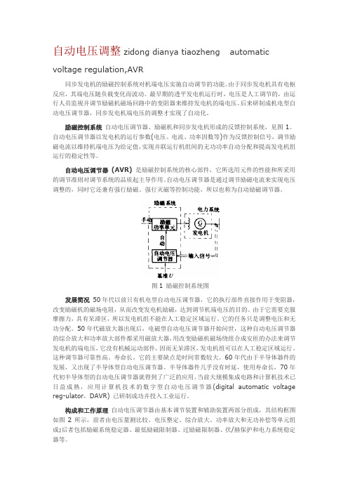
自动电压调整zidong dianya tiaozheng automaticvoltage regulation,AVR同步发电机的励磁控制系统对机端电压实施自动调节的功能。
由于同步发电机具有电枢反应,其端电压随负载变化而波动。
最早期的透平发电机运行时,电压是人工调节的,由运行人员监视并调节励磁机磁场回路中的变阻器来维持发电机的端电压。
后来研制成机电型自动电压调节器,同步发电机端电压的调整才实现了自动化。
励磁控制系统自动电压调节器、励磁机和同步发电机形成的反馈控制系统,见图1。
自动电压调节器以发电机的运行参数(电压、电流、功率因数等)作为反馈控制信号,调节励磁电流以维持机端电压为给定值,实现并联运行机组间的无功功率自动分配和提高发电机组运行的稳定性等。
自动电压调节器(AVR)是励磁控制系统的核心部件,它所选用元件的性能和所采用的调节准则对调节系统的品质起主导作用。
自动电压调节器是通过调节励磁电流来实现电压调整的,同时它还兼有强行励磁、强行灭磁等控制功能,所以也称为自动励磁调节器。
图1 励磁控制系统图发展简况50年代以前只有机电型自动电压调节器,它的执行部件直接作用于变阻器,改变励磁机的磁场电阻,从而改变发电机励磁,达到调节机端电压的目的。
由于它需要克服摩擦力,具有呆滞区,所以发电机组不能在人工稳定区域运行。
它的任务只是调整电压和无功分配。
50年代磁放大器出现后,电磁型自动电压调节器开始问世,这种自动电压调节器的综合放大和功率放大部件都采用磁放大器,用改变励磁机磁场绕组合成安匝的办法来调节发电机的端电压,它没有机械运动部件,因而无呆滞区,发电机组可以在人工稳定区域运行。
这种调节器可靠性高、寿命长。
它的主要缺点是时间常数较大。
60年代由于半导体器件的发展,又出现了半导体型自动电压调节器。
半导体器件几乎没有时延,使用寿命长,70年代初半导体型的自动电压调节器就得到了广泛的应用。
当前大规模集成电路和计算机技术已日益成熟,应用计算机技术的数字型自动电压调节器(digital automatic voltage reg-ulator,DAVR) 已研制成功并投入工业运行。
SX440电压调整器AVR使用说明
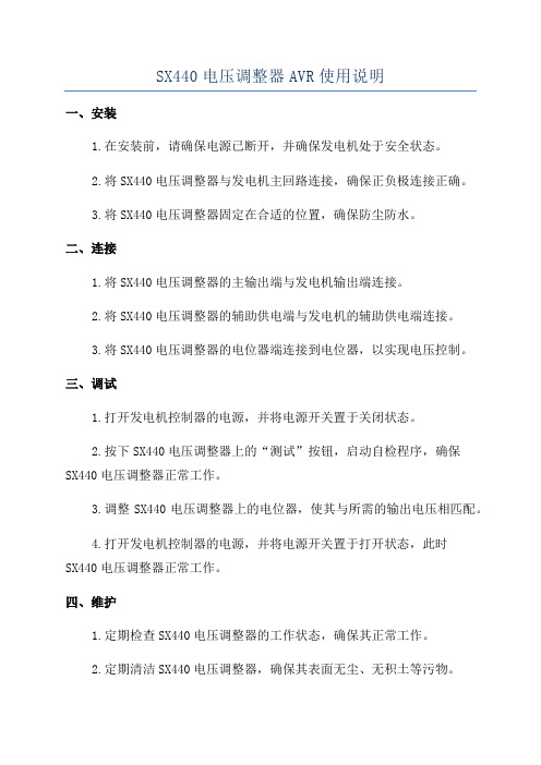
SX440电压调整器AVR使用说明一、安装1.在安装前,请确保电源已断开,并确保发电机处于安全状态。
2.将SX440电压调整器与发电机主回路连接,确保正负极连接正确。
3.将SX440电压调整器固定在合适的位置,确保防尘防水。
二、连接1.将SX440电压调整器的主输出端与发电机输出端连接。
2.将SX440电压调整器的辅助供电端与发电机的辅助供电端连接。
3.将SX440电压调整器的电位器端连接到电位器,以实现电压控制。
三、调试1.打开发电机控制器的电源,并将电源开关置于关闭状态。
2.按下SX440电压调整器上的“测试”按钮,启动自检程序,确保SX440电压调整器正常工作。
3.调整SX440电压调整器上的电位器,使其与所需的输出电压相匹配。
4.打开发电机控制器的电源,并将电源开关置于打开状态,此时SX440电压调整器正常工作。
四、维护1.定期检查SX440电压调整器的工作状态,确保其正常工作。
2.定期清洁SX440电压调整器,确保其表面无尘、无积土等污物。
3.定期检查SX440电压调整器的连接线路,确保其稳固可靠。
五、常见问题解答1.SX440电压调整器如何连接到发电机?答:将SX440电压调整器的主输出端与发电机输出端连接即可。
2.如何调整SX440电压调整器的输出电压?答:通过调整SX440电压调整器上的电位器可以实现输出电压的调整。
3.SX440电压调整器出现故障时应该怎么办?4.SX440电压调整器的最大输出电压是多少?答:SX440电压调整器的最大输出电压一般为220V。
六、注意事项1.安装、调试和维护SX440电压调整器时,请务必断开电源以确保安全。
2.在操作SX440电压调整器时,请仔细阅读并遵守使用说明。
4.在连接线路时,请确保连接正确并稳固可靠。
SX440电压调整器AVR使用说明
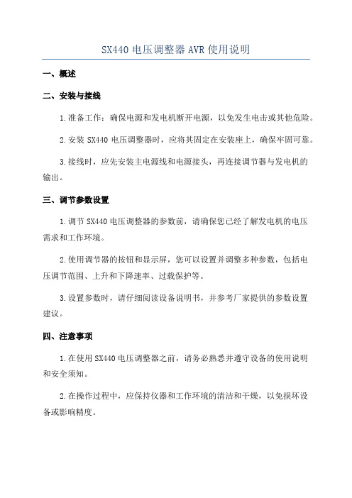
SX440电压调整器AVR使用说明
一、概述
二、安装与接线
1.准备工作:确保电源和发电机断开电源,以免发生电击或其他危险。
2.安装SX440电压调整器时,应将其固定在安装座上,确保牢固可靠。
3.接线时,应先安装主电源线和电源接头,再连接调节器与发电机的
输出。
三、调节参数设置
1.调节SX440电压调整器的参数前,请确保您已经了解发电机的电压
需求和工作环境。
2.使用调节器的按钮和显示屏,您可以设置并调整多种参数,包括电
压调节范围、上升和下降速率、过载保护等。
3.设置参数时,请仔细阅读设备说明书,并参考厂家提供的参数设置
建议。
四、注意事项
1.在使用SX440电压调整器之前,请务必熟悉并遵守设备的使用说明
和安全须知。
2.在操作过程中,应保持仪器和工作环境的清洁和干燥,以免损坏设
备或影响精度。
4.SX440电压调整器只能由专业人士进行安装、维修和维护,任何未经授权的操作可能导致设备损坏或人身伤害。
5.在调节器运行过程中,请注意观察设备的状态和指示灯的显示,及时处理问题。
6.在断开电源或停机时,请先关闭电压调整器,再切断电源,以免电击或其他危险。
五、常见问题与解决
1.问题:SX440电压调整器无法调节电压。
2.问题:SX440电压调整器发出异常噪音。
3.问题:SX440电压调整器显示屏无法正常显示。
4.问题:SX440电压调整器参数设置无效。
发电机AVR

转 速 %
(Hz)
发动机转速
20 40 60 80 100 120
100 80
% VOLTS
LED OFF
60 40 20
NEWAGE PRODUCT TRAINING
10
AVR 控制
高励磁保护线路
励磁跳闸
发光二极管 (LED)
按照标准设置所有的MA和MX的AVR均应带PMG 控制调节工厂是密封的,在没有工厂的建议情况下,不要擅自改变 70-运75行V的直水流平 (跳闸水平)是通过励磁定子的接线端 X+(F1) 和 XX- (F2)被设置在
(L.E.D)
协助发动机恢复 对于涡流发动机组特别有用 发动机控制, 下降控制可取得最佳 过大的电压下降,可能影响电线上其它电器
NEWAGE PRODUCT TRAINING
14
AVR 控制 - 恢复时间延迟控制
时调间节延迟
发光二极管 UFRO
(L.E.D)
恢复时间延迟是同频率过低导致电压下降一起使用的, (当 UFRO 线路闭 合时)
自动电压调节器 型号 (AVR)
AS440 P/N E000-24403
Automatic Voltage Regulator (AVR) Type AS440 P/N E000-24403
F2 F1 7 8
8 Z2
121K
48300 C1334 R6- µ33 M275V
n J1000 w
E00-14065A
自动电压调节器 (AVR) MX321 P/N E000 -23212
P4
K2 K1 P2 P3
P4 XX X 6
7 8 12
VOLTS
RAMP
SX440自动电压调节器(AVR)规格、安装和调节说明书
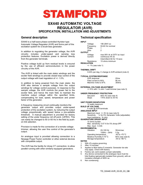
DESIGN DETAILSX440 AUTOMATIC VOLTAGEREGULATOR (AVR)SPECIFICATION, INSTALLATION AND ADJUSTMENTS General description Technical specificationSX440 is a half-wave phase-controlled thyristor type Automatic Voltage Regulator (AVR) and forms part of the excitation system for a brush-less generator.In addition to regulating the generator voltage, the AVR circuitry includes under-speed and sensing loss protection features. Excitation power is derived directly from the generator terminals.Positive voltage build up from residual levels is ensured by the use of efficient semiconductors in the power circuitry of the AVR.The AVR is linked with the main stator windings and the exciter field windings to provide closed loop control of the output voltage with load regulation of +/- 1.0%.In addition to being powered from the main stator, the AVR also derives a sample voltage from the output windings for voltage control purposes. In response to this sample voltage, the AVR controls the power fed to the exciter field, and hence the main field, to maintain the machine output voltage within the specified limits, compensating for load, speed, temperature and power factor of the generator.A frequency measuring circuit continually monitors the generator output and provides output under-speed protection of the excitation system, by reducing the output voltage proportionally with speed below a pre-settable threshold. A manual adjustment is provided for factory setting of the under frequency roll off point, (UFRO). This can easily be changed to 50 or 60 Hz in the field by push-on link selection.Provision is made for the connection of a remote voltage trimmer, allowing the user fine control of the generator's output.An analogue input is provided allowing connection to a Newage Power Factor controller or other external devices with compatible output.The AVR has the facility for droop CT connection, to allow parallel running with other similarly equipped generators. INPUTVoltage 190-264VacFrequency 50-60 Hz nominalPhase 1Wire 2OUTPUTVoltage max 90V dc at 207V ac inputCurrent continuous 4A dcIntermittent 6A for 10 secsResistance 15 ohms minimumREGULATION+/- 1% (see note 1)THERMAL DRIFT0.04% per deg. C change in AVR ambient (note 2)TYPICAL SYSTEM RESPONSEAVR response 20msFiled current to 90% 80 msMachine Volts to 97% 300msEXTERNAL VOLTAGE ADJUSTMENT+/-10% with 1 k ohm 1 watt trimmer (see note 3)UNDER FREQUENCY PROTECTIONSet point 95% Hz (see note 4)Slope 170% down to 30 HzUNIT POWER DISSIPATION12 watts maximumBUILD UP VOLTAGE4 Volts @ AVR terminalsANALOGUE INPUTMaximum input +/- 5V dc (see note 5)Sensitivity 1v for 5% Generator Volts (adjustable)Input resistance 1k ohmQUADRATURE DROOP INPUT10 ohms burdenMax. sensitivity: 0.07 A for 5% droop 0PFMax. input: 0.33AENVIRONMENTALVibration 20-100Hz 50mm/sec100Hz – 2kHz 3.3gOperating temperature -40 to +70 o CRelative Humidity 0-70 o C 95% (see note 6)Storage temperature -55 to +80 o C NOTES1. With 4% engine governing.2. After 10 minutes.3. Applies to Mod status S onwards. Generator de-ratemay apply. Check with factory.4. Factory set, semi-sealed, jumper selectable.5. Any device connected to the analogue input must befully floating (galvanically isolated from ground), with an insulation strength of 500V ac.6. Noncondensing.DESIGN DETAILThe main functions of the AVR are:Potential Divider and Rectifier takes a proportion of the generator output voltage and attenuates it. The potential divider is adjustable by the AVR Volts potentiometer and external hand trimmer (when fitted). The output from the droop CT is also added to this signal. An isolating transformer is included allowing connection to various winding configurations. A rectifier converts the a.c. input signal into d.c. for further processing.The Sensing Loss Detector is an electronic changeover switch, which normally connects the Amplifier (Amp) to the Voltage Sensing input and automatically changes over to the Power input when the normal sensing voltage is lost.The DC Mixer adds the Analogue input signal the Sensing signal.The Amplifier (Amp) compares the sensing voltage to the Reference Voltage and amplifies the difference (error) to provide a controlling signal for the power devices. The Ramp Generator and Level Detector and Driver infinitely control the conduction period of the Power Control Devices and hence provides the excitation system with the required power to maintain the generator voltage within specified limits.The Stability Circuit provides adjustable negative ac feedback to ensure good steady state and transient performance of the control system.The Low Hz Detector measures the period of each electrical cycle and causes the reference voltage to be reduced approximately linearly with speed below a presettable threshold. A Light Emitting Diode gives indication of underspeed running.The Synchronising circuit is used to keep the Ramp Generator and Low Hz Detector locked to the generator waveform period.The Low Pass Filter prevents distorted waveforms affecting the operation of the AVR control circiutPower Control Devices vary the amount of exciter field current in response to the error signal produced by the Amplifier.Suppression components are included to prevent sub cycle voltage spikes damaging the AVR components and also to reduce the amount of conducted noise on the generator terminals..The Power Supply provides the required voltages for the AVR circuitry.Hand Trimmer Analogue Input DroopFITTING AND OPERATINGSUMMARY OF AVR CONTROLSCONTROL FUNCTION DIRECTIONVOLTS TO ADJUST GENERATOR OUTPUT VOLTAGE CLOCKWISE INCREASES OUTPUT VOLTAGE STABILITY TO PREVENT VOLTAGE HUNTING CLOCKWISE INCREASE THE DAMPING EFFECTUFRO TO SET THE UFRO KNEE POINT CLOCKWISE REDUCES THE KNEE POINTFREQUENCYDROOP TO SET THE GENERATOR DROOP TO 5% AT 0PF CLOCKWISE INCREASES THE DROOPVTRIM TO OPTIMISE ANALOGUE INPUT SENSITIVITY CLOCKWISE INCREASES THE GAIN OR SENSITIVITY ADJUSTMENT OF AVR CONTROLSVOLTAGE ADJUSTMENTThe generator output voltage is set at the factory, but can be altered by careful adjustment of the VOLTS control on the AVR board, or by the external hand trimmer if fitted. Terminals 1 and 2 on the AVR will be fitted with a shorting link if no hand trimmer is required.CAUTION Do not increase the voltage above the rated generator voltage. If in doubt, refer to the rating plate mounted on the generator case.CAUTION Do not ground any of the hand trimmer terminals as these could be above earth potential. Failure to observe this could cause equipment damage.If a replacement AVR has been fitted or re-setting of the VOLTS adjustment is required, proceed as follows: CAUTION1. Before running generator, turn the VOLTS control fully anti-clockwise.2. Turn remote volts trimmer (if fitted) to midway position.3. Turn STABILITY control to midway position.4. Connect a suitable voltmeter (0-300V ac) acrossline to neutral of the generator.5. Start generator set, and run on no load at nominal frequency e.g. 50-53Hz or 60-63Hz.6. If the red Light Emitting Diode (LED) is illuminated, refer to the Under Frequency Roll Off (UFRO) adjustment.7. Carefully turn VOLTS control clockwise until rated voltage is reached.8. If instability is present at rated voltage, refer to stability adjustment, then re-adjust voltage if necessary.9. Voltage adjustment is now completed.FITTING AND OPERATINGTD_SX440 AVR_03.06_04_GBBarnack Road • Stamford • Lincolnshire • PE9 2NB Tel: 00 44 (0)1780 484000 • Fax: 00 44 (0)1780 484100© 2006 Cummins Generator Technologies Limited.STABILITY ADJUSTMENTThe AVR includes a stability or damping circuit to provide good steady state and transient performance of the generator.The correct setting can be found by running the generator at no load and slowly turning the stability control anti-clockwise until the generator voltage starts to become unstable.The optimum or critically damped position is slightly clockwise from this point (i.e. where the machine volts are stable but close to the unstable region).OPTIMUM RESPONSE SELECTIONThe stability selection ‘jumper’ should be correctly linked, A-B, B-C or A-C at the bottom of the board for the frame size of the generator, (see drawing).UNDER FREQUENCY ROLL OFF (UFRO) ADJUSTMENTThe AVR incorporates an underspeed protection circuit which gives a volts/Hz characteristic when the generator speed falls below a presettable threshold known as the "knee" point.The red Light Emitting Diode (LED) gives indication that the UFRO circuit is operating.The UFRO adjustment is preset and sealed and only requires the selection of 50 / 60Hz using the jumper link.For optimum setting, the LED should illuminate as the frequency falls just below nominal, i.e. 47Hz on a 50Hz system or 57Hz on a 60Hz system.DROOP ADJUSTMENTGenerators intended for parallel operation are fitted with a quadrature droop C.T. which provides a power factor dependent signal for the AVR. The C.T. is connected to S1, S2 on the AVR.The DROOP adjustment is normally preset in the works to give 5% voltage droop at full load zero power factor.Clockwise increases the amount of C.T. signal injected into the AVR and increases the droop with lagging power factor (cos Ø). With the control fully anti-clockwise there is no droop.TRIM ADJUSTMENTAn analogue input (A1 A2) is provided to connect to the Newage Power Factor Controller or other devices. It is designed to accept dc signals up to +/- 5 volts.CAUTION Any devices connected to this input must be fully floating and galvanically isolated from ground, with an insulation capability of 500 Vac. Failure to observe this could result in equipment damage.The dc signal applied to this input adds to the AVR sensing circuit. A1 is connected to the AVR 0 volts. Positive on A2 increases excitation. Negative on A2 decreases excitation.The TRIM control allows the user to adjust the sensitivity of the input. With TRIM fully anti-clockwise the externally applied signal has no effect. Clockwise it has maximum effect.Normal setting is fully clockwise when used with a Newage Power Factor Controller.。
- 1、下载文档前请自行甄别文档内容的完整性,平台不提供额外的编辑、内容补充、找答案等附加服务。
- 2、"仅部分预览"的文档,不可在线预览部分如存在完整性等问题,可反馈申请退款(可完整预览的文档不适用该条件!)。
- 3、如文档侵犯您的权益,请联系客服反馈,我们会尽快为您处理(人工客服工作时间:9:00-18:30)。
A VR自动电压调压器
AVR是英文automatic voltage regulator的缩写,是三相同步发电机的重要部件。
AVR是一种半波相近控制闸流管型的自动电压调节器,是交流发电机励磁系统的一部分。
除调节发电机的电压外,AVR还具有低速和无检测信号保护的功能,以保证对发电机安全可靠的控制,励磁电源直接由发电机输出端导出。
AVR电源电路使用的高效半导体保证了由剩磁获得的起励电压。
西电SDMO小功率机组mecc alte spa电球普遍采用SR7 AVR,LEROY SOMER电球采用R230、R448、R449等AVR。
其工作原理都差不多,AVR与主定子绕组和励磁绕组连接,对输出电压提供精度为±1%的闭环控制。
在从主定子获得电源外,AVR还从输出绕组取样电压以实现对输出的控制。
AVR根据获得的采样数据控制输出到励磁系统的电流,通过可控硅导通角的调节,把无功功率、功率因数和输出电压控制在一定的范围内。
国产和印度机的AVR接线方式一样,只需要连接E+、E-和U、V相绕组取样电压和零线,根据取样电压与设定电压的误差放大,经脉宽调制,通过可控硅导通角的调节控制输出励磁电流从而调节发电机的输出电压。
上一个虚线框为A VR的功能块,主要的自动调压功能由这一部分完成,下一个虚线框为A VR的保护块,对发电机的低速和超载进行保护。
“VOLT” Set point 电压设定点
Error amplifier 误差放大器
Stability network 网络稳定度
Pulse width modulation 脉宽调制
Field voltage 磁场电压
Output voltage 输出电压
Sensing 检测Delay 延时angle 角
SR7
R230 R448
耐维和印度机AVR的接线
R230 AVR的接线和电位计
R448的接线方式
R448的电位计
T22机组AVR接线
1、3 E+、E- /3A、5磁场(电压反馈辅助输出) /4、5C定子绕组(电压取样)
T11.5机组AVR接线
1、3 E+、E- /4A、5定子绕组(电压取样) /3A、4磁场(电压反馈辅助输出))。