过程控制-专业英语-第一章
过程装备与控制工程专业英语词汇
steam generator 蒸汽发生器,蒸汽锅炉
stir 搅拌
strength强度
stress 应力
stroke 冲程,行程
stuffing填料
suction 抽吸;吸力
summary 概要;总结
superheated steam 过热蒸汽
surface表面
surrounding环境
manometer压力计
manufacture制造,生产
measurement测量,量;量法
mechanical机械的,力学的
membrane薄膜
mesh啮合,网格
metal金属
modular模块化的;有标准组件的
moisture水分,湿度
molecule分子
molten熔化的;铸造的
monitor监控,监督
counter flow 逆流
crack 裂缝,裂纹
cracking 裂化
crankshaft 曲轴
cross-flow 横向流,交叉流
cross-sectional area 横截面面积
crystal 晶体,结晶
cyclone 气旋,旋风
cylinder 圆筒,气缸
cylindrical furnace 圆筒炉
lining衬里
linkage连接,连锁,连杆机构
lobe pump罗茨泵
longitudinal纵向的;经度的
loop环,回路
louver天窗,百叶窗
lubricant润滑剂
lubrication润滑
magenatic有磁性的,地磁的
maintenance维护,维修;保持
makeup补给,补充,组成
过程装备与控制工程专业英语翻译part.ⅰ(课文阅读材料)综合各版精华

PART I 力学基础知识█Unit 1力系的一般平衡条件 在这一节,我们将研究为了使一个物体保持平衡,作用在其上的力和力偶所必须满足的条件。
根据牛顿第一定律,施加在一个静止物体上的力系的合力一定为零。
然而,请注意这个定律对力矩或力系的转动效应只字未提。
显然,合力矩也一定为零,否则物体将会转动。
这里的基本问题是,按照先前的规定,牛顿第一定律(和第二定律)只适用于非常小的物体,或者尺寸可以忽略的非零质量的质点。
然而,它可以推广到下述有限尺寸的物体。
考虑一个由两个质点组成的系统,并假设1f 和2f 是由于它们之间相互作用产生的力(图.1.1)。
这些力称为内力,因为它们是由于系统内部的物体之间的相互作用而产生的。
假定内力服从牛顿第三定律,我们有12f f =-。
假如还有质点与系统外物体相互作用产生的力施加在质点上,如1,2F F 和3F ,这些力称为外力。
显然,作用在某个特定质点上的力一定有相同的作用点,因为质点的尺寸可以忽略。
如果系统内的每一个质点处于平衡,我们就可以说系统是平衡的。
这种情况下,依据牛顿第一定律,作用在每个质点上的力的合力一定为零。
对质点A 我们有:∑=++=0121f F F F A而对质点B 有: ∑032=+=F f F B 作用在系统上的力的总和为:123120A B F F FF F F f f =+=++++=∑∑∑ 现在让我们来研究这些力对于某一点P 的合力矩。
参照图1.1,我们有: 12()()P A B Mr F r F =⨯+⨯∑∑∑ 其中0==∑∑B A F F ;如前所述,那么合力矩也一定为零。
由于力1f 和2f 有相同的作用线,力矩的平衡条件可以改写为:1121223()0P Mr F F f f r F =⨯++++⨯=∑ 其中12f f =-;因此力和力矩的平衡条件就简化为:0321=++=∑F F F F 和 111223()()()0P M r F r F r F =⨯+⨯+⨯=∑换句话说,如果系统处于平衡,那么作用在上面的外力和一定为零,并且这些外力对任一点的合力矩也一样为零。
过程装备与控制工程专业英语

######Manufacturing Engineering Processes1.Classification of Manufacturing ProcessesThe following table shows the classification of manufacturing engineering processes used in shaping materials. Note that only typical examples are mentioned in the table.2.Examples of Manufacturing ProcessesForging .Forging can be characterized as: mass conserving, solid state of work material (metal), mechanical primary basic process-plastic deformation. A wide variety of forging processes is used .The most common type of forging is drop forging .The metal is heated to a suitable working temperature and placed in the lower die cavity .The upper die is then lower so that the metal is forced to fill the cavity. Excess material is squeezed out between the die faces at the periphery as flash, which is removed in a later trimming process. When the term gorging is used, it usually means hot gorging. The material loss in forging processes is usually quite small. Normally, forged components require some subsequent machining, since thetolerances and surfaces obtainable are not usually satisfactory a finished product. Forging machines include drop hammers and forging presses with mechanical or hydraulic drives. Es involve simple .The machines involve simple translatory motions.Rolling Rolling can be characterized as: mass conserving, solid state of material, mechanical primary basic process-plastic deformation. Rolling is extensively used in the manufacturing of plates, sheets, structural beams, and so on. An ingot is produced in casting, and then, in several stages of rolling it is reduced in thickness, usually while hot. Since the width of the work material is kept constant, its length is increased according to the reduction. After the last hot-rolling stage, a final stage is carried out cold to improve surface quality and tolerances and to increase strength. In rolling, the profiles of the rolls designed to produce the desired geometry.Powder Compaction Powder compaction can be characterized as; mass conserving, granular state of material, mechanical primary basic process-flow and plastic deformation. In this context, only compaction of metal powder is mentioned, but generally compaction of molding sand, ceramic materials, and so on, also belong in this category.In the compaction of metal powders, the die cavity is filled with a measured volume of powder and compacted at pressures typically around 500N/mm2. During this pressing phase, the particles are packed together and plastically deformed. Typical densities after compaction are 80% of the density of the solid material. Because of the plastic deformation, the particles are”welded” together, giving sufficient strength to withstand handling. After compaction, the components are heat-treated—sintered—normally at 70%~80% of the melting temperature of the material. The atmosphere for sintering must be controlled to prevent oxidation. The duration of the sintering process varies between 30 min and 2h. The strength of the components after sintering can, depend on the material and the process parameters closely approach the strength of corresponding solid material.The die cavity, in the closed position, corresponds to the desired geometry. Compaction machinery includes both mechanical and hydraulic presses. The production rates vary between 6 and 100 components per minute.加工工艺过程1.加工工艺过程的分类2.锻造工艺过程分类锻造锻造过程的特性可表述如下,质量守恒,工作材料为固态,力学基本过程为塑性变形过程。
专业英语-吐血整理

plant 车间、工厂、系统process control 过程控制quality 质量inlet 入口、进口constant 常数、恒量set point 设定值terminology 术语gradient 梯度energy balance 能量平衡manual control 手动控制automatic control自动控制heat sink 散热片散热装置negative feedback负反馈positive feedback 正反馈feedforward control前馈控制heat exchanger 热交换器performance履行;实行、演出、成绩process plant 车间工序reference 提及、涉及operating condition 操作环境disturbance 干扰controlled variable控制变化带搅拌加热器stirred-tank heater密度density比热容specific heat capacity热容热损失heat loss前馈控制策略~strategy控制器controlleroversimplify 过于简化bandwidth 带宽误差范围gain 增益sensitivity 灵敏度numerous 众多的大量的static-system静态系统magnitude 大小幅值phase 相角相位resistance 电阻阻抗thermal-noise 热噪声transient response瞬时响应frequency response频率响应stability稳定性actuator 执行器sensor传感器transducer 传感器linear quadratic regulator线性二次型调节器simulation 刺激flow rate流速concertration浓度level 水平水准闭环closed loop开环open loop可编程逻辑控制器PLC(programmable logic controller)模型model经验模型empircal modeling比例proportional比例加微分proportional plus derivative比例加积分proportional plus integral criterion 判据准则oscillatory 振动的amplitude 振幅振荡undamped 无阻尼的无衰减的polynomial 多项式saturation 饱和unconstrained 自由的无约束的characteristic equation 特征方程distinct pole 孤立极点coefficient 系数matrix 矩阵damp 阻尼衰减unstable 不稳定的complex numbermanipulated variable操纵变量load variable 负载变量processtransfer function传递函数pole-zero cancellation 零极点相消self-regulating 自我调节拉氏变换Laplace transform零点zero point极点pole point偏差变量omitted variable bias比较器comparator伺服问题servo problem给定变化Given Variableretard 延迟anarchy 混乱methodology 方法论constraint 约束强制productivity 生产力多产investment 投资投入fundamental基础的原始的evaluating 评价distillation column蒸馏塔process dynamic 过程动态manipulatable input操作输入observable output可观输出measurable disturbance可测扰动炼油oil refining电力electric power再沸器reboiler航空航天aerospacecontroller tuning 控制器整定trail and error 试差法time-consuming 耗时的residence time滞留时间decay ratio 衰减比overshoot 超调calibration 刻度标度guideline指导方针averaging control 平均控制eliminate 消除排除ultimate gain最年夜增益continuous cycling method连续循环方法process reaction curve method过程反应曲线法container 容器metric unit 公制单位atmospheric pressure大气压absolute pressure绝压guage pressure 表压differential pressure 差压diaphragm膜片膜盒capsule 膜盒容器bellows 风箱波纹管Bourdon tube波登管stainless steel 不锈钢strain gauge应变仪capacitance 容量电容semiconductor半导体total vacuum 全真空silicon diaphragm硅膜压力传感器pressure sensor差压变送器differential pressure transmitter 压力传感元件Pressure sensing element波登管压力表Wave tube pressure gauge overflow溢出溢流uninterrupted不停地连续的specific weight比重buoyancy 浮力浮力性immerse 浸没沉入capacitive probe电容电极dielectric constant 介电常数pressurized container带压容器hazardous 危险的易爆的level measurement物位测量interface 接触面电位计potentiometer导电电极the conductive electrode超声波 ultrasonic wave荷重传感器 load sensoraccounting统计计算velocity 速度laminater flow 层流turbulent flow 湍流viscosity 黏性黏度centistoke 厘沱Reynolds number R雷诺数Rflow patterns流型,流动形式flow rate 流率流速total flow总体流速continuity equation连续方程acc of gravity重力加速度kinetic energy 动能potential energy势能restriction 局限orifice plate 量孔板venturi tube 文丘里管flow nozzle 流量喷管rotameter 转子流速计mass flow 质量流量能量守恒conservation of energy摩擦力 frictiondamper 阻尼器制动器风门valve positioner 阀门定位器gear 齿轮control valve 控制阀electric motor actuator电机驱动器variable speed pump 可变速泵fail-safe action 故障安全行动diaphragm area 隔膜面积pneumatic pressure气动压力converters 转换器控制性能control performance最终控制元件final control element电磁阀 electromagnetic valve阀特性valve characteristicssphere 范围球体fundamental standard 基本标准absolute standard绝对标准thermoelectric effect热电势效应resistance change电阻变化thermography热像仪thermal expansion热膨胀resonant frequency回声频率fiber optic光纤acoustic thermometry声学测温术ceramic beaded陶制珠状的junction联络点热电偶 thermocouple热电阻 RTD沸点 boiling point冰点 freezing point固态 solid state液态 liquid state气态 gaseous state电动势e、m、f隔离isolated物理原理 physical principle国际实际温标IPTS(international practicl temperature scale)。
过程装备与控制工程专业英语
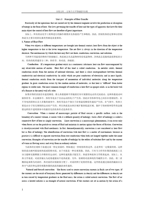
Unit 13 Principles of Heat TransferPractically all the operations that are carried out by the chemical engineer involve the production or absorption of energy in the form of heat. The laws governing the transfer of heat and the types of apparatus that have for their main object the control of heat flow are therefore of great importance.实际上,所有的由化学工程师进行的操作都要涉及热量的产生和吸收。
因此,控制传热的定律和以控制热流为主要目的的仪器类型都是很重要的。
1. Nature of Heat FlowWhen two objects at different temperatures are brought into thermal contact, heat flows from the object at the higher temperature to that at the lower temperature. The net flow is always in the direction of the temperature decrease. The mechanisms by which the heat may flow are three, conduction, convection, and radiation.当两种不同温度的物体开始接触后,热流就会从高温物体传给低温物体。
净热流总是随着温度降低的方向。
传热的机理通常分三种:热传导,热对流,热辐射。
过程装备与控制工程专业英语翻译1
过程装备与控制工程专业英语本文为过程装备与控制工程专业英语的个人翻译尝试。
By LiyerPART 1 engineering mechanicUnit 1 introduction to mechanicof materials材料力学是应用力学的分支,用于解决固体遭受外部多种载荷产生的力学行为。
对这个课题领域的另外的称呼有材料强度与固体变形的力学。
本章节提及固体包括经受轴向载荷的杆、扭转的轴、弯曲的梁和被压缩的圆柱。
材料力学研究的主要目标是在外部载荷加载的时候确定结构的应力、压力和应变以及固体微元的具体变化。
如果能够得到物体从受载到失效的所有与载荷对应的这些物理量,我们就对物体的力学性能有了一个全面的了解。
对力学行为的理解对于各种类型结构的安全设计是十分必要的,不管是飞机和天线、建筑和桥梁、机器和发动机、或者是船和飞行器。
这就是材料力学在这么多工程领域里都属于基础学科的原因。
静力学和动力学也是基本的,但是这些学科主要解决与粒子和刚体相关的力和运动问题。
在材料力学中,我们可以通过检测一个在有限维度内受力变形的实物的应力和应变来进一步学习。
而为了确定应力和应变,我们一般使用材料的物理性质以及一些理论公式和概念。
理论分析和实验结果在材料力学中也扮演着重要的角色。
我们从理论中为预测力学状态导出了准则和公式,但这些表达方式不能被用于实际的设计中,除非材料的物性已知。
只有通过在实验室细心的实验测试,我们方能得到材料的物性。
而且,并不是所有实际问题都能通过理论分析来解决,在这种情况下,物性试验就是必要的了。
材料力学的发展是理论和实验的有趣的结合-理论有时候指明了可以得到重大进展的路,有时候实验也做到这一点。
一些著名的科学家,如Leonardo da Vinci和Galileo Galilei通过实验确定绳索、杆和梁等的强度,尽管从今天的观点,他们没有得出详尽的理论体系来解释他们的实验结果。
相反的,著名的数学家Leonhard Euler在1744年得出了圆柱体的数学理论并且计算了圆柱体的临界载荷,远早于任何能够证明他的结果重要性的实验证据出现。
过程装备与控制工程专业英语
过程装备与控制工程专业英语学院:化学化工学院1.Static Analysis of Beams⑴ A bar that is subjected to forces acting trasverse to its axis is called a beam. In this section weconsider only a few of the simplest types of beams, such as those shown in Flag.1.2. In every instance it is assumed that the beam has a plane of symmetry that is parallel to the plane of the figure itself. Thus , the cross section of the beam has a vertical axis of symmetry .Also,it is assumed that the applied loads act in the plane of symmetry ,and hence bending of the beam occurs in that plane. Later we will consider a more general kind of bending in which the beam may have an unsymmetrical cross section.⑵ The beam in Fig.1.2, with a pin support at one end and a roller support at the other, is calleda simply support beam ,or a simple beam . The essential feature of a simple beam is that both ends of the beam may rotate freely during bending, but the cannot translate in lateral direction. Also ,one end of the beam can move freely in the axial direction (that is, horizontal). The supports of a simple beam may sustain vertical reactions acting either upward or downward .⑶ The beam in Flg.1.2(b) which is built-in or fixed at one end and free at the other end, iscalled a cantilever beam. At the fixed support the beam can neither rotate nor translate, while at the free end it may do both. The third example in the figure shows a beam with an overhang. This beam is simply supported at A and B and has a free at C.⑷ Loads on a beam may be concentrated forces, such as P1 and P2 in Fig.1.2(a) and (c), ordistributed loads loads, such as the the load q in Fig.1.2(b), the intesity. Distributed along the axis of the beam. For a uniformly distributed load, illustrated in Fig.1.2(b),the intensity is constant; a varying load, on the other hand, is one in which the intensity varies as a function of distance along the axis of the beam.⑸ The beams shown in Fig.1.2 are statically determinate because all their reactions can bedetermined from equations of static equilibrium. For instance ,in the case of the simple beam supporting the load P 1 [Fig.1.2(a)], both reactions are vertical, and tehir magnitudes can be found by summing moments about the ends; thus,we findL a L P R A )(1-= LL P R B 1= The reactions for the beam with an overhang [Fig.1.2 (c)]can be found the same manner.⑹ For the cantilever beam[Fig.1.2(b)], the action of the applied load q is equilibrated by avertical force RA and a couple MA acting at the fixed support, as shown in the figure. From a summation of forces in certical direction , we include thatqb R A =, And ,from a summation of moments about point A, we find)2(b a qb M A +=, The reactive moment MA acts counterclockwise as shown in the figure.⑺ The preceding examples illustrate how the reactions(forces and moments) of staticallydeterminate beams requires a considerition of the bending of the beams , and hence this subject will be postponed.⑻ The idealized support conditions shown in Fig.1.2 are encountered only occasionally inpractice. As an example ,long-span beams in bridges sometimes are constructionn with pin and roller supports at the ends. However, in beams of shorter span ,there is usually some restraint against horizonal movement of the supports. Under most conditions this restraint has little effect on the action of the beam and can be neglected. However, if the beam is very flexible, and if the horizonal restraints at the ends are very rigid , it may be necessary to consider their effects.⑼ Example Find the reactions at the supports for a simple beam loaded as shown infig.1.3(a ). Neglect the weight of the beam.⑽ Solution The loading of the beam is already given in diagrammatic form. The nature of thesupports is examined next and the unknow components of reactions are boldly indicated on the diagram. The beam , with the unknow reaction components and all the applied forces, is redrawn in Fig.1.3(b) to deliberately emphasiz this important step in constructing a free-body diagram. At A, two unknow reaction components may exist , since roller. The points of application of all forces are carefully noted. After a free-body diagram of the beam is made, the equations of statics are applied to abtain the sollution.∑=0x F ,R Ax =0∑+=0A M ,2000+100(10)+160(15)—R B =0,R B =+2700lb ↑∑+=0BM ,RAY(20)+2000—100(10)—160(5)=0,RAY=—10lb ↓ Check :∑+↑=0FX ,—10—100—160+270=0 ⑾ Note that ∑=0x F uses up one of the three independent equations of statics, thus only twoadditional reaction compones may be determinated from statics. If more unknow reaction components or moment exist at the support, the problem becomes statically indeterminate. ⑿ Note that the concentrated moment applied at C enters only the expressions for summationmoments. The positive sign of RB indicates that the direction of RB has been correctly assumed in Fig.1.3(b). The inverse is the case of RAY ,and the vertical reaction at a is downward. Noted that a check on the arithmetical work is available if the caculations aremade as shown.横梁的静态分析⑴ 一条绕其轴水平放置的棒就是所谓的横梁,本章节我们将研究最简单的横梁模型形式,如图1.2所示。
自动化专业英语第三版王树青第一章翻译
自动化专业英语第三版1.1 介绍过程控制1.近年来,对过程系统的性能改善需求变得越来越困难. 更为激烈的竞争,更加严格的环境和安全规范,以及快速变化的经济条件都是加强工厂产品质量规范的关键因素2.更为复杂的情况是,由于现代制造业朝着规模更大,集成度更高的方向发展,而使不同的加工环节之间的协调能力更低, 所以加工过程更难控制.在这种工厂中,要想让一个生产环节出现的问题不对其相连的另一个生产环节产生影响,几乎是不可能的.3.近年来,考虑到工业制造逐渐加强的安全、高效需求,过程控制这个课题变得越来越受重视.实际上,对于大多数现代工业,要满足安全、高效,产品质量的要求,没有控制系统是不可能的.1.1.1说明性的例子1.图1.1.1 所示的连续加热搅拌器可以作为过程控制的典型例子.输入液态流体的质量流量率为w,温度为Ti. 槽内成分搅拌均匀,并且用电加热器,功率为Q瓦特.2.假设输入和输出流量率是相等的,并且液体密度保持恒定,也就是说温度变化足够小,密度对温度的影响可以忽略不计. 在这些条件下,槽内液体的体积保持恒定3.加热搅拌器的控制目标是保持输出温度T在一个恒定参考值TR上.参考值在控制术语中指的是给定值. 下面我们考虑两个问题.把加热搅拌器内的液体从输入温度Ti加热到输出温度TR,需要多少热量?1.要确定达到设计运行条件下的热量需求,我们需要写下槽内液体的稳定能量平衡式.在写平衡式之前,假设槽内是完美搅拌的,同时忽略热损耗.2.在这些条件下,槽内成分的温度保持一致,因此,输出温度等于槽内液体温度..3.分别表示Ti, T, w, 和 QC 是液体的比热. 我们假设C是恒定的. 在设计条件下,将其代入方程(1),1.方程(2)是加热器的设计方程.如果我们的假设是正确的,同时输入流量和输入温度等于他们的标定值,那么有方程(2)给出的输入热量将使输出温度保持在期望值TR.但是,如果给定条件变化,会产生什么样的结果呢?这给我们带来第二个问题:2.问题2. 假设输入温度Ti随时间变化. 我们如何确保温度T保持或靠近给定值TR?最为一个特殊的例子,假设Ti增加到一个大于的值. 如果Q保持在标定值上恒定,我们可以得到输出温度将增加,因此T>TR.为应付这种情况,有一些可能的策略控制出口温度T方法1。
过程装备与控制工程专业英语
Reading Material 16Pressure Vessel Codes①History of Pressure Vessel Codes in the United States Through the late 1800s and early 1900s, explosions in boilers and pressure vessels were frequent. A firetube boiler explosion on the Mississippi River steamboat Sultana on April 27, 1865, resulted in the boat's sinking within 20 minuted and the death of 1500 soldiers going home after the Civil War. This type of catastrophe continued unabated into the early 1900s. In 1905, a destructive explosion of a firetube boiler in a shoe factory in Brockton, Massachusetts, killed 58 people, injured 117 others, and did $400000 in property damage. In 1906, another explosion in a shoe factory in Lynn, Massachusetts, resulted in death, injury, and extensive property damage. After this accident, the Massachusetts governor directed the formation of a Board of Boiler Rules. The first set of rules for the design and construction of boilers was approved in Massachusetts on August 30, 1907. This code was three pages long.②In 1911, Colonel E. D. Meier, the president of the American Society of Mechanical Engineers, established a committee to write a set of rules for the design and construction of boilers and pressure vessels. On February 13, 1915, the first ASMEBoiler Code was issued. It was entitled "Boiler Construction Code, 1914 Edition". This was the beginning of the various sections of the ASME Boiler and Pressure Vessel Code, which ultimately became Section 1, Power Boilers.③The first ASME Code for pressure vessels was issued as "Rules for the Construction of Unfired Pressure V essels", Section Ⅷ, 1925 edition. The rules applied to vessels over 6 in. indiameter, volume over 1.5 3ft, and pressure over 30 psi. In December 1931, a Joint API-ASMECommittee was formed to develop an unfired pressure vessel code for the petroleum industry. The first edition was issued in 1934. For the nest 17 years, two separated unfired pressure vessel codes existed. In 1951, the last API-ASME Code was issued as a separated document. In 1952, the two codes were consolidated into one code----the ASME Unfired Pressure Vessel Code, Section Ⅷ. This continued until the 1968 edition. At that time, the original code became Section Ⅷ, Division 1, Pressure Vessels, and another new part was issued, which was Section Ⅷ, Division 2, Alternative Rules for Pressure Vessels.④The ANSI/ASME Boiler and Pressure Vessel Code is issued by the American Society of Mechanical Engineers with approval by the American National Standards Institute (ANSI) as an ANSI/ASME document. One or more sections of the ANSI/ASME Boiler and Pressure Vessel Code have been established as the legal requirements in 47 states in the United Stated and in all provinces of Canada. Also, in many other countries of the world, the ASME Boiler and Pressure Vessel Code is used to construct boilers and pressure vessels.⑤Organization of the ASME Boiler and Pressure Vessel Code The ASME Boiler and Pressure Vessel Code is divided into many sections, divisions, parts, and subparts. Some of these sections relate to a specific kind of equipment and application; others relate to specific materials and methods for application and control of equipment; and others relate to care and inspection of installed equipment. The following Sections specifically relate to boiler and pressure vessel design and construction.Section ⅠPower Boilers (1 volume)Section ⅢDivision 1 Nuclear Power Plant Components (7 volumes)Division 2 Concrete Reactor Vessels and Containment (1 volume)Code Case Case 1 Components in Elevated Temperature service (in Nuclear Code N-47Case book)Section ⅣHeating Boilers (1 volume)Section ⅧDivision 1Pressure Vessels (1 volume)Division 2 Alternative Rules for Pressure Vessels (1 volume)Section ⅩFiberglass-Reinforced Plastic Pressure Vessels (1 volume)⑥A new edition of the ASME Boiler and Pressure Vessel Code is issued on July 1 every three years and new addenda are issued every six months on January 1 and July 1. The new edition of the code becomes mandatory when it appears. The addenda are permissive at the date of issuance and become mandatory six months after that date.⑦Worldwide Pressure Vessel Codes In addition to the ASME Boiler and Pressure Vessel Code, which is used worldwide, many other pressure vessel codes have been legally adopted in various countries. Difficulty often occurs when vessels are designed in one country, built in another country, and installed in still a different country. With this worldwide construction this is often the case.⑧The following list is a partial summary of some of the various codes used in different countries:Australia Australian Code for Boilers and Pressure Vessels, SAA Boiler Code (Series AS 1200):AS 1210, Unfired Pressure Vessels and Class 1 H, Pressure Vessels of Advanced Design and Construction, Standards Association of Australia.France Construction Code Calculation Rules for Unfired Pressure Vessels, Syndicat National de la Chaudronnerie et de la Tuyauterie Industrielle (SNCT), Paris, France.United Kingdom British Code BS. 5500, British Standards Institution, London, England.Japan Japanese Pressure V essel Code, Ministry of Labour, published by Japan Boiler Association, Tokyo, Japan; Japanese Standard, Construction of Pressure Vessels, JIS B 8243, published by the Japan Standards Association, Tokyo, Japan; Japanese High Pressure Gas Control Law, Ministry of International Trade and Industry, published by The Institution for Safety of High Pressure Gas Engineering, Tokyo, Japan.Italy Italian Pressure Vessel Code, National Association for Combustion Control (ANNCC), Milan, Italy.Belgium Code for Good Practice for the Construction of Pressure Vessels, Belgian Standard Institute (IBN), Brussels, Belgium.Sweden Swedish Pressure Vessel Code, Tryckkarls kommissioner, the Swedish Pressure Vessel Commission, Stockholm, Sweden.压力容器准则①美国的压力容器规范历史在19世纪和20世纪初期,锅炉和压力容器频繁发生爆炸事件。
过程装备与控制工程专业英语
第四单元Membrane Stresses薄膜应力Shells of Revolution回转壳体Curve曲线 Axis轴线Process vessels过程容器 Cylinder cylindrical 圆柱,圆柱的Cone conical圆锥 ,圆锥的Hemispherical sphere半球形的,球形 Ellipsoidal椭圆形的 T orispherical准球形的(碟形的)Bending stresses弯曲应力 Shear stresses剪切应力 Internal pressure内压Arising from…由什么引起Be subjected to…承受…Symmetric对称的Circumference周向的 Meridional stress经向应力 Circumferential stress周向应力T angential stress切向应力 Radius of curvature曲率半径 Normal component法向分量Diameter直径 An angle αto the axis与轴夹角α段落: 22页2,3段第五单元mechanical vibration机械振动 periodically repeated motion交替重复的运动 wear磨损bear轴承 fatigue疲劳 precision instrument精密仪表 propeller螺旋桨threshing machine脱粒机 spring弹簧 shaft轴 beam梁 cantilever beam悬臂梁cycle循环 frequency频率 amplitude振幅 displacement位移 elastic force弹性力free vibration自由振动 natural frequency自然频率 forced vibration受迫振动exciting force激振力 damped vibration阻尼振动 undamped vibration非阻尼振动degree of freedom自由度 coordinate坐标重点段落:图1.20下面的第一段:"Mechanical vibrations ...for many purposes."第六单元金属合金 metal alloy 结晶的crystalline 晶格crystal-lattice 原子atom 离子ions锻造金属wroung metal 铸造金属cast metal 导热体conductor of heat导电体conductor of electricity 塑性的plastic 黑色金属ferrous metal 铸铁cast iron有色金属nonferrous metal 碳钢carbon steel 铜合金copper alloy 钛trtanium熔点melting point第七单元原材料 the virgin/starting material 韧性ductility 脆性brittleness 断裂fracture硬化hardening 导热性 thermal conduction 润滑(n,v)lubrication ,lubricateThe final strength of any material used in an engineering component depends on its mechanical and physical properties after it has been subjected to one or more different manufacturing processes. 用于工程构件的任何一种材料的最终强度取决于这种材料在经历了一种或多种不同加工过程之后的机械与物理性质。
- 1、下载文档前请自行甄别文档内容的完整性,平台不提供额外的编辑、内容补充、找答案等附加服务。
- 2、"仅部分预览"的文档,不可在线预览部分如存在完整性等问题,可反馈申请退款(可完整预览的文档不适用该条件!)。
- 3、如文档侵犯您的权益,请联系客服反馈,我们会尽快为您处理(人工客服工作时间:9:00-18:30)。
1INTRODUCTION TOPROCESS MEASUREMENTAND CONTRLOBJECTIVESWhen you complete this chapter you will be able to:·Define process measurement·Define process control·Calculate simple return on investment from a process control system·Sketch a block diagram of a process control loop·Describe typical industrial processes under process control·Draw simple Process and Instrumentation Diagrams (P&ID) using ISA symbols·Describe the measuring sensor block of a control loop·Describe the controller block of a control loop·Describe the process adjustment block of a control loop·Describe the signals circulating around a control loop1.1 PROCESS MEASUREMENT AND CONTROL DEFINEDProcesses include anything from the heating of your house to the marketing of baby food. For our purposes, however, we will be concerned on1y with industrial processes such as the distillation of crude oil, or the digestion of wood chips to make pulp, or the conversion of pulp to paper, or the fabrication of plastic products such as 1-liter plastic soft drink bottles. These are overall processes and each of them will usually include many subprocesses.Process measurement is defined as the systematic collection of numeric values of the variables that characterize a process to the extent that the process control criteria of the process user are satisfied. As an example, if you require your house temperature to be maintained between l8o C and 24o C with an accuracy of 0.25o C, then your thermostat must measure the temperature and collect its numeric value for your furnace controller so that it will maintain this accuracy As another example, if the owner of a distillation plant making gasoline requires a certain octane range from the plant, then all the measuring and control instruments on the plant must be chosen to work together accurately to ensure that the plant achieves those criteria. As a final example, if the manufacturer of baby food wishes to make mashed carrots for the market, then he will ask a market analyst to acquire data on the potential customers of mashed carrots for babies.The purpose of process measurement is to assist a human or a machine to monitor the status12 of a process as it remains at some steady state or as it changes from one state to another such as heating up crude oil. In most cases the human or machine will guide or force the process to change safely from an initial state to a more desirable state (e.g., forming a plastic bottle). This is process control.1.2 INVESTMENTOf course, the purpose of any process equipment and its measurement and control system is to provide a satisfactory return on its invested capital. The best control system maximizes the return on the whole process plant, not just on the capital invested in the control system. It does this over its lifetime. Therefore, maintenance costs and loss of production costs due to breakdowns should be considered when selecting the measurement and contro1 system. Reliability is a very important aspect in the selection of systems and often worth the added initial costs. Reliability of the system is in itself important. So is the reliability of the system supplier to provide replacement parts and service in the future.An example of justifying the expenditure of $2,353,000 on a rep1acement control system for an existing process, using an old, manual method of control, has the following simple, estimated costs:Annual losses from old control systemOld system losses due to off-spec product $850,000Old system losses due to control system downtime 145,000$995,000Annual savings from new control systemNew system losses due to off-spec product $250,000New system losses due to control system downtime 145,000$395,000Reduction of losses due to new system $600,000Extra annual operating and maintenance cost of new system 115,000Annual savings from new system $485,000One-time costs of new systemLowest price vendor's price $1,875,000Spare parts costs 125,000Installation costs 265,000Training costs for p1ant personnel 88,000$2,353,000 Expected return on investment = 000,2353$%100yr /000,485$ =20.6%/yr Payback period = yr/000,485$000,2353$ = 4.85 yearsThis example shows in a simple way the method of comparing engineering projects in order to select the ones that will make the most profit for the company planning to make improvements to its plant. For example, if the company has many possible projects to invest its money in, it will choose to rank them according to their return on investment. The ones with a high return on investment will usually be chosen over the ones with low return on investment.1.3 CONTINUOUS AND DISCRETEPROCESS CONTROL LOOPSThere are two main forms of process contro1: continuous and discrete (or on/off). The continuous form of process control implies smooth even measurement of the process variable over a fairly wide range that is finely resolved into many hundreds or thousands of values. For examp1e, the temperature in your home may cover a continuous range of 0o C to 40o C resolved into at least 256 values, or spacings of 0.156o C. The discrete form of process control implies a discrete variable with only a few (at least two, such as on and off) status points covering its range. For example, an electric motor may be stopped (off) or running (on). This book concentrates on continuous control.Continuous process control emphasizes feedback using a closed loop. Figure 1.l shows a typical closed loop. An example of a closed loop is cruise control on an automobile. The driver sets a certain desired speed as the set-point signal and places the car on cruise control. If the feedback signal (speed of the car) is less than the set-point signal, and a positive error (difference between set-point speed and feedback speed) exists, then the contro1ler increases its output signal. The output signal opens the throttle (the process adjusting device) of the engine (the process), causing the car to speed up. The speed sensor detects this increase in speed (the measured process variab1e) and sends a stronger feedback signal to the controller. This action continues until the feedback signal equa1s the set-point signal, and then the contro1ler output signal maintains its value, keeping the car at the desired speed.Discrete process control emphasizes Boolean logic using gates and timers. Figure 1.2 shows a generalized logic diagram. An example of discrete process control is the control of a crossing gate at a railroad crossing. Two train sensors are used on the railway tracks. One is placed on the tracks at one side of the crossing and the other on the tracks on the other side of the crossing. If either sensor detects a train, the crossing gate on the highway should close. However, if a short train appears it may be between the sensors and the crossing gate may open at an incorrect time. The control logic should not let this happen; it should only allow the gate to open after the train passes over the second sensor. In this case the process is the flow of traffic over the highway and over the railway. The railway train sensors are the process status sensors, and they produce the discrete input status signals for the programmable logic controller. Based on these signals, the programmable logic controller decides when to change the discrete output status signal. This signal operates the motor (process adjusting device) driving the gate open or closed.1.4 THE PROCESS BLOCK OF A CONTROL LOOPFigure 1.1 is a most important figure. The four blocks and the signals that connect them34 together will be referred to frequently The most important block is the process block because itdictates how the other blocks are expected to perform. The measuring sensor must be selected to measure the process variable that is associated with the process. The process adjusting device must be selected to adjust the adjusted —or manipulated —process variable that is associated with the process.5 The adjusted or manipulated variable adjusts the process so that the measured process variable approaches more closely to the set-point value. For example, in an automobile on cruise control, the throttle position is the adjusted process variable, and it adjusts the fuel flowing to the engine. As the fuel flow is increased, the speed of the auto increases. The speed of the auto is the measured process variable, and if the control system is functioning correctly the speed should be approaching more closely to the set-point value.In order to describe control loops, ISA symbols (described in Appendix A) have been used by many large industrial companies for more than 50 years. Each instrument or instrument function is identified with a circle (or “balloon ”), some letters, and a number as its symbol. Most of the letters are defined by ISA, but some may be defined by the user. The process symbol is not usually defined by ISA and here the user may be creative. Every control loop has hardware or software that is represented by the four blocks shown in Figure 1.l. For each loop a process and instrumentation diagram (P&ID) is prepared. For example, as shown in Figure 1.3,there are usually many loops shown on one large diagram for a major process. Each loop on the P&ID uses ISA symbols to show the particular devices that perform the functions shown in Figure 1.1. Figure 1.3 shows a typical liquid flow control loop (F-212) supplying liquid from a pipe to a tank. Figure l.3 also shows a typical liquid level control loop (L-141) adjusting the flow out of the tank to maintain the tank level at the set point of the level controller (LlC-141). By studying AppendixA you should be able to conclude that the letters and numbers associated with each ISA symbol represent the following:Flow Loop F-212FE-212FT-212FIC-212FY-212FV-212Level Loop L-141 LT-141LIC-141L Y-141LV-141 Flow primary element (e.g., orifice plate or venture)Flow transmitterFlow indicating controllerFlow relay to compute function (computes pneumatic signal to correspond to electric signal value)Flow valve (adjusts flow to correspond to pneumatic signal value)Level transmitterLevel indicating controllerLevel relay or compute function (computes pneumatic signal to correspond to electric signal value)Level valve (adjusts flow to correspond to pneumatic signal value)1.5 THE MEASURING SENSOR BLOCK OF A CONTROL LOOPThe measuring sensor block of flow loop F-212 in Figure 1.3 includes both the flow element and the flow transmitter, whereas the measuring sensor block for level loop L-141 needs only the level transmitter. Depending on the process, the block may include several instrument functions. The P&ID shows all the instrument functions so that the detailed design drawings wil1 reflect the complete loop and so that any engineering cost estimates will be complete.Measuring sensors are described for many of the common process variables in Chapter 2. However, there is an enormous number of sensors for the less common type of process variables that are not described. If you become deeply involved with specifying measuring sensors, then you will want to obtain some of the reference texts listed at the end of Chapter 2.Notice the dotted line coming from the flow and level measuring sensors in Figure l.3 to their controllers. This represents the electrical feedback signal (corresponding to the measured process variable) that is transmitted from the measuring sensor to the controller. The most important feature of a measuring sensor is the relationship of the feedback signal to the measured variable. Measuring sensors must maintain this relationship in order to achieve an accurate calibration.1.6 THE CONTROLLER BLOCK OF A CONTROL LOOPThe controller block of the control loop may be hardware or software. Hardware type electronic controllers receive a feedback signal value from the measuring sensor and compare it with the set-point value (usually dialed in to the hardware by the process operator) to obtain an error value. If the feedback signal has the same value as the set point, the error is zero, and this means that the measured variable equals the set point. The error signal generates an output signal from the controller that is the signal sent to the process adjusting block. Generally there may be three functions with gain settings that make up the controller output signal. These functions are the error itself, its derivative, and its integral. Whether the controller block is hardware or software, it calculates its output signal in the same way Be careful not to assume that the controller output signal is proportional to the feedback signal. Even though they may have the same range (4-20 ma6DC) they are related in a fairly complicated mathematical way1.7 THE PROCESS ADJUSTMENT BLOCKOF A CONTROL LOOPThe process adjustment block manipulates or adjusts a process variable in order to change the measured process variable to bring it closer to the set point. For example, in flow loop F-2l2 of Figure 1.3, the adjusted process variable is the measured process variable, flow In level loop L-14l, however, the adjusted process variable is the flow out of the tank, which is quite different from the measured process variable, the tank liquid level.Chemical-type process control loops usually adjust fluid flow with control valves. These are commonly the process adjusting device. However, there are many other types of process adjusting devices, including electric motors, electric heaters, pneumatic pistons, pumps, fans, and so on.1.8 THE SIGNALS CIRCULATING AROUND A CONTROL LOOPEach block of a control loop has an input signal and an output signal. The input signal of one block is the output signal of another block. The units of a signal may be degrees Celsius or milliamperes or some other physical units. If a range for the feedback signal to the controller block, such as 4-20 ma DC, is settled upon, however, then this may also be considered as 0-100%.If we look at the flow loop F-212 in Figure 1.3, then we can imagine a typical steady-state gain (an output signal corresponding to an input signal) of each block around the loop. For example:Instrument Input Signal Range Output Signal RangeFE-212 0-100 GPM 0-100 in. of waterFT-212 0-100 in. of water 4-20 ma DCFIC-212 4-20 ma DC 4-20 ma DCFY-212 4-20 ma DC 3-15 psigFV-212 3-15 psig 0-85 GPMIf we were to open the loop at the feedback signal and insert a sine wave signal to the controller for the feedback signal, then we will see a corresponding sine wave signal appear at the feedback signal from the measuring sensor. If this sine wave has an amplitude in phase with, and greater in value than, the signal injected into the controller, then we obviously have an unstable loop. The way these signals interact with one another establishes the way our closed control loop will perform. Any oscillation should dampen down quickly to a steady state value. For each loop, the possibility of unstable operation must be considered, and the loop must be tuned to ensure stable operation.PROBLEMS AND LAB ASSIGNMENTS1.1 A company’s process makes a product that is completely sold out each year no matter howmuch it produces. With the simplest manual control, there are average annual lossestotaling $1,260,000 due to off-spec product or downtime due to control system faults.7With a sophisticated distributed control system, these losses could be reduced to $225,000.This new control system is quoted by the lowest cost vendor as $2,875,000 plus $260,000for recommended spare parts. The consultant estimates installation costs to be anadditional $470,000. Training of the operator crews and maintenance crews is estimated tobe $185,000.The extra annual maintenance costs are quoted as $220,000. What is theannual percent of return on the invested capital for the control system, and what is thepayback period?1.2 Describe the logic that you would use to keep the railroad crossing gate closed in thediscrete process control example associated with Figure 1.2 when a short train is betweenthe two train sensors.1.3 Identify the control loop block associated with each ISA symbol shown in Figure l.3.1.4 Draw a P&ID diagram using ISA symbols for a temperature control loop that controls thetemperature of the liquid in the tank of Figure 1.3 using a steam heating coil located in thetank liquid.1.5 Continuous (or Analog) Control Loop 1dentification and OperationObjective. To be introduced to ISA symbols, to identify the features of a continuous process control loop, and to operate the loop in the automatic (closed loop) mode andmanual (open loop) mode.Equipment: A demonstration process control loop using a commercial analog controller. The preferred system is a liquid level loop with a plexiglass tank tower about 6or 8 inches in diameter and 50 inches high.Alternatively a computer simulation of a tank under automatic level control, such as TANKSIM, may be used.*Identification Procedure: Use an e1ectronic or pneumatic liquid level control loop and identify all the features shown in Figure 1.1. This loop should have its control valveon the inlet to the tank and a manual valve adjusting the flow of liquid (water) out of thetank to a drain. Alternatively the manual and automatic control valves may replace oneanother. Draw the loop using ISA instrumentation symbols (see Appendix A). Prepare alist including each device with the ISA tag that you have assigned it. In the list include themanufacturer's name and model number and the important characteristics that describeeach device.Operation Procedure:Have your instructor ensure that the controller is correctly tuned. Mark in pen on the chart all your changes to the control loop as you make them.Set the loop in automatic (closed loop) operation at 50% of full tank level with a moderateamount of liquid flowing out of the tank (the manual valve position at 50% open). If, atany time, it looks as if the tank might overflow quick1y close the valve on the inlet line tothe tank. Obtain a record of the variation in the level and valve position as the level settlesat or near 50%. Change the level set point to 75% and obtain another record of the leveland valve stem changes until they have settled at or near 75%.Switch the controller to manual (open loop) operation and adjust the inlet valve *See Woodford, A. T 1987. TANKSIM A TW Software.8manually to 5% open. Open the outlet valve to 50% open. Record the value of the level and valve position as they change and the level settles out at 0%. Retain the controller in manual (open loop) with the inlet valve at 5% open and close the flow of liquid to the outlet. Record the value of the level as it rises and, at 25% of full tank level, reopen the outlet valve to the previous 50% position. Manually adjust the inlet valve opening to 80% and record the time it takes to fill the tank to 65% full, and then switch the contro1ler back to automatic (closed loop) mode at a level set point of 35%. Let it settle and then close the tank outlet valve and record the value of level and valve position as they settle.Shut down this control system by shutting off the water, air, and electricityConclusions: What do you do to the control loop when you switch from automatic to manual mode? Where does the change occur in the loop? What signal in Figure l.1 do you adjust when the loop is in manual mode? When the loop is in automatic (closed loop) control, how do you disturb or upset the loop? How does the controller affect the loop in manual and in auto modes?REFERENCES1. Webb, John W and Reis, Ronald A. 1995. Programmable Logic Controllers Principles andApplications 3rd ed. Upper Saddle River, NJ: Prentice Hall.9。