MBus转串口模块(mSIS_1030)说明书
Moxa UPort 1200 1400 1600系列USB-到-串行转换器安装指南说明书

P/N: 180201400001D *180201400001D*UPort 1200/1400/1600 SeriesQuick Installation GuideUSB-to-Serial ConverterVersion 9.5, August 2022Technical Support Contact Information/support2022 Moxa Inc. All rights reserved.OverviewMoxa’s USB-to-serial product provides a wide range of easy-to-use solutions for adding Windows COM ports, macOS, and Linux tty ports through the USB port of a computer.The UPort 1200/1400/1600 series are the following models:•UPort 1250: 2-port RS-232/422/485 USB-to-serial converter •UPort 1250I: 2-port RS-232/422/485 USB-to-serial converter w/ isolation protection•UPort 1410: 4-port RS-232 USB-to-serial converter•UPort 1450: 4-port RS-232/422/485 USB-to-serial converter •UPort 1450I: 4-port RS-232/422/485 USB-to-serial converter w/ isolation protection•UPort 1610-8: 8-port RS-232 USB-to-serial converter•UPort 1650-8: 8-port RS-232/422/485 USB-to-serial converter •UPort 1610-16: 16-port RS-232 USB-to-serial converter•UPort 1650-16: 16-port RS-232/422/485 USB-to-serial converter Before connecting UPort USB-to-serial converters to your computer’s USB port, we recommend installing the UPort driver first. To do this, follow the installation procedure described in the “Installing the UPort 1200/1400/1600 Driver” section below. The installation procedure was done on a PC running a Windows platform. UPort converters can be connected to any upstream type A USB port that is on the PC host or on an upstream hub. UPort converters are hot pluggable, and therefore there is no need to power down your computer prior to installation. After installing the driver, connect the UPort to an upstream host or hub. The Found New Hardware wizard will locate the appropriate drivers automatically. Once the drivers are found, various windows will pop up as the UPort’s serial port is being installed. When the Found New Hardware Wizard finishes installing the UPort, use the operating system’s Device Manager to check and/or modify the port settings. The new COM port will be listed under Ports (COM & LPT).Ordering InformationPackage ChecklistBefore installing the UPort, verify that the package contains the following items:• 1 UPort 1200/1400/1600 USB-to-serial converter•USB cable: CBL-USBA/B-100•100 to 240 VAC power adapter (excluding the UPort 1250/1410) • 1 power cord suitable for your region (UPort 1600-16 models only)• 1 serial adapter: mini DB9F-to-TB (excluding UPort 1410/1610 series)•WK-45-01: 19-inch rackmount L brackets (2 L-shaped plates with8 M3 x 8 mm screws for the UPort 1600-16 models only •Quick installation guide (printed)•Warranty cardNOTE Notify your sales representative if any of the above items is missing or damaged.Optional AccessoryDIN-rail kits:•DK-UP1200: DIN rail (25 x 48.3 mm) with 2 screws (FMS M3 X 6);for the UPort 1200 models.•DK-UP-14168: DIN rail with 2 plates (89 x 19 mm) and 6 screws (FMS M3 x 5 mm); for the UPort 1400 (V1.5.0) and 1600-8(V1.4.0) models.Wall-mounting Kits:•WK-35-02: Wall-mounting kit with 2 plates (35 x 24 mm) and 6 screws (FMS M3 x 4 mm); for the UPort 1200 models.•WK-UP-14168: Wall-mounting kit with 2 plates (35 x 44 mm) and6 screws (FMS M3 x 4 mm); for the UPort 1400 and UPort 1600-8 models.Rack-mounting Kits:•WK-45-01: Rack-mounting kit with 2 L-shaped plates (44 x 57.5 mm) and 8 screws (FMS M3 x 8 mm); for the UPort 1600-16models.NOTE The operating temperature of the power adapter in the box is from 0 to 40°C. If your application is not in this range, pleaseuse UL-listed power adapter (the power output meets SELV andLPS and is rated 12 to 48 VDC, the minimum current is 580 mAor 5 VDC, the minimum current is 0.5 A, min. 55°C).NOTE If you are using a Class I adapter, the power cord should be connected to a socket outlet with an earthing connection.Refer to the table below to see whether external power is needed for your UPort. If applicable, connect the UPort to an external power source.UPort 1250 UPort1250IUPort1400UPort1600-8UPort1600-16Bus Power – – – External Power(adapter)– – External Power(cord)– – – –Power Input SpecificationsUPort 1250 5 VDC (bus power), 360 mAUPort 1250I 12 to 48 VDC, 200 mA (max. in 12 VDC)UPort 1410/1450 12 to 48 VDC, 260 mA (max. in 12 VDC); 5 VDC(bus power), 0.5 AUPort 1450I 12 to 48 VDC, 360 mA (max. in 12 VDC)UPort 1600-8 12 to 48 VDC, 580 mA (max. in 12 VDC)UPort 1600-16 100 to 240 VAC, 220 mA, 47-63 Hz (max. in 100VAC)Hardware Installation ProcedureThe UPort 1200/1400/1600 models come with two metal attachment plates to attach the UPort model to a wall or the inside of a cabinet. First, use two screws per bracket to attach the brackets at the rear of the UPort model. Next, use two screws per bracket to attach the UPort model to a wall or cabinet.The heads of the screws and shaft size maximum size are defined as below:Screw head ShaftUPort 1200 4.0 mm 3.0 mmUPort 1400 4.0 mm 3.0 mmUPort 1600-8 4.0 mm 3.0 mmUPort 1600-16 8.0 mm 3.0 mmInstalling the UPort 1200/1400/1600 Driver1.Connect the UPort to the PC using the USB cable.2.After turning your PC’s power on, Windows will automaticallydetect the UPort.3.Run the Setup program that you may find on Moxa’s supportwebsite /support/. Click Next to startinstalling the driver.4.Read and accept the agreement. Click Next to set the indicatedfolder.5.Set Start Menu Folder location6.Click Install to proceed with the installation.7.The installation will take a few minutes to complete.8.After the driver has been installed successfully, you can click Scanto review the installation results if the UPort is connected to your computer.9.Check Launch Windows Driver Manager after finish toconfigure the UPort after quitting the driver installer.Installing the macOS DriverFor macOS 10.12 and later, follow the steps below to install the driver:1.Enter recovery mode.2.Disable System Integrity Protection (SIP) by typing 'csrutil disable'in the terminal.3.Return to normal mode.unch the UPort driver installer and finish the installationprocedure.5.Enter recovery mode again.6.Enable System Integrity Protection (SIP) by typing 'csrutil enable'in the terminal.7.Return to normal mode.For detailed instructions, please refer to the UPort 1200/1400/1600 User’s Manual on the product webpage or the ‘readme.txt’ in the driver installation package.Installing the Linux Driver Linux KernelExecute the following commands from the Linux prompt:# CD /moxa# tar xvfz driv_linux_uport_[VERSION]_[BUILD].tgz Find "Makefile" in /moxa/mxuport, then run# make install# modprobe mxuportFor further information, please refer to readme.txt that comes with the driver.Serial Port Pin AssignmentsThe serial ports on the UPort 1200/1400/1600 have DB9 male connectors. Refer to the following table below for the RS-232 and RS-422/485 pin assignments.NOTE For UPort with DB Male Serial Ports, you may refer to DB9 Male Ports pin assignment section to loop back pin 2 and pin 3 forthe RS-232 interface to carry out a self-test on the device. Male DB9Pin RS-232RS-422/RS-485 4WRS-485 2W1 DCD TxD-(A) –2 RxD TxD+(B) –3 TxD RxD+(B) Data+(B)4 DTRRxD-(A) Data-(A)5 GND GND GND6 DSR – –7 RTS – –8 CTS – –9 – – –Mini DB9F-to-TBDB9F TB1 22 13 34 45 5。
串口服务器模块使用说明

串口服务器模块使用说明简介串口服务器模块是一种具有串口通信功能的网络设备。
其主要作用是将串口通信转换为网络通信,使得用户可以通过网路远程控制串口设备,实现串口设备的远程管理和监控。
功能串口服务器模块具有以下主要功能:1.支持以太网和串口通信接口;2.支持TCP/IP、UDP等网络协议;3.支持Web管理界面,可通过网页进行配置;4.支持远程控制,可远程调试和升级设备;5.支持多种操作系统,如Windows、Linux等。
安装串口服务器模块安装简单,只需要插入电源和接入网线即可,具体的步骤如下:1.将串口服务器模块插入电源插座,开机;2.将网络线插入串口服务器模块的网口中,并连接到网络中;3.在PC端打开浏览器,在地址栏中输入设备的IP地址,进入Web管理界面。
配置串口服务器模块配置简单,可以通过Web管理界面进行配置,具体的步骤如下:1.在PC端打开浏览器,在地址栏中输入设备的IP地址,进入Web管理界面;2.在Web管理界面中,选择“串口设置”;3.在串口设置中,选择要使用的串口号以及波特率等串口参数;4.点击“应用”按钮保存配置。
使用串口服务器模块使用简单,只需要几个步骤即可实现远程控制设备:1.在PC端打开串口终端软件,如SecureCRT、Putty等;2.配置串口服务器IP地址和端口号,点击“连接”按钮;3.在串口终端中输入指令,即可进行读写操作。
常见问题1. 无法登录Web管理界面如果无法登录Web管理界面,可能是因为以下原因:1.设备IP地址设置不正确;2.设备所在的网络无法访问;3.用户名或密码不正确。
2. 无法连接到设备如果无法连接到设备,可能是因为以下原因:1.设备IP地址设置不正确;2.设备所在的网络无法访问;3.串口终端配置不正确。
3. 串口无法正常通信如果串口无法正常通信,可能是因为以下原因:1.串口参数设置不正确;2.串口连接不正常;3.设备串口有故障。
结论串口服务器模块是一款非常实用的网络设备,可实现远程控制串口设备,方便用户进行设备管理和监控。
OMG-VERSACOMM4-PCI四线串口适配器说明书

Price Description
OMG-VERSACOMM4-PCI-DB25
$249
Four port RS–232 interface (DB-25 cable included)
OMG-VERSACOMM4-PCI-DB9
249 Four port RS–232 interface (DB–9 cable included)
+HDWHUV
Band Heaters, Cartridge Heaters, Circulation Heaters, Comfort Heaters, Controllers, Meters and Switching Devices, Flexible Heaters, General Test and Measurement Instruments, Heater Hook-up Wire, Heating Cable Systems, Immersion Heaters, Process Air and Duct, Heaters, Radiant Heaters, Strip Heaters, Tubular Heaters
Cable Length: 91.44 cm (36")
Dimensions: 4.9 L x 3.3" H (12.45 x 8.38 cm)
ALL MODELS AVAILABLE FOR FAST DELIVERY!
To Order (Specify Model Number)
Model Number
3UHVVXUH 6WUDLQ DQ Transducers, Dynamic Measurement Force Sensors, Instrumentation for Pressure and Strain Measurements, Load Cells, Pressure Gauges, Pressure Reference Section, Pressure Switches, Pressure Transducers, Proximity Transducers, Regulators, Pressure Transmitters, Strain Gauges, Torque Transducers, Valves
Moxa MiiNePort E1 10 100 Mbps 嵌入式串口设备服务器说明书

MiiNePort E1Series10/100Mbps embedded serial device serversFeatures and Benefits•Same size as an RJ45connector—only33.9x16.25x13.5mm•Extremely low power consumption•Uses the MiiNe,Moxa’s second-generation SoC•NetEZ technology makes integration incredibly easy•Variety of operation modes,including Real COM,RFC2217,TCP,and UDPCertificationsIntroductionMoxa’s MiiNePort E1embedded device servers are designed for manufacturers who want to add sophisticated network connectivity to their serial devices with minimal integration effort.The MiiNePort E1is empowered by the MiiNe,Moxa’s second-generation SoC,which supports10/100 Mbps Ethernet,serial baudrates up to921.6kbps,a versatile selection of ready-to-use operation modes,and requires only a small amount of power.By using Moxa’s innovative NetEZ technology,the MiiNePort E1can be used to convert any device with a standard serial interface to an Ethernet enabled device in no time.In addition,the MiiNePort E1is the size of an RJ45connector,making it easy to fit into virtually any existing serial device.Moxa’s Second-generation SoCThe MiiNe was created to provide manufacturers with a competitiveembedded serial-to-Ethernet solution.The MiiNePort E1,which usesthe MiiNe for its SoC,is one of the world’s tiniest embedded deviceservers and has the lowest power consumption of any similarproduct.The MiiNe has the following features:•Designed for1or2-port serial-to-Ethernet applications•Uses a32-bit Arm7core•Uses Moxa’s own advanced UART technology•2MB Flash and4MB SDRAM memory built inNetEZ TechnologyMoxa’s NetEZ technology makes the MiiNePort E1one of the most user-friendly embedded device servers by promising ease-of-use with minimal integration work required.Moxa’s NetEZ technology gives serial device manufacturers a range of powerful tools for integrating Ethernet capability into serial devices.These tools include EXTrigger,MCSC(multi-channel serial communications),Serial Communication Mode(SCM),and AutoCFG. With EXTrigger,resetting and restarting the device can be done in an instant by simply pressing the EXTrigger button,making troubleshooting much easier.There is no need to open the device's casing or interrupt operations.MCSC provides dual connections and dual channels for multitask applications,which enable the device to be a server and client at the same time.The MiiNePort's user-friendly SCM allows users to configure the network through serial communications inside the serial device.This function provides another option for on-site troubleshooting without an Internet connection.AutoCFG enables auto-configuration with mass configuration software in order to place default settings on multiple modules simultaneously.This technology not only accelerates time-to-market but also prevents manual errors.SpecificationsEmbedded SystemCPU32-bit Arm CoreMemoryFlash2MBSDRAM4MBInput/Output InterfaceConfigurable DIO Channels(by software)1Digital Input Channels1Digital Output Channels1Ethernet Interface10/100BaseT(X)Ports,Auto MDI/MDI-X8-pin RJ45Magnetic Isolation Protection 1.5kV(built-in)Ethernet Software FeaturesConfiguration Options Web Console(HTTP),Windows Utility,Telnet Console,Serial ConsoleManagement ARP,BOOTP,Device Search Utility(DSU),DHCP Client,HTTP,IPv4,SMTP,SNMPv1,TCP/IP,Telnet,TFTP,TFTP,ICMP,ICMPWindows Real COM Drivers Windows95/98/ME/NT/2000,Windows XP/2003/Vista/2008/7/8/8.1/10(x86/x64),Windows2008R2/2012/2012R2(x64),Windows Embedded CE5.0/6.0,Windows XPEmbeddedLinux Real TTY Drivers Kernel versions:2.4.x,2.6.x,3.x,4.x,and5.xFixed TTY Drivers SCO UNIX,SCO OpenServer,UnixWare7,QNX4.25,QNX6,Solaris10,FreeBSD,AIX5.x,HP-UX11i,Mac OS XAndroid API Android3.1.x and laterSerial InterfaceNo.of Ports1Serial Standards TTLOperation Modes MiiNePort E1Series:Real COM mode,RFC2217mode,TCP Client mode,TCP Servermode,UDP modeMiiNePort E1-SDK:Real COM mode,Ethernet Modem modeBaudrate MiiNePort E1Series:50bps to230.4kbpsMiiNePort E1-H/-SDK Series:50bps to921.6kbpsData Bits5,6,7,8Stop Bits1,1.5,2Parity None,Even,Odd,Space,MarkFlow Control None,RTS/CTS,XON/XOFFSerial SignalsTTL•TxD,RxD,RTS,CTS,RST(reset circuit),GNDNetEZ TechnologyNetEZ Functions ExTrigger,SCM(Serial Command Mode),AutoCFG,MCSC(Multi-Channel SerialCommunication)Serial Software FeaturesSerial to Ethernet Sample Source Code MiiNePort E1-SDK(Integrated in MiiNePort-IDE):1.TCP Server Echo2.TCP Server to Serial(Single connection)3.TCP Server to Serial(Multi-connection)4.TCP Client Echo5.TCP Client to Serial(Startup)6.TCP Client to Serial(Any character)7.TCP Client to Serial(Designed destination TCP/IP port from serial)8.UDP Echo9.UDP to SerialPower ParametersInput Current MiiNePort E1Series:160mA@3.3VDC max.MiiNePort E1-H/-SDK Series:195mA@3.3VDC max.Input Voltage 3.3VDCPhysical CharacteristicsDimensions MiiNePort E1-ST/-SDK Series:140x100mm(5.51x3.94in)MiiNePort E1/E1-H/E1-SDK Series:33.9x16.25x13.5mm(1.33x0.64x0.53in) Weight MiiNePort E1/E1-H/E1-SDK Series:9g(0.02lb)Form Factor Type Drop-in modulesEnvironmental LimitsOperating Temperature Standard models:0to55˚C(32to131˚F)Wide Temp.models:-40to85˚C(-40to185˚F)Storage Temperature(package included)-40to60°C(-40to140°F)Ambient Relative Humidity5to95%(non-condensing)Standards and CertificationsEMC EN55032/24EMI CISPR32,FCC Part15B Class BEMS IEC61000-4-2ESD:Contact:6kV;Air:8kVIEC61000-4-3RS:80MHz to1GHz:3V/mIEC61000-4-4EFT:Power:1kV;Signal:0.5kVIEC61000-4-5Surge:Power:2kV;Signal:0.5kVIEC61000-4-6CS:150kHz to80MHz:3V/m;Signal:3V/mIEC61000-4-8PFMFIEC61000-4-11DIPsEnvironmental Testing IEC60068-2-1IEC60068-2-3Shock IEC60068-2-27Vibration IEC60068-2-6DeclarationGreen Product RoHS,CRoHS,WEEEMTBFTime5,515,294hrsStandards Telcordia SR332WarrantyWarranty Period5yearsDetails See /warrantyPackage ContentsDevice1x MiiNePort E1Series device serverCable1x Ethernet,crossover cable(-ST/-SDK models)1x null modem serial cable(-ST/-SDK models)1x USB cable(-SDK model)Power Supply1x power adapter,universal(-ST/-SDK models)1x power cord,EU type(-ST/-SDK models)1x power cord,US type(-ST/-SDK models) Documentation1x document and software CD(-ST/-SDK models)1x quick installation guide(-ST/-SDK models)1x warranty card(-ST/-SDK models) DimensionsOrdering InformationMiiNePort E1150bps to230.4kbps0to55°C✓––MiiNePort E1-H150bps to921.6kbps0to55°C✓––MiiNePort E1-T150bps to230.4kbps-40to85°C✓––MiiNePort E1-H-T150bps to921.6kbps-40to85°C✓––MiiNePort E1-ST150bps to921.6kbps0to55°C✓✓–MiiNePort E1-ST(w/o module)150bps to921.6kbps0to55°C–✓–MiiNePort E1-SDK150bps to921.6kbps0to55°C✓✓✓©Moxa Inc.All rights reserved.Updated Nov08,2019.This document and any portion thereof may not be reproduced or used in any manner whatsoever without the express written permission of Moxa Inc.Product specifications subject to change without notice.Visit our website for the most up-to-date product information.。
百通1030电话分机系统使用手册说明书

1030 A t t endant’s GuideIntroduction . . . . . . . . . . . . . . . . . . . . . . . . . . . 1 Buttons and Indicators . . . . . . . . . . . . . . . . . . . 2 1030 Console . . . . . . . . . . . . . . . . . . . . . 2Line Buttons . . . . . . . . . . . . . . . . . . . . . 3DSS (Direct Station Select) Buttons . . . . . . . . . 3Indicator Light Flash Rates . . . . . . . . . . . . . . 4Call Processing Buttons . . . . . . . . . . . . . . . 5Console Ringing . . . . . . . . . . . . . . . . . . . 6Incoming Call Indications . . . . . . . . . . . . . . . 6 Operation . . . . . . . . . . . . . . . . . . . . . . . . . . . . 8 Call Answering . . . . . . . . . . . . . . . . . . . . . . . 8Transferring Calls . . . . . . . . . . . . . . . . . . . . . 9Call Hold . . . . . . . . . . . . . . . . . . . . . . . . . . 12Announcing Calls . . . . . . . . . . . . . . . . . . . . . 13Message Waiting . . . . . . . . . . . . . . . . . . . . . 13Call Release . . . . . . . . . . . . . . . . . . . . . . . . 14Call Originating . . . . . . . . . . . . . . . . . . . . . . 14Night Service . . . . . . . . . . . . . . . . . . . . . . . 15Quick Mode . . . . . . . . . . . . . . . . . . . . . . . . 16Adjusting the Handset Volume . . . . . . . . . . . . . . 17Adjusting the Ringer Volume . . . . . . . . . . . . . . . 17Setting The Clock . . . . . . . . . . . . . . . . . . . . . 18Ring Delays . . . . . . . . . . . . . . . . . . . . . . . . 19DSS/Autodial Setup . . . . . . . . . . . . . . . . . . . . 21Name Display Setup . . . . . . . . . . . . . . . . . . . . 23Using a Headset . . . . . . . . . . . . . . . . . . . . . . 25 Console Care . . . . . . . . . . . . . . . . . . . . . . . . . . 25Tone Commander 1030 Attendant’s Guide iFCC W arningThis equipment has been tested and found to comply withthe limits for a Class A digital device, pursuant to Part 15 ofthe FCC Rules. These limits are designed to providereasonable protection against harmful interference when theequipment is operated in a commercial environment. Thisequipment generates, uses, and can radiate radio frequency energy and, if not installed and used in accordance with theinstruction manual, may cause harmful interference to radiocommunications. Operation of this equipment in a residential area is likely to cause harmful interference in which case the user will be required to correct the interference at his ownexpense.ii Tone Commander 1030 Attendant’s GuideThe Tone Commander 1030 console provides an easy to use answering position for Centrex or PABX lines. Calls may be put on hold or transferred from the console. Autodialing, message waiting light control, and station status display is provided for up to 30 stations. Your system may have one or two attendant positions.The features of the Tone Commander 1030 include:PERSONALIZED STATION IDENTIFICATION –each station may be optionally displayed with the user’s or department name.DSS (Direct Station Select)–autodials a station’s number with a single button.INDICATOR LIGHTS –show the status of each line or station by various flash rates.RECALL–an unanswered call extended via a DSSbutton will recall the console after anumber of rings set by the installer. HOLD RECALL–calls left on hold longer than the timeselected by the installer will recall theattendant.AUTOMATIC HOLD –the previous call is automatically placed on hold when the ANSWER button or another line button is pressed.RING DELAY–the attendant can program the console tobegin ringing after the line or station hasrung from 1 to 9 times.Buttons and indicators on the 1030 console are described on the following pages.Tone Commander 1030 Attendant’s Guide 1But t ons and Indicat ors1030 Consoleused for dialing and accessing system features.DISPLAY a 20 character display gives the attendant PROCESSING BUTTONS (see page 5)select individual telephone lines for calling or answering, and access special features of your system such as paging.(see page 3)DSS BUTTONS(see page 3)2 Tone Commander 1030 Attendant’s GuideLine ButtonsLine buttons connect telephone lines to the handset, for incoming or outgoing calls. Some special features of your telephone system such as paging are accessed via line buttons.DSS (Direct Station Select) ButtonsDSS buttons originate and transfer calls to stations.Spare DSS buttons may be used for autodialing (speed dialing)frequently-dialed numbers.HOLD LIGHTSwinking – line is on holdflashing – line that has been on hold for too longLINE STATUS LIGHTS off – line is idle, or special feature is inactive slow blinking – line is ringing,but not yet at the console (delayed ringing)flashing – line is ringing at the console, or special feature is activeflickering – line is currently in use at the console (I-Use line).on steady – line is in use at another console, or specialfeature is activeSTATION STATUS LIGHTSoff – station is idleslow blinking station, but not at the console (delayed ringing)flashing station and the consoleon steady – station is busy; also indicates a waiting message after the MESSAGE button has been pressedflickering – station has been selected for DSS dialingTone Commander 1030 Attendant’s Guide 3Indicator Light Flash Rates50% on, 50% off; slow rate50% on, 50% off; fast rate50% on, 50% off; very fast ratemostly off, with brief on flashesmostly on, with brief off flashes; fast ratemostly on, with brief off flashes; slow ratesteady on, followed by two quick flashesflashingfast flashingflickeringslow blinkingwinkingslow winkingnight= light on lightoff4 Tone Commander 1030 Attendant’s GuideCall Processing ButtonsRELEASE disconnects the attendant from a callRING DELAY programs or reads ring delay values for lines and stations ANSWER answers the ringing call (line or station) that is shown in the display TRANSFER used to manually transfer calls or cancel a DSS selection HOLD puts the selected line on hold PICK UP answers ringing station calls not shown in the display (used with DSS)CONNECT connects calls to stationsMESSAGE turns station message waiting lights on or off (optional)Tone Commander 1030 Attendant’s Guide 5Console RingingLines1 or2 warble tones every 4 seconds indicates a ringing incoming call on any line.Incoming call ringing rate is determined by the source of the call, and depends upon the type of telephone system the 1030 console is connected to. Consult with the installer for your system’s ringing rates.Stations1 (or 3) steady tones every 4 seconds indicates unanswered station ringing or recall.The number of tones heard during ringing station calls is selectable by the installer.Incoming Call IndicationsRinging calls are queued for answering in the order received.The display will show the source of the oldest ringing call. The number of additional calls waiting to be answered is shown on the right side of the display. When a line is accessed and another line rings, the ringing tone is shortened. This feature allows attendants to process calls with less background ringing at the console.RNG LIZ BARRETT 3an unanswered call ringing at a station,with three additional ringing calls6 Tone Commander 1030 Attendant’s GuideThe abbreviation for the type of call will be followed by a name ifthe line or station has been programmed with a name display. Otherwise, the line or station number will be displayed.INC line # or nameincoming attendant callRNG station # or nameunanswered station callRCL station # or nameunanswered station call previouslytransferred by the attendantNXF station # or namecall that failed to properly transfer to a stationHLD line # or namecall that has been left on hold too longCMP line # or namecall that has been camped onto a station too longTone Commander 1030 Attendant’s Guide 7Call A nsw eringThe source of the oldest call waiting to be answered is shown in the display – see page 6.To answer (pick up) a ringing station call not shown in the display:a Press PICK UP.a Press the DSS button for the ringing station.After answering, you may:•transfer the call to a station•transfer the call to a voice mail system•put on the call hold•announce the call over a paging system•turn on a message waiting light at the station•release (disconnect/hang up) the callTransf erring CallsCalls may be transferred by several methods.When a call is screened, the caller is put on hold while you speak privately with the called party and ask them if they will accept the call. You can then return to the caller, transfer the call, or terminate the call.Unscreened calls are transferred without any screening of the called party.If the called party is busy, the call can be camped on to the busy station. The call will be on hold until the busy station hangs up, then it will ring at the station. Calls that have been camped on too long will ring at the console. Some systems may not have the camp-on feature.Stations may be dialed by pressing the appropriate DSS button, or manually with the dial pad if the you have no DSS button programmed for the desired station.The various call transfer procedures differ slightly, and are described below.shown:a Press the CONNECT button to transfer the call.If the wrong DSS button was selected, press the TRANSFER button to cancel dialing.a Press the CONNECT button to camp on the call. The call will be transferred when the station hangs up. The station message lamp,if provided, will flash while the call is camped on.Press the TRANSFER button to cancel dialing. Dialing is automatically canceled. You will remain connected to the caller.DIL JIM HUTCHINS– ready to dial an idle stationorCMP JIM HUTCHINS– station busy, ready to camp onorBUSY– station is busy, dialing not allowedshown:a Press the DSS button again. “DIL” in the display will change to “SCN”.a Wait for the called party to answer, then ask them if they will accept the transferred call.a If yes, press the RELEASE button. The calling party will be connected to the called party.If no, press the TRANSFER button, wait to be reconnected to the calling party, then press the TRANSFER button again to disconnect the called station.The call may now be released, put on hold, or transferred to another station.a Press the TRANSFER button to cancel dialing and return to the calling party.Dialing is automatically canceled. You willremain connected to the caller.DIL MARY OAKLAND – ready to dial an idle stationCMP MARY OAKLAND 2– ready to camp on to a busy stationBUSY– station is busy, dialing not allowedora Wait for the called party to answer, then ask them if they will accept the transferred call.a If yes, press the RELEASE button.If no, press the TRANSFER button, wait to be reconnected to the calling party, then press the TRANSFER button again to disconnect the called station.Call HoldAnswer or place another call. The first call is automatically placed on hold.Calls that are on hold longer than a preset time will ring at theconsole.orA nnouncing CallsTo announce a call over an in-house paging system:a Press the PAGE button. The outside line isput on hold.a Announce the call.a Press the RELEASE button to disconnect from the page. The outside line will remain on hold.Message Wait ing (optional)To set or reset message waiting lights:a Press the MESSAGE button.“MESSAGE” and the current time will be displayed. The station status lights will show the current message waiting status for all stations.a To change the on/off state of any console message waiting light, press the associated DSS button. If the station is equipped with a message light, it will be in the same state as the console message light.a Press the MESSAGE button to return to normal console operation (the console will automatically exit five seconds after the last keypress).PAGE 3:18MESSAGE 10:47Call ReleaseCall Originat ingTo place an outside call:a Press an idle line button.a Dial the number with the dial pad.Press an autodial button (a spare DSS button that has been programmed with the desired number).Press an idle line button, then dial the station number with the dial pad.Placing the handset on its cradle will not release a line.orNight Serv iceThe line status light above the NIGHT button will be on if Night Service is in effect.To activate optional night transfer or night bells:a Press the NIGHT button. The light above thebutton will turn on.Incoming calls will ring over the night bell system after the console begins to ring; or calls will ring at a night answer station (determined by the installer).NIGHT SERVICE 7:026:30Night Service can be turned off with the QUICK button.Daytime operation will resume with Quick Mode activated.Quick ModeThis feature is used in single console installations to reduce the amount of time it takes to answer calls ringing at unattended telephones. This feature must be deactivated whenever the console is left unattended.To deactivate Quick Mode:a Press the QUICK MODE button. The lightsabove the button will turn off.The NIGHT button will deactivate Quick Modewhen activating night bells or night transfer.A dj ust ing t he Handset V olumeust ing t he Ringer V olumeA djpad. The display will show the time entered.The console has no AM/PM indication.(Hour values less than 10 must be precededby a “0” digit.)The time set mode will be exited automatically.18 Tone Commander 1030 Attendant’s GuideRing Delay sThe console can be set to ring after a station or line has rung from 1 to 9 times. The delay affects only console ringing. The station will always ring without a delay, and continue to ring when the console is ringing.Station ring delays are used for stations that can receive outside calls directly (Direct Inward Dialing). Unanswered calls will ring at the console after ringing at the station several times.Line ring delays are intended for systems with multiple answering positions. A backup console can have some or all lines set to begin ringing a selected time after the main console begins ringing.The display will show the ring delay setting for each DSS or line button pressed.a To exit ring delay check mode, press the RING DELAY button again (the console will automatically exit one minute after the last keypress).Each line must be set to ring at one or more consoles with no delay.Otherwise, the caller may hear several rings before any console beginsringing.STATION 23-5Tone Commander 1030 Attendant’s Guide 19a Using the dial pad, enter the number of rings to delay before ringing at the console begins (1-9 rings, 0 for no delay, or w for no ringing at the console).a Press all DSS or line buttons to be set to the chosen ring delay value.The display will show each DSS or line button number and the ring delay value.To set all stations (not lines) to the same value, press # on the dial pad instead of a DSS button.a To exit ring delay set mode, press the RING DELAY button again (the console will automatically exit one minute after the lastkeypress).RING DELAY - 4STATION 15 - 4orALL DELAY - 420 Tone Commander 1030 Attendant’s GuideDSS/A ut odial Set upEach DSS button may be programmed to autodial up to 24 digitsor functions, including 0-9, *, #, dial tone detect, a hookflash (transfer signal), and a pause. Digits are entered with the dialpad. Other console buttons are used to enter the functions –these functions are printed below the buttons on the console front panel.DIAL TONE delays dialing until steady dial tone is present.FLASH is used to transfer calls or access special features ofthe telephone system.PAUSE is used if a delay is required during dialing.IMPORTANT –The first entry of a dialing routine for any buttonused for DSS operation must be a FLASH (F).This entry will determine whether featuresassociated with DSS operation will apply (StationRecall, Line Release with Supervision, StationCamp-on, etc.Example: FD4710Dialing routines, where the first entry is not a FLASH,will operate as Autodialing buttons.Example:D9D5551982A switch inside the Central Processing Unit may be setto prevent autodial programming changes. Consult withyour installer if you cannot program autodial numbers.Tone Commander 1030 Attendant’s Guide 21To program DSS buttons:a Press HOLD, then TRANSFER, then RELEASE, then P (7) on the dial pad to enter autodial programming mode.The display will show:a Press the DSS button to be programmed.The station status light will turn on. The display will show the number currently programmed, or “NOT PROGRAMMED”.a Using the dial pad and the labeled DSS buttons, enter the sequence to be dialed, or press RELEASE to exit autodial programming mode without changing the programmed number.The display will show the number being entered.a Press HOLD to store the number, then select another DSS button to be programmed.orPress RELEASE to exit autodial programming mode without storing the number (or wait for automatic exit).NOTE –Systems with multiple attendant positions have a single set of DSS/Autodial numbers shared by all consoles.Numbers may be programmed from any attendant position.PROGRAM AUTODIAL22 Tone Commander 1030 Attendant’s GuideName Display Set upAny DSS or line button may have an associated name entry which is shown in the display in place of the station or line number. Console buttons are used to enter the names –characters are printed below the buttons on the console front panel.DSS buttons must first be programmed with DSS or autodial numbers before name entries are assigned.To program name displays:a Press HOLD, then TRANSFER, then RELEASE, then N (6) on the dial pad to enter name programming mode.The display will show:- this will be followed by a help display.a Press the DSS or line button to be programmed.The station or line status light will turn on.a If the selected button is currently programmed, the name will be displayed.If you do not want to change the currently programmed name, press HOLD, then select another DSS or line button.a Enter the name using the labeled console buttons; letters are printed on the console front panel beneath the buttons. Any existing name entry will be overwritten. Do not exceed 14 characters, including spaces.A switch inside the Central Processing Unit may be set to prevent name display programming changes. Consult with your installer if you cannot enter or change names.NAME ASSIGN Tone Commander 1030 Attendant’s Guide 23BKSPACE deletes the last character entered.CLEAR deletes the entire entry.a Press HOLD to store the new name.a Select another DSS or line button to beprogrammed.orPress RELEASE to exit autodial programmingmode (or wait for automatic exit).NOTE –Systems with multiple attendant positions have a single set of names shared by all consoles. Name displaysmay be programmed from any attendant position.24 Tone Commander 1030 Attendant’s GuideUsing a HeadsetA headset may be used in place of the handset. Unplug the handset cord from the jack on the left side of the console, andplug the headset into the jack. Some headsets have a jack for the handset, allowing you to switch between the two devices without unplugging.The 1030 console is compatible with amplified electronicheadsets only. Contact your system vendor, headset manufacturer, or Tone Commander if you have any questions regarding headset compatibility.Console CareYour Tone Commander console is easy to care for. There are no specific maintenance requirements.Never attempt to clean the console by spraying it with cleaners.Do not use solvents or abrasive substances – harm to theconsole finish may result.A mild glass cleaner sprayed on a soft cloth is sufficient to cleanthe console. Wipe the console face gently to remove fingerprintsand surface dirt.Although your console is not fragile, it is a precision instrumentand should be treated as such. Spilling liquids on it may adversely affect internal electronics and void your warranty.Tone Commander 1030 Attendant’s Guide 2526 Tone Commander 1030 Attendant’s Guide11609 49th Place West Mukilteo, WA 98275-4255(800) 524-0024 (425) 349-1000Fax: (425) 14-280157 Rev. D©2000。
串口转SD卡文件存储模块说明书(工业级)
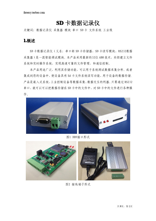
SD 卡数据记录仪
关键词:数据记录仪 采集器 模块 串口 SD 卡 文件系统 工业级
1.概述
SD 卡数据记录仪(又名:串口转 SD 卡存储器,SD 卡读写模块、RS232数据 采集器)是一款智能调试模块。本产品采用最新的32位 ARM 技术,内部建立文件 系统和实时操作系统,实现高速可靠的文件管理,和通信控制。
注意: 1,最多支持 3 个文件句柄同时操作,即同时打开了 3 个文件读写。文件句柄 2 默认为串口 直接存储数据的文件,因此,如果需要使用串口数据直接保存,请勿操作文件句柄 2。 2,如果需要读写的文件超过 3 个,可以使用同一个文件句柄,打开一个文件读写后,关闭 该文件;然后,再打开下一个文件操作。
【4,读文件】功能码: 0X30|FileIndex
发送到记录仪串口:'S'+Num+'0X30|FileIndex'+ReadDataNum+FA+'E' 从记录仪返回: 操作成功: 'S'+Num+'0X30'+'1'+"DATA"+FA+'E' 操作失败: 'S'+Num+'0X30'+'0'+FA+'E' 注意:ReadDataNum 为一个字节长度。
共 9页,第 6页
【6,创建文件夹】功能码 0X50
发送到模块串口:'S'+Num+0X50+"dirname"+FA+'E' 从模块返回: 操作成功: 'S'+Num+0X50+'1'+FA+'E' 操作失败: 'S'+Num+0X50+'0'+FA+'E' 例如:创建文件夹“AA”:'S'+0X03+0X50+'A'+'A'+'0'+'E' HEX: 53 03 50 41 41 30 45
MBUS集中器说明书
M-BUS集中器说明书1 概述集中器带有M-BUS、RS232,RS485 接口分别与M-Bus 仪表和抄表主站或控制器连接。
与M-BUS 仪表的通讯,采用消费类仪表国际标准M-BUS(Meter-BUS,EN1434-3),按照树型总线连接。
2 型号介绍集中器型号包括HS1101,HS1101B,HS1102A 和HS1106B 四种种型号。
2.1 HS1101A 型为单路无通讯协议转换型,该型号提供M-BUS 接口和RS232 或RS485 接口,只支持数据透传,直接通过RS232 或RS485接口发送读表指令。
最大连接仪表数量为60 块。
2.2 HS1101B 型为单路支持标准MODBUS 协议型,用户可发送标准MODBUS 协议指令读取仪表数据。
最大连接仪表数量为60 块。
2.3 HS1102A 型为多路(最大6 路)无通讯协议转换型,提供可选的1至6路,最大连接仪表数量为360 块。
2.4 HS1102B 型为多路(最大6 路)支持标准MODBUS 协议型,用户可发送标准MODBUS 协议指令读取仪表数据。
最大支持仪表数量360 块。
3 性能指标3.1 工作电压:12V 1A DC。
3.2 通讯接口:RS232/RS485 接口,M-BUS 接口。
3.3 该集中器提供单路或多路M-BUS 接口,单个集中器最多支持6 路,每路可连接60 块仪表。
3.4 指示灯包括电源指示,收发状态指示,过载报警指示。
3.5 工作环境:温度:-30℃---80℃湿度:90%,无结晶。
4 功能特点4.1 集中器带有M-BUS、RS232,RS485接口分别与M-Bus仪表和抄表主站或控制器连接4.2 单个集中器最多可连接M-BUS仪表360台(六路通道,每路接表60台)4.3 热量表与集中器的通讯连接,采用消费类仪表国际标准M-BUS(Meter-BUS,EN1434-3),按照树型总线连接4.4 采用普通的两芯电缆连接,同时完成数据通讯和提供通讯电源的功能,最大传输距离可达1000 米。
mSIS_3030(31)说明书
M-Bus<>Modbus转换器mSIS-3030(31)产品说明书V1.1概述北京同州铭远科技有限公司专注于工业/民用智能控制领域,掌握大量电子自控领域的核心技术,是集创新研发、产品生产和工程服务为一体的全面的创新技术型公司。
我们竭诚为客户提供最具竞争力的优质、高效、便捷的产品和服务。
Meter-Bus (M-Bus),又称仪表总线,是一种专门为消耗类测量仪表传送信息而设计的优质总线,在建筑物和工业能源消耗数据采集方面有着广泛的应用。
M-Bus只需使用一对无极性传输线,就可以在传输串行数据的同时向总线设备提供电源;而且其电压/电流调制的方式极大提高了总线的抗干扰能力。
使用M-Bus 可大大简化建筑物能耗智能化管理系统的布线和连接,具有结构简单、造价低廉、可靠性高的特点。
M-Bus最先在欧洲标准化,主要遵循EN1434/EN 13757,中国标准CJ-T188-2004。
(了解更多M-Bus 信息,请访问)Modbus,是全球第一个真正用于工业现场的总线协议,目前已经成为通用的工业标准,国际上由Modbus-IDA维护,中国标准为GB/T19582-2008。
mSIS-3030,是北京同州铭远科技有限公司推出的M-Bus与Modbus(RTU)之间高性能的协议转换器。
使用mSIS-3030,用户可以通过标准的3线RS-232串口或者两线制RS-485接口,采用成熟的Modbus协议,以读取寄存器的方式直接获得连接在M-Bus上的仪表的采集数据。
mSIS-3030同时实现了物理层和协议层的转换功能;其内置隔离电路,能够有效保护连接串口的设备;其在M-Bus端进行了多重保护和滤波处理,能够提供稳定、本质安全和抗干扰能力极强的M-Bus通信;在数以千计的工程实践和实际使用中得到广泛的好评。
mSIS-3030支持所有进口表的解码和绝大多数国产表的数据协议,对于较为特殊的协议,只需要进行略微修改即可完美应用。
USB串口转换器(Micro USB B类)2014.02 Rev. 1.01 产品说明书
USB Serial Converter (Micro USB B type)2014.02Rev. 1.01Contents1.Introduction (2)1-1. Overview (2)1-2. Package Contents (2)1-3. System Requirements and Restrictions (2)1-4. RS-232C connector Pin Assignment (3)2.Installation and Operation on Android OS (4)2-1. Installation of USB60Term application (4)2-2. How to operate USB60Term (5)3. Specifications (8)*All trademarks and logos are the properties of their respective holders. *The specifications and pictures are subject to change without notice.11.Introduction1-1. Overview● REX-USB60MB is a USB to serialconverter. Compatible with UniversalSerial Bus specifications Rev. 1.1.● Up to 230.4Kbps data transfer rate.●Micro USB (B type Male)Easy to connect Android tablet or smartphone.●Power/Transmit/Receive LED indicatorsfor monitoring communication status.1-2. Package ContentsThis product is shipped with the following items:● REX-USB60MB USB Serial Converter● Warranty Card in JapaneseNote: Not include the printed document of User’s manual and Software CD. 1-3. System Requirements and RestrictionsHost machine●Android tablet/smart phone with free Micro USB B type portOperating System● Android OS 3.2、Android OS 4.0 or laterNote:The Android driver software for this product is not provided from RATOC Systems, Inc.The FTDI Java D2xx for Android Library which is provided by FTDI Ltd, “D2xx.jar” works with this product.And we made the terminal application “USB60Term” using “D2xx.jar”, published at Google Play.21-4. RS-232C connector Pin AssignmentThe pin assignment of the connector is below:This DB9pin connector is compatible with ANSI/EIA/TIA-574 specifications.1 2 3 4 5Signal NameDirectionDTE – DCE. Meaning1 DCD <--- Data Carrier Detected2 RXD <--- ReceivedData3 TXD ---> TransmittedData4 DTR ---> Data Terminal Ready5 GND - SignalGround6 DSR <--- DataSetReady7 RTS ---> Request to Send8 CTS <--- Clear to Send9 RI <--- RingIndicator6 7 8 932. Installation and Operation on Android OS Please make sure that the Android tablet meets the following specifications: •USB port is Micro-USB B or AB•Android OS version is 3.2, 4.0 or later•USB Host mode is available2-1. Installation of USB60Term applicationDownload the terminal application “USB60Term” from Google Play.1) Start Google Play. Type “USB60” to the search box on Google Play.2) Select “USB60Term” from the search result, and install it.3) After USB60Term application is installed, connect USB Serial Converter. Then, the below window will show:Set the check to the checkbox “[ ] Useby default for this USB device”.If you set the uncheck to the abovecheckbox, the above popup windowshows up at each time attaching USBserial converter.4) Select “OK”, and then start USB60Term. The below window will show:After the USB Serial Converter is recognized, the “Connected” message shows up on the left of “USB Serial”. And then, it will be ready for use.42-2. How to operate USB60TermWhen the USB60Term starts, the below window will show:1Status of detecting USBSerial Converter Display the status of detecting USB SerialConverter, this status shows “Connected” or “Not connected”.2 “To setting” buttonThe button for changing serial parameter.After changing the parameter values, tap the“Configure” button to enable new values.3 Send data fieldAfter tapping this field, enter the send data.4 Receive data fieldDisplay the received data.The displayed data is holding till the “Clear ”buttonis tapped.5 Option menuOption menu shows up6 “Send” buttonTransmit the data of the “send data field “ 7 “Send with CR+LF” buttonTransmit the send data with CR code(0x0D) and LF code(0x0A) 8“new line [CR+LF]” checkbox Before transmitting the send data, an LF(0x0A)code in the send data will be replaced with the CR+LF(0x0D+0x0A) code.9 “Clear” buttonErase the data of the “Receive data field ” Option menuRTS_clear checkboxWhen checked the “RTS_clear” checkbox, then the RTS signal will be stable to clear (off). If unchecked this checkbox, the RTS signal will be unstable after opening serial port.5How to send dataWhen tapping the send data field, the software keyboard shows up. Then, enter the send data.You can set multiple lines with a new-line.After entering the send data, tap the “Send” button or the “Send with CR+LF” button at the upper-right of screen. Then, the send data will be transmitted.How to receive dataThe data from USB Serial Converter will be always received.And the received data will show at the “receive data field”.When tapping the “Clear” button, the data of the “Receive data field” will be erased.6How to change serial parameterAfter tapping the “To setting” button, you can change serial parameter values. When edit is ready, the “To setting” button will be changed to the “Configure” button. And the back-ground color of serial parameter values will be changed in light blue.Baud Rate Stop Bit Data Bit Parity Flow ControlAfter finishing editing the parameter values, tap the “Configure ” button for changing values.73. SpecificationsProduct Name REX-USB60MBSerial Input/Output level RS-232C levelUSB Specification USB(Universal Serial Bus) Specifications Rev. 1.1 Connector USB :Micro-USB B maleRS-232C:D-Sub9 male (with anchor [#4-40]) Number of I/O ports 1 portUnit Dimensions 3.35[L] x 1.1[W] x 0.43[H] in (85[L] x 28[W] x 11[H] mm) Cable Length Approx. 2.83 ft (85 cm)Weight 0.194 oz (55 g)Data transfer mode Asynchronous (Start stop synchronization)Data transfer Rate (Baud) 300/600/1,200/2,400/4,800/9,600/19,200/38,40057,600/115,200/230,400 bpsTransmit Distance Within 50ft (15m)Power Voltage DC+5V (Powered for USB Bus)Power Consumption Average: 36mA(5V) Max.: 60mA(5V)Serial Parameter Data bit: 7/8 Start bit:1 Stop bit: 1/2Parity bit: even/odd/noneRS-232C connector D-SUB9PIN RS-232C connector MaleANSI/EIA/TIA-574LED Indicators PWR:Power LEDIf 5V power from USB bus is properlysupplied from USB bus, this indicator LEDwill be on.TXD:Transmit data indicator (Host to Device)RXD:Receive data indicator (Device to Host) Operating Environment Temperature: 32ºF to 122ºF (0ºC to 50ºC)Humidity: 10 to 90% (non condensing)Storage Environment Temperature: -4ºF to 149ºF (-20ºC to 65ºC)Humidity: 10 to 90% (non condensing)Note:1.Do not remove while the application is communicating. System will beunstable.2.Do not operate to suspend while the application is communicating.System will be unable to resume properly.3.This product does not support the serial mouse for connecting to RS-232Cport.89。
迅饶Mbus集中器使用说明
迅饶Mbus集中器使用说明
一、Mbus 介绍
M-Bus 远程抄表系统(symphonic mbus)是欧洲标准的2 线的二总线,主要用于消耗测量仪器,诸如热表和水表,流量计系列。
Mbus 总线是欧洲标准,与普通485 总线主要区别在于:
1,Mbus 两线没有正负之分(无极性),而485 总线是有正负极性之分;
2,Mbus 总线工作是有30~36V 工作电压,用于仪表传输数据;485 总线一般工作电压是3.8V 左右;
3,Mbus 可以完全支持星型连接方式总线,485 总线常规都是需要手拉手串联方式;
二、Mbus 集中器工作原理
迅饶Mbus 集中器通过Mbus 接口连接到仪表Mbus 总线,然后转换为
RS485/RS232 电平方式,这样可以让PC 上位机或者串口设备访问终端仪表。
三、接线图
Mbus-RS485 转换模块,提供Mbus 总线至RS485 总线转换服务;
●供电:DC12V~24V
● Mbus 接线:5 组Mbus 总线Mbus+,Mbus-(每组不超过32 台设备)
●通信口:隔离RS485 通信的A+B-信号线。
- 1、下载文档前请自行甄别文档内容的完整性,平台不提供额外的编辑、内容补充、找答案等附加服务。
- 2、"仅部分预览"的文档,不可在线预览部分如存在完整性等问题,可反馈申请退款(可完整预览的文档不适用该条件!)。
- 3、如文档侵犯您的权益,请联系客服反馈,我们会尽快为您处理(人工客服工作时间:9:00-18:30)。
M-BUS转串口(RS232/RS485)模块mSIS-1030产品说明书V1.2
mSIS-1030概述
为了便于连接符合EN1434、EN13757等标准的总线设备,我公司研发了mSIS-1030 设备,该设备支持符合欧盟标准的M-BUS 协议设备的转换。
通过mSIS-1030,M-BUS 电平转换为RS232/RS485 电平,PC 机或其它设备可以通过串口直接访问M-BUS设备(数量多达250个)。
mSIS-1030实物图如下:
图1 mSIS-1030实物图
mSIS-1030技术说明
⏹采用冗余设计方式,稳定工作范围宽
⏹输出短路、过载保护,输入保护设计,更安全可靠
⏹供电:220±20%VAC
⏹外壳:高硬度铝壳,安装附件
⏹工作温度:-20℃~70℃
⏹存储温度:-40℃~125℃
⏹工作湿度:5%~95%,无凝露
⏹通信速率:300bps~9600bps,流控自适应
⏹负载能力:250
⏹指示灯:电源PWR、过载短路SHORT、数据通信RXD
⏹外形尺寸(mm):230*180*50
⏹串口方式:RS232/RS485
⏹支持所有进口热表解码;提供国产表解码支持
⏹上位机软件免费提供
mSIS-1030 使用说明
接线图示:
符合M-BUS 物理层协议的热表、水表、燃气表。
M-BUS
从站
图 2 mSIS-1030 与PC 连接的应用示意图
图 3 mSIS-1030 模块电源接线图
图4 mSIS-1030 与设备硬件连线
使用情况:
1、刚上电时,PWR和RXD灯亮,显示绿色;大概10s后,RXD灯熄灭。
PWR和RXD
灯亮,说明电源供电正常;之后RXD灯熄灭,说明初始化完成,可以正常使用。
上电时若SHORT灯亮,说明M+/M-短路或者负载超过最大限制(250),应该检查M+/M-接线。
2、在通讯过程中,RXD灯不断闪烁,说明上位机在读设备的数据,读数完毕后,RXD
灯熄灭。
3、如果模块过载,SHORT灯亮,此时需要断电一段时间,减小负载后,再给模块重新
上电才能正常通讯。
4、M-BUS 的传输距离可达1km-2km,与挂接仪表的波特率有关,波特率越低传输距
离越远,如果要传输2km,必须把波特率设置成300bps。
M-BUS 标准要求,传输线阻必须小于90 欧姆,否则对模块的负载能力有影响。
5、信号M+和M-不能短路,短路后需要断电、重新上电后,模块才能恢复正常工作状
态,正常工作时M+、M-之间的输出电压应该在31V左右,读数据时该值会略微上升。
6、PE端子,一般悬空,但是在现场干扰严重的情况下,需接可靠大地。
7、mSIS-1030能够承受长时间的M+/M-之间的短路,只要将短路故障排除,数秒之内模
块即可恢复正常工作。
8、RS232//RS485接口可以通过跳线切换。
RS485接口自带各种保护,传输距离1km。
M-BUS配置软件使用说明
为了方便MBUS相关模块的使用和测试,我公司开发出功能强大的M-BUS配置软件,其界面如下所示:
图5 M-BUS配置软件
1.介绍“单表查询”功能,此功能用于测试热表和转换模块。
【第一步】在“工作模式”栏目中,选择“MBUS测试”;在“串口配置”栏目中选择连接mSIS-1030的串口号,而后点击“打开串口”。
如下图所示:
图6 选择模式和设置串口
【第二步】选择“单表查询”属性页,并在“仪表设置”栏目中,选择和输入M-BUS 总线上设备的地址。
选择“默认”,程序将主动尝试使用万能读表指令进行通信。
也可填入实际的热表一级地址(16进制)和二级地址等。
之后点击“开始发送”按钮。
如下图所示:
图7 设置仪表地址和开始读数
【第三步】等待约1s之后,返回结果如下图,在“返回”栏中显示热表的数据(16进制),在“提示”栏中显示解码的数据。
我们可提供遵循EN13757-3协议的热表(进口表)的解码DLL文件和编程参考!
图8 返回数据和数据解码
2.介绍“总线搜索”,此功能通过扫描MBUS总线上的设备来获得数据和参数,在实际应用场合非常有效。
【第一步】在“工作模式”栏目中,选择“MBUS测试”;在“串口配置”栏目中选择连接mSIS-1030的串口号,而后点击“打开串口”。
如下图所示:
图9 设置工作模式和串口
【第二步】选择“总线搜索”属性页,并在“进口表一级地址”栏目中,选择和输入M-BUS总线上设备的地址范围(1~250)。
之后点击“搜索”按钮。
如下图所示:
图10 设置仪表地址范围和开始扫描
【第三步】程序开始自动扫描MBUS总线上的设备,进度条走完,表明搜索结束。
搜索到的热表地址将展现在上方的“热表地址”栏中,单击热表地址,在下方的“提示”栏目中将显示其完整的设备信息和当前数据。
如下图所示:
图11 扫描结果显示和数据解码
【第四步】如果需要保存总线搜索的结果,可以单击“导出”按钮,按照弹出的提示框操作,非常方便。
图12 导出扫描结果
附录:
一般M-BUS 设备的串口参数设置为波特率2400,8 为数据位,1 为停止位,偶校验,十六进制码制。
1、进口表读表命令:105BFE5916,其中FE 是万能地址,回复的是一串数据,字节数可
能不同。
2、国产表指令不一。
3、M-BUS总线的电平特性如下:
发送:传号电压:24V~36V(CJ-T188-2004:20.8V~42V)
空号电压:传号电压-12V(CJ-T188-2004:传号电压-10V)
接收:传号电流:≤1.5mA
空号电流:11~20mA
更多信息请访问。