tunkers气缸
长春市宣嘉和机械自动化有限公司_企业报告(供应商版)

4 / 15
9 地车充电器维修采购
一汽模具制造有限公司
\
2022-09-05
10 TUNKERS 气缸
一汽模具制造有限公司
\
2023-01-05
*按近 1 年项目金额排序,最多展示前 10 记录。
(2)天津(6)
序号
项目名称
1 AUDIT 检测台
招标单位
中标金额 (万元)
一汽模具(天津)有限公司
15.6
本报告于 2023 年 02 月 21 日 生成
2 / 15
1.3.2 重点项目 重点项目
项目名称
TOP1 AUDIT 检测台
招标单位
一汽模具(天津)有 限公司
中标金额 (万元)
15.6
TOP2
小车变频控制柜及小车变频调压系 一汽模具制造有限公
统
司
\
TOP3 水冷机维修组件 10.28
一汽模具制造有限公 司
\
TOP10 西门子备件
一汽模具制造有限公 司
\
公告时间 2022-12-30 2023-02-09 2023-01-13 2022-10-12 2022-11-21 2022-12-23 2022-10-17 2022-10-17 2022-10-31 2022-09-02
*项目金额排序,最多展示前 10 记录。
分地区主要项目
(1)吉林(26)
序号
项目名称
招标单位
1
小车变频控制柜及小车变频调压系 统
一汽模具制造有限公司
2 水冷机维修组件 10.28
一汽模具制造有限公司
3 钢构螺栓
一汽模具制造有限公司
4 甩油盘(带密封圈)
TUNKERS 汽缸型号表
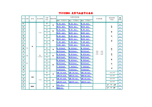
控制参数
其它参数
备 注
□ □ □ □ □ □
单 杆 伸 缩 缸 SZK
Z (气/手动)
40 63 40 40
M (手动)
...T00 —无控 ...T08 —气控 ...T12 —电控
□ □ □ □ □ □
09 10 11 12
双 杆 伸 缩 缸 SZV
63
M (手动) D Z (双导杆) (气/手动)
控制参数
扬角参数 (优选)
2D 图册
□
竖 横 竖 横 竖 横 竖 夹 横 竖 紧 横
Z (气/手动)
K2:…45°,90°,105°
□ □ □ □ □ □ □ □ □ □ □ □ □ □ □
...T00… —无控 ...T08… —气控 ...T12… —电控
竖 横
缸
竖 横 竖 横 竖 横 竖 横
°; K:…4型参数 A10(夹臂居中) A11(夹臂偏右) A12(夹臂偏左) K 50 A11 ... K2 50 A11 ... K 63 A11 ... K2 63 A11 ... K 80 A11 ... K2 80 A11 ... V 80 A11 ... V2 80 A11 ... K 50 Z A11 ... K2 50 Z A11 ... K 63 Z A11 ... K2 63 Z A11 ... K 80 Z A11 ... K2 80 Z A11 ... V 80 Z A11 ... V2 80 Z A11 ... MK 50.1 A11 ... MK2 50.1 A11 ... MK 63.1 A11 ... MK2 63.1 A11 ... K 50 A12 ... K2 50 A12 ... K 63 A12 ... K2 63 A12 ... K 80 A12 ... K2 80 A12 ... V 80 A12 ... V2 80 A12 ... K 50 Z A12 ... K2 50 Z A12 ... K 63 Z A12 ... K2 63 Z A12 ... K 80 Z A12 ... K2 80 Z A12 ... V 80 Z A12 ... V2 80 Z A12 ... MK 50.1 A12 ... MK2 50.1 A12 ... MK 63.1 A12 ... MK2 63.1 A12 ... -
抓具技术总结
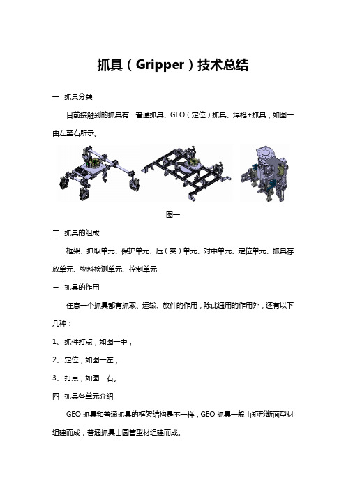
抓具(Gripper)技术总结一抓具分类目前接触到的抓具有:普通抓具、GEO(定位)抓具、焊枪+抓具,如图一由左至右所示。
图一二抓具的组成框架、抓取单元、保护单元、压(夹)单元、对中单元、定位单元、抓具存放单元、物料检测单元、控制单元三抓具的作用任意一个抓具都有抓取、运输、放件的作用,除此通用的作用外,还有以下几种:1、抓件打点,如图一中;2、定位,如图一左;3、打点,如图一右。
四抓具各单元介绍GEO抓具和普通抓具的框架结构是不一样,GEO抓具一般由矩形断面型材组建而成,普通抓具由圆管型材组建而成。
1.抓具框架分为一般抓具和GEO抓具1.1GEO抓具框架框架一般由铝合金型材组成,GEO(定位)抓具的框架由矩形断面型材构成,如图二,目前使用的矩形断面型材一般是80×40的断面。
一般在框架上有:阀岛或阀安装板、机器人连接板或在需要抓具互换的情况下有换枪机构(换枪盘)安装板、物料感知单元和抓具存放单元。
如图二所示。
图二1.1.1定位抓具的连接块(标准件)此种连接块为标准件,但非国标件,有厂家提供,如MISUMI。
如图二所示,由左至右分别为90°、135°和45°。
图三1.1.2定位抓具的连接板(外协件)此种连接板由设计者根据需要设计形状。
如图三所示,由左至右分别是90°转弯的L连接板、T字型连接板、十字连接板。
图示三种为比较常用和形状较为规则的。
图五所示为不规则连接板。
此种件的厚度一般为8mm。
此种板的设计原则是:与任意一根型材连接时有两个直径为8mm的销孔和直径为9mm的螺钉过孔。
图四图五1.2普通抓具框架普通抓具的型材由圆管型材构成,如图五,目前使用的主要有两种规格:直径为40和60。
采用不同规格的型材时,使用的型材之间连接块(Joint)是不一样的。
一般在框架上有阀岛或阀安装板、机器人连接板或在需要抓具互换的情况下有换枪机构(换枪盘)安装板。
如图六所示。
气缸与磁性开关知识总结
当从无杆腔输入压缩空气时,有杆腔排气,气缸两腔的压力差作用在活塞上所形成 的力克服阻力负载推动活塞运动,使活塞杆伸出;当有杆腔进气,无杆腔排气时,使活 塞杆缩回。若有杆腔和无杆腔交替进气和排气,活塞实现往复直线运动。
1
2
14
3
4
5
6
13 12 11 10 9 8 7
1、3-缓冲柱塞;2-活塞;4-缸筒;5-导向套 ;6-防尘圈;7-前端盖 ;8- 气口 ;9-传感器;10-活塞杆;11-耐磨环;12-密封圈 ;13-后端盖;14-缓冲 节流阀
气缸的原理 ........................................................................................................................ 3 普通气缸 .................................................................................................................... 3 磁性开关气缸的结构和工作原理.....................................................................动作指示灯 ;2-保护电路 ;3-开关外壳;4-导线;5-活塞;6-磁环;7 -缸筒;8-舌簧开关
朗克公司气缸系列产品指南说明书

The Right Cylinder for the Right DutyContentsIntroduction (2)Hydraulic vs. Pneumatic (2)Design Factors (2)Capacity (3)Stroking Distance (3)Speed (3)Temperature (3)Mounting Styles (4)Cylinder Bore Size (4)Piston Rod Size (4)Cylinder Configurations (5)Rod Ends / Rod Threading (5)Cylinder Body Tube (5)Stop Tubing (5)Seals (5)Additional Considerations (5)Conclusion ..................................................................................................6About the AuthorsJim Hauser is a Senior Engineer who started his career as an Engineer Trainee at Parker Hannifin Cylinder Division 43 years ago. Throughouthis tenure, he has held positions as a Design Engineer, Lab Supervisor and most recently Quote Engineering. He has a BS in Mechanical Engineering from the Illinois Institute of Technology. Rade Knezevic has 24 years with Parker Hannifin and is currently a Global Account Manager. He holds a BSin Industrial Engineering, from the University of Illinois Urbana-Champaign and an MBA from Keller Graduate School of Management. Rade is responsible for the sales growth of Industrial and Mobile cylinders in the Eastern Region of the US, which includes management of six field-based Cylinder Application Engineers (CAEs). Rade started his career in Manufactur-ing Engineering as a Trainee and has held positions as a CAE, Product Manager and Division Business Development Manager.Jim Hauser Rade Knezevic Senior Engineer, Division Sales Manager, Parker Cylinder Division Parker Cylinder DivisionIntroductionThe first hydraulic press may have been invented in the 3rd Century BC, but the fluid power universe has become a little more compli-cated since then. Today’s hydraulic cylinders, which essentially convert fluid pressure and flow into force and linear movement, are complex devices incorporating a wide range of individual components available in a multitude of dimensions, configurations and materials. For many OEM design engineers, playing it safe by over-engineering cylinder specifications has become a precautionary habit in the presence of ever-improving cylinder technologies. This article will help clarify why less is sometimes more when it comes to complex hydraulic systems, while identifying some of the many factors to be considered when specifying hydraulic cylinders.Design Factors in Hydraulic Cylinder SpecificationSpecifying hydraulic cylindersis essentially a balancing act as each design factor influences one or more of the many other design considerations. For example, the urethane seals ideal for applications as cold as -65°F (-54°C) will tolerate 200°F (129°C) of heat, while other materials capable of tolerating temperatures as high as 500°F (260°C), will do so at the sacri-fice of some cold-temperature performance.Although NFPA standards and ISO-compliant guidelines are a great starting point for hydraulic system design, many industries have guidelines of their own. Working with an engineering manufacturer experienced with all these standards can expedite the design process.Cylinder manufacturers can offera range of options capable ofachieving the widest scope ofperformance requirements thatincrease the likelihood thatstandard components will meetthe design criteria of a application.For example, most cylinder man-ufacturers offer 19 mount options,which cover the standard NFPAmount offerings. Standard compo-nents have the additionaladvantage of being readilyavailable worldwide, expeditingjust-in-time warehousing anddelivery of replacement parts ascomponents reach the end oftheir service life cycle.A review of the major factors is tobe considered when specifyinghydraulic cylinders follows.Hydraulic vs. PneumaticAlthough pneumatic systems are in some respects simpler, they are generally incapable of achieving the transfer of higher loads and forces. Hydraulic cylin-ders also have the advantage of smoother, more controllable movement as they are devoid of the spring-like action associated with the release of gaseous fluid media. As an added benefit, hydraulic systems can perform ancillary functions such as lubricating and cooling.However, since the availability ofpower and media is a non-nego-tiable factor in fluid powersystem design, it should benoted that a properly designedand sized pneumatic system canachieve higher performancewhere a compact footprint is notrequired. Further considerationsof pneumatic cylinder design areoutside the scope of this article.Although NFPA standards and ISO-compliant guidelines are a great starting point for hydraulic system design,many industries have guidelines of their own. “”CapacityMedium-duty systems account for most of industrial applications and are typically at 1000 PSI. Heavy-duty systems are com-mon to applications such as hydraulic presses, automotive applications, and other related industrial applications. Standard heavy-duty hydraulic cylindersare capable of handling pres-sures as high as 3000 PSI, withload capabilities relative to thefull piston area (in square inches)when exposed to fluid pressuremultiplied by the gauge pressurein PSI. Excessive load require-ments may be achieved withoutsacrificing other areas of perfor-mance through the use oftandem cylinder constructionsrather than larger bore or customhigh-pressure cylinder designs.Stroking Distance RequirementsAlthough custom stroke distanc-es above 10 feet (3.05m) are possible. Pressure rating can be a concern. Rod diameter needs to be determined to handle the load. If necessary, a pressurerating on load in thrust (pushmode) will need to be specified.Rod sag from horizontal applica-tions may result in premature rodbearing wear. Weighing eachpositive effect against potentialnegatives is essential to optimiz-ing hydraulic systemperformance.SpeedEvery application engineer has his or her own definition of “excessive speed.” As a good rule of thumb, standard hydraulic cylinder seals can easily handle speeds up to 3.28 feet (1 meter) per second. The tolerance threshold for standard cushions is roughly two thirds (2/3) of that speed. Frequently, a standard low-fric-tion seal is the better choice forhigher speed applications. Buthere too, what you gain in oneaspect of performance you losein another. The greater the fluidvelocity, the higher the fluidtemperature, so when opting forspeed-increasing customizationsit is essential to consider theimpact of higher temperatures onthe entire hydraulic system. Insome hydraulic systems, over-sized the ports may eliminateescalated temperature concerns.TemperatureAs previously noted, hydraulic cylinder systems using standard components can be designed to meet application temperatures as hot as 500°F (260°C) and as cold as -65°F (-54°C). But tempera-tures affect both the “hard” and “soft” design components of cylinders. Applications requiringtemperature extremes at eitheror both ends of the temperaturespectrum require extensiveknowledge of the interdependen-cy of individual components toachieve the best balance ofshort- and long-termperformance expectations. Forexample, applications near thenorth or south poles, will seecontraction of the seals andmetal parts due to the extremetemperatures.Mounting StylesThere are fundamentally three categories of mounting styles. Both Fixed and Pivot styles can absorb forces on the cylinder’s centerline and typically include medium- and heavy-duty mounts for accommodating thrust or tension. A third category of Fixed styles allows the entire cylinder to be supported by the mounting surface below cylinder centerline, rather than absorbing forces only along the centerline.There are several available standardized mounts within these categories. Engineers can use these variety of mount offerings for an ever-widening number of application require-ments. NFPA Tie rod cylinders, which are used in the majority of industrial systems, typically can be mounted using a variety of standard mating configurations from trunnion-style heads and caps to extended tie rod cap and/ or head end styles, flange-style heads, side-lug and side-tapped styles, a range of spherical bearing configurations, and cap fixed clevis designs. Most of these mounting options are available for both single acting and double rod cylinders.The goal of every mounting design is to allow the mount to absorb force, stabilizing the system and optimizing perfor-mance. For rods loaded primarilyin compression (push), cap endmounts are recommended; forthose in tension (pull), a headend mount is preferred.It is the amount of tension orcompression that determinespiston rod diameter; it is theamount of pull or push thatdetermines the bore diameter.Other relevant factors to considerwhen selecting a mounting styleinclude:• Load• Speed• Cylinder motion (straight/fixed or pivot)Every mounting type comes withits own benefits and limitations.For example, trunnions forpivot-mounted cylinders areincompatible with self-aligningbearings where the small bearingarea is positioned at a distancefrom the trunnions and cylinderheads. Improper use of such aconfiguration introduces bendingforces that can overstress thetrunnion pins.Many performance expectationsthat at first appear to requireatypical mounts can be accom-modated by existing styles,sometimes with only slightmodifications, facilitating replace-ment and reducing costs.Cylinder Bore SizeBore size is related to operating pressure; as previously noted, it is the amount of push or pull force required that determines the bore size needed. Earlier generations of steel and alumi-num mill equipment oftenrequired the use of non-standardbore and rod sizes. Today,virtually every industrial require-ment can be met with NFPAstandard and/or ISO-compliantcomponents.Style J(NFPA MF1)Style JB(NFPA MF5)Style H(NFPA MF2)Piston Rod Size OEM design engineers probablyrequest customization of piston rod sizes more frequently than any other hydraulic cylinder component. What is not always considered is the simple fact that push or pull is never independent of stroke length. Just as a pushed rope holds a straight line only in relation to its length (the longer the rope, the more the rope curls), piston rods under compression or tension tend to diffuse force in non-linear directions.Specifying costly materials such as stainless steel or alloy steels for the rods themselves is another common example of over-engi-neering. In most extreme applications, chrome plating provides a high level of corrosion-resistance required to optimize system longevity.Cylinder ConfigurationsFor applications requiring equal force pressure on both sides of the piston, a standard double-acting cylinder configuration using pressure to extend and retract the cylinder, combined with a four-way directional control valve to direct pressure to either the head or the end cap, is almost always preferable to more customized solutions. An experienced hydraulic solu-tions manufacturer will be familiar with every conceivable cylinder assembly configuration and the unintended consequences of customizing individual components versus combining standard cylinders in creative ways to meet unusual performance requirements.Rod Ends / RodThreadingThis is one area where standardoptions are so vast customizationis rarely needed. Additionally,standard threads can be made ininch or metric format. Typically,each available diameter isavailable in four distinct rod endstyles. Even in those rareinstances where a modificationseems to be called for, it isimportant to considerthe effects of modifications onfunction-enhancing accessories.The relatively small performancecompromise resulting fromstandardizing rod ends is almostalways warranted by the versatil-ity such standardization affords.Even a modest modificationsuch as under-sizing threads willrequire de-rating the cylinder andmay necessitate special toolingfor non-standard pitch, resultingin delays, expense, and theinability to readily mate withaccessory components.CylinderBody TubeStandard cylinder bodies areplain steel or chromed plated andwill be able to handle a majorityof applications. Using alloysteels, stainless steel or brassmaterials are prevalent in specialapplication like a water typeenvironment.Stop TubingStop tubing is generally used tolengthen the distance betweenthe rod bearing and the pistonbearing in order to reducebearing load on push-strokecylinders when the cylinder isfully extended. Stop tubing isespecially critical for horizontallymounted cylinders where it helpsto restrict the extended positionof the rod. In such applications,increased distance helps achievegreater stability and increasebearing life.SealsAlthough it is not common torequire all existing materialcompounds, an experiencedhydraulic system manufacturerwill offer seals to meet a com-plete range of temperatures andfluid types, and can help guidean engineer’s specification tomeet precise application require-ments.HY08-1731-B1 07/20© 2020 Parker Hannifin Corporation Parker Hannifin CorporationCylinder Division500 South Wolf RoadDes Plaines, IL 60016-3198 USA /cylinder ConclusionThere are certainly applications for which specifying the right cylinder for the right duty require some customization either in component size, material type or configuration. However, far more often than not, partnering with an experienced hydraulic system solution manufacturer early in the design process will save the OEM engineering team time and money while ensuring the system does its assigned duties as efficiently as possible for as long as possible.Additional Considerations Every industrial application is unique, and there are many ancillary components involved in hydraulic cylinder specification. Energy-absorbing cushions, pillow blocks, regenerative circuits, over- or under-sizing ports — all these and more contribute to optimizing the performance of hydraulic sys -tems, depending on each application’s specific perfor -mance requirements. As with the specification of more fundamental components, selecting appropriate ancillary components can present a specification challenge. For example, cushions are intended to retard the force of motion, but OEM engineers sometimes overlook the fact that fluids are typically not moving very fast anyway and may not require such redundancy in certain types of systems. An engineer may be tempted to take a “belt and suspenders” approach to design -ing push/pull systems by using cushions with spring cylinder systems, overlooking the fact that the oil needs to work its way through the cap, hoses, valves and so on. In such cases, specifying standard single action cylinders with cushions may be wiser than attempting to insert cushions into spring cylinders.New Automated Cylinder Quoting ToolNeed help determining the right cylinder for yourneeds? Use Parker’s easy to use cylinder quoting tool.。
TUENKERS 抓手概述

各种与定位销,吸盘, 传感器等部件连接的 结构
Double Traverse
吸盘
定位销
NC块
传感器
TÜNKERS® 抓手产品介绍
圆管系统连接件
主框架部件 - GF - GFLA - GK - GNFA - GNK - GNKS - GNXK - GRW - GR - GRST - GTS - GT
TÜNKERS® 抓手产品介绍
碳素管的特点
重量更轻 偏移更小 精度更高 震动更小 所需维护更少 所需机器人投入更少
TÜNKERS® 抓手产品介绍
欧标八角管
TÜNKERS® 抓手产品介绍
欧标八角管抓手由欧洲欧标管研究小组开发。(现有成员: Audi, BMW, Daimler, Porsche, Volkswagen) Tünkers被授权允许进行制造及装配。
China
E89 C344 SK 356 E84 SK 462 SK 25x Dodge PL6 F10/F11 X62 VW 469 Changchun W204 PL6
Anbauteile
Unterbau / Hinterbau (Eurogreifer) Boden / Klappen / Seitenwand / Anbauteile Seitenwand / Boden Klappen / Anbauteile (Eurogreifer) Erweiterung Längsträger / Radhaus Carbongreifer für kritische Greifer SA / SWA (Eurogreifer) Längsträger Stückzahlerweiterung (Rundrohr) Stückzahlerweiterung (Rundrohr) Klappen
神龙焊装夹具设计技术要求(标准)

文献分类号:XXX 备案号:XXXXXX 焊接工装夹具设计技术要求(征求意见稿)****—**—**发布 ****—**—**实施Q/DPCA神龙汽车有限公司企业标准神龙汽车有限公司 发布(标准密级)签 字编制审核标准化批准许泽军DUWH/STG (姓名)(部门)(姓名)(部门)(姓名)(部门)日期2008年10月10日)(签字)日期(签字)日期(签字)日期(签字)下列人员参加了本标准编写和审核:DUWH/STG 黄华目录前言 (Ⅲ)标准演变 (Ⅳ)1 范围 (1)2 规范性引用文件 (1)3 夹紧器 (1)4 翻板 (5)5 气动控制 (8)6 定位销部件 (10)7 焊接夹具三坐标检测部件 (11)8 焊接夹具底板 (11)9 标牌 (11)10 工装样架(吊具) (11)11 定位销 (12)12 焊点导向部件 (13)13 翻转夹具 (15)14 旋转夹具 (15)15带滚轮夹具 (15)附件一 (16)附件二 (25)附件三 (27)前言为使焊接工装夹具在设计方面满足PSA标准的前提下,针对成本要求,作出具体的设计技术要求,形成本标准。
本标准于2008年XX月(首次)发布。
本标准自2008年XX月XX日开始实施。
本标准由武汉工厂通用技术分部焊装维修提出。
本标准由神龙汽车公司标准法规室归口。
标准演变版本号日期更改内容V01 2005年05月10日创建标准V02 2006年06月10日第一次修改V03 2007年08月10日第二次修改V04 2008年10月10日第三次修改1. 范围本技术要求(标准)适用于神龙汽车有限公司焊装夹具,本标准内的相关技术要求用于指导和规范焊装夹具的设计、制造、安装、调试与验收。
2. 规范性引用文件下列文件中的条款通过本标准的引用而成为本标准的条款。
凡是注日期的引用文件,其随后所有的修改单(不包括勘误的内容)或修订版均不适用于本标准,然而,鼓励根据本标准达成协议的各方研究是否可使用这些文件的最新版本。
八角管抓具-TUNKERS教学教材

418 778 1138 1498 1858 2218 2578 2938 3298 3658 4018
材质:铝 重量:4.87kg/m
EGT002 最大长度: 4078mm
EGT002 标准长度 (mm)
88 118 148 178
448 478 508 538
808 038 868 898
1168 1198 1228 1258
4048 4078
订购代号:
EGT001-2098
EGT001
: 类型
2098 : L
328 688 1048 1408 1768 2128 2488 2848 3208 3568 3928
358 718 1078 1438 1798 2158 2518 2878 3238 3598 3968
388 748 1108 1468 1828 2188 2548 2908 3268 3628 3988
订购代号 :
EGT142
连接EGT006 和 EGT006
装配组件 M8×25 螺栓 S8 垫片 M6×45 螺栓 S6 垫片
数量 1 1 2 2
材质:钢 重量:0.41kg
订购代号 :
连接EGT006 和 EGT006
装配组件 M8×25 螺栓 S8 垫片
数量 2 2
材质:钢 重量:0.38kg
EGT006
5.3 管材的负载-弯曲曲线
EGT001 最大长度: 4078mm
EGT001 标准长度 (mm)
88 448 808 1168 1528 1888 2248 2608 2968 3328 3688
118 478 038 1198 1558 1918 2278 2638 2998 3358 3718