欧姆龙流量传感器
欧姆龙E2B传感器

非屏蔽式:检测线圈的侧面未被金属覆盖,磁通广泛 发生在传感器的前部。
屏蔽式相对于非屏蔽式检测距离短,不易受周属 影响。
屏蔽式
非屏蔽式
直流二线式与直流三线式的区别
直流二线式:输出NPN或PNP都可以接,有残 压。
直流三线式:输出分NPN或PNP,无残压。
北京创杰恒远自动化
电容式传感器的工作原理
电容传感器由绝缘电极和装有测量介质的圆柱形 金属容器组成。当料位上升时,因非导电物料的 介电常数明显小于空气的介电常数,所以电容量 随着物料高度的变化而变化。
电感式传感器的工作原理
电感式传感器是利用电磁感应把被测的物理量如 位移,压力,流量,振动等转换成线圈的自感系 数和互感系数的变化,再由电路转换为电压或电 流的变化量输出,实现非电量到电量的转换。
北京创杰恒远自动化
检测距离:检测物体表面到传感器探头表面的 距离。
设定距离:检测物体表面到传感器探头表面 可以稳定检测的距离。大约是检测距离的 70%~80%.
欧姆龙E2B系列
E2E系列命名
E2B-□□□□□-□-□□ □
12 345 6 78 9
1.外壳形状及材料
M:圆柱型、公制螺纹、黄铜 S:圆柱型、公制螺纹、不锈钢
北京创杰恒远自动化
光纤式传感器的工作原理
光纤传感器是利用光纤对环境变化的敏感性,将输入物理 量变换为调制的光信号。其工作原理基于光纤的光调制效 应,即光纤在外界环境因素,如温度、压力、电场、磁场 等等改变时,其传光特性,如相位与光强,会发生变化的 现象。因此,如果能测出通过光纤的光相位、光强变化, 就可以知道被测物理量的变化。
360°可视
欧姆龙光电传感器原理及工作方式

传感器光电传感器概要光电传感器的定义「光电传感器」是利用光的各种性质,检测物体的有无和表面状态的变化等的传感器。
光电传感器主要由发光的投光部和接受光线的受光部构成。
如果投射的光线因检测物体不同而被遮掩或反射,到达受光部的量将会发生变化。
受光部将检测出这种变化,并转换为电气信号,进行输出。
大多使用可视光(主要为红色,也用绿色、蓝色来判断颜色)和红外光。
光电传感器如下图所示主要分为3类。
(详细内容请参见「分类」)对射型回归反射型扩散反射型光电传感器特长①检测距离长如果在对射型中保留10m以上的检测距离等,便能实现其他检测手段(磁性、超声波等)无法离检测。
达到的长距②对检测物体的限制少由于以检测物体引起的遮光和反射为检测原理,所以不象接近传感器等将检测物体限定在金属,它可对玻璃.塑料.木材.液体等几乎所有物体进行检测。
③响应时间短光本身为高速,并且传感器的电路都由电子零件构成,所以不包含机械性工作时间,响应时间非常短。
④分辨率高能通过高级设计技术使投光光束集中在小光点,或通过构成特殊的受光光学系统,来实现高分辨率。
也可进行微小物体的检测和高精度的位置检测。
⑤可实现非接触的检测可以无须机械性地接触检测物体实现检测,因此不会对检测物体和传感器造成损伤。
因此,传感器能长期使用。
⑥可实现颜色判别通过检测物体形成的光的反射率和吸收率根据被投光的光线波长和检测物体的颜色组合而有所差异。
利用这种性质,可对检测物体的颜色进行检测。
⑦便于调整在投射可视光的类型中,投光光束是眼睛可见的,便于对检测物体的位置进行调整。
光电传感器原理①光的性质直射光在空气中和水中时,总是直线传播。
使用对射型传感器外置的开叉来检测微小物体的示例便是运用了这种原理。
曲折是指光射入到曲折率不同的界面上时,通过该界面后,改变行进方向的现象。
反射(正反射、回归反射、扩散反射)在镜面和玻璃平面上,光会以与入射角相同的角度反射,称为正反射。
3个平面互相直角般组合的形状称为三面直角棱镜。
Belimo 22PF-5U 流量传感器说明书
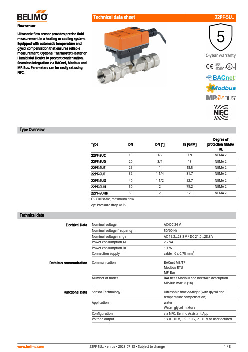
22PF-5U..Flow sensorUltrasonic flow sensor provides precise fluid measurement in a heating or cooling system. Equipped with automatic temperature and glycol compensation that ensures reliable measurement. Optional Thermostat Heater or Humidistat Heater to prevent condensation. Seamless integration via BACnet, Modbus andMP-Bus. Parameters can be easily set using NFC.Type OverviewType DN DN ["]FS [GPM]Degree of protection NEMA/UL22PF-5UC 151/27.9NEMA 222PF-5UD 203/413NEMA 222PF-5UE 25118.5NEMA 222PF-5UF 321 1/431.7NEMA 222PF-5UG 401 1/252.7NEMA 222PF-5UH 50279.2NEMA 222PF-5UHH502120NEMA 2FS: Full scale, maximum flow∆p: Pressure drop at FSTechnical dataElectrical DataNominal voltageAC/DC 24 V Nominal voltage frequency 50/60 HzNominal voltage range AC 19.2...28.8 V / DC 21.6...28.8 V Power consumption AC 2.2 VA Power consumption DC 1.1 WConnection supplycable , 6 x 0.75 mm²Data bus communicationCommunicationBACnet MS/TP Modbus RTU MP-BusNumber of nodesBACnet / Modbus see interface description MP-Bus max. 8 (16)Functional Data Sensor Technology Ultrasonic time-of-flight (with glycol and temperature compensation)Application waterWater-glycol mixture Configuration via NFC, Belimo Assistant AppVoltage output1 x 0...10 V, 0.5...10 V, 2...10 V or user defined22PF-5U..Functional Data Output signal active note DC 0...10 V (factory setting), selectable via NFCmax. load 1 mAUser defined:- Lower limit: 0...8 V- Upper limit: 2...10 VInstallation position upright to horizontalServicing maintenance-freeVelocity range0.08-7.73 FPSMeasuring Data Measured values FlowTemperatureMeasuring fluid chilled or hot water, up to 60% glycol max(open loop/steam not allowed)Measuring principle Ultrasonic volumetric flow measurementMeasuring accuracy flow±2% of the measured value (20...100% FS) @20°C / glycol 0% vol.±0.4% of FS (0...20% FS) @ 20°C / glycol 0% vol.Measuring accuracy flow note Additional information on measuring accuracy(with diagram) can be found in the section"Measuring accuracy".Measurement Repeatability±0.5% (Flow)Min. flow measurement0.2% of FSMaterials Fluid wetted parts Brass nickel-plated, Brass, Stainless steel, PEEK,EPDMFlow measuring pipe brass body nickel-platedSafety Data Protection class IEC/EN III, Protective Extra-Low Voltage (PELV)Power source UL Class 2 SupplyDegree of protection IEC/EN IP54Degree of protection NEMA/UL NEMA 2Enclosure UL Enclosure Type 2Certification IEC/EN IEC/EN 60730-1:11 and IEC/EN 60730-2-15:10Quality Standard ISO 9001UL Approval cULus acc. to UL94Type of action Type 1Rated impulse voltage supply0.8 kVPollution degree3Ambient humidity Max. 95% RH, non-condensingAmbient temperature-22...130°F [-30...55°C]-22...122°F [-30...50°C] (UL)Fluid temperature-5...250°F [-20...120°C]At a fluid temperature of < 2°C [< 36°F], frostprotection must be guaranteedStorage temperature-40...176°F [-40...80°C]Safety NotesThis device has been designed for use in stationary heating, ventilation and air-conditioningsystems and must not be used outside the specified field of application, especially in aircraft orin any other airborne means of transport.Outdoor applications: Only possible where (sea) water, snow, ice, sunlight or aggressive gasescannot interfere directly with the device and it can be guaranteed that the ambient conditionsremain at all times within the thresholds according to the data sheet.Only authorized specialists may carry out installation. All applicable legal or institutionalinstallation regulations must be complied during installation.The device contains electrical and electronic components and must not be disposed of ashousehold refuse. All locally valid regulations and requirements must be observed.22PF-5U..Mode of operationFunctionsPatented glycol compensationProduct FeaturesThe ultrasonic flow sensor is equipped with a flow pipe, two flow transmitters and an electronic circuit. A temperature sensor is mounted in the flow pipe to compensate the temperature effects.A sensor error occurs when the ultrasonic path is interrupted (air bubbles in the system, connection to ultrasonic transducers interrupted).Detailed error reports are available via Belimo Assistant App or BACnet, Modbus and MP-Bus.Collective error report displayIf the output signal is set to 0.5...10 V or 2...10 V and also to flow, a collective error report isdisplayed with a voltage of 0.3 V. This indicates a measurement error of the temperature sensor or flow sensor.Wires 6 and 7 are for the Modbus or BACnet communication. The physical bus address can be defined via the app.Wire 5 can be parametrized with the app as an output signal 0...10 V (factory setting), 0.5...10 V, 2...10 V, user defined or as an MP-Bus communication. For the output signal, the flow or the fluid temperature can be selected.The output signal can be scaled to achieve a better resolution. Factory setting is 10 V = FS (see diagram, example of output voltage characteristic curve 22PF-5UC).Example output voltage characteristic 22PF-5UCU = Output voltage q = Measured flow ∆ = Alternative settings□ = Factory settingGlycol changes the viscosity of the heat transfer fluid and as a result affects the measuredvolumetric flow. Without glycol compensation, volumetric flow measurements can show errors of as much as 30 percent. The patented automatic glycol compensation significantly reduces the degree of measurement error.Selection of the fluid used:– Water– Propylene glycol – Ethylene glycol – Antifrogen L – Antifrogen N – DowCal 200– DowCal 10022PF-5U..Measuring accuracyPressure dropMeasuring accuracy for water (glycol 0% vol.):±2% (@ 20…100% FS)At a temperature range of 15…120 °C.Measuring accuracy for water + glycol (glycol 0...60% vol.)±5% (@ 20…100% FS)±0.01 FS, but not more than 30% of q (@ 0.8…20% FS)At a temperature range of -20...120°C.— Water---- Water + glycol (≤60% glycol)y = Measuring accuracyq = Measured flowFS = Full scale, maximum flow22PF-5U..Recommended installation positionsInstallation in returnInlet sectionWater quality requirementsServicingFlow direction Avoiding cavitationCleaning of pipes Prevention of stressesInstallation notesThe sensor can be installed upright to horizontal. The sensor may not be installed in a hangingposition.Installation in the return is recommended.In order to achieve the specified measuring accuracy, a flow-calming section or inflow section in the direction of the flow is to be provided upstream from the flow sensor. Its dimensions shouldbe at least 5x DN.The water quality requirements specified in VDI 2035 must be adhered to.Sensors are maintenance-free.Before any service work on the sensor is carried out, it is essential to isolate the sensor from the power supply (by unplugging the electrical cables if necessary). Any pumps in the part of the piping system concerned must also be switched off and the appropriate slide valves closed (allow all components to cool down first if necessary and always reduce the system pressure to ambient pressure level).The system must not be returned to service until the sensor has been correctly reassembled in accordance with the instructions and the pipeline has been refilled by professionally trained personnel.The direction of flow, specified by an arrow on the housing, is to be complied with, since otherwise the flow rate will be measured incorrectly.To avoid cavitation, the system pressure at the outlet of the flow sensor must be a minimum of 1.0 bar at FS (maximum measurable flow) and temperatures up to 90°C.At a temperature of 120°C the system pressure at the outlet of the flow sensor must be at least 2.5 bar.Before installing the flow sensor, the loop must be thoroughly rinsed to remove impurities.The flow sensor must not be subjected to excessive stress caused by pipes or fittings.AccessoriesToolsDescriptionTypeBelimo Assistant App, Smartphone app for easy commissioning, parametrising and maintenance Belimo Assistant AppConverter Bluetooth / NFCZIP-BT-NFC22PF-5U..NFC connectionNotesServiceBelimo equipment marked with the NFC logo can be operated and configured using the Belimo Assistant App.Requirements:- Smartphone with NFC or Bluetooth- Belimo Assistant App (Available on Google Play & Apple AppStore)Smartphone with NFC:Place NFC-capable smartphone flat on the room sensor so that both NFC antennas are superposed.Smartphone with Bluetooth without NFC:Connect Bluetooth enabled smartphone via ZIP-BT-NFC (Bluetooth to NFC Converter) to the sensor. Technical data and operation instructions are shown on the ZIP-BT-NFC technical data sheet.Readable values: volumetric flow, accumulated flow, fluid temperature, glycol content in %,alarm/error messagesWiring DiagramSupply from isolating transformer.The wiring of the line for BACnet MS/TP / Modbus RTU is to be carried out in accordance with applicable RS485 regulations.Modbus / BACnet: Supply and communication are not galvanically isolated. Connect earth signal of the devices with one another.Sensor connection: An additional sensor can optionally be connected to the flow sensor. This can be an active sensor with output DC 0...10 V (max. DC 0...32 V with resolution 30 mV) or a switching contact (switching current min. 16 mA @ 24 V). Thus the analogue signal of the sensor can be easily digitized with the flow sensor and transferred to the corresponding bus system.Analogue output: An analogue output (wire 5) is available on the flow sensor. It can be selected as 0...10 V, 0.5...10 V, 2...10 V or user defined. For example, the flow rate or the temperature of the temperature sensor (Pt1000 - EN 60751, 2-wire technology) can be output as an analogue value.22PF-5U..AC/DC 24 V, output signalCable colours:1 = black, GND 2 = red, AC/DC 24 V3 = white, Sensor optional5 = orange, DC 0...10 V, MP-Bus6 = pink, C1 = D- = A7 = grey, C2 = D+ = BBACnet MS/TP / Modbus RTUMP-Bus, supply via 3-wire connection MP-Bus via 2-wire connection, local power supplyA) additional MP-Bus nodes (max. 8)A) additional MP-Bus nodes (max. 8)Connection with active sensorConnection with switching contactDimensions22PF-5U..Type DN DN ["]A_1B_1C_1D_1E_1F_1Weight22PF-5UC151/28.0" [203]4.7" [119]6.1" [154]5.5" [140]1.8" [46]1.8" [46] 1.7 lb[0.750 kg]22PF-5UD203/47.8" [198]5.9" [150]6.3" [159]5.5" [140]1.8" [46]1.8" [46] 1.7 lb[0.750 kg]22PF-5UE2518.4" [213]6.2” [157]6.4" [163]5.5" [140]1.8" [46]1.8" [46] 1.7 lb[0.750 kg]22PF-5UF321 1/48.6" [218]6.5" [165]6.7" [169]5.6" [142]1.8" [46]1.8" [46] 1.7 lb[0.750 kg]22PF-5UG401 1/28.8" [224]6.8" [173]7.0" [178]5.8" [148]1.8" [46]1.8" [46] 1.7 lb[0.750 kg]22PF-5UH5029.0" [229]7.1" [180]7.4" [187]6.0" [152]1.8" [46]1.8" [46] 1.7 lb[0.750 kg]22PF-5UHH5029.0" [229]7.1" [180]7.4" [187]6.0" [152]1.8" [46]1.8" [46] 1.7 lb[0.750 kg] Further documentation• Overview MP Cooperation Partners• Description Data-Pool Values• BACnet Interface description• Modbus Interface description• Installation instructions。
OMRON MEMS流量传感器D6F-V03A1说明书

The unique dust separating structure, developed by OMRON is a compact and highly efficient FLOW-SENSOR.•A dust-resistant design has been taken into consideration, by the original dust segregation structure, of OMRON.•+/-10% Full-Scale repeatable accuracy achieves consistent air velocity measurement.•Applications include clogged-filter detection and air velocity.Sensor specificationAbsolute maximum ratingOutput characteristicMeasurement condition: Power-supply voltage 3.3VDC, ambient temperature 25°C and dry air.Note:1.Air velocity is the value converted from the mass-flow in OMRON regulation wind tunnel phi48mm.2.The air velocity, set to the Measurement Law, is not shown. Please confirm in a real use environment in use.3.T emperature characteristics:Over ambient temperature range -10 to +60°C: within ±20% F .S. of detected characteristics Of at +25°C.Type D6F-V03A1Flow Range 0 – 3 m/s @ 25°C, 1 atmosphere Case Material Thermoplastic resin GasAirAmbient Temperature -10 to +60°C (with no condensation)Using Humidity Max. 85% RH (with no condensation)Storage Temperature -40 to +80°C (with no condensation)Preservation Humidity Max. 85% RH (with no condensation)Power Supply Voltage 3.15 to 3.45 VDCOutput Signal Analog output 0.5 to 2 VDC (non-linear output)Load resistance min. 10k ΩCurrent Consumption Max. 15mA (No-load, V CC = 3.3 VDC, 25°C)Insulation Resistance20Mohm min. (500VDC, between lead terminal and the case)Dielectric Withstanding Voltage Leakage current is 1mA max. (at 500 VAC, 50/60Hz for one minute).500VAC, 50/60Hz judged at 1mA max. (between the lead terminals and the case)ItemSymbol Rating Unit Power supply voltage V CC 12.0VDC Output voltageV OUT3.0VDCFlow Velocity (m/sec)00.75 1.50 2.25 3.00Output Voltage (VDC)0.50±0.150.70±0.151.11±0.151.58±0.152.00±0.15DimensionsOmron Electronic Components, LLCTerms and Conditions of Sales1.Definitions: The words used herein are defined as follows.(a) Terms:These terms and conditions(b) Seller:Omron Electronic Components LLC and its subsidiaries(c) Buyer:The buyer of Products, including any end user in section III through VI(d) Products:Products and/or services of Seller(e) Including:Including without limitation2.Offer; Acceptance: These Terms are deemed part of all quotations, acknowledgments,invoices, purchase orders and other documents, whether electronic or in writing, relating to the sale of Products by Seller. Seller hereby objects to any Terms proposed in Buyer's purchase order or other documents which are inconsistent with, or in addition to, these Terms.3.Distributor: Any distributor shall inform its customer of the contents after and includingsection III of these Terms.1.Prices; Payment: All prices stated are current, subject to change without notice by Seller.Buyer agrees to pay the price in effect at time of shipment. Payments for Products received are due net 30 days unless otherwise stated in the invoice. Buyer shall have no right to set off any amounts against the amount owing in respect of this invoice.2.Discounts: Cash discounts, if any, will apply only on the net amount of invoices sent toBuyer after deducting transportation charges, taxes and duties, and will be allowed only if (a) the invoice is paid according to Seller's payment terms and (b) Buyer has no past due amounts owing to Seller.3.Interest: Seller, at its option, may charge Buyer 1.5% interest per month or the maximumlegal rate, whichever is less, on any balance not paid within the stated terms.4.Orders: Seller will accept no order less than 200 U.S. dollars net billing.5.Currencies: If the prices quoted herein are in a currency other than U.S. dollars, Buyershall make remittance to Seller at the then current exchange rate most favorable to Seller; provided that if remittance is not made when due, Buyer will convert the amount to U.S. dollars at the then current exchange rate most favorable to Seller availableduring the period between the due date and the date remittance is actually made.ernmental Approvals: Buyer shall be responsible for all costs involved in obtainingany government approvals regarding the importation or sale of the Products.7.Taxes: All taxes, duties and other governmental charges (other than general real propertyand income taxes), including any interest or penalties thereon, imposed directly orindirectly on Seller or required to be collected directly or indirectly by Seller for themanufacture, production, sale, delivery, importation, consumption or use of the Products sold hereunder (including customs duties and sales, excise, use, turnover and license taxes) shall be charged to and remitted by Buyer to Seller.8.Financial: If the financial position of Buyer at any time becomes unsatisfactory to Seller,Seller reserves the right to stop shipments or require satisfactory security or payment in advance. If Buyer fails to make payment or otherwise comply with these Terms or any related agreement, Seller may (without liability and in addition to other remedies) cancel any unshipped portion of Products sold hereunder and stop any Products in transit until Buyer pays all amounts, including amounts payable hereunder, whether or not then due, which are owing to it by Buyer. Buyer shall in any event remain liable for all unpaid accounts.9.Cancellation; Etc: Orders are not subject to rescheduling or cancellation unless Buyerindemnifies Seller fully against all costs or expenses arising in connection therewith. 10.Force Majeure: Seller shall not be liable for any delay or failure in delivery resulting fromcauses beyond its control, including earthquakes, fires, floods, strikes or other labor disputes, shortage of labor or materials, accidents to machinery, acts of sabotage, riots, delay in or lack of transportation or the requirements of any government authority.11.Shipping; Delivery: Unless otherwise expressly agreed in writing by Seller:(a) All sales and shipments of Products shall be FOB shipping point (unless otherwisestated in writing by Seller), at which point title to and all risk of loss of the Products shall pass from Seller to Buyer, provided that Seller shall retain a security interest in theProducts until the full purchase price is paid by Buyer;(b) Delivery and shipping dates are estimates only; and(c) Seller will package Products as it deems proper for protection against normalhandling and extra charges apply to special conditions.12.Claims: Any claim by Buyer against Seller for shortage or damage to the Productsoccurring before delivery to the carrier must be presented in detail in writing to Seller within 30 days of receipt of shipment.1.Suitability: IT IS THE BUYER’S SOLE RESPOINSIBILITY TO ENSURE THAT ANYOMRON PRODUCT IS FIT AND SUFFICIENT FOR USE IN A MOTORIZED VEHICLE APPLICATION. BUYER SHALL BE SOLELY RESPONSIBLE FOR DETERMINING APPROPRIATENESS OF THE PARTICULAR PRODUCT WITH RESPECT TO THE BUYER’S APPLICATION INCLUDING (A) ELECTRICAL OR ELECTRONICCOMPONENTS, (B) CIRCUITS, (C) SYSTEM ASSEMBLIES, (D) END PRODUCT, (E) SYSTEM, (F) MATERIALS OR SUBSTANCES OR (G) OPERATING ENVIRONMENT.Buyer acknowledges that it alone has determined that the Products will meet theirrequirements of the intended use in all cases. Buyer must know and observe allprohibitions of use applicable to the Product/s.e with Attention: The followings are some examples of applications for whichparticular attention must be given. This is not intended to be an exhaustive list of all possible use of any Product, nor to imply that any use listed may be suitable for any Product:(a) Outdoor use, use involving potential chemical contamination or electricalinterference.(b) Use in consumer Products or any use in significant quantities.(c) Energy control systems, combustion systems, railroad systems, aviation systems,medical equipment, amusement machines, vehicles, safety equipment, andinstallations subject to separate industry or government regulations.(d) Systems, machines, and equipment that could present a risk to life or property.3.Prohibited Use: NEVER USE THE PRODUCT FOR AN APPLICATION INVOLVINGSERIOUS RISK TO LIFE OR PROPERTY WITHOUT ENSURING THAT THE SYSTEM AS A WHOLE HAS BEEN DESIGNED TO ADDRESS THE RISKS, AND THAT THE PRODUCT IS PROPERLY RATED AND INSTALLED FOR THE INTENDED USEWITHIN THE OVERALL EQUIPMENT OR SYSTEM.4.Motorized Vehicle Application: USE OF ANY PRODUCT/S FOR A MOTORIZEDVEHICLE APPLICATION MUST BE EXPRESSLY STATED IN THE SPECIFICATION BY SELLER.5.Programmable Products: Seller shall not be responsible for the Buyer's programming ofa programmable Product.1.Warranty: Seller's exclusive warranty is that the Products will be free from defects inmaterials and workmanship for a period of twelve months from the date of sale by Seller (or such other period expressed in writing by Seller). SELLER MAKES NO WARRANTY OR REPRESENTATION, EXPRESS OR IMPLIED, ABOUT ALL OTHER WARRANTIES, NON-INFRINGEMENT, MERCHANTABILITY OR FITNESS FOR A PARTICULARPURPOSE OF THE PRODUCTS.2.Buyer Remedy: Seller's sole obligation hereunder shall be to replace (in the formoriginally shipped with Buyer responsible for labor charges for removal or replacement thereof) the non-complying Product or, at Seller's election, to repay or credit Buyer an amount equal to the purchase price of the Product; provided that there shall be noliability for Seller or its affiliates unless Seller's analysis confirms that the Products were handled, stored, installed and maintained and not subject to contamination, abuse,misuse or inappropriate modification. Return of any Products by Buyer must beapproved in writing by Seller before shipment.3.Limitation on Liability: SELLER AND ITS AFFILIATES SHALL NOT BE LIABLE FORSPECIAL, INDIRECT, INCIDENTAL OR CONSEQUENTIAL DAMAGES, LOSS OF PROFITS OR PRODUCTION OR COMMERCIAL LOSS IN ANY WAY CONNECTED WITH THE PRODUCTS, WHETHER SUCH CLAIM IS BASED IN CONTRACT,WARRANTY, NEGLIGENCE OR STRICT LIABILITY. FURTHER, IN NO EVENT SHALL LIABILITY OF SELLER OR ITS AFFILITATES EXCEED THE INDIVIDUAL PRICE OF THE PRODUCT ON WHICH LIABILITY IS ASSERTED.4.Indemnities: Buyer shall indemnify and hold harmless Seller, its affiliates and itsemployees from and against all liabilities, losses, claims, costs and expenses (including attorney's fees and expenses) related to any claim, investigation, litigation or proceeding (whether or not Seller is a party) which arises or is alleged to arise from Buyer's acts or omissions under these Terms or in any way with respect to the Products.1.Intellectual Property: The intellectual property embodied in the Products is the exclusiveproperty of Seller and its affiliates and Buyer shall not attempt to duplicate it in any way without the written permission of Seller. Buyer (at its own expense) shall indemnify and hold harmless Seller and defend or settle any action brought against Seller to the extent that it is based on a claim that any Product made to Buyer specifications infringedintellectual property rights of another party.2.Property; Confidentiality: Notwithstanding any charges to Buyer for engineering ortooling, all engineering and tooling shall remain the exclusive property of Seller. All information and materials supplied by Seller to Buyer relating to the Products areconfidential and proprietary, and Buyer shall limit distribution thereof to its trustedemployees and strictly prevent disclosure to any third party.3.Performance Data: Performance data is provided as a guide in determining suitabilityand does not constitute a warranty. It may represent the result of Seller's test conditions, and the users must correlate it to actual application requirements.4.Change In Specifications: Product specifications and description may be changed at anytime based on improvements or other reasons. It is Seller’s practice to change part numbers when published ratings or features are changed, or when significantengineering changes are made. However, some specifications of the Product may be changed without any notice.5.Errors And Omissions: The information on Seller’s website or in other documentationhas been carefully checked and is believed to be accurate; however, no responsibility is assumed for clerical, typographical or proofreading errors or omissions.6.Export Controls: Buyer shall comply with all applicable laws, regulations and licensesregarding (a) export of the Products or information provided by Seller; (b) sale ofProducts to forbidden or other proscribed persons or organizations; (c)disclosure to non-citizens of regulated technology or information.1.Waiver: No failure or delay by Seller in exercising any right and no course of dealingbetween Buyer and Seller shall operate as a waiver of rights by Seller.2.Assignment: Buyer may not assign its rights hereunder without Seller's written consent.w: These Terms are governed by Illinois law (without regard to conflict of laws). Federaland state courts in Illinois have exclusive jurisdiction for any dispute hereunder.4.Amendment: These Terms constitute the entire agreement between Buyer and Sellerrelating to the Products, and no provision may be changed or waived unless in writing signed by the parties.5.Severability: If any provision hereof is rendered ineffective or invalid, such provision shallnot invalidate any other provision.Certain Precautions on Specifications and UseOMRON ON-LINEGlobal - USA - Cat. No. J01C-E-01Printed in USAOMRON ELECTRONIC COMPONENTS LLC55 E. Commerce Drive, Suite B Schaumburg, IL 60173847-882-228801/07 Specifications subject to change without noticeComplete “Terms and Conditions of Sale” for product purchase and use are on Omron’s website at – under the “About Us” tab, in the Legal Matters section.ALL DIMENSIONS SHOWN ARE IN MILLIMETERS.T o convert millimeters into inches, multiply by 0.03937. To convert grams into ounces, multiply by 0.03527.。
KROHNE FMG7 0B Series 磁导化流量传感器操作手册说明书

FMG70B SeriesMagnetic Inductive Flow Sensor- 2 -M-5575/0416Table of contents page 0About this operating manual (4)1Device description (5)1.1Delivery, unpacking and accessories (5)1.2Intended use (6)1.3Exclusion of liability (6)2Safety instructions (7)3Construction and function (8)4Installation of FMG70B (9)4.1Installation instructions (9)4.2Mounting (10)5Electrical connection (11)5.1Wirings (12)6Commissioning and measuring mode (13)6.1Commissioning (13)6.2Switching on and off (13)6.3Measuring mode (13)7Maintenance and cleaning (15)7.1Return shipment to the manufacturer (15)8Disassembly and disposal (16)9Technical data (17)9.1Characteristics FMG70B (17)9.2Materials table (18)9.3Pressure drop (18)9.4Temperature limits (19)9.5Dimensions (20)Copyright notice:The reproduction, distribution and utilization of this operating manual as well as the communication of its contents to others without express authorization is prohibited. Offenders will be held liable for the payment of damages. All rights reserved in the event of the grant of a patent, utility model or design.Technical changes reserved - 3 -About this operating manual- 4 - M-5575/04160 About this operating manual• The operating manual is aimed at specialists and semi-skilled personnel.• Before each step, read through the relevant advice carefully and keep to the specified order.•Thoroughly read and understand the information in the section "Safety instructions".If you have any problems or questions, please contact your supplier or contact us directly at:One Omega Drive, P.O. Box 4047Stamford, CT 06907-0047 Tel: (203) 359-1660 e-mail:**************Hazard signs and other symbols used:WARNING! / CAUTION! Risk of injury!This sign indicates dangers that cause personal injuries that can lead to health defects or cause considerable damage to property.CAUTION! Electric current!This sign indicates dangers which could arise from handling of electric current.CAUTION! Material damage!This sign indicates actions which could lead to possible damage to material or environmental damage.ADHERE TO OPERATING MANUAL! NOTICE!This symbol indicates important notices, tips or information. NO DOMESTIC WASTE!The device must not be disposed of together with domestic waste.Pay attention to and comply withinformation that is marked with this symbol.Follow the specified instructions and steps.Adhere to the given order.❑Check the specified points or notices.Reference to another section, document orsource. • Item.Device descriptionTechnical changes reserved - 5 -1 Device descriptionThe FMG70B series from Omega, is a non-contact flow sensor. The measurement is performed using magnetic induction and works without any moving parts.The FMG70B is used for measuring or metering water and aqueous solutions. The compact design and independence from the intake and discharge sections allows the FMG70B to be used under a variety of conditions.Versions ∗:The FMG70B is available with inner diameters 0.39 in narrows to 0.16 in, 0.39 in and 0.79 in.The versions can be configured differently (♑ FMG70B data sheet).Type plate:The type plate sticker is located at the bottom side of the FMG70B.It contains the most important data, the connection diagram and the arrow for the flow direction (Example ♑ Fig.).1.1 Delivery, unpacking and accessoriesAll units have been carefully checked for their operational reliability before shipment.❒ Immediately after receipt, please check the outer packaging for damages or any signs ofimproper handling.❒ Report any possible damages to the forwarder and your responsible salesrepresentative. In such a case, state a description of the defect, the type and the serial number of the device.Report any in-transit damage immediately. Damage reported at a later date shall not be recognized. Unpacking:Carefully unpack the unit to prevent any damage.Check the completeness of the delivery based on the delivery note. Scope of delivery:❒ 1x FMG70B as ordered.❒1x Operating manual. ❒ 1x Packing.∗Customised versions available on request.Device description- 6 - M-5575/0416IMPORTANT!Use the type plate to check if the delivered unit corresponds to your order.In particular, for devices with electrical components, check to see if the correct power supply voltage is specified.Accessories:❒ Connection cable with moulded M12x1 couplingsocket.❒ M12x1 coupling socket as component.1.2 Intended useThe magnetic inductive flow sensor FMG70B must only be used for measuring and metering liquids with a minimum conductivity of 50 μS/cm.WARNING! No safety component!The magnetic inductive flow sensor of the series FMG70B is not safety components in accordance with Directive 2006-42-EC (Machine Directive). Never use the FMG70B as a safety component.The operational safety of the device supplied is only guaranteed by intended use. The specified limits (♑ § 9 "Technical data") may under no circumstances be exceeded.Before installing the device, check that the wetted materials of the device are compatible with the media being used (♑ § 9.2 "Materials table").Measuring tube empty (or partially filled). / Conductivity too low.The green LED may blink irregularly if the measuring tube of the FMG70B is empty or partially filled or if the conductivity of the fluid being used is too low. Random impulses will be present at the output, but they do not represent an actual flow.Ensure that the measuring tube of the FMG70B is always completely filled (♑ § 4.1 "Installation instructions").Ensure that the conductivity of the fluid is at least 50 μS/cm.1.3Exclusion of liabilityWe accept no liability for any damage or malfunctions resulting from incorrect installation, in-appropriate use of the device or failure to follow the instructions in this operating manual.Safety instructionsTechnical changes reserved - 7 -2Safety instructionsBefore you install the FMG70B, read through this operating manual carefully. If the instructions contained within it are not followed, in particular the safety guidelines, this could result in danger for people, the environment, and the device and the system it isconnected to.The FMG70B correspond to the state-of-the-art technology. This concerns the accuracy, the operating mode and the safe operation of the device.In order to guarantee that the device operates safely, the operator must act competently andbe conscious of safety issues.Omega provides support for the use of its products either personally or via relevant literature. The customer verifies that our product is fit for purpose based on our technical information. The customer performs customer- and application-specific tests to ensure that the product issuitable for the intended use. With this verification all hazards and risks are transferred to our customers; our warranty is not valid.Qualified personnel:The personnel who are charged for the installation, operation and maintenance of the FMG70B must hold a relevant qualification. This can be based on training or relevanttuition.The personnel must be aware of this operating manual and have access to it at all times.The electrical connection should only be carried out by a fully qualified electrician. General safety instructions:In all work, the existing national regulations for accident prevention and safety in the workplace must be complied with. Any internal regulations of the operator must also becomplied with, even if these are not mentioned in this manual. Degree of protection according to EN 60529:Please ensure that the ambient conditions at the site of use does not exceed the requirements for the stated protection rating ( § 9 "Technical data").Prevent freezing of the medium in the device with appropriate measures.Only use the FMG70B if it is in perfect condition. Damaged or faulty devices must be checked without delay and, if necessary, replaced.When fitting, connecting and removing the FMG70B use only suitable appropriate tools. Do not remove or obliterate type plates or other markings on the device, as otherwise the warranty is rendered null and void. Special safety instructions:Warnings that are specifically relevant to individual operating procedures or activities can be found at the beginning of the relevant sections of this operating manual.Construction and function- 8 - M-5575/04163 Construction and functionComponents:① Housing:The housing consists of aluminum die casting and has the IP65 degree of protection.② Electrical connection:The electrical connection is made via 5-pin plug M12x1.③ Operation / flow indicator LED.④ Process connection:The process connections are available in different sizes.⑤ Type plate (sticker).Construction:The measuring tube with its earthing sleeves and electrodes passes through the housing and forms the external process connection of the FMG70B.A magnetic field for the measurement process is generated inside the sensor housing, which also contains the sensor and signal conditioning circuitry.The two stainless steel electrodes are located in the middle of the measuring tube between the earthing sleeves. The FMG70B does not need any moving parts to make measurements. The inside of the measuring tube is completely open, allowing the fluid to flow unhindered through the measuring tube.Function:The magnetic inductive flow sensor operates in accordance with the principle of induction, i.e. a DC voltage is generated by the movement of a conductor in a magnetic field:The measuring tube of the FMG70B is located in a magnetic field (B).An electrically conductive liquid (Q) flows through the measuring tube. The positive and negative charge carriers are deflected in opposite directions. A voltage perpendicular to the magnet field is generated and picked up by the two electrodes. The resulting induced voltage is proportional to the mean flow velocity of the liquid.The electronics of the FMG70B converts the induced voltage to a flow-proportional frequency signal.Installation of FMG70BTechnical changes reserved- 9 -4 Installation of FMG70BBefore installing, check that❒ the wetted materials of the device are suitable for the liquid being used ( § 9.2"Materials table").❒ the equipment is switched off and is in a safe and de-energized state. ❒ the equipment is depressurized and has cooled down.SUITABLE TOOLS:Use only suitable tools of the correct size.4.1 Installation instructionsCAUTION! Risk of malfunction due to external magnetic fields!Magnetic fields close to the device can cause malfunctions and should be avoided.Ensure that no external magnetic fields are present at theinstallation site of the FMG70B.•The FMG70B can always be installed anywhere along the pipeline. Straight sections of piping are preferable, however.Installation of FMG70B- 10 - M-5575/0416• Installation can occur in horizontal and vertical pipes. The flow sensor is only suitable for application in completely filled pipe systems.•As a matter of principle magnetic inductive flow sensors are widely independent from the flow profile. An inlet section is not absolutely necessary.To reach a most highly accuracy of the measurement, you should use straight inlet and outlet sections according to the inner diameter. The inlet section has to be at least10 x inner diameter; the outlet section 5 x inner diameter in order to achieve the specified accuracy.• The inlet and outlet sections and gaskets must have the same or a slightly larger inside diameter than the measuring tube in order to achieve the specified accuracy.4.2 MountingThe FMG70B is installed directly into the pipeline. The compact design and light weight of the unit make wall-mounting unnecessary.IMPORTANT NOTICES:• Observe the flow direction indicated on the FMG70B.• Observe the mounting dimensions (♑ § 9.5 "Dimensions").Select an appropriate location for installation (♑ § 4.1"Installation instructions").To ensure the best possible measuring accuracy, a vertical installation position with increasing flow is preferable (no collecting of dirt deposits).Wrap the FMG70B connections with 1 to 2 wraps of threadtape (e.g. Teflon ® tape).Wrap tape in a clockwise direction, viewed form the end, leaving the first two threads uncovered.Make sure the tape does not intrude into the flow path.Attach the FMG70B with arrow pointed in the direction of flow. The fittings should be screwed into FMG70B hand tight.CAUTION! Material damage!Do not use excessive force. The FMG70B can be damaged.While tightening, counter the union nut on the hexagon of the process connection!If you do not counter it, the FMG70B can be damaged!Use two wrenches to tighten the FMG70B an additional ¾ to 1 turn.When tightening, use a wrench (AF 1.063 or AF 1.338) to counter the process connection on the hexagon (flange) in place.Electrical connection5 Electrical connectionThe electrical connection of the FMG70B is via the 5-pin plug M12x1 at the top of the housing.The wiring of the FMG70B depends on the ordered version. A distinction is made between frequency and analog output, as well as basic and optional wiring.CAUTION! Electric current!The electrical connection should only be carried out by a fully qualified electrician. De-energize the electrical system before connecting the FMG70B.CAUTION! Material damage and fire hazard!Exceeding the specified limits will cause damage to the electronics. Without current limiting, there is a fire hazard due to overheating of the device. Connect the FMG70B only to a power source with limited power.Optional wirings:Depending on the version, an analog output can be optionally connected.Connecting cable:Suitable connection cables with molded coupling socket are available in various lengths included in the range of Omega accessories. The shielding is already connected with the knurled nut.IMPORTANT! Shielding required!Use only shielded connection cables.The shield of the connection cable should not be connected to earth.We recommend to ground the pipes directly before and behind the FMG70B (♑ Figure).IMPORTANT NOTICE:Pay attention to the temperature resistance of the connecting cable (♑ § 9 "Technicaldata") at high media temperatures.If the temperature resistance is smaller than the medium temperature, the cable may notbe directly laid on the pipe.Connection 5-pin plug M12x1:Screw the coupling socket of the connection cable to the plug of the FMG70B. Tighten the knurled nut of the coupling socket with a maximum torque of 1 Nm.Electrical connection5.1 WiringsPinout:The pinout differs according to the chosen configuration of the device.M12x1Possible pinout: Pin 1: +U BPin 2: n. c. (not connected) / Analog U/I Pin 3: GNDPin 4: FrequencyPin 5: n. c. (not connected) / d. n. c. (do not connect)Connect the connecting cable according to your version and the pinout on the type plate.Supply voltage:FMG70B with frequency output:Push-Pull *1:NPN Open Collector:PNP Open Collector:*1: Push-Pull switching outputs of several FMG70B may not be connected in parallel. *2: Recommendation Pull-Up / Pull-Down resistance R L ~5 k ΩUse of frequency and analog output:Recommendation for resistance R ~5 k ΩCommissioning and measuring mode6 Commissioning and measuring modeBefore switching on the FMG70B for the first time, please follow the instructions in the following section.6.1 CommissioningCheck that❒the FMG70B has been installed correctly and that all screw connections are sealed.❒the electrical wiring has been connected properly.❒the measuring system is vented by flushing.6.2 Switching on and offThe FMG70B has no switch and can therefore not be switched on and off independently. Switching on and off takes place via the connected supply voltage.Switch on the supply voltage.goes into measuring operation.6.3 Measuring modeIn measuring mode, the green LED flashes proportional to the measured flow.frequency of ~30 ... 40 Hz.In that case the green LED seems to be lit permanently.The following subsections only apply to devices which have the correspondent functionality.ing subsections only apply to devices which have the correspondent functionality.FMG70B with frequency output:The FMG70B provides according to the version a flowproportional NPN, PNP or Push-Pull square wavesignal.The frequency of the pulse output changes accordingto the flow ( Fig.).Commissioning and measuring mode FMG70B with analog output:According to the configuration of theFMG70B, the analog output provides a voltage or current signal.This signal is proportional to the measured flow.Maintenance and cleaning7 Maintenance and cleaningMaintenance:The FMG70B is maintenance-free and cannot be repaired by the user. In case of a defect, the device must be replaced or sent back the manufacturer for repair.CAUTION! Material damage!When opening the device, critical parts or components can be damage. Never open the device and perform any repair yourself.Cleaning:Clean the FMG70B with a dry or slightly damp lint-free cloth. Do not use sharp objects or aggressive agents for cleaning.7.1 Return shipment to the manufacturerDue to legal requirements placed on environmental protection and occupational safety and health and to maintain the health and safety of our employees, all units returned to Omega for repair must be free of toxins and hazardous substances. That also applies to cavities in the devices. If necessary, the customer must neutralize or purge the unit before return to Omega.Costs incurred due to inadequate cleaning of the device and possible costs for disposal and/or personal injuries will be billed to the operating company.WARNING! Risk of injury due to insufficient cleaning!The operating company is responsible for all damages and harm of any kind, in particular physical injuries (e.g. caustic burns or toxic contaminations), decontamination measures, disposal etc. that can be attributed to insufficient cleaning of the measuring instrument. Please follow the instructions for sending in returns shown on page 23 of this manual.The following measures must be taken before you send the unit to Omega for repair:Clean the device thoroughly. This is of extreme importance if the medium is hazardous tohealth, i.e. caustic, toxic, carcinogenic or radioactive etc.Remove all residues of the media and pay special attention to sealing grooves and slits. Attach a note describing the malfunction, state the application field and thechemical/physical properties of the media.Please specify a point of contact in case our service department has any questions.Disassembly and disposal8 Disassembly and disposalCAUTION! Risk of injury!Never remove the device from a plant in operation.Make sure that the plant is shut down professionally.Before disassembly:Prior to disassembly, ensure that❒ the equipment is switched off and is in a safe and de-energized state. ❒ the equipment is depressurized and has cooled down. Disassembly:Remove the electrical connectors.Remove the FMG70B using suitable tools.Disposal:NO HOUSEHOLD WASTE!The FMG70B consists of various different materials. He must not be disposed of with household waste.Take the FMG70B to your local recycling plantTechnical data9 Technical dataThe technical data of customized versions may differ from the data in these instructions. Please observe the information specified on the type plate.9.1 Characteristics FMG70B*2 factory setting.*3 other range on request.Technical datathe FMG70B.9.2 Materials table9.3 Pressure dropFMG71B and FMG72B: FMG73B:Technical data 9.4 Temperature limitsThe maximum ambient temperature depends on the medium temperature and the version of the FMG70B.Technical data9.5 DimensionsFMG71B and FMG72B:¾'' NPT only for FMG72B.The cross section of the FMG72B does not taper to 0.16 in.FMG73B:For your notes For your notesFor your notesFor your notesM-5575/0416。
OMRON F3S长距离检测型单光束安全传感器 说明书
长距离检测型单光束安全传感器F3SSᅝܼ Ӵᛳ఼相关信息 产品线...................................F-26 共通注意事项 ........................ 后-2 技术指南 ................................ 46560m的长距离检测。
最适合于流水线上整体的防护及大型设备的 多面侵入检测等人体检测用(4级)的对射型光电传感器■最多4套可防止相互间干扰 ■符合IEC标准,北美标准 (已取得IEC61496-1、 -2、 UL/CSA标准的认证) 可以作为北美劳动安全现场所必须的OSHA规范中规定的安全防护装置使用 ■不需要专用控制器。
只用传感器便可实现人体侵入检测功能 ■具有防止输出自动复位的 “启动/重启互锁功能” 。
F3SJ F3SN-A F3SN-B F3SH-A F3SL■投/受光透镜上安装加热器。
■即使在发生结露的环境下也可以安心使用 ■备有玻璃制和不锈钢制的反射镜作为可选件请参照294页 「请正确使用」 。
E3FS E3ZS F3SS种类主体检测方式 形状 外壳材质 连接方法 内部基板上的 端子台连接 检测距离 输出规格 组合型号(交货期请向经销商咨询)㑶ܝ对射型铝0.360mPNP输出F3SS-AT60P注. 投光器:F3SS-AT60P-L受光器:F3SS-AT60-D也可以单独订购。
附件(另售)种类 激光校准工具(光轴调整用) 玻璃反射镜 不锈钢反射镜 45度反射镜金属安装配件 墙壁用反射镜金属安装配件 φ42圆柱传感器金属安装配件注. 配线是内置端子台方式。
请另行准备配线用φ4~φ7电缆。
型号 F39-LLK F39-MSG F39-MSS F39-LM45 F39-LA F39-LSP290长距离检测型单光束安全传感器F3SS额定值/性能项目 检测方式 外壳材质 连接方法 电源电压 有效开口角 消耗电流 检测距离 标准检测物体 响应时间 控制输出 型号 F3SS-AT60P 对射型 铝(外壳、盖) 由内部基板上的端子台连接 DC24V±10% 波纹(p-p) ±2.5°(3m的情况下) 投光器:170mA以下 受光器:800mA以下 0.3~60m φ31mm以上的不透明体 35ms以下 PNP晶体管输出×2输出 负载电流:250mA输出残留电压1V以下(因导线延长的电压降除外) 入光时ON 自动启动模式 启动互锁模式 启动/重启互锁模式 用受光器内的切换开关可以选择任一模式 4s以内 工作时·保存时:各0~+55℃ (不结冰、不结露) 工作时·保存时:各35~95%RH (不结冰、不结露) 误操作·耐久:10~55Hz 双振幅0.77mmX、 Y、 Z各方向20次 误操作·耐久:100m/s2X、 Y、 Z各方向1000次 IEC标准IP65 红外发光二极管(880nm) 投光器:橙/表示电源、红/表示故障 受光器:橙/表示光量、红/表示遮光、绿/表示投光、黄/表示互锁 电源接反保护、负载短路保护 约2.5kg(1套) IEC(EN)61496-1 Type4 ESPE *1 IEC(prEN)61496-2 Type4 AOPD *2 使用说明书、金属安装配件一套、导管用盖ᅝܼ Ӵᛳ఼工作模式 电源接通后启动时间 环境温度 环境湿度 耐振动 耐冲击 保护结构 光源 表示 保护电路 重量(包装状态) 适用标准 附件F3SJ F3SN-A F3SN-B F3SH-A F3SLE3FS E3ZS F3SS*1. Electro-Sensitive Protective Equipment *2. Active Opto-electronic Protective Device连接将所有的电源切断之后,进行F3SS的配线。
FESTO SFAB流量传感器说明书
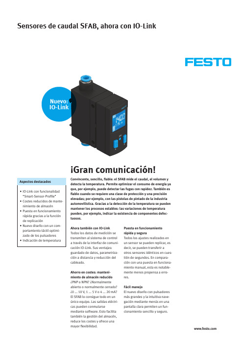
¡Gran comunicación!Ahora también con IO-LinkTodos los datos de medición setransmiten al sistema de controla través de la interfaz de comuni-cación IO-Link. Sus ventajas:guardado de datos, parametriza-ción a distancia y reducción delcableado.Ahorro en costes: manteni-miento de almacén reducido¿PNP o NPN? ¿Normalmenteabierto o normalmente cerrado?¿0 ... 10 V, 1 ... 5 V o 4 ... 20 mA?El SFAB lo consigue todo en unúnico equipo. Las salidas eléctri-cas pueden conmutarsemediante software. Esto facilitatambién la gestión del almacén,reduce los costes y ofrece unamayor flexibilidad.Puesta en funcionamientorápida y seguraTodos los ajustes realizados enun sensor se pueden replicar, esdecir, se pueden transferir aotros sensores idénticos en cues-tión de segundos. En compara-ción con una puesta en funciona-miento manual, esta es notable-mente menos propensa a erro-res.Fácil manejoEl nuevo diseño con pulsadoresmás grandes y la intuitiva nave-gación mediante menús en unapantalla clara permiten un fun-cionamiento sencillo y seguro.Convincente, sencillo, fiable: el SFAB mide el caudal, el volumen ydetecta la temperatura. Permite optimizar el consumo de energía yaque, por ejemplo, puede detectar las fugas con rapidez. También esfiable cuando se requiere una clase de protección y una precisiónelevadas; por ejemplo, con las pistolas de pintado de la industriaautomovilística. Gracias a la detección de la temperatura se puedenmantener los procesos estables: las variaciones de temperaturapueden, por ejemplo, indicar la existencia de componentes defec-tuosos.142555 e s 2022/04 – R e s e r v a d o e l d e r e c h o a m o d i fi c a c i o n e s y e r r o r e sSensor de caudal SFAB con IO-Link y numerosas funciones • Supervisión con función de programación mediante apren-dizaje Teach In o mediante introducción de valores • Salida de valores de caudal volumétrico y caudal másico en las habituales unidades de medida de caudal• Salida de conmutación con pulso de volumen ajustable • Puede cambiar entre 3 condi-ciones estándar• Código de seguridad libre-mente seleccionable y ajusta-ble (código de 4 dígitos)• Filtro de paso bajo ajustable para el alisado de la señal de caudal• Escala de la salida analógica en el rango de medición nece-sario en la aplicación• Compensación de offset opcio-nal• Memoria de valores mín./máx.Pantalla orientable para una lectura óptimaDentro del rango de consignaFuera del rango de consignaEspecificaciones técnicas Rango de medición del caudal [l/min]0,1 ... 100,5 (50)2 (200)6 (600)10 (1000)Sentido de flujo UnidireccionalMagnitud medidaCaudal másico, caudal volumétrico, temperatura Presión de funcionamiento [MPa]0 ... 0,1Rango de temperaturas [°C]0 … +50Grado de protección IP65Salidas eléctricas Salida 1: PNP/NPN/IO-LinkSalida 2: PNP/NPN/0 … 10 V/1 … 5 V/4 … 20 mA Conexiones neumáticas QS6, QS8, QS10, QS12, QS1/4, QS5/16, QS3/8Conexión eléctrica M12, 4 contactosTipos de fijación Fijación mediante carril DIN, montaje mural con taladro pasante/montaje con placas PantallaOrientable¡Señales claras!El cambio de color azul/rojo de toda la pantalla de dos líneas, visible desde la distancia, muestra de inme-diato si todo está correcto o si no se ha alcanzado el rango de consigna. El rango de consigna del valor de medición se visualiza intuitiva y fácilmente. La pantalla orientable permite una fácil lectura en cualquier posición.。
欧姆龙传感器

更换故障传感器
维修电路故障
• 选择相同类型、性能的传感器
• 检查电路元件、接线是否正常
• 更换传感器并重新调试
• 维修或更换故障元件、接线
06
欧姆龙传感器的发展趋势与市场前景
欧姆龙传感器的技术发展趋势
提高传感器的精度与稳定性
• 采用新型传感技术、材料
• 优化生产工艺、质量控制体系
扩展传感器的应用领域
长期稳定的供货能力
大规模的生产能力
完善的供应链管理
• 高效的生产线、先进的设备
• 稳定的原材料供应
• 保证产品的高产量、高质量
• 及时的物流配送
04
欧姆龙传感器的选型与安装
欧姆龙传感器的选型原则
根据应用场景选择传感器类型
• 温度、湿度、压力、振动、接近、光传感器
考虑传感器的性能参数
• 分辨率、精度、量程、供电、输出
DOCS SMART CREATE
欧姆龙传感器:原理、应用与优势
CREATE TOGETHER
DOCS
01
欧姆龙传感器产品概述
欧姆龙传感器种类及特点
欧姆龙传感器种类繁多
高精度与高稳定性
广泛的兼容性
• 温度传感器
• 采用先进的传感技术
• 适用于各种环境条件
• 湿度传感器
• 严格的质量控制体系
• 与各类设备兼容
• 压力传感器
• 长期稳定的性能表现
• 满足不同行业需求
• 振动传感器
• 接近传感器
• 光传感器
欧姆龙传感器工作原理
传感器工作原理概述
• 将物理量转换为电信号
• 通过电子电路进行处理
• 输出标准信号或数字信号