[方案][存储]XX大学CISCO MDS9124和BRACODE 3850级联实施方案
cisco3550暗码康复进程
cisco3550暗码康复进程cisco3550暗码康复进程一、将一台终端或装有超级终端软件的PC接到沟通机的console口上。
终端参数设置如下:速率:9600bps检较位:无数据位:8接连位:1流控:无二、拨掉电源三、按住前面板的mode键不放,插上电源,等3-5秒后松开mode键。
你会看到如下提示:Thesystemhasbeeninterruptedpriortoinitializingtheflashfilesystem.Thefollowingcommandswillinitializetheflashfilesystem,andfinishload ingtheoperatingsystemsoftware:flash_initload_helperboot四、输入flash_init五、输入load_helper六、输入dirflash:留神,不要少了flash后边的冒号,屏幕呈现如下提示。
Directoryofflash:2-rwx843947Mar01199300:02:18C2900XL-c3h2s-mz-12.1-WC5.bin 4drwx3776Mar01199301:23:24html66-rwx130Jan01197000:01:19env_vars68-rwx1296Mar01199306:55:51config.text1728000bytestotal(456704bytesfree)七、输入renameflash:config.textflash:config.old八、输入boot引导体系。
九、当呈现如下提示时,输入N:Continuewiththeconfigurationdialog?[yes/no]:N十、用en进入enable状况,并将文件config.old改回config.text,指令如下:renameflash:config.oldflash:config.text十一、将原装备装入内存,指令如下:2900#copyflash:config.textsystem:running-config十二、批改暗码:2900xl#conft2900xl(config)#noenablesecret2900xl(config)#enablesecretultra2900xl(config)#exit十三、telnet到沟通机上,验证暗码是不是批改成功十四、将装备写入nvram2900xl#wrmem。
Cisco Catalyst 3850 交换机入门指南说明书
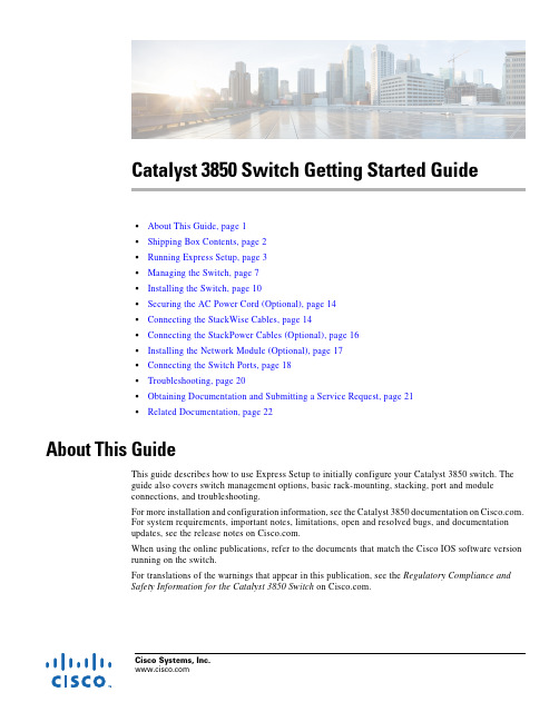
Cisco Systems, Catalyst 3850 Switch Getting Started Guide•About This Guide, page 1•Shipping Box Contents, page 2•Running Express Setup, page 3•Managing the Switch, page 7•Installing the Switch, page 10•Securing the AC Power Cord (Optional), page 14•Connecting the StackWise Cables, page 14•Connecting the StackPower Cables (Optional), page 16•Installing the Network Module (Optional), page 17•Connecting the Switch Ports, page 18•Troubleshooting, page 20•Obtaining Documentation and Submitting a Service Request, page 21•Related Documentation, page 22About This GuideThis guide describes how to use Express Setup to initially configure your Catalyst 3850 switch. The guide also covers switch management options, basic rack-mounting, stacking, port and module connections, and troubleshooting.For more installation and configuration information, see the Catalyst 3850 documentation on . For system requirements, important notes, limitations, open and resolved bugs, and documentation updates, see the release notes on .When using the online publications, refer to the documents that match the Cisco IOS software version running on the switch.For translations of the warnings that appear in this publication, see the Regulatory Compliance and Safety Information for the Catalyst 3850 Switch on .Shipping Box ContentsNoteNoteCatalyst 3850 Switch Getting Started GuideRunning Express Setup NoteNoteCatalyst 3850 Switch Getting Started GuideRunning Express SetupCatalyst 3850 Switch Getting Started GuideRunning Express SetupCatalyst 3850 Switch Getting Started GuideRunning Express SetupStep9Enter this information in the Network Settings fields:Note All entries must be in English letters.•In the Management Interface (VLAN ID) field, the default is 1.Note We recommend that you use the default VLAN value. During Express Setup, VLAN 1 is the only VLAN on the switch. Enter a new VLAN ID only if you want to change the management interface through which youmanage the switch. The VLAN ID range is 1 to 1001.•In the IP Address field, enter the switch IP address.•In the Subnet Mask field, click the drop-down arrow, and select a subnet mask.•In the Default Gateway field, enter the IP address for the default gateway (router).•Enter your password in the Switch Password field. The password can be from 2 to 25 alphanumeric characters, can start with a number, is case sensitive, allows embedded spaces, but does not allow spaces at the beginningor end. In the Confirm Switch Password field, enter your password again.Note You must change the default password, cisco.(Optional) Enter this information in the Ethernet Management Port Settings fields:•In the IP Address field, enter the IP address of the Ethernet management port. In the Subnet Mask field, click the drop-down arrow, and select an IP Subnet Mask.Step10(Optional) You can enter the Optional Settings information now or enter it later by using the Device Manager interface.You can enter other administrative settings in the Optional Settings fields. For example, the optional administrative settings identify and synchronize the switch for enhanced management. NTP automatically synchronizes the switch clock with the network clock. You can manually set the system clock if the switch should have different settings. Step11(Optional) You can select the Advanced Settings tab on the Express Setup window and enter the advanced settings now or enter them later by using the Device Manager interface.•In the Telnet Access field, click Enable if you are going to use Telnet to manage the switch by using the command-line interface (CLI). If you enable Telnet access, you must enter a Telnet password.•In the Telnet Password field, enter a password. The Telnet password can be from 1 to 25 alphanumeric characters, is case sensitive, allows embedded spaces, but does not allow spaces at the beginning or end. In theConfirm Telnet Password field, reenter the Telnet password.•In the SNMP field, click Enable to enable Simple Network Management Protocol (SNMP). Enable SNMP only if you plan to manage switches by using CiscoWorks 2000 or another SNMP-based network-managementsystem.•If you enable SNMP, you must enter a community string in the SNMP Read Community field, the SNMP Write Community field, or both. SNMP community strings authenticate access to MIB objects. Embedded spaces arenot allowed in SNMP community strings. When you set the SNMP read community, you can access SNMPinformation, but you cannot change it. When you set the SNMP write community, you can both access andchange SNMP information.•In the System Contact and System Location fields, enter a contact name and the wiring closet, floor, or building where the switch is located.•(Optional) In the Enable IPv6 field, click Enable to enable IPv6 on the switch. The IPv6 field is enabled by default.Note Enabling IPv6 restarts the switch when you complete Express Setup.Catalyst 3850 Switch Getting Started GuideManaging the SwitchStep12Click Submit to save your changes and to complete the initial setup.After you click Submit:•The switch is configured and exits Express Setup mode.•The browser displays a warning message and tries to connect with the earlier switch IP address. Typically, connectivity between the PC or laptop and the switch is lost because the configured switch IP address is in adifferent subnet from the IP address on the PC or laptop.For more information about Express Setup fields, see the online help for the Express Setup window.Step13Disconnect the switch from the PC or laptop, and install the switch in your network. See the “Installing the Switch”section on page10.Step14If you changed the static IP address on your PC or laptop in Step2, change it to the previously configured static IP address.Step15See the “Managing the Switch” section on page7 for information about configuring and managing the switch. Step16To display Device Manager:1.Start a web browser on your PC or laptop.2.Enter the switch IP address, username, and password assigned in Step9 in the browser, and press Enter.The Device Manager page appears.Troubleshooting:If Device Manager does not appear:•Confirm that the port LED for the switch port connected to your network is green.•Confirm that the PC or laptop that you are using has network connectivity by connecting it to a well-known web server in your network. If there is no network connection, troubleshoot the network settings on the PC or laptop.•Make sure that the switch IP address in the browser is correct.•If the switch IP address in the browser is correct, the switch interface LED is green, and the PC or laptop has network connectivity, continue troubleshooting by reconnecting the PC or laptop to the switch. Configure astatic IP address on the PC or laptop that is in the same subnet as the switch IP address.When the LED on the switch port connected to the PC or laptop is green, reenter the IP address of the switch in a browser to display Device Manager. When Device Manager appears, you can continue with the configuration. Managing the SwitchAfter completing Express Setup and installing the switch in your network, you can use these options forconfiguration:•Device Manager•Cisco Network Assistant•Command-Line Interface•Other Management OptionsCatalyst 3850 Switch Getting Started GuideManaging the SwitchDevice ManagerThe simplest way to manage the switch is by using Device Manager in the switch memory. This is a webinterface that offers quick configuration and monitoring. You can access it through a web browser.Follow these steps:unch a web browser on your PC or laptop.2.Enter the switch IP address in the web browser, and press Enter. The Device Manager page appears.e Device Manager for basic switch configuration and monitoring. Refer to the Device Manageronline help for more information.Configuration WizardThe Configuration Wizard is a Web-based controller user interface (UI) that lets you complete the initialwireless configuration after you configure the IP address, local username, and password or authorizationusing the authentication server. Using the Web UI, you can configure the controller, WLAN, and radiosfor all initial operations, establish management parameters, set security policies, access softwaremanagement commands, configure system logs, and other tasks.For more information on using the Configuration Wizard, see the switch software configuration guideon Cisco Network AssistantCisco Network Assistant is a software program that you download from and run on your PCor laptop. It offers advanced options for configuring and monitoring multiple devices, includingswitches, switch clusters, switch stacks, routers, and access points. Network Assistant is free—there isno charge to download, install, or use it.To use the Cisco Network Assistant:Step1Go to this Web address: /en/US/products/ps5931/index.htmlNote You must be a registered user, but you need no other access privileges.Step2Click the Download Software link, and select the version you want to download.Step3Find the Network Assistant installer.Step4Download the Network Assistant installer, and run it. (You can run it directly from the Web if your browser offers this choice.)Step5When you run the installer, follow the instructions. In the final panel, click Finish.See the Network Assistant online help and the Network Assistant Getting Started Guide for moreinformation.Catalyst 3850 Switch Getting Started GuideManaging the SwitchCommand-Line InterfaceYou can enter Cisco IOS commands and parameters through the CLI by using one of these options:•USB Console Port•RJ-45 Console Port•Ethernet Management PortNote You cannot use the RJ-45 console port and the USB console port at the same time. The USBconsole port takes precedence over the RJ-45 port when both are connected.USB Console PortNote If you are connecting a Microsoft Windows-based PC or laptop to the switch USB console port, installa USB device driver before you connect for the first time. See the Catalyst 3850 Switch HardwareInstallation Guide for instructions.Step1Connect a USB cable to the PC or laptop USB port. Connect the other end of the cable to the mini-B (5-pin-connector) USB port on the switch front panel.Step2Start a terminal-emulation program on the PC or laptop.Step3Configure the PC or laptop terminal emulation software for 9600 baud, 8 data bits, no parity, 1 stop bit, and no flow control.Step4Use the CLI to configure the switch. See the Catalyst 3850 Switch Software Configuration Guide and the Catalyst 3850 Switch Command Reference.RJ-45 Console PortStep1Connect the RJ-45-to-DB-9 adapter cable to the 9-pin serial port on the PC or laptop. Connect the other end of the cable to the switch console port on the rear panel.Step2Start a terminal-emulation program on the PC or laptop.Step3Configure the PC or laptop terminal emulation software for 9600 baud, 8 data bits, no parity, 1 stop bit, and no flow control.Step4Use the CLI to configure the switch. See the Catalyst 3850 Switch Software Configuration Guide and the Catalyst 3850 Switch Command Reference.Catalyst 3850 Switch Getting Started GuideInstalling the SwitchEthernet Management PortStep1Connect a Category 5 Ethernet cable to the PC or laptop Ethernet port. Connect the other end of the cable to the management port on the switch rear panel.Step2Start a Telnet session on the PC or laptop.Step3Enter the switch IP address that you assigned using Express Setup.Step4Use the CLI to configure the switch. See the software configuration guide and the command reference.Other Management OptionsCisco Prime Infrastructure combines the wireless functionality of Cisco Prime Network Control System(NCS) and the wired functionality of Cisco Prime LAN Management Solution (LMS) with applicationperformance monitoring and troubleshooting capabilities of Cisco Prime Assurance Manager. For moreinformation, see the Cisco Prime Infrastructure documentation on .See the “Accessing Help Online” section on page21 for supporting documentation.Installing the SwitchThis section describes basic 19-inch rack-mounting. See the Catalyst 3850 Switch Hardware InstallationGuide for other optional bracket information. The illustrations show the Catalyst 3850-48P-L switch.You can install and connect other Catalyst3850 switches as shown.Equipment That You Need•Phillips screwdriver to rack-mount the switch.Catalyst 3850 Switch Getting Started GuideInstalling the SwitchBefore You BeginBefore installing the switch, verify that these guidelines are met:•Clearance is maintained so that the LEDs on the front panel can be read.•AC power cord reaches from the AC power outlet to the rear-panel connector.•The switch rear panel has a clearance of 4.4 in. (11.1 cm).•If you are installing a 1100-W power supply module, make sure that the switch is rack-mounted before you install it.•Cabling is away from sources of electrical noise, such as radios, power lines, and fluorescentlighting. Make sure the cabling is safely away from other devices that might damage the cables.If needed, allow one RU space between devices to provide room for cabling.•Airflow around the switch and through the vents is unrestricted.•The temperature around the unit does not exceed 113°F (45°C). If the switch is in a closed ormultirack assembly, the temperature might be higher than normal room temperature.•Humidity around the switch does not exceed 95 percent.•Altitude at the installation site is below 10,000 feet.•For 10/100/1000 fixed ports, cables from the switch to connected devices are not longer than328feet (100 meters).•Cooling mechanisms, such as fans and blowers in the switch, can draw dust and other particles causing contaminant buildup inside the chassis, which can result in system malfunction. Install theswitch in an environment as free as possible from dust and foreign conductive material (such asmetal flakes from construction activities).Installation Warning StatementsTranslations of these warning statements appear in the Regulatory Compliance and Safety Informationfor the Catalyst3850 Switch document on .Warning Only trained and qualified personnel should be allowed to install, replace, or service this equipment.Statement 1030Warning To prevent the system from overheating, do not operate it in an area that exceeds the maximum recommended ambient temperature of:113°F (45°C) Statement 1047Warning To prevent airflow restriction, allow clearance around the ventilation openings to be at least:3 in. (7.6 cm) Statement 1076Note The grounding architecture of this product is DC-isolated (DC-I).Installing the SwitchInstalling the Switch WarningSecuring the AC Power Cord (Optional)Connecting the StackWise CablesCautionNoteConnecting the StackPower Cables (Optional)NoteCautionInstalling the Network Module (Optional) NoteConnecting the Switch PortsNoteConnecting the Switch Ports NoteTroubleshootingTroubleshootingThis section includes Express Setup troubleshooting, how to reset the switch, how to access help online,and where to find more information.Express SetupIf Express Setup does not run, or if the Express Setup page does not appear in your browser:Checklist RecommendationDid you verify that POST ran successfully before starting Express Setup?If not, make sure that only the SYST LED and ACTV LED are green before you press the Mode button to enter the Express Setup mode.POST errors are usually fatal. Contact your Cisco technical support representative if your switch fails POST.Did you press the Mode button while the switch was still running POST?If yes, wait until POST completes. Power cycle the switch. Wait until POST completes. Confirm that the SYST LED and ACTV LED are green. Press the Mode button to enter Express Setup mode.Did you try to continue without confirming that the switch was in Express Setup mode?Verify that all LEDs next to the Mode button are green. If not, press and hold the Mode button to enter Express Setup mode.Does your PC or laptop have a static IP address?If yes, change your PC or laptop settings to temporarily use DHCP before connecting it to the switch.Did you connect the Ethernet cable to the console port instead of a10/100/1000 Ethernet port or the management port on the switch?If yes, disconnect the cable from the console port. Connect the cable to an Ethernet port on the switch. Wait 30 seconds before you enter 10.0.0.1 in the browser.Did you wait 30 seconds after you connected the switch and the PC or laptop before you entered the IP address in your browser?If not, wait 30 seconds, reenter 10.0.0.1 in the browser, and press Enter.Did you enter the wrong address in thebrowser, or is there an error message?If yes, reenter 10.0.0.1 in the browser, and press Enter.Catalyst 3850 Switch Getting Started Guide Obtaining Documentation and Submitting a Service RequestResetting the SwitchCaution Resetting the switch reboots the switch.To reset the switch to the factory defaults:Step 1If you are using Cisco IOS XE Release 3.6.0E or later releases, enter the erase startup-config privilegedEXEC command to clear the contents of your startup configuration.If you are using an earlier release, youcan skip this step.Step 2Press and hold the Mode button. The switch LEDs begin blinking after about 3 seconds.Step 3Continue holding down the Mode button. The LEDs stop blinking after 7 more seconds, and then theswitch restarts.Step 4The switch now operates like an unconfigured switch. You can enter the switch IP information by usingExpress Setup as described in the “Running Express Setup” section on page 3.Accessing Help OnlineLook for a solution to your problem in the troubleshooting section of the Catalyst 3850 Switch HardwareInstallation Guide or the Catalyst 3850 Switch Software Configuration Guide on . You canalso access the Cisco Technical Support and Documentation website for a list of known hardwareproblems and extensive troubleshooting documentation.Obtaining Documentation and Submitting a Service RequestFor information on obtaining documentation, submitting a service request, and gathering additionalinformation, see the monthly What’s New in Cisco Product Documentation , which also lists all new andrevised Cisco technical documentation, at:/en/US/docs/general/whatsnew/whatsnew.htmlSubscribe to the What’s New in Cisco Product Documentation as a Really Simple Syndication (RSS) feedand set content to be delivered directly to your desktop using a reader application. The RSS feeds are a freeservice and Cisco currently supports RSS Version 2.0.Related DocumentationRelated DocumentationNote Before installing or upgrading the switch, refer to the switch release notes.•Catalyst 3850 Switch documentation at:/go/cat3850_docs•Cisco SFP and SFP+ modules documentation, including compatibility matrixes at:/en/US/products/hw/modules/ps5455/tsd_products_support_series_home.html•Cisco Validated Designs documents at:/go/designzone•Error Message Decoder, located at:https:///cgi-bin/Support/Errordecoder/index.cgiCisco and the Cisco logo are trademarks or registered trademarks of Cisco and/or its affiliates in the U.S. and other countries. To view a list ofCisco trademarks, go to this URL: /go/trademarks. Third-party trademarks mentioned are the property of their respective owners. Theuse of the word partner does not imply a partnership relationship between Cisco and any other company. (1721R)Any Internet Protocol (IP) addresses used in this document are not intended to be actual addresses. Any examples, command display output, andfigures included in the document are shown for illustrative purposes only. Any use of actual IP addresses in illustrative content is unintentional andcoincidental.© 2013-2014 Cisco Systems, Inc. All rights reserved.Catalyst 3850 Switch Getting Started Guide。
Cisco Catalyst 9120AX Series 企业无线接入点数据手册说明书

Cisco Catalyst 9120AX Series Access PointsData sheet Cisco publicContentsSecure infrastructure 5 Cisco DNA support 5 Product specifications 6 Licensing 22 Warranty information 22 Cisco environmental sustainability 22 Cisco Services 23 Cisco Capital 23 Smart Account 23The Cisco® Catalyst® 9120AX Series Access Points are the next generation of enterprise access points. They are resilient, secure, and intelligent.We are more dependent on our wireless networks than ever before. Additional devices connect to the network every year, and the Cisco Catalyst 9120AX Series Access Points will provide a seamless experience anywhere for everyone. Going beyond the Wi-Fi 6 (802.11ax) standard, the 9120AX Series provides integrated security, resiliency, and operational flexibility as well as increased network intelligence.Extendi ng Cisco’s intent-based network and perfect for networks of all sizes, the Cisco Catalyst 9120AX Series scales to the growing demands of IoT while fully supporting the latest innovations and new technologies. Not only that, but the 9120AX Series is a leader in performance, security, and analytics.The Cisco Catalyst 9120AX Series Access Points, paired with Cisco DNA, are enterprise-class products that will address your current and future needs. These access points are the first step in updating your network so that you can take better advantage of all of the features and benefits that Wi-Fi 6 provides.Table 1.Features and benefitsFor more details about Wi-Fi 6, see Cisco’s technical white paper on Wi-Fi 6.For more details about C9120 feature support, see Cisco's Feature Matrix.Secure infrastructureTrustworthy systems built with Cisco Trust Anchor Technologies provide a highly secure foundation for Cisco products. With the Cisco Catalyst 9100 Access Points, these technologies enable hardware and software authenticity assurance for supply chain trust and strong mitigation against man-in-the-middle attacks that compromise software and firmware. Trust Anchor capabilities include:●Image signing●Secure Boot●Cisco Trust Anchor moduleCisco DNA supportPairing the Cisco Catalyst 9120AX Series Access Points with Cisco DNA allows for a total network transformation. Cisco DNA allows you to truly understand your network with real-time analytics, quickly detect and contain security threats, and easily provide networkwide consistency through automation and virtualization. The 9120AX Series supports Software-Defined Access (SD-Access), Cisco’s leading enterprise architecture. Working together, the Cisco Catalyst 9120AX Series and Cisco DNA offer such features as:●Cisco DNA Spaces●Cisco Identity Services Engine●Cisco DNA Analytics and AssuranceThe result? Your network stays relevant, becomes digital ready, and is the lifeblood of your organization. Note: For information about Cisco Networking, refer to the Cisco Networking Solution Overview.Product specifications Table 2.SpecificationsFigure 1.Antenna radiation patternsNote: For information about feature support, refer to the Cisco Catalyst 9100 Release Notes.LicensingFor information about licensing and packaging, refer to Cisco Licensing.Warranty informationThe Cisco Catalyst 9120AX Series Access Points come with a limited lifetime warranty that provides full warranty coverage of the hardware for as long as the original end user continues to own or use the product. The warranty includes 10-day advance hardware replacement and ensures that software media are defect-free for 90 days. For more details, visit https:///go/warranty.Cisco environmental sustainabilityInformation about Cisco’s environmental sustainability policies and initiatives for our products, solutions, operations, and extended operations or supply chain is provided in the “Environment Sustainability” section of Cisco’s Corporate Social Responsibility (CSR) Report.Reference links to information are belowInformation on product material content laws and regulations: Materials.Information on electronic waste laws and regulations, including products, batteries, and packaging:WEEE compliance.Cisco does not represent, warrant, or guarantee that it is complete, accurate, or up to date. This information is subject to change without notice.Cisco ServicesWith Cisco Services, you can achieve infrastructure excellence faster with less risk. From an initial WLAN readiness assessment to implementation, full solution support, and in-depth training, our services for the Cisco Catalyst 9120AX Series provide expert guidance to help you successfully plan, deploy, manage, and support your new access points. With unmatched networking expertise, best practices, and innovative tools, Cisco Services can help you reduce overall upgrade, refresh, and migration costs as you introduce new hardware, software, and protocols into the network. With a comprehensive lifecycle of services, Cisco experts will help you minimize disruption and improve operational efficiency to extract maximum value from your Cisco DNA-ready infrastructure.Cisco CapitalFlexible payment solutions to help you achieve your objectivesCisco Capital makes it easier to get the right technology to achieve your objectives, enable business transformation and help you stay competitive. We can help you reduce the total cost of ownership, conserve capital, and accelerate growth. In more than 100 countries, our flexible payment solutions can help you acquire hardware, software, services and complementary third-party equipment in easy, predictable payments. Learn more.Smart AccountCreating a Smart Account by using the Cisco Smart Software Manager (SSM) enables you to order devices and licensing packages and also manage your software licenses from a centralized website. For more information on Smart Accounts, refer to https:///go/smartaccounts.Printed in USA C78-742115-10 08/21。
Cisco Catalyst 3850 系列交换机产品资料
24 端口 SFP 交换机
12 端口 SFP+ 交换机
PWR-C1-350WAC
-
24 端口 SFP+ 交换机
PWR-C1-715WAC
全球 [更改] 登录 帐户 注册
我的思科
Cisco Catalyst 3850 系列交换机
Cisco Catalyst 3850 系列交换机产品资料
主页 o 产品和服务
寻求帮助
交换机
联系我们
CISCO CATALYST 3850 系 电子邮件 | 申请报价
列交换机 产品资料和文献
查找本地经销商
默认电源 PWR-C1-350WAC
可用 PoE 功率 -
PWR-C1-715WAC
435W
PWR-C1-1100WAC PWR-C1-1100WAC
800W 800W
PWR-C1-1100WAC PWR-C1-1100WAC
580W 630W
12 端口 SFP 交换机
PWR-C1-350WAC
-
产品概述
● 全面的无线控制器功能,包括: ◦ 每交换机最高 40G 的无线容量(48 端口 RJ45 型号) ◦ 每个交换实体上支持最高 100 个接入点和 2000 个无线客户端(交换机或堆叠)
● 24 和 48 个 10/100/1000Mbps 数据 PoE+ 和 Cisco UPOE 型号,支持高能效以太网 (EEE) ● 24 和 48 个 100Mbps/1/2.5/5/10 Gbps Cisco UPOE 型号,支持高能效以太网 (EEE) ● 12 和 24 端口 1 千兆位以太网 SFP 型号 ● 12 和 24 端口 1 千兆位以太网 SFP+ 型号 ● 48 端口 1/10 千兆位以太网 SFP+ 型号,带有 4 个固定 40 千兆位以太网 QSFP+ 上行链路 ● Cisco StackWise-480 技术提供了可扩展性和弹性,具备 480 Gbps 堆叠吞吐量[1] ● Cisco StackPower™ 技术提供了与其他堆叠成员的电源堆叠功能,实现电源冗余 1 ● 五个可选上行链路模块[2],支持 4 x 千兆位以太网、2 x 万兆位以太网、4 x 万兆位以太网[3]、8 x 万兆位以太网 4, 或者 2 x 40 千兆
思科3750_3550_2900系列交换机诊断(上)
Session Number Presentation_ID © 2005 Cisco Systems, Inc. All rights reserved.
QQ:505836736
Cisco Confidential
3
互联神州思科专业技术培训
SESSION RST-3041
崔俊杰 TAC China
成都互联神州思科专业技术培训学校培训网站:
Session Number Presentation_ID © 2005 Cisco Systems, Inc. All rights reserved.
QQ:505836736
Runts 0 0
Giants 0 0
InMcastPkts 67463 OutMcastPkts 0 0
InBcastPkts 453 OutBcastPkts 0 0
2950# show interface fastEthernet 0/1 FastEthernet0/1 is up, line protocol is up (connected) Hardware is Fast Ethernet, address is 0005.7428.2901 (bia 0005.7428.2901) MTU 1500 bytes, BW 100000 Kbit, DLY 1000 usec, reliability 255/255, txload 1/255, rxload 1/255 etc...
Session Number Presentation_ID © 2005 Cisco Systems, Inc. All rights reserved.
校园网实施方案设计-思科交换机路由器配置命令

校园⽹实施⽅案设计-思科交换机路由器配置命令xxx xx x x⼤学毕业论⽂(设计)课题名称:校园⽹络实施⽅案年级专业:级⽹络技术学号:xxxxxxxxxxxx姓名:董xx指导教师:雷年⽉⽇xxxxxxx⼤学毕业论⽂(设计)任务书2013年10 ⽉12 ⽇摘要随着⽹络建设的逐步普及,⼤学⾼校局域⽹络的建设是⾼校向⾼⽔平、研究性⼤学跨进的必然选择,⾼校校园⽹⽹络系统是⼀个⾮常庞⼤⽽复杂的系统,它不仅为⾼校的发展、综合信息管理和办公⾃动化等⼀系列应⽤提供基本操作平台,⽽且,能够使教育、教学、科研三位⼀体,提⾼教育教学质量。
⽽校园⽹⽹络建设中主要应⽤了⽹络技术中的重要分⽀局域⽹技术来建设与管理的,因此本毕业设计课题将主要以校园局域⽹络建设过程可能⽤到的各种技术及实施⽅案为设计⽅向,为校园⽹的建设提供理论依据和实践指导。
⾼校校园⽹的⽹络建设与⽹络技术发展⼏乎是同步进⾏的。
⾼校不仅承担着教书育⼈的⼯作,更承担着部分国家级的科研任务,同时考虑未来⼏年⽹络平台的发展趋势, 为了充分满⾜⾼校⾻⼲⽹对⾼速,智能,安全,认证计费等的需求,可以利⽤万兆以太⽹的校园⽹组⽹技术。
构建校园⽹⾻⼲⽹,实现各个分校区和本部之间的连接,以及实现端到端的以太⽹访问,提⾼了传输的效率,有效地保证了远程多媒体教学、数字图书馆等业务的开展。
【关键词】校园⽹;⽹络⼯程;⽹络管理;⽹络设备;组建;实施AbstractWith the gradually popularization of network construction, the construction of local area network at colleges and universities in is to a high level of colleges and universities and research universities got inevitably choice, the university campus network system is a very large and complex system, it not only to the development of colleges and universities, comprehensive information management and office automation and so on a series of applied to provide basic operation platform, and can make education, teaching and scientific research of the trinity, improve the teaching quality of education. And the network technology has been applied in the construction of campus network important branch in the local area network technology to the construction and management, therefore this graduation design topic will mainly take the campus local area network construction process may be used various technique and implementation plan for design direction, provide theoretical basis and practical guidance for the construction of campus network. University campus network construction and network technology development is almost simultaneous. Not only bear the teaching work in colleges and universities, bear the part of the national scientific research tasks, at the same time, considering the future development trend of the network platform, in order to fully satisfy the backbone to high speed, intelligence, safety, certification billing requirements, such as campus network can use Wan Zhao Ethernet network technology. Construction of campus network backbone, the realization of each branch area and the connection between the department, and implement end-to-end Ethernet access, improve the efficiency of the transmission, effectively guarantee the distance multimedia teaching, digital library and other business.Keywords:Campus network; Network engineering; Network management;The network equipment;To form a; The implementation of⽬录引⾔ (1)第1章需求分析 (2)1.1需求分析的任务 (2)1.1.1校园⽹建设的原则 (2)1.1.2背景及意义 (2)1.2校园⽹⽤户需求分析 (4)1.3校区⽹络的设计⽬标: (4)1.4系统设计指导思想 (4)1.5组⽹技术选择 (5)1.6⽹络产品选型 (6)第2章校园⽹络具体设计⽅案及分析 (8)2.1⽹络的分层设计原则 (8)2.1.1核⼼层(Core Layer) (8)2.1.2汇聚层(Convergence layer) (8)2.1.3接⼊层(Access Layer) (8)2.2⾼性能的⽹络设计 (9)2.3可靠的⽹络安全设计 (9)2.4具体⽅案设计 (9)2.5VLAN的设计: (10)2.5.1⽤户VLAN的设计: (10)2.5.2设备管理VLAN设计: (11)2.6IP地址的设计: (11)2.6.1⽤户IP地址的设计: (11)2.6.2设备管理IP地址的设计: (11)2.7整个具体⽹络拓扑图设计图 (12)第3章⽹络设备的配置 (13)3.1配置家属区接⼊1交换机 (13)3.2配置家属区接⼊2交换机 (13)3.3家属区汇聚 (14)3.4核⼼交换机1 (15)3.5核⼼交换机2 (16)3.6边界路由器配置 (17)结束语 (19)致 (20)参考⽂献 (21)引⾔科学技术的发展⽇新⽉异,⽹络技术已经成为现代信息技术的主流,⼈们对⽹络的认识也随着⽹络的应⽤的逐渐普及⽽迅速改变。
数据系统有限公司CISCOMDS9124产品促销方案(word1页)
Description
QTY
特价促销
DS-C9124-K9
Cisco MDS 9124 24端口多层光纤阵列交换机,带8个4-Gbps有效端口,VSAN,PortChannels和思科光纤阵列管理器;支持冗余电源(300W AC)
1
DS-SFP-FC4G-SW=
Cisco MDS 9000系列4/2/1-Gbps光纤通道—SW,SFP,LC,备件
此次促销奖励活动最终解释权归华商达公司所有。
16
M9124PL8-4G=
Cisco MDS 9124按需端口激活许可证;激活增量为5*8*NBD
1
Price
¥174355
¥45188
促销活动期间,奖励两台起算,500*2=1000元,发购物卡或加油卡;4台2000元,PSP一部;6台3000元,手机一部;8台4000元,数码相机一部;10台5000元,等值PDA或笔记本电脑一台。
CISCO MDS 9124产品促销方案
鉴于CISCO存储产品现在初期推广阶段,我们特针对CISCO MDS 9124 16口交换机做一期特价让利促销,以此考察代理及用户价值所在,时间为从现在起至10月底结束,
带一年CISCOSMARTnet5*8*NBD服务产品销售价格为:¥45188。
标准配置价格为:
PC机与3850示波器通信程序的框架设计
PC机与3850示波器通信程序的框架设计
吴剑峰;汪敏
【期刊名称】《河南工业大学学报(社会科学版)》
【年(卷),期】2004(020)004
【摘要】串行通信应用广泛.文章用VC++实现PC机与3850数字存储示波器的在Windows 系统下的串行通讯,并给出了通讯程序框架.
【总页数】2页(P6-7)
【作者】吴剑峰;汪敏
【作者单位】河南工业大学,河南,郑州,450007;河南工业大学,河南,郑州,450007【正文语种】中文
【中图分类】TP391.6
【相关文献】
1.基于MSComm的PC机与单片机串行通信程序设计 [J], 邱育桥
2.基于VB的单片机与PC机串行通信程序设计 [J], 罗红萍;彭云柯
3.多总线控制系统通用化通信程序框架设计 [J], 兰京川;陈光(禹)
4.3850汽车专用示波器 [J],
5.基于C++ Builder的PC机与单片机通信程序设计 [J], 王宜结;闻国才
因版权原因,仅展示原文概要,查看原文内容请购买。
Cisco Catalyst 3850 系列交换机
产品手册Cisco Catalyst 3850 系列交换机Cisco® Catalyst® 3850 系列是下一代企业级堆叠式访问层交换机,可在一个单一平台上完全融合有线与无线方式。
思科的新统一访问数据平台 (UADP) 应用专用集成电路(ASIC) 为交换机提供电力,并可实现统一的有线与无线策略实施、应用可见性和应用优化。
此融合建立在新的改进的 Cisco StackWise-480 的恢复能力上。
Cisco Catalyst 3850 系列交换机支持全面的 IEEE 802.3at 增强型以太网供电 (PoE+)、模块化和现场可换网络模块、冗余风扇和电源。
产品概述●无线控制器功能与以下功能集成:◦每个交换机最高 40G 的无线容量(48 端口型号)◦每个交换实体(交换机或堆叠)支持多达 50 个访问点和 2000 个无线客户端●24 和 48 10/100/1000 数据和 PoE+ 型号,带节能以太网 (EEE)◦Cisco StackWise-480 技术具有可扩展性和恢复能力,并提供 480 Gbps 的堆叠吞吐量◦Cisco StackPower 技术为堆叠成员提供电源堆叠,以实现电源冗余◦ 3 个可选上行链路模块,带 4 x 千兆位以太网、2 x 万兆位以太网或 4 x 万兆位以太网端口◦双冗余模块化电源和 3 个模块化风扇提供冗余◦完全的 802.3at (PoE+),所有端口均提供 30W 功率,1 个机架单元 (RU) 外形●软件支持 IPv4 和 IPv6 路由、组播路由、模块化服务质量 (QoS)、Flexible NetFlow (FNF) 版本 9 和增强型安全功能●单个跨所有许可级别的通用思科 IOS®软件映像,为接入点和软件功能提供简单的升级路径●增强型有限终身保修 (E-LLW)、下一工作日 (NBD) 硬件备件先行更换和 90 天思科技术支持中心 (TAC) 支持交换机配置所有交换机都随附四种电源之一(350W 交流电源、715W 交流电源、1100W 交流电源或 440W 直流电源)。
MDS_9124光纤交换机配置手册
Cisco MDS 9124交换机配置手册北京众志和达信息技术有限公司2010年12月版本控制目录版本控制 (2)1 MDS 初始化配置 (4)1.1配置串口登录 (4)1.2 License 配置 (4)1.3配置管理地址 (6)1.4配置telnet登录 (6)1.5初始化端口类型 (7)1.6配置FC ID (8)2配置MDS Zone (10)2.1配置VSAN (10)2.2配置Domain IDs (11)2.4配置Zone (13)2.5创建设备别名 (14)2.3配置Zoneset (15)2.6激活Zoneset (16)2.7保存配置 (16)2.8实例演示 (17)3 MDS 维护 (18)3.1常用命令查询 (18)3.2使用默认zone (19)附件:配置NPV (20)Cisco MDS 9000系列交换机的管理和配置可以使用CLI和基于GUI的Cisco MDS 9000 Fabric Manager两种方式进行管理。
本文主要介绍了Cisco MDS 9124交换机在CLI方式下配置Zone的方法和步骤,该方法也同样适用于使用Cisco MDS NX-OS Release 4.1版本的其它9000系列交换机。
1 MDS 初始化配置1.1配置串口登录Cisco MDS 9000系列交换机在默认没有配置的情况下,只能通过串口进行参数设置如右图所示:初次启动并进入MDS 交换机之后,会出现“Would you liketo enter the basic configuration dialog (yes/no): yes”提示,这里表示是否需要启动向导模式配置该交换机,此处输入“NO”。
然后根据提示输入管理员密码。
1.2 License 配置Cisco MDS 交换机不同于Brocade交换机之处为Cisco MDS 交换机可以单独为某个指定的端口配置license,暂时不使用的端口可以释放端口的license。
- 1、下载文档前请自行甄别文档内容的完整性,平台不提供额外的编辑、内容补充、找答案等附加服务。
- 2、"仅部分预览"的文档,不可在线预览部分如存在完整性等问题,可反馈申请退款(可完整预览的文档不适用该条件!)。
- 3、如文档侵犯您的权益,请联系客服反馈,我们会尽快为您处理(人工客服工作时间:9:00-18:30)。
XX大学CISCO MDS9124和BRACODE 3850级联实施目录1.实施前准备工作 (2)a.CISCO MDS9124上架安装调试 (2)b.收集两台BRACODE 3850信息 (2)1).光纤交换机基本配置信息 (2)2).交换机端口分配 (2)3).交换机Zone划分 (3)c.收集两台EMC9124A信息 (5)1).光纤交换机基本配置信息 (5)2) 交换机端口分配 (6)3) 交换机Zone划分 (6)d.把端口zone转化成wwn zone方式 (7)2.MDS9124和BRACODE 3850实施环境要求 (7)3.MDS9124和BRACODE 3850级联实施 (8)a.配置异构交换机平台协同工作模式 (8)b.重新划分zone (11)4.MDS9124(北校区)和EMC9124(南校区)实施环境要求 (12)5.MDS9124(北校区)和EMC9124(南校区)实施级联实施 (13)a.配置南校区EMC9124 (13)c. 配置北校区的MDS9124 (14)6.最终的SAN 拓扑图 (15)附录: (15)a.MDS9124常用show (15)1)查看running (15)2)查看端口对应的HBA卡的WWN (20)b.在BRACODE 3850查看命令 (20).1) 查看SWITCH和端口连接的HBA卡的WWN (20)2) 查看ZONE和CFG信息 (21)1.实施前准备工作a.CISCO MDS9124上架安装调试b.收集两台BRACODE 3850信息1).光纤交换机基本配置信息2).交换机端口分配3).交换机Zone划分2. 192.168.0.19c.收集两台EMC9124A信息1).光纤交换机基本配置信息2) 交换机端口分配3) 交换机Zone划分优化原来的ZONE,把连接NS20的端口fc1/1和fc1/2并到一块与主机的HBA,重新做成一个ZONE.,如果ZONE如下:zone name c3z01 vsan 2member pwwn 50:06:01:60:41:e0:94:5emember pwwn 50:06:01:68:41:e0:94:5emember pwwn 21:00:00:1b:32:02:67:70zone name c3z02 vsan 2member pwwn 50:06:01:60:41:e0:94:5emember pwwn 50:06:01:68:41:e0:94:5emember pwwn 21:00:00:1b:32:08:1d:f6zone name c3z03 vsan 2member pwwn 50:06:01:60:41:e0:94:5emember pwwn 50:06:01:68:41:e0:94:5emember pwwn 21:00:00:e0:8b:01:bd:01d.把端口zone转化成wwn zone方式看上面的交换机Zone划分表,已完成2.MDS9124和BRACODE 3850实施环境要求a.关闭所有连接在两台bracode 3850的SAN SWITCH所在主机上的应用,如何是linux或unix要把相关的文件系统UMOUNTb.把两台bracode 3850的配置信息保存在PC机上做备份用configupload 传到PC上。
3.MDS9124和BRACODE 3850级联实施a.配置异构交换机平台协同工作模式Cisco 9124配置过程激活端口switch# config tEnter configuration commands, one per line. End with CNTL/Z.switch(config)#interface fc1/1-24switch(config-if)# no shutdownswitch(config-if)# end创建vsan 2mds9124-2# config tEnter configuration commands, one per line. End with CNTL/Z.mds9124-2(config)# vsan databasemds9124-2(config-vsan-db)# vsan 2 name wzdxmds9124-2(config-vsan-db)# vsan 2 interface fc1/1-16mds9124-2(config-vsan-db)# end配置交换机协同工作模式switch# config tEnter configuration commands, one per line. End with CNTL/Z.switch(config)# vsan databaseswitch(config-vsan-db)# vsan 1 interopswitch(config-vsan-db)# end配置domain IDswitch# config tEnter configuration commands, one per line. End with CNTL/Z.switch(config)# fcdomain domain 100 preferred vsan 1switch(config)# end激活VSANswitch# config tEnter configuration commands, one per line. End with CNTL/Z.switch(config)# vsan databaseswitch(config-vsan-db)# vsan 1 suspendswitch(config-vsan-db)# no vsan 1 suspendswitch(config-vsan-db)# end察看修改之后的系统配置信息switch# show running察看端口连接状态信息switch# show interface briefmds9124-2# show interface brief-------------------------------------------------------------------------------Interface Vsan Admin Admin Status SFP Oper Oper PortMode Trunk Mode Speed Channe Mode (Gbps)-------------------------------------------------------------------------------fc1/1 2 auto on up swl F 4 --fc1/2 2 auto on up swl F 4 --fc1/3 2 auto on up swl E 2 --fc1/4 2 auto on notConnected swl -- --fc1/5 2 auto on notConnected swl -- --fc1/6 2 auto on notConnected swl -- --fc1/7 2 auto on notConnected swl -- --fc1/8 2 auto on notConnected swl -- --fc1/9 2 auto on notConnected swl -- --fc1/10 2 auto on notConnected swl -- --fc1/11 2 auto on notConnected swl -- --fc1/12 2 auto on notConnected swl -- --fc1/13 2 auto on notConnected swl -- --fc1/14 2 auto on notConnected swl -- --fc1/15 2 auto on up swl F 4 --fc1/16 2 auto on notConnected swl -- -- BRACODE 3850光纤交换机配置禁止交换机brocadessm:USERID> switchdisable修改Domain IDswd77:admin> switchdisableswd77:admin> configureConfigure...Fabric parameters (yes, y, no, n): [no] yDomain: (1..239) [1] 101R_A_TOV: (4000..120000) [10000]E_D_TOV: (1000..5000) [2000]WAN_TOV: (0..30000) [0]MAX_HOPS: (7..19) [7]Data field size: (256..2112) [2112]Sequence Level Switching: (0..1) [0]Disable Device Probing: (0..1) [0]Suppress Class F Traffic: (0..1) [0]Switch PID Format: (1..2) [1]Per-frame Route Priority: (0..1) [0]Long Distance Fabric: (0..1) [0]BB credit: (1..27) [16]Insistent Domain ID Mode (yes, y, no, n): [no]Virtual Channel parameters (yes, y, no, n): [no]F-Port login parameters (yes, y, no, n): [no]Zoning Operation parameters (yes, y, no, n): [no]RSCN Transmission Mode (yes, y, no, n): [no]Arbitrated Loop parameters (yes, y, no, n): [no]System services (yes, y, no, n): [no]Portlog events enable (yes, y, no, n): [no]ssl attributes (yes, y, no, n): [no]snmp attributes (yes, y, no, n): [no]rpcd attributes (yes, y, no, n): [no]cfgload attributes (yes, y, no, n): [no]webtools attributes (yes, y, no, n): [no]System (yes, y, no, n): [no]WARNING: The domain ID will be changed. The port level zoning may be affectedswd77:admin> msPlMgmtDeactivateThe switch must be enabled in order to disable Platform Servicesswd77:admin> switchenable修改协同工作模式swd77:admin> interopmode 1Please disable switch before changing the interop mode.swd77:admin> switchdisableswd77:admin> interopmode 1Please make sure no AD is configuredSwitch interop mode is not supported in AD configured mode.Please run ad --clear and ad --apply to clear AD configurations.Please make sure the MS Platform service is disabled.Please run "msPlMgmtDeactivate" command to disable the Platform service.The switch effective configuration will be lost when the operating mode is changed; do you want to continue? (yes, y, no, n): [no] yesInteropmode is enabledNote: It is recommended that you reboot this switch for the new change to take effect.重新引导交换机swd77:admin> fastboot激活交换机brocadessm:USERID> switchenable察看修改配置之后的交换机状态swd77:admin> switchshowswitchName: swd77switchType: 26.2switchState: OnlineswitchMode: InteropswitchRole: PrincipalswitchDomain: 101 (unconfirmed)switchId: fffc65switchWwn: 10:00:00:05:1e:34:1b:f1zoning: OFFswitchBeacon: OFFArea Port Media Speed State Proto=====================================0 0 id N2 In_Sync Disabled (Switch not ready for F or L ports)1 1 id N2 In_Sync Disabled (Switch not ready for F or L ports)2 2 id N2 Online E-Port 20:02:00:0d:ec:8f:45:81 "" (upstream)3 3 id N2 No_Sync Disabled (Switch not ready for F or L ports)4 4 id N2 In_Sync Disabled (Switch not ready for F or L ports)5 5 id N2 In_Sync Disabled (Switch not ready for F or L ports)6 6 id N2 In_Sync Disabled (Switch not ready for F or L ports)7 7 id AN No_Sync8 8 id N2 No_Sync Disabled (Switch not ready for F or L ports)9 9 id AN No_Sync10 10 id N2 No_Sync Disabled (Switch not ready for F or L ports)11 11 id AN No_Sync12 12 id N2 No_Sync Disabled (Switch not ready for F or L ports)13 13 id N2 No_Sync Disabled (Switch not ready for F or L ports)14 14 id N2 No_Sync Disabled (Switch not ready for F or L ports)15 15 id N2 No_Sync Disabled (Switch not ready for F or L ports)b.重新划分zone1).在原来的BRACODE上创建ZONE,把原来port zone改成wwn zone清空BRACODE的配置SWD77:admin> cfgclearDo you really want to clear all configurations? (yes, y, no, n): [no] yes Clearing All zoning configurations...SWD77:admin> cfgshowDefined configuration:no configuration definedEffective configuration:no configuration in effect在MDS9124上增加ZONEmds9124-1(config)# zone name b1z01 vsan 2mds9124-1(config-zone)# member pwwn 50:06:0e:80:00:c4:17:90mds9124-1(config-zone)# member pwwn 50:06:0e:80:00:c4:17:94mds9124-1(config-zone)# member pwwn 50:01:10:a0:00:85:66:ecmds9124-1(config-zone)# exit照着上面的zone表,进行增加zone把ZONE添加到配置ZONESET里mds9124-1(config)# zoneset name c1zone vsan 2mds9124-1(config-zoneset)# member b1z01mds9124-1(config-zoneset)# member b1z02mds9124-1(config-zoneset)# member b1z03mds9124-1(config-zoneset)# member b1z04mds9124-1(config-zoneset)# member b1z05mds9124-1(config-zoneset)# member b1z06mds9124-1(config-zoneset)# member b1z07mds9124-1(config-zoneset)# member b1z08mds9124-1(config-zoneset)# member b1z09mds9124-1(config-zoneset)# member b1z10mds9124-1(config-zoneset)# member b1z11mds9124-1(config-zoneset)# exit激活配置mds9124-1(config)# zoneset activate name c1zone vsan 2Zoneset activation initiated. check zone status查看当前的配置mds9124-1# show run2).在BRACODE3850查看zone信息swd77:admin> cfgshow在这里能看到在bracode 配置的zone信息4.MDS9124(北校区)和EMC9124(南校区)实施环境要求a.关闭所有连接在SAN SWITCH所在主机上的应用,如何是linux或unix要把相关的文件系统UMOUNTb.把MDS9124的配置信息保存在PC机上做备份用cpoy run ftp: 传到PC上。