电动助力转向系统的开发研究
汽车电动助力转向系统设计 毕业论文

汽车电动助力转向系统设计毕业论文本章主要介绍汽车电动助力转向系统设计的背景和意义,以及论文的目的和结构安排。
汽车转向系统是车辆控制的重要组成部分,它直接影响着驾驶员的操控感受和行车安全性。
随着科技的发展,传统的液压助力转向系统逐渐被电动助力转向系统所取代。
电动助力转向系统通过电力传动装置提供操控力,相较于液压助力转向系统具有更高的效率、更好的节能性和可靠性。
本文的目的是设计一种可靠、高效的汽车电动助力转向系统。
在研究的基础上,将重点关注系统的结构设计、控制算法优化、故障诊断等方面。
通过对系统的设计和优化,可以提高汽车的操控性和安全性。
本文结构安排如下:第二章将介绍汽车电动助力转向系统的背景与发展;第三章将详细阐述系统的设计原理与结构;第四章将重点探讨控制算法的优化与实现;第五章将研究系统的故障诊断方法与技术;最后,第六章将总结全文,并提出进一步研究的展望。
通过本文的研究和实践,相信可以为汽车电动助力转向系统的设计与优化提供一定的参考和借鉴,推动汽车技术的发展与进步。
在这一部分,我们将对汽车电动助力转向系统设计相关的文献进行综述。
我们将总结已有的研究成果,以及当前存在的问题。
具体内容}本文详细介绍了汽车电动助力转向系统设计的方法和步骤,涵盖了传感器选择、电机控制、系统优化等方面。
传感器选择在汽车电动助力转向系统设计中,选择合适的传感器是至关重要的。
传感器可以检测车轮的转向角度、转向速度以及转向力等参数,为后续的电机控制提供必要的数据支持。
常见的传感器包括转向角度传感器、转向速度传感器和转向力传感器。
在选择传感器时,需考虑其精度、响应速度和可靠性等因素,并确保其能与电机控制系统良好地配合。
电机控制在汽车电动助力转向系统中,电机控制是实现转向功能的核心部分。
电机控制系统通过接收传感器提供的数据,计算并控制电机的输出力矩,从而实现汽车的转向功能。
电机控制的关键是控制算法的设计和实现。
常见的电机控制方法有PID控制、模糊控制和神经网络控制等。
乘用车电动助力转向系统匹配与仿真分析的开题报告

乘用车电动助力转向系统匹配与仿真分析的开题报告一、研究背景及意义随着电动汽车的不断普及和推广,电动助力转向系统作为电动汽车控制系统的一个重要组成部分,正在得到越来越广泛的应用。
因此,研究乘用车电动助力转向系统的匹配与仿真分析,具有重要的实践意义。
乘用车电动助力转向系统的匹配可以帮助汽车制造商在生产过程中合理选择电动助力转向系统的参数和控制策略,从而使汽车的转向性能更加稳定、灵活和安全。
同时,对电动助力转向系统的仿真分析可以帮助汽车制造商在生产过程中优化系统设计,降低成本,提高产品质量和性能。
二、研究目标和研究内容1. 研究目标本研究旨在探究乘用车电动助力转向系统的匹配问题,并利用仿真分析方法对系统性能进行评估,为汽车制造商提供优化电动助力转向系统设计的参考。
2. 研究内容(1)乘用车电动助力转向系统的构成和原理(2)电动助力转向系统匹配的基本原则和方法(3)电动助力转向系统的建模和仿真分析(4)验证仿真结果与实际测试结果的一致性三、研究方法和技术路线本研究采用文献研究、理论分析和仿真分析相结合的研究方法,具体技术路线如下:(1)文献研究和理论分析:查阅相关文献资料,了解乘用车电动助力转向系统的构成、工作原理和匹配原则等相关理论知识。
(2)电动助力转向系统的建模和仿真分析:利用MATLAB/Simulink 等软件工具,对电动助力转向系统进行建模和仿真分析,并进行系统参数优化和性能评估。
(3)验证仿真结果与实际测试结果的一致性:利用实车测试等方法,对仿真结果进行验证和对比分析,评估仿真模型的准确性和可靠性。
四、预期成果和应用前景本研究的预期成果包括:(1)掌握乘用车电动助力转向系统的构成、工作原理和匹配方法等相关理论知识。
(2)建立乘用车电动助力转向系统的仿真模型,并对系统进行参数优化和性能评估。
(3)验证仿真结果与实际测试结果的一致性,评估仿真模型的准确性和可靠性。
(4)为汽车制造商提供优化电动助力转向系统设计的参考,提高产品质量和性能。
汽车电动助力转向系统的研究大学毕业论文外文文献翻译及原文
毕业设计(论文)外文文献翻译文献、资料中文题目:汽车电动助力转向系统的研究文献、资料英文题目:The auto electric power steering system research 文献、资料来源:文献、资料发表(出版)日期:院(部):专业:班级:姓名:学号:指导教师:翻译日期:2017.02.14英文原文The auto electric power steering system researchAlong with automobile electronic technology swift and violent development, the people also day by day enhance to the motor turning handling quality request. The motor turning system hanged, the hydraulic pressure boost from the traditional machinery changes (Hydraulic Power Steering, is called HPS), the electrically controlled hydraulic pressure boost changes (Electronic Hydraulic Power Steering, is called EHPS), develops the electrically operated boost steering system (Electronic Power Steering, is called EPS), finally also will transit to the line controls the steering system (Steer By Wire, will be called SBW).The machinery steering system is refers by pilot's physical strength achievement changes the energy, in which all power transmission all is mechanical, the automobile changes the movement is operates the steering wheel by the pilot, transmits through the diverter and a series of members changes the wheel to realize. The mechanical steering system by changes the control mechanism, the diverter and major part changes the gearing 3 to be composed.Usually may divide into according to the mechanical diverter form: The gear rack type, follows round the world -like, the worm bearing adjuster hoop type, the worm bearing adjuster refers sells the type. Is the gear rack type and follows using the broadest two kinds round the world -like (uses in needing time big steering force).In follows round the world -like in the diverter, the input changes the circle and the output steering arm pivot angle is proportional; In the gear rack type diverter, the input changes the turn and the output rack displacement is proportional. Follows round the world -like the diverter because is the rolling friction form, thus the transmission efficiency is very high, the ease of operation also the service life are long, moreover bearing capacity, therefore widely applies on the truck. The gear rack type diverter with follows round the world -like compares, the most major characteristic is the rigidity is big, the structure compact weight is light, also the cost is low. Because this way passes on easily by the wheel the reacting force to the steering wheel, therefore has to the pavement behavior response keen merit, but simultaneously also easy to have phenomena and so on goon and oscillation, also its load bearing efficiency relative weak, therefore mainly applies on the compact car and the pickup truck, at present the majority of low end passenger vehicle uses is the gear rack type machinery steering system.Along with the vehicles carrying capacity increase as well as the people to the vehicles handling quality request enhancement, the simple mechanical type steering system were already unable to meet the needs, the power steering system arise at the historic moment, it could rotate the steering wheel while the pilot to provide the boost, the power steering system divides into thehydraulic pressure steering system and the electrically operated steering system 2kinds.Hydraulic pressure steering system is at present uses the most widespread steering system.The hydraulic pressure steering system increased the hydraulic system in the mechanical system foundation, including hydraulic pump, V shape band pulley, drill tubing, feed installment, boost installment and control valve. It with the aid of in the motor car engine power actuation hydraulic pump, the air compressor and the generator and so on, by the fluid strength, the physical strength or the electric power increases the pilot to operate the strength which the front wheel changes, enables the pilot to be possible nimbly to operate motor turning facilely, reduced the labor intensity, enhanced the travel security.The hydraulic pressure boost steering system from invented already had about half century history to the present, might say was one kind of more perfect system, because its work reliable, the technology mature still widely is applied until now. It takes the power supply by the hydraulic pump, after oil pipe-line control valves to power hydraulic cylinder feed, through the connecting rod impetus rotation gear movement, may changes the boost through the change cylinder bore and the flowing tubing head pressure size the size, from this achieved changes the boost the function. The traditional hydraulic pressure type power steering system may divide into generally according to the liquid flow form: Ordinary flow type and atmospheric pressure type 2 kind of types, also may divide into according to the control valve form transfers the valve type and the slide-valve type.Along with hydraulic pressure power steering system on automobile daily popularization, the people to operates when the portability and the road feeling request also day by day enhance, however the hydraulic pressure power steering system has many shortcomings actually: ①Because its itself structure had decided it is unable to guarantee vehicles rotates the steering wheel when any operating mode, all has the ideal operation stability, namely is unable simultaneously to guarantee time the low speed changes the portability and the high speed time operation stability;②The automobile changes the characteristic to drive the pilot technical the influence to be serious;③The steering ratio is fixed, causes the motor turning response characteristic along with changes and so on vehicle speed, transverse acceleration to change, the pilot must aim at the motor turning characteristic peak-to-peak value and the phase change ahead of time carries on certain operation compensation, thus controls the automobile according to its wish travel. Like this increased pilot's operation burden, also causes in the motor turning travel not to have the security hidden danger; But hereafter appeared the electrically controlled hydraulic booster system, it increases the velocity generator in the traditional hydraulic pressure power steering system foundation, enables the automobile along with the vehicle speed change automatic control force size, has to a certain extent relaxed the traditional hydraulic pressure steering system existence question.At present our country produces on the commercial vehicle and the passenger vehicle uses mostly is the electrically controlled hydraulic pressure boost steering system, it is quite mature andthe application widespread steering system. Although the electrically controlled hydraulic servo alleviated the traditional hydraulic pressure from certain degree to change between the portability and the road feeling contradiction, however it did not have fundamentally to solve the HPS system existence insufficiency, along with automobile microelectronic technology development, automobile fuel oil energy conservation request as well as global initiative environmental protection, it in aspect and so on arrangement, installment, leak-proof quality, control sensitivity, energy consumption, attrition and noise insufficiencies already more and more obvious, the steering system turned towards the electrically operated boost steering system development.The electrically operated boost steering system is the present motor turning system development direction, its principle of work is: EPS system ECU after comes from the steering wheel torque sensor and the vehicle speed sensor signal carries on analysis processing, controls the electrical machinery to have the suitable boost torque, assists the pilot to complete changes the operation. In the last few years, along with the electronic technology development, reduces EPS the cost to become large scale possibly, Japan sends the car company, Mitsubishi Car company, this field car company, US's Delphi automobile system company, TRW Corporation and Germany's ZF Corporation greatly all one after another develops EPS.Mercedes2Benz Siemens Automotive Two big companies invested 65,000,000 pounds to use in developing EPS, the goal are together load a car to 2002, yearly produce 300 ten thousand sets, became the global EPS manufacturer. So far, the EPS system in the slight passenger vehicle, on the theater box type vehicle obtains the widespread application, and every year by 300 ten thousand speed development.Steering is the term applied to the collection of components, linkages, etc. which allow for a vessel (ship, boat) or vehicle (car) to follow the desired course. An exception is the case of rail transport by which rail tracks combined together with railroad switches provide the steering function.The most conventional steering arrangement is to turn the front wheels using ahand–operated steering wheel which is positioned in front of the driver, via the steering column, which may contain universal joints to allow it to deviate somewhat from a straight line. Other arrangements are sometimes found on different types of vehicles, for example, a tiller orrear–wheel steering. Tracked vehicles such as tanks usually employ differential steering — that is, the tracks are made to move at different speeds or even in opposite directions to bring about a change of course.Many modern cars use rack and pinion steering mechanisms, where the steering wheel turns the pinion gear; the pinion moves the rack, which is a sort of linear gear which meshes with the pinion, from side to side. This motion applies steering torque to the kingpins of the steered wheels via tie rods and a short lever arm called the steering arm.Older designs often use the recirculating ball mechanism, which is still found on trucks and utility vehicles. This is a variation on the older worm and sector design; the steering column turns a large screw (the "worm gear") which meshes with a sector of a gear, causing it to rotate about its axis as the worm gear is turned; an arm attached to the axis of the sector moves the pitman arm, which is connected to the steering linkage and thus steers the wheels. The recirculating ball version of this apparatus reduces the considerable friction by placing large ball bearings between the teeth of the worm and those of the screw; at either end of the apparatus the balls exit from between the two pieces into a channel internal to the box which connects them with the other end of the apparatus, thus they are "recirculated".The rack and pinion design has the advantages of a large degree of feedback and direct steering "feel"; it also does not normally have any backlash, or slack. A disadvantage is that it is not adjustable, so that when it does wear and develop lash, the only cure is replacement.The recirculating ball mechanism has the advantage of a much greater mechanical advantage, so that it was found on larger, heavier vehicles while the rack and pinion was originally limited to smaller and lighter ones; due to the almost universal adoption of power steering, however, this is no longer an important advantage, leading to the increasing use of rack and pinion on newer cars. The recirculating ball design also has a perceptible lash, or "dead spot" on center, where a minute turn of the steering wheel in either direction does not move the steering apparatus; this is easily adjustable via a screw on the end of the steering box to account for wear, but it cannot be entirely eliminated or the mechanism begins to wear very rapidly. This design is still in use in trucks and other large vehicles, where rapidity of steering and direct feel are less important than robustness, maintainability, and mechanical advantage. The much smaller degree of feedback with this design can also sometimes be an advantage; drivers of vehicles with rack and pinion steering can have their thumbs broken when a front wheel hits a bump, causing the steering wheel to kick to one side suddenly (leading to driving instructors telling students to keep their thumbs on the front of the steering wheel, rather than wrapping around the inside of the rim). This effect is even stronger with a heavy vehicle like a truck; recirculating ball steering prevents this degree of feedback, just as it prevents desirable feedback under normal circumstances.The steering linkage connecting the steering box and the wheels usually conforms to a variation of Ackermann steering geometry, to account for the fact that in a turn, the inner wheel is actually traveling a path of smaller radius than the outer wheel, so that the degree of toe suitable for driving in a straight path is not suitable for turns.As vehicles have become heavier and switched to front wheel drive, the effort to turn the steering wheel manually has increased - often to the point where major physical exertion is required. To alleviate this, auto makers have developed power steering systems. There are two types of power steering systems—hydraulic and electric/electronic. There is also ahydraulic-electric hybrid system possible.A hydraulic power steering (HPS) uses hydraulic pressure supplied by an engine-driven pump to assist the motion of turning the steering wheel. Electric power steering (EPS) is more efficient than the hydraulic power steering, since the electric power steering motor only needs to provide assist when the steering wheel is turned, whereas the hydraulic pump must run constantly. In EPS the assist level is easily tunable to the vehicle type, road speed, and even driver preference. An added benefit is the elimination of environmental hazard posed by leakage and disposal of hydraulic power steering fluid.An outgrowth of power steering is speed adjustable steering, where the steering is heavily assisted at low speed and lightly assisted at high speed. The auto makers perceive that motorists might need to make large steering inputs while manoeuvering for parking, but not while traveling at high speed. The first vehicle with this feature was the Citroën SM with its Diravi layout, although rather than altering the amount of assistance as in modern power steering systems, it altered the pressure on a centring cam which made the steering wheel try to "spring" back to the straight-ahead position. Modern speed-adjustable power steering systems reduce the pressure fed to the ram as the speed increases, giving a more direct feel. This feature is gradually becoming commonplace across all new vehicles.Four-wheel steering (or all wheel steering) is a system employed by some vehicles to increase vehicle stability while maneuvering at high speed, or to decrease turning radius at low speed.In most four-wheel steering systems, the rear wheels are steered by a computer and actuators. The rear wheels generally cannot turn as far as the Alternatively, several systems, including Delphi's Quadrasteer and the system in Honda's Prelude line, allow for the rear wheels to be steered in the opposite direction as the front wheels during low speeds. This allows the vehicle to turn in a significantly smaller radius — sometimes critical for large trucks or vehicles with trailers.Electronic power steering systemWhat it isElectrically powered steering uses an electric motor to drive either the power steering hydraulic pump or the steering linkage directly. The power steering function is therefore independent of engine speed, resulting in significant energy savings.How it works :Conventional power steering systems use an engine accessory belt to drive the pump, providing pressurized fluid that operates a piston in the power steering gear or actuator to assist the driver.In electro-hydraulic steering, one electrically powered steering concept uses a high efficiency pump driven by an electric motor. Pump speed is regulated by an electric controller to vary pump pressure and flow, providing steering efforts tailored for different driving situations. The pump can be run at low speed or shut off to provide energy savings during straight ahead driving (which is most of the time in most world markets).Direct electric steering uses an electric motor attached to the steering rack via a gear mechanism (no pump or fluid). A variety of motor types and gear drives is possible. A microprocessor controls steering dynamics and driver effort. Inputs include vehicle speed and steering, wheel torque, angular position and turning rate.Working In Detail:A "steering sensor" is located on the input shaft where it enters the gearbox housing.The steering sensor is actually two sensors in one: a "torque sensor" that converts steering torque input and its direction into voltage signals, and a "rotation sensor" that converts the rotation speed and direction into voltage signals. An "interface" circuit that shares the same housing converts the signals from the torque sensor and rotation sensor into signals the control electronics can process.Inputs from the steering sensor are digested by a microprocessor control unit that also monitors input from the vehicle's speed sensor. The sensor inputs are then compared to determine how much power assist is required according to a preprogrammed "force map" in the control unit's memory. The control unit then sends out the appropriate command to the "power unit" which then supplies the electric motor with current. The motor pushes the rack to the right or left depending on which way the voltage flows (reversing the current reverses the direction the motor spins). Increasing the current to the motor increases the amount of power assist.The system has three operating modes: a "normal" control mode in which left or right power assist is provided in response to input from the steering torque and rotation sensor's inputs; a "return" control mode which is used to assist steering return after completing a turn; and a "damper" control mode that changes with vehicle speed to improve road feel and dampen kickback.If the steering wheel is turned and held in the full-lock position and steering assist reaches a maximum, the control unit reduces current to the electric motor to prevent an overload situation that might damage the motor. The control unit is also designed to protect the motor against voltage surges from a faulty alternator or charging problem.The electronic steering control unit is capable of self-diagnosing faults by monitoring the system's inputs and outputs, and the driving current of the electric motor. If a problem occurs, the control unit turns the system off by actuating a fail-safe relay in the power unit. This eliminates all power assist, causing the system to revert back to manual steering. A dash EPS warning light is also illuminated to alert the driver. To diagnose the problem, a technician jumps the terminals on the service check connector and reads out the trouble codes.Electric power steering systems promise weight reduction, fuel savings and package flexibility, at no cost penalty.Europe's high fuel prices and smaller vehicles make a fertile testbed for electric steering, a technology that promises automakers weight savings and fuel economy gains. And in a short time, electric steering will make it to the U.S., too. "It's just just a matter of time," says Aly Badawy, director of research and development for Delphi Saginaw Steering Systems in Saginaw, Mich. "The issue was cost and that's behind us now. By 2002 here in the U.S. the cost of electric power steering will absolutely be a wash over hydraulic."Today, electric and hybrid-powered vehicles (EV), including Toyota's Prius and GM's EV-1, are the perfect domain for electric steering. But by 2010, a TRW Inc. internal study estimates that one out of every three cars produced in the world will be equipped with some form of electrically-assisted steering. The Cleveland-based supplier claims its new steering systems could improve fuel economy by up to 2 mpg, while enhancing handling. There are true bottom-line benefits as well for automakers by reducing overall costs and decreasing assembly time, since there's no need for pumps, hoses and fluids.Another claimed advantage is shortened development time. For instance, a Delphi group developed E-TUNE, a ride-and-handling software package that can be run off a laptop computer. "They can take that computer and plug it in, attach it to the controller and change all the handling parameters -- effort level, returnability, damping -- on the fly," Badawy says. "It used to take months." Delphi has one OEM customer that should start low-volume production in '99.Electric steering units are normally placed in one of three positions: column-drive, pinion-drive and rack-drive. Which system will become the norm is still unclear. Short term, OEMs will choose the steering system that is easiest to integrate into an existing platform. Obviously, greater potential comes from designing the system into an all-new platform."We have all three designs under consideration," says Dr. Herman Strecker, group vice president of steering systems division at ZF in Schwaebisch Gmuend, Germany. "It's up to the market and OEMs which version finally will be used and manufactured.""The large manufacturers have all grabbed hold of what they consider a core technology," explains James Handysides, TRW vice president, electrically assisted steering in Sterling Heights, Mich. His company offers a portfolio of electric steering systems (hybrid electric, rack-, pinion-, and column-drive). TRW originally concentrated on what it still believes is the purest engineering solution for electric steering--the rack-drive system. The system is sometimes refered to as direct drive or ball/nut drive.Still, this winter TRW hedged its bet, forming a joint venture with LucasVarity. The British supplier received $50 million in exchange for its electric column-drive steering technology and as sets. Initial production of the column and pinion drive electric steering systems is expected to begin in Birmingham, England, in 2000."What we lack is the credibility in the steering market," says Brendan Conner, managing director, TRW/LucasVarity Electric Steering Ltd. "The combination with TRW provides us with a good opportunity for us to bridge that gap." LucasVarity currently has experimental systems on 11 different vehicle types, mostly European. TRW is currently supplying its EAS systems for Ford and Chrysler EVs in North America and for GM's new Opel Astra.In 1995, according to Delphi, traditional hydraulic power steering systems were on 7596 of all vehicles sold globally. That 37-million vehicle pool consumes about 10 million gallons in hydraulic fluid that could be superfluous, if electric steering really takes off.The present invention relates to an electrically powered drive mechamsm for providing powered assistance to a vehicle steering mechanism. According to one aspect of the presentinvention, there is provided an electrically powered driven mechanism for providing powered assistance to a vehicle steering mechanism having a manually rotatable member for operating the steering mechanism, the drive mechanism including a torque sensor operable to sense torque being manually applied to the rotatable member, an electrically powered drive motor drivingly connected to the rotatable member and a controller which is arranged to control the speed and direction of rotation of the drive motor in response to signals received from the torque sensor, the torque sensor including a sensor shaft adapted for connection to the rotatable member to form an extension thereof so that torque is transmitted through said sensor shaft when the rotatable member is manually rotated and a strain gauge mounted on the sensor shaft for producing a signal indicative of the amount of torque being transmitted through said shaft.Preferably the sensor shaft is non-rotatably mounted at one axial end in a first coupling member and is non-rotatably mounted at its opposite axial end in a second coupling member, the first and second coupling members being inter-engaged to permit limited rotation therebetween so that torque under a predetermined limit is transmitted by the sensor shaft only and so that torque above said predetermined limit is transmitted through the first and second coupling members.The first and second coupling members are preferably arranged to act as a bridge for drivingly connecting first and second portions of the rotating member to one another.Preferably the sensor shaft is of generally rectangular cross-section throughout the majority of its length.Preferably the strain gauge includes one or more SAW resonators secured to the sensor shaft.Preferably the motor is drivingly connected to the rotatable member via a clutch.Preferably the motor includes a gear box and is concentrically arranged relative to the rotatable member.Various aspects of the present invention will hereafter be described, with reference to the accompanying drawings, in which :Figure 1 is a diagrammatic view of a vehicle steering mechanism including an electrically powered drive mechanism according to the present invention,Figure 2 is a flow diagram illustrating interaction between various components of the drive mechanism shown in Figure 1 ,Figure 3 is an axial section through the drive mechanism shown in Figure 1, Figure 4 is a sectional view taken along lines IV-IV in Figure 3,Figure 5 is a more detailed exploded view of the input drives coupling shown in Figure 3, andFigure 6 is a more detailed exploded view of the clutch showing in Figure 3. Referring initially to Figure 1 , there is shown a vehicle steering mechanism 10 drivingly connected to a pair of steerable road wheels The steering mechanism 10 shown includes a rack and pinion assembly 14 connected to the road wheels 12 via joints 15. The pinion(not shown) of assembly 14 is rotatably driven by a manually rotatable member in the form of a steering column 18 which is manually rotated by a steering wheel 19.The steering column 18 includes an electric powered drive mechanism 30 which includes an electric drive motor (not shown in Figure 1) for driving the pinion in response to torque loadings in the steering column 18 in order to provide power assistance for the operative when rotating the steering wheel 19.As schematically illustrated in Figure 2, the electric powered drive mechanism includes a torque sensor20 whichmeasures the torque applied by the steering column 18 when driving the pinion and supplies a signal to a controller 40. The controller 40 is connected to a drive motor 50 and controls the electric current supplied to the motor 50 to control the amount of torque generated by the motor 50 and the direction of its rotation.The motor 50 is drivingly connected to the steering column 18 preferably via a gear box 60, preferably an epicyclic gear box, and a clutch 70. The clutch 70 is preferably permanently engaged during normal operation and is operative under certain conditions to isolate drive from the motor 50 to enable the pinion to be driven manually through the drive mechanism 30. This is a safety feature to enable the mechanism to function in the event of the motor 50 attempting to drive the steering column too fast and/or in the wrong direction or in the case where the motor and/or gear box have seized.The torque sensor 20 is preferably an assembly including a short sensor shaft on which is mounted a strain gauge capable of accurately measuring strain in the sensor shaft brought about by the application of torque within a predetermined range.Preferably the predetermined range of torque which is measured is 0-lONm; more preferably is about l-5Nm.Preferably the range of measured torque corresponds to about 0-1000 microstrain and the construction of the sensor shaft is chosen such that a torque of 5Nm will result in a twist of less than 2°in the shaft, more preferably less than 1 ° .Preferably the strain gauge is a SAW resonator, a suitable SAW resonator being described in WO91/13832. Preferably a configuration similar to that shown in Figure 3 of WO91/13832 is utilised wherein twoSAW resonators are arranged at 45° to the shaft axis and at 90°to one another.Preferably the resonators operate with a resonance frequency of between 200-400 MHz and are arranged to produce a signal to the controller 40 of 1 MHz ±500 KHz depending upon the direction of rotation of the sensor shaft. Thus, when the sensor shaft is not being twisted due to the absence of torque, it produces a 1 MHz signal.When the sensor shaft is twisted in one direction it produces a signal between 1.0 to 1.5 MHz. When the sensor shaft is twisted in the opposite direction it produces a signal between 1.0 to 0.5 MHz. Thus the same sensor is able to produce a signal indicative of the degree of torque and also the direction of rotation of the sensor shaft.Preferably the amount of torque generated by the motor in response to a measured torque of between 0-10Nm is 0-40Nm and for a measured torque of between l-5Nm is 0-25Nm.Preferably a feed back circuit is provided whereby the electric current being used by the motor is measured and compared by the controller 40 to ensure that the motor is running in the correct direction and providing the desired amount of power assistance. Preferably the controller acts to reduce the measured torque to zero and so controls the motor to increase its torque output to reduce the measured torque.A vehicle speed sensor (not shown) is preferably provided which sends a signal indicative of vehicle speed to the controller. The controller uses this signal to modify the degree of power assistance provided in response to the measured torque.Thus at low vehicle speeds maximum power assistance will be provided and a high vehicle speeds minimum power assistance will be provided.The controller is preferably a logic sequencer having a field。
汽车电动助力转向控制系统的研究与开发

1绪论 1 E S 绍 1 P 介 E S由扭 矩 传感 器 、速度 传感 器 、转 向角传 感 器、 电子控 制装 置、 电 P 动 机 、离 合器 、减 速 器 和 齿 轮 齿 条 转 向机 构 等 组 成 。 其工作是 由检 测传感装 置将所需信 息输入控制 单元, 再由控 制单元对 这些 信 号进行运算 后得到…个 与行驶情 况相适 应的力矩, 最后 发 出指令 使 电动 机工 作 。 1 P 优点 2 E S ES P 具有 以下优点 : 1 节约 了能源 消耗 () () 2 对环 境无 污染 () 3 增强 了转 向 跟 随性 ( ) 4 改善 了回正特 性 ( ) 5 提高 了操纵 稳定性 ( ) 统结构 简单 。 6系 2 E S系统 总体 设计 P 2 1 P 的设计 总体框 架 E S 汽车在 启动或 发动机运 行 时, 如果 驾驶 员操纵汽 车方 向盘 , 此时在 方向盘 下侧的 扭矩传 感器会产 生 ~个与扭 矩成正 比的 电信号 。此时通 过主控 芯片 的 A 模块来 对其进 行采样 并且对 汽车 的发动 机的信 号 以及 车速 信号进行 采集测 D 量它们的频 率信 号( 设计 中不涉及 ) 同时对驱 动 电路 获取 电机的 电流信 号, 本 , 这 样可 以获得负载 的大 小。然后 通过预 设在 主控芯 片 内的控制 算法对 所获得 的汽 车 信 号进 行 处 理、计 算来 得 到需 给 出 目标的 电流 值 。然后 该值 通 过计 算 公式转 换成对应 的 P M 号 的占空 比值给驱 动芯 片传输 P M W信 W 信号 。 当驱 动 芯片 T3 0 D 4 收到 P M信号后, w 驱动 上 F 臂的两 对 一M S E 管 , 电机提 供 桥 OFT 给
m tr o o .U i g F e s a e s M 9 1 D 1 8 o t o c p a d d i e h p T 3 0 T t c i v ri e i c t F n l y c m l t a o e t e n s n r e e l ’ C S 2 G 2 c n r l hi n r v r c i D 4 S o a h e e d v c r ui . i a l , o p e e a c r p w r s e ri g
电动助力转向实验报告(3篇)

第1篇一、实验目的本次实验旨在了解电动助力转向系统(EPS)的工作原理、性能特点以及与传统液压助力转向系统的差异。
通过实验,验证EPS在提高转向效率、降低能耗、提升驾驶舒适性和安全性等方面的优势。
二、实验原理电动助力转向系统(EPS)是一种利用电动机作为动力源的新型动力转向装置。
与传统液压助力转向系统相比,EPS省去了液压泵、油管等液压部件,采用电机直接驱动转向机构,从而实现转向助力。
EPS系统主要由以下几部分组成:1. 信号传感装置:包括扭矩传感器、转角传感器和车速传感器,用于检测驾驶员的转向意图、方向盘转角和车速等信息。
2. 转向助力机构:包括电机、减速器、离合器等,用于根据驾驶员的转向意图和车速,提供相应的转向助力。
3. 电子控制单元(ECU):根据扭矩传感器、转角传感器和车速传感器的信号,控制电机的旋转方向和助力电流的大小,实现实时助力转向。
三、实验内容1. EPS系统组成及工作原理讲解。
2. EPS系统与传统液压助力转向系统的对比实验。
3. EPS系统在不同车速下的转向助力性能测试。
4. EPS系统在转向过程中抗干扰性能测试。
四、实验步骤1. 准备实验设备:EPS系统实验平台、扭矩传感器、转角传感器、车速传感器、数据采集器等。
2. 搭建实验平台,连接实验设备。
3. 根据实验要求,设置实验参数。
4. 进行EPS系统与传统液压助力转向系统的对比实验,记录数据。
5. 在不同车速下进行EPS系统的转向助力性能测试,记录数据。
6. 在转向过程中进行EPS系统的抗干扰性能测试,记录数据。
7. 分析实验数据,得出结论。
五、实验结果与分析1. EPS系统与传统液压助力转向系统的对比实验结果显示,EPS系统在转向效率、能耗、驾驶舒适性和安全性等方面均优于传统液压助力转向系统。
2. EPS系统在不同车速下的转向助力性能测试结果显示,EPS系统在不同车速下均能提供稳定的转向助力,且转向助力大小与车速成正比。
汽车电动助力转向系统研究现状及趋势
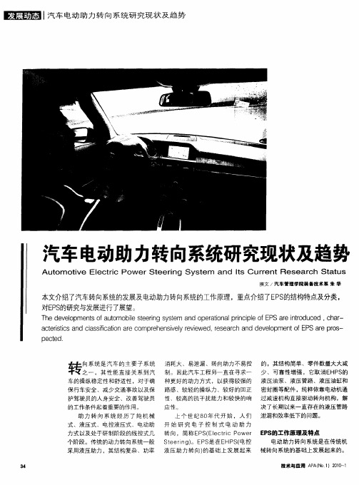
l 汽车电动助力转向系统研究现状及趋势
汽车电动助力转向系统研究现状及趋势
A u om ot e t i w erSt t i ve El c r Po c eer y t d I Uren i ng S s em an t C s r t Rese ch St t ar a us
感器) ,转 向助 力 机构 ( 电机 、 离合 的液压 助 力转 向系统 无法 做到 这一 器 、减 速 传动 机 构 ) 电子 控 制 装 点。 及 置 。 电动 机仅 在需 要助 力时工 作 ,
( ) 高 了 操 纵 稳 定 性 。 当驾 5提
驾驶 员在操 纵转 向盘 时 ,扭 矩转 角 驶 员转动转 向盘 一 角度 ,然后松 开 传 感器根 据输入 扭矩 和转 向角 的大 时 ,E S P 系统 能够 自动 调 整使车 轮 小产 生相应 的 电压 信 号 ,车 速传 感 回正 。同 时还可 利用软 件在 最大 限 器检 测到车 速信 号 ,控制单 元根 据 度 内调 整设 计参数 以获 得最 佳 的回 电压 和车速 的信 号 ,给 出指 令控 制 正 特 性。而 在传统 的液 压控 制系统 电动机 运转 ,从 而产 生所需 要 的转 中 ,要 改善 这种特 性必 须 改造底盘 向助力。其结构示意 图如 图1 示。 所 与传 统 的液 压助 力转 向相 比 , ES P 系统具有一 系列 的优 点 。 的机械 结构 ,实现起来 很 困难 。
技术 与 应 用 A A(o1 0O 1 P N )21一
At ov lt o eS en yt dtCrnRsa h tul u m te e r Pw rt rg s ma s uet eer a s同团田 o i E ci c e i S e n I r c S t
电动助力转向系统研发生产方案(一)
电动助力转向系统研发生产方案一、实施背景随着全球汽车工业的快速发展,消费者对汽车性能和安全性的需求日益增长。
作为汽车关键零部件之一,转向系统在提高驾驶体验和确保行车安全方面具有举足轻重的作用。
传统液压转向系统由于其能耗高、效率低等问题,已无法满足现代汽车业的发展需求。
为了应对这一挑战,我们提出了电动助力转向系统的研发生产方案。
二、工作原理电动助力转向系统(EPS)主要利用电机和减速机构为方向盘提供助力,从而提高转向的轻便性和准确性。
其核心部件包括电机、扭矩传感器、控制器和减速机构。
电机通过扭矩传感器感知驾驶员输入的扭矩,控制器根据采集的信号计算出合适的助力大小,然后驱动电机转动,通过减速机构将助力传递到方向盘。
三、实施计划步骤1.开展市场调研,分析电动助力转向系统的需求及竞争态势。
2.进行技术可行性研究,包括电机、扭矩传感器、控制器和减速机构的设计与选型。
3.搭建系统试验平台,进行性能测试与验证。
4.与汽车制造商合作,将电动助力转向系统集成到汽车中,进行实车测试。
5.根据测试结果进行优化改进,确保系统的性能和质量。
6.正式投产并推向市场。
四、适用范围本研发生产方案适用于各类乘用车、商用车以及特种车辆的转向系统升级或替换。
特别是对于那些追求高性能、高安全性和低能耗的汽车制造商和消费者,电动助力转向系统具有较大的市场潜力。
五、创新要点1.采用先进的电机技术和控制算法,提高系统的能效比。
2.设计简洁、紧凑的减速机构,降低系统成本并提高可靠性。
3.整合多种安全功能,如车道偏离预警、自动泊车等,提升驾驶安全性。
4.提供个性化设置选项,满足不同驾驶员的需求。
六、预期效果1.提高转向系统的助力效果,使驾驶更加轻松省力。
2.降低车辆能耗,实现节能减排。
3.提高车辆的安全性能,减少交通事故风险。
4.为汽车制造商提供新的盈利点,提高市场竞争力。
七、达到收益根据市场调查和分析,预计电动助力转向系统的市场需求将逐年增长。
基于PLC的电动助力转向系统研究
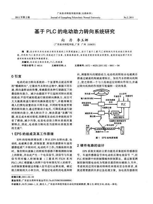
O 引言
电动 式 动 力 转 向系 统 的 一 个 显 著 特 点 就 是 所 谓 的 “ 确 转 向 ”它 能在 汽 车 转 向过 程 中 , 据 不 同 车 精 , 根
向 , 整 转 向 的辅 助 动 力 . 调 电动 机 的 转 矩 由 电 磁 离 合 器 通 过 减 速 机 构 减 速 增 矩 后 .加 在 汽 车 的转 向机 构
.
1 . 2
向
丹
李 玉娜 : 于 P C的 电动助力 转 向系统 研究 基 L
第 2期
于采集 电机反 馈 电流 ,该传感器 只有系统在助力控 制 时 才 会 激 活 . 参 数 与 电 机 目标 电流 的差 值 。 过 该 通 PD调节器 的控制 , 电机 迅速提供相应 的扭矩 , I 使 达 到 助 力 的 目的 . 电动 式 E S一 般 都 设 定 一 个 工 作 范 P 围 .故 障报警是用 于检测 E S系统各个参 数 的 , P 当 车速 、 电压 、 矩 中任 何 一 个 参 数 不 正 常 ( 过 限 定 扭 超 值 ) , 统 发 生 故 障 , 系 统 报 警 , 时 立 即 断 开 时 系 则 同 电动 助力控 制 系 统 ,使转 向系统 处 于 机械 转 向状 态 , 免 事 故 发 生 . 车 速 、 避 当 电压 、 矩 中任 何 一 个 扭 参 数 与其 限定 值 相等 时 , 故 障报 警 , 则 提示 驾 驶员 注 意. 另外 当电动机发 生故 障时 ,离合器会 自动分 离 , 时仍可利用 手动控制转 向. 这 系统 的硬件 结构 图
上 , 之得到一个 与工况相适应 的转 向作 用力, 使 并通 过 转 向机 构 的 作 用使 车 轮 偏 转 一定 的 角 度 .
.
- 1、下载文档前请自行甄别文档内容的完整性,平台不提供额外的编辑、内容补充、找答案等附加服务。
- 2、"仅部分预览"的文档,不可在线预览部分如存在完整性等问题,可反馈申请退款(可完整预览的文档不适用该条件!)。
- 3、如文档侵犯您的权益,请联系客服反馈,我们会尽快为您处理(人工客服工作时间:9:00-18:30)。
电动助力转向系统的开发研究
电动助力转向系统(Electric power steering,简称EPS)是世界汽车电子控制技术发展的研究热点和前沿技术之一。
国外汽车电动助力转向已部分取代传统液压动力转向(Hydraulic power steering,简称HPS)。
目前国内清华大学、合肥工业大学等高校正从事该方面的研究,并取得了阶段性的成果,争取进一步改进与完善,早日实现商品化。
EPS 通过对控制器软件的设计,十分方便地调节系统的助力特性,使汽车能在不同车速下获得不同的助力特性,以满足不同的驾驶情况的需求。
同时,EPS 用电动机直接提供助力,它能
节约燃料,提高主动安全性,有利于环保。
1、助力转向系统的类型及EPS的基本控制策略
1.1 助力转向系统的类型
(1)传统液压动力转向
液压动力转向的控制阀采用滑阀式,即控制阀中的阀以轴向移动来控制油路。
这种滑阀式控制结构简单,生产工艺性好,操纵方便,宜于布置,使用性能较好。
但是滑阀式控制阀灵敏度不够高,后来逐渐被转阀代替。
(2)电控液压动力转向
电控液压动力转向系统的种类很多,但其原理基本上都是通过在油泵或转向器上加装电子执行机构或辅助装置,根据车速信号来控制液压系统的流量或压力。
表1 电控液压动力转向系统的种类
(3)电动助力转向系统(EPS)的工作原理
图1 EPS的控制系统示意图
1—车轮2—拉杆3—齿条4—小齿轮5—离合器6—动力开关
7—输出轴8—扭杆9—转矩传感器10—输入轴11—方向盘
12—转矩信号13—电机14—电流控制15—控制单元16—车速信号
电动助力转向系统的基本组成包括:扭矩传感器、车速传感器、控制元件、电动机和减速机构等。
图1 所示为配用齿轮齿条式转向器的EPS。
信号控制器根据各传感器的输入信号确定助力扭矩的幅值和方向,并且直接控制电机。
电机的输出扭矩由减速齿轮放大,并通过万向节、转向器中的传送装置把输出扭矩送到齿条,使之向转向轮提供助推扭矩。
系统的信号源包括:扭矩传感器、转向角传感器和车速传感器,转向角传感器可根据齿条的位移量和位移的方向来测出转向角。
(4)EPS 的关键部件
1.2 EPS 的控制原理图
图2 汽车EPS控制原理图
EPS 主要部件包括传感器、电动机、减速机构和电子控制单元等。
在掌握EPS 的工作原理前提下,将EPS 系统用框图表示如下。
1.3 EPS 的基本控制策略
根据汽车转向行驶的不同情况要求,EPS 按不同的控制方式进行控制,通常来说,对应汽车转向行驶的不同情况有四种基本控制方式。
(1)普通控制
普通控制(助力控制)是EPS 的基本控制模式。
其控制过程主要是:根据车速传感器测得的车速信号和方向盘力矩传感器测得的方向盘力矩信号,调用助力特性控制表,并根据电动机的电磁转矩特性确定助力电流,以获得适当的助力转矩。
(2)回正控制策略
在方向盘“转向回正”时,对EPS 进行的控制为回正控制,目的在于改善系统的回正性能。
转向时,前轮回正力矩使转向轮向直线行驶的状态变化。
回正控制的控制过程为:首先判断方向盘是否处于“转向回正”状态,当助力电机旋转方向和转向输
入的旋转方向相反,进行“转向回正”控制,否则进行助力控制。
(3)阻尼控制策略
阻尼控制是EPS 为提高汽车高速直线行驶时的稳定性,减小路面冲击对方向盘的影响而采用的一种控制模式。
阻尼控制是在普通控制确定的目标电流之上补偿阻尼控制电流,其主要是通过引入电动机转速的方法来实现。
(4)补偿控制策略
补偿控制策略是根据转向作用力的变化率沿力矩变化的方向产生补偿力矩,来克服电机的惯量、阻尼和摩擦对电机输出力矩的影响。
补偿力矩的大小由电机的惯量、阻尼和摩擦力的大小及电机的转速、转向加速度和转动方向决定。
2、EPS仿真的初步研究及控制仿真验证
2.1 理想助力特性
配备电动助力装置的汽车转向系统,应尽可能不悖于驾驶员原有的驾驶习惯,这样驾驶员才能在转向时得心应手。
方向盘力矩与助力矩之间的理想关系应具备以下特点:
(1)在输入转向力矩很小的区域,希望助力部分的输出越小越好,助力部分基本不起作用,以保持较好的路感。
(2)在常用的快速转向行驶区间,为使转向轻便,降低驾驶员劳动强度,助力部分发挥作用,助力效果要明显。
(3)原地转向时的转向阻力矩很大,应尽可能产生较大的助力转向效果,此时,助力矩增幅也应较大。
(4)随着车速的升高,方向盘力矩减小时,不助力的区域应增大,且在高速行驶至一定车速时停止助力,以使驾驶员获得良好的路感,保证行车安全。
(5)各区段过渡要平滑,避免操作力出现跳跃感,且助力矩不能大于同工况下无助力时的转向驱动力矩。
将上述特点与原则量化,可得理想的助力特性曲线。
如图3 所示,由于电动机输出转矩与电流
间存在线性关系,因此该图反映出助力矩随行驶工况的变化规律,可以把它作为研究电动机控制规律的参照。
图3 理想助力特性
2.2 控制系统的选择
对助力电动机输出转矩的控制是EPS 研究的重点。
由于电动机的输出转矩是由其工作电流决定的,因此助力控制可归结为对电动机电流的控制(如图4),其控制输入为车速信号和方向盘扭矩信号。
图4 控制系统框图
控制系统主要采用PID 控制系统。
PID 控制是最早发展起来的控制策略之一,由于算法简单、和可靠性高,被广泛应用于过程控制和运动控制,尤其适用于可建立精确数学模型的确定性控制系统。
图5 典型的PID控制结构
图5 所示为典型的PID 控制系统结构。
PID 控制器是由比例、积分和微分三个环节叠加构成的,各环节分别对误差信号e(t)进行运算,其结果的加权和将构成系统的控制信号u(t)一并送给对象模型。
PID 控制器的数学描述为:
(公式1)
式中:kp—比例环节调整参数;
ki—积分环节调整参数;
kd—微分环节调整参数。
PID 控制器各环节所起的作用如下:
(1)比例环节抑止闭环系统的瞬态偏差信号e(r),通过增加kp值还可加快系统响应速度,提高闭环响应的幅值。
但kp值不能无限制增加,对于不同的闭环控制系统kp的取值范围不同,超出该限制范围,系统将不稳定;
(2)积分环节主要用于消除系统的静差,提高系统的无差度。
积分作用的强弱取决于积分的时间常数K;K 越大积分作用越弱,反之则越强。
而过强的积分作用使系统的超调量增加,系统的稳定性变坏;
(3)微分环节能反映偏差信号的变化趋势(变化速率),并能在偏差信号值变大之前,在系统中引入一个有效的早期修正信号,从而加快系统的动作速度,减少调节时间。
其不足之处是放大了噪音信号。