PT100多路温控器说明书
Pt100探头原理解释及接线说明(图文)
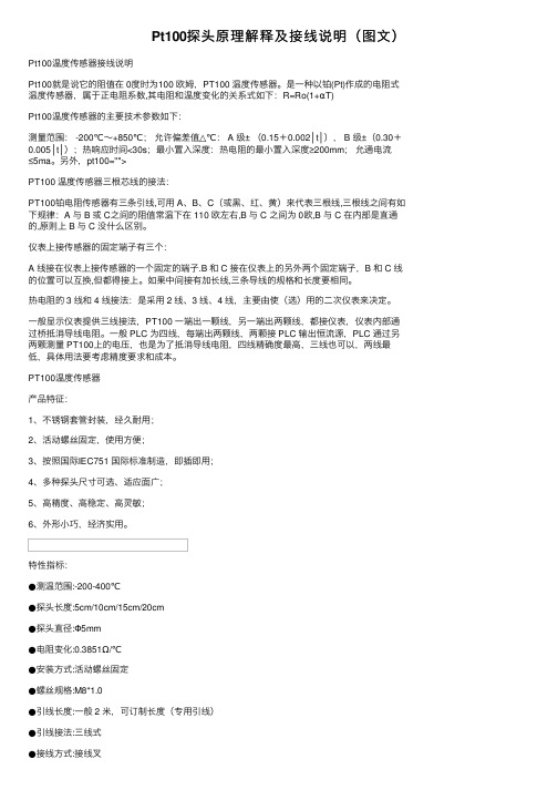
Pt100探头原理解释及接线说明(图⽂)Pt100温度传感器接线说明Pt100就是说它的阻值在 0度时为100 欧姆,PT100 温度传感器。
是⼀种以铂(Pt)作成的电阻式温度传感器,属于正电阻系数,其电阻和温度变化的关系式如下:R=Ro(1+αT)Pt100温度传感器的主要技术参数如下:测量范围: -200℃~+850℃;允许偏差值△℃: A 级± (0.15+0.002│t│), B 级±(0.30+0.005│t│);热响应时间<30s;最⼩置⼊深度:热电阻的最⼩置⼊深度≥200mm;允通电流≤5ma。
另外,pt100="">PT100 温度传感器三根芯线的接法:PT100铂电阻传感器有三条引线,可⽤ A、B、C(或⿊、红、黄)来代表三根线,三根线之间有如下规律:A 与 B 或 C之间的阻值常温下在 110 欧左右,B 与 C 之间为 0欧,B 与 C 在内部是直通的,原则上 B 与 C 没什么区别。
仪表上接传感器的固定端⼦有三个:A 线接在仪表上接传感器的⼀个固定的端⼦.B 和C 接在仪表上的另外两个固定端⼦,B 和 C 线的位置可以互换,但都得接上。
如果中间接有加长线,三条导线的规格和长度要相同。
热电阻的 3 线和 4 线接法:是采⽤ 2 线、3 线、4 线,主要由使(选)⽤的⼆次仪表来决定。
⼀般显⽰仪表提供三线接法,PT100 ⼀端出⼀颗线,另⼀端出两颗线,都接仪表,仪表内部通过桥抵消导线电阻。
⼀般 PLC 为四线,每端出两颗线,两颗接 PLC 输出恒流源,PLC 通过另两颗测量 PT100上的电压,也是为了抵消导线电阻,四线精确度最⾼,三线也可以,两线最低,具体⽤法要考虑精度要求和成本。
PT100温度传感器产品特征:1、不锈钢套管封装,经久耐⽤;2、活动螺丝固定,使⽤⽅便;3、按照国际IEC751 国际标准制造,即插即⽤;4、多种探头尺⼨可选、适应⾯⼴;5、⾼精度、⾼稳定、⾼灵敏;6、外形⼩巧,经济实⽤。
LABCAL-PRO Pt100 和热敏电阻传感器精密温度计 记录器说明书

LABCAL-PROThe Labcal PRO is a third generation instrument developed over a 25 year period from the very successful Labcal Plus thermometer. Like its predecessors, the Labcal PRO provides laboratory standard temperature measurement and many user features but provides higher accuracy, higher resolution and greater versatility to extend the scope of applications.The Labcal PRO is fully characterised for Pt100 sensors and all major thermocouples J,K,N,T,E,R,S and B. Exceptionally stable automatic cold junction compensation with a rejection of 100:1 is incorporated for thermocouple ranges. Alternatively, external or manual referencing can be selected as required.Displayed values and user information are indicated on a bright clear OLED screen with diffused backlighting. Data can be displayed in °C,°F,K,Ωor mV as required; nine front panel push keys, the only user controls, are used in conjunction with the display screen. It is this arrangement which makes for very simple and “friendly” operation.Resolution is a user selectable 0.001 or 0.01°C for Pt100 sensors and 0.1°C for thermocouples. All computations are performed digitally without drift. Overall stability is optimised by utilising only the highest quality components including high precision, expensive metal film resistor networks.There are four input ports, two for thermocouples and two for 3 or 4 wire Pt100 sensors; the instrument automatically recognises 3 or 4 wire configurations.The Labcal PRO can accept two Pt100 sensors and/or two thermocouples of similar or different types (J,K,N,T,E,R,S and B). The measured temperature can be displayed directly from one of the inputs or differentially between similar or different inputs. Differential temperature and the two individual channel temperatures are displayed simultaneously.Individual calibrated sensors can have their appropriate calibration values programmed into the Labcal PRO using either the keypad or the PC software supplied. The PC software also allows corrections in the form of constants for individual Pt100 sensors to be programmed in. The non-volatile memory ensures that the values are retained (until such time as they are changed) even after switch-off. Where the calibration certificate relating to a particular probe states specific Ωor mV values at stated temperatures, up to ten such values are entered into the Labcal PRO with their relevant temperature points using the front panel keypad or the software. The instrument then digitally self-calibrates to the associated probe over the range embraced in the calibrated values used; the temperature readout is “corrected” accordingly. Additional manual procedures are not required to compute precise temperature readings since these are displayed directly; miscalculation errors are thus eliminated. Very high system accuracies, better than 25 milliKelvins can be achieved using probe matching.Corrections which are “programmed in” can be displayed for confirmation. However, initial input, adjustment, enabling and disabling of corrections are protected by a special key sequence to preventaccidental or unauthorised changes. Values can be changed by an authorised user at any time.For Pt100 inputs, SMART probes can be used which incorporate dedicated ‘correction values‘ within the connector of each probe.When a SMART probe is connected to input A or B or both inputs,the corrections are automatically applied without the need for user intervention.A common application for the Labcal PRO is the comparison calibration of “working” sensors against a calibrated reference standard or semi-standard sensor. For example, the sensor under test in channelB is compared against the reference sensor (with programmed corrections) in channel A. When applied, the null function corrects the differential temperature readout between two sensors to zero. For example, the apparent temperature difference between two sensors known to be at the same actual temperature can be corrected to zero prior to, for example, heat exchanger experiments.All four inputs can be scanned and values logged according to parameters set up by the user in the PC software;the instrument incorporates a real-time clock and on-board memory.The adjustable contrast OLED display screen provides data readout, user prompts and mode annunciation. This very important feature ensures a high degree of user friendliness and confidence. User prompts indicate which buttons to press in the appropriate sequence when selecting parameters and functions and when setting calibration values. Mode annunciation indicates which mode of operation is currently selected.A flash drive USB port is provided to allow data to be stored and/or exported. Firmware update are also facilitated via this port.PC software running in WINDOWS is provided as standard; it allows programming of custom calibration, remote control & measure and logging functions.SPECIFICATIONSAll values are valid for a nominal 240V 50Hz instrument supply and 20ºC ambient temperature(±2ºC)GeneralInputs/Ranges/SensorsType Pt100 to IEC 751 (ITS 90 refers).-200ºC to +850ºCRo = 100Ω3 or4 wire connection with automatic recognition(with manual override)Thermocouples to IEC 584No isolation exists between inputs.Type Type S -50 to 1768ºCType R -42 to 1766ºC Noble MetalType B +254 to 1818ºCType J -200 to 1200ºCType K -195 to 1370ºCType E -190 to 995ºC Base MetalType N -160 to 1300ºCType T -193 to 399ºCOverall Pt100Accuracy±0.01ºC ±0.0005% of spanThermocouplesi) Base Metal ii) Noble Metal±0.2ºC from -50ºC to 700ºC±0.3ºC from 850ºC tofull scale±0.4ºC from -200ºC to -50ºC±0.4ºC below 850ºC±0.4ºC from 700ºC to ±0.7ºC below 0ºCfull scaleNote:Type B not characterized below +200ºC Linearisation ConformityPt100Better than ±0.01ºCThermocouples±0.05ºC base metal (-200ºC to span)±0.1ºC noble metal above 200ºCNote: Performance of ADC (0.5µV resolution ) is superior to published thermocouple table best resolution of 1µV.Stability (vs ambient temperature)Pt100Better than 0.0025ºC per 1ºC ambient changeThermocouplesZero: negligible drift excluding CJC effectScale: < ±0.1ºC in 15ºCWarm-up Negligible under normal ambient conditions. Allow 5-10 minutes for full stability unless stored at low temperature,then 30 minutes minimum.Cold Junction CompensationAutomatic on all thermocouple ranges. Better than ±1ºCmax shift for ±10ºC ambient variation (100:1) or Externalvia Pt100 on channel A or B or Manual input of CJtemperature value.Pt100 Sensor Current0.5mAResolution of data displayPt1000.01/0.001 user select for ºC, K and ΩVariable filterSampling rate selectable between 4 and 64(measurements averaged per reading).Thermocouples0.1ºC all rangesLABFACILITY LIMITED SOUTHERN UK & EXPORT DIVISION :Units 5,6 & 7, Block K, Southern Cross Industrial Estate, Shripney Road, Bognor Regis,West Sussex PO22 9SE Export Sales:tel: +44(0)1243 871287fax: +44(0)1243 871281email: exportsales@Southern UK Sales:tel: +44(0)1243 871280fax: +44(0)1243 871281email: southernsales@NORTHERN UK DIVISION :Eden Place, Unit 3b Outgang Lane, Dinnington, Sheffield S25 3QTNorthern UK Sales:tel: +44(0)1909 569446fax: +44(0)1909 550632email: northernsales@Data Ref: 050111DS/ASpecifications may be subject to change.Measurement UnitsºC, ºF, K, Ωor mV as applicable to sensor Measurement ModesA, B or A-B. Any combination of sensor types.Custom CalibrationUp to 10 calibration values can be allocated to Pt100input A & B and to thermocouples input A & B. Values are retained in non-volatile memory until replaced by user. Alternatively, for Pt100 inputs ITS 90 or IPTS 68coefficients can be used for custom calibration.Smart Sensor ConnectionPt100 inputs only. Correction values stored in connector.Null FunctionCorrects differential temperature readout between two sensors to zero.Sensor LeadPt100Resistance 5Ωeach lead maximumThermocouples 300Ωloop totalLogging 8000 readingsSupplyInternal Lithium Ion rechargeable batteries. Mains 90-260V 50/60Hz universal adaptor included. Battery charge life up to 12 hours with full charge.Series Mode Rejection60dB @ 50Hz (50mV RMS applied)Common Mode Rejection30V RMS applied between input and earth produces no measurable effect.Display128 x 64 pixel OLED with diffused backlighting. Wide viewing angle, high contrast (adjustable).Front Panel Controls9 membrane push-keys to control all instrument functions Mechanical/CaseMetal bench top case / adjustable tilt DimensionsOverall190mm(W) x 70mm(H) x 250mm(D)Weight3.0kg approx.Input Connections2 x Pt100 via D type connectors2 x Thermocouple via standard sockets.USB Serial CommunicationsIsolated, 9600 Baud, 8 data, no parity, 1 stop bit. Remote control and measure.PC Software (standard)Supplied as standard on CD ROM. Remote control and measure: Log readings to file/Download to PC/Programming corrections Analogue Output (standard)User programmable, 0 to 5VApplication Note:Inputs are not isolated in the Labcal PRO which is primarily designed for laboratory applications and site calibration of industrial temperature sensors. Probes connected to the instrument must therefore be isolated from high voltage pick-up. Particular care must be taken when high temperature thermocouples are used with ceramic (refractory oxide) sheaths; these can become electrically conductive at elevated temperatures and mains pick-up can occur from electrical heaters.The instrument should be disconnected from the mains adaptor and operated from its internal batteries in such situations.ACCESSORIES AND ORDER CODESLabcal PRO is supplied complete with switch mode power supply (90-260V, 50/60Hz), two Pt100 "D" connectors, operating manual and PC software.Precision Pt100 ProbesStainless steel probes, 6mm diameter with 2m screened PTFE lead and connector LP-L250: 250mm long, maximum 250ºC LP-H450:350mm long, maximum 450ºCUKAS CalibrationLP - UKAS: UKAS calibration for instrument alone.LP - SYS.CAL: UKAS calibration of instrument and sensortogether at five points.LP - COR.CAL: UKAS calibration of instrument and sensortogether at five points, after initial calibration of sensor only and programming of corrections.AccessoriesLP - TBLK3: Terminal Block for connection of 3 wire Pt100s LP - TBLK4:Terminal Block for connection of 4 wire Pt100sLABCAL-PRO。
pt100使用简介
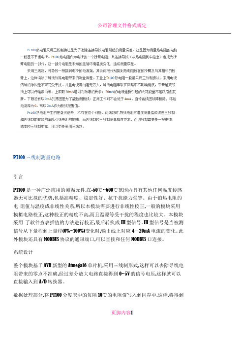
PT100三线制测量电路引言PT100 是一种广泛应用的测温元件,在-50℃~600℃范围内具有其他任何温度传感器无可比拟的优势,包括高精度、稳定性好、抗干扰能力强等。
由于铂热电阻的电阻值与温度成非线性关系,所以本模块需要进行非线性校正,一般的模块采用模拟电路校正,这种校正的精度不高,而且温漂等受干扰的程度也比较大。
本模块采用了软件查表插值的方法进行校正,最后转换成III型信号。
III型信号是当被测信号从下量程到上量程(0%~100%)变化时,输出线上对应4-20mA 电流的变化。
此外模块还具有MODBUS协议的通讯端口,可以直接和任何MODBUS口连接。
系统设计整个模块基于AVR新型的Atmega16单片机,采用三线制形式,这样可以去除导线电阻带来的零点不准确,经过差分放大电路直接得到0~5V的信号电压,这样就可以直接输入到A/D转换器。
数据处理部分,将PT100分度表中的每隔10℃的电阻值写入到闪存中,这样,将得到页脚内容1电压值回算到电阻值,这样进行查表,当电阻位于某一段之间时,再进行线性处理,这样系统的线性化程度比较高可以达到0.2%。
D/A转换系统采用373芯片作为锁存器,采用权电阻网络进行D/A转换,这样可以节省成本,而且精度也可以得到保证。
最后再经过一个电压电流转换部分,把信号以III型信号传送出去,完成模块的功能。
图1 采样电路采样电路采样电路如图1所示,PT100以三线制接到J0,这样连接PT100的两侧的导线长度相等,而且分别加在两侧的桥臂上,这样导线电阻得以消除,当 PT100输出100Ω时可以调节R1的阻值,以调整温度下限,当温度范围是0~300℃时,电桥电压经过放大后,Anolog0的电压正好是0~5V, 这样可以完整使用单片机的A/D转换器的转换精度。
页脚内容2图2 主机电路主机电路如图2。
CPU采用Atmega16 ,它自带8路10位A/D转换器,转换速度快,精度高,而且不需要外扩任何器件。
普量电子PT100 热电偶温度变送器使用说明书

PT100/热电偶温度变送器产品使用说明佛山市普量电子有限公司2020-V1.0●欢迎选购佛山市普量电子有限公司产品。
●佛山市普量电子有限公司保留所有权利。
●产品订购和使用前请详细阅读《PT100/热电偶温度变送器使用说明书》。
●产品使用后,请保留《使用说明》,以便产品维护及售后服务。
一、产品外观及组成1、进口PT100铂电阻/J、K、E型热电偶温度芯体;2、高精度、稳定、数字标定调节、放大集成电路,具有零点、满量程补偿、温度补偿;3、输出信号类型广泛,4-20mA/0-20mA/0-5V/10V/RS485-RTU及低功耗RS485;4、产品响应快速,反应灵敏,精度高;5、结构多样化:螺纹安装式、铠装式、贴片式、插入式、法兰式等;6、电气连接IP65/68,二线/三芯/四芯屏蔽温度补偿线;7、304/316/制定材料外壳,探杆长度/直径/螺纹规格/法兰尺寸可制定;8、温度范围:-198℃~-40℃~0~100℃~500℃~1000℃;二、使用时注意事项安装使用请,核对产品标牌及合格证相关参数与使用工况是否相符合;热电阻/热电偶安装时,其插入深度不小于热电阻保护管外径的8倍~10倍;尽可能使热电阻/热电偶受热部分增长;热电阻/热电偶尽可能垂直安装,以防在高温下弯曲变形。
热电阻/热电偶使用中为了减小误差,应尽量使保护套管表面和被测介质温度接近;产品安装时,受力部位为“过程连接六方扳手位”,扳手规格与六方相对应;严禁被测系统的介质温度、压力量程、激励电压超过变送器的额定使用范围;注意保护传感器/变送器电缆线或补偿导线;尽量避免直接接近引起干扰的用户装置或电器;三、产品质量保证免责范围维修服务1、品质保证服务(1)产品质量实行三包:质保期以交货之日起计算,为期13个月。
在质保期内,如因产品本身质量问题,我公司提供免费维修、更换和退货服务。
1)、产品一般零部件、元器件失效,更换后即能恢复使用要求的,免费按期修复;2)、产品主要零部件、元器件失效,不能按期修复的,更换同规格的合格产品;3)、产品因设计、制造等原因造成主要功能不符合企业标准和合同规定的要求,客户要求退货时,收回故障产品,退回客户货款。
Testo 112 NTC- Pt100 测量仪使用说明书
Instruction manual entesto 112NTC-/Pt100 measuring instrumentContentsGeneral notes ......................................................21.Safety advice........................................................32.Intended purpose ................................................43.Product description. (5)3.1Display and control elements ..........................................53.2Interfaces........................................................................63.3Voltage supply . (6)4.Commissioning ....................................................75.Operation (8)5.1Connecting a probe ........................................................85.2Switching the instrument on / off ....................................85.3Switching the display light on / off ..................................95.4Performing settings .. (9)6.Measuring..........................................................127.Care and maintenance ......................................148.Questions and answers......................................159.Technical data....................................................1610.Accessories/spare parts (17)1.888.475.5235*********************www.Testo-Direct .comGeneral notes2General notesThis chapter provides important advice on using this documentation.The documentation contains information that must beapplied if the product is to be used safely and efficiently.Please read this documentation through carefully andfamiliarise yourself with the operation of the product beforeputting it to use. Keep this document to hand so that youcan refer to it when necessary.Identificationachieved via the steps described.Where steps are numbered,you must always follow the order given!Condition A condition that must be met if an action is to be carried out as described.i ,1,2,...Step Carry out steps.Where steps are numbered,you must always follow the order given!TextDisplay text Text appears on the instrument display.Control buttonPress the button.-ResultDenotes the result of a previous step.ºCross-reference Refers to more extensive or detailedinformation.Button 1.888.475.5235*********************www.Testo-Direct .com1. Safety advice31.Safety adviceThis chapter gives general rules which must be followedand observed if the product is to be handled safely.Avoid personal injury/damage to equipmenti Do not use the measuring instrument and probes tomeasure on or near live parts.i Never store the measuring instrument/probes togetherwith solvents and do not use any desiccants.Product safety/preserving warranty claimsi Operate the measuring instrument only within theparameters specified in the Technical data.i Always use the measuring instrument properly and for itsintended purpose. Do not use force.i Do not expose handles and feed lines to temperatures inexcess of 70 °C unless they are expressly permitted forhigher temperatures.Temperatures given on probes/sensors relate only tothe measuring range of the sensors.i Open the instrument only when this is expresslydescribed in the documentation for maintenance andrepair purposes.Carry out only the maintenance and repair work that isdescribed in the documentation. Follow the prescribedsteps when doing so. For safety reasons, use onlyoriginal spare parts from Testo.Ensure correct disposali Take faulty rechargeable batteries/spent batteries to thecollection points provided for them.i Send the product back to Testo at the end of its usefullife. We will ensure that it is disposed of in an*********************environmentally friendly manner. 1.888.475.52352. Intended purpose42.Intended purposeThis chapter gives the areas of application for which theproduct is intended.Use the product only for those applications for which it wasdesigned. Ask Testo if you are in any doubt.testo 112 is a compact, accurate measuring instrument formeasuring temperatures by means of plug-in temperatureprobes. Thanks to the possibility of connecting not onlyNTC probes, but also Pt100 probes, the testo 112 coversa wide measurement range and at the same time providesa high level of measurement accuracy.The following components of the product are designed for continuouscontact with foodstuffs in accordance with the regulation(EC) 1935/2004:The measurement probe up to 1 cm before the probe handle or theplastic housing. If provided, the information about penetration depthsin the instruction manual or the mark(s) on the measurement probesshould be noted.The product was designed for the followingtasks/applications:·Food sector·Laboratories·Applications requiring official calibration (only relevant forGermany):The testo 112 is approved for official calibration by thePhysikalisch-Technisches Institut PTB (nationalmetrology institute in Germany).Approval mark:The product should not be used in the following areas:·Areas at risk of explosion·Diagnostic measurements for medical purposes*********************1.888.475.52353. Produktbeschreibung 53.Product descriptionThis chapter provides an overview of the components of the product and their functions.3.1Display and control elementsOverviewInfrared interface, probe socket Display Control buttons Battery compartment (rear)Button functionsButton Functions Switch instrument on; switch instrument off (press and hold)In configuration mode: 1.888.475.5235*********************www.Testo-Direct .com3. Production description6Important displayscharged3.2InterfacesInfrared interfaceMeasurement data can be sent to a Testo printer via theinfrared interface on the head of the instrument.Probe socketA plug-in measuring probe can be connected via the probesocket on the head of the instrument.3.3Voltage supplyVoltage is supplied by means of a 9V monobloc battery(included in delivery) or rechargeable battery. It is notpossible to run the instrument from the mains supply orcharge a rechargeable battery in the instrument.*********************1.888.475.52354. Commissioning7missioningThis chapter describes the steps required to commissionthe product.²Removing t t he p p rotective f f ilm o o n t t he d d isplay:i Pull the protective film off carefully.²Inserting a a b b attery/rechargeable b b attery:1To open the battery compartment on the rear of theinstrument, push the lid of the battery compartment inthe direction of the arrow and remove it.2Insert a battery/rechargeable battery (9V monobloc).Observe the polarity!3To close the battery compartment, replace the lid ofthe battery compartment in position and push itagainst the direction of the arrow.*********************1.888.475.52355. Operation85.OperationThis chapter describes the steps that have to be executed frequently when using the product.5.1Connecting a probePlug-in probesPlug-in probes must be connected before the measuringinstrument is switched on so that they are recognised bythe instrument.i Insert the connector of the probe into the probesocket.5.2Switching the instrument on /off²Switching tt he i i nstrument o o n: i Press .- A segment test is carried out: All LCD-segments inthe display briefly light up.- A function test of the instrument and the probe is carried out. The instrument tests the entire measurement channel regarding the adherence to allowed margins of error.The type of probe attached is displayed for approx.2s (NTC or Pt 100).An error is detected:-rEF Error is displayed for approx. 2s, then ----- is displayed. Please contact your dealer or Testo customer service.The function test was successful:-Measurement view is opened: The current reading is displayed.1.888.475.5235*********************www.Testo-Direct .com5. Operation9²Switching t t he i i nstrument o o ff:i Press and hold (for approx. 2s) until the displaygoes out.5.3Switching the displaylight on/off²Switching t t he d d isplay l l ight o o n/off:The instrument is switched on.i Press .5.4Performing settings1To o o pen c c onfiguration m m ode:The instrument is switched on and is in measurementview. Hold, Max or Min are not activated.i(for approx. 2s) until the displaychanges.-The instrument is now in configuration mode.(for approx. 2s) until thechanges that have already been made in configurationmode will be saved.2To s s et t t he a a larm f f unction:Configuration mode is opened, ALARM is lit.1/and confirm·oFF: Switches the alarm function off.·on: Switches the alarm function on.oFF was selected:ºContinue with objective T O SET THE MAX./MIN. PRINTFUNCTION.1.888.475.5235 *********************5. Operation10on was selected:2to set the value for the upper alarm3to set the value for the lower alarm3To s s et t t he m m ax./min. p p rint f f unction:MaxMin is flashing.i/and confirm·on: Maximum and minimum values are printed outas well when current or recorded readings areprinted.·oFF: Maximum and minimum values are not printedout as well when current or recorded readings areprinted.4To s s et A A uto O O ff:Configuration mode is opened, AutoOff is flashing.i/and confirm·on: The measuring instrument switches offautomatically if no button is pressed for 10min (Holdor Auto Hold is lit).·oFF: The measuring instrument does not switchitself off automatically.5To s s et t t he d d ate/time:Configuration mode is opened, YEAR is lit.1to set the current YEAR and confirm2to set the other values for the month() and time (TIME) and confirm each*********************1.888.475.52355. Operation116To s s et t t he u u nit o o f m m easurement:Configuration mode is opened, UNIT is lit.i/7To r r eset:Configuration mode is opened, RESET is lit.i and confirm·no: Instrument is not reset.·Yes: Instrument is reset. The instrument is reset tothe factory settings.The setting of date/time is not reset.-The instrument returns to measurement view.e1.888.475.5235 *********************6. Measuring126.MeasuringThis chapter describes the steps that are required toperform measurements with the product.²Taking a a m m easurement:The instrument is switched on and is in measurementview.i Put the probe in position and read off the readings.With the alarm function on and if the alarm thresholdis exceeded or undershot:-flashes and a signal tone is given.-The alarm goes out if the reading goes below theupper or above the lower threshold again.²Holding t t he r r eading, d d isplaying t t he m m aximum/minimumvalue:The current reading can be recorded. The maximum andminimum values (since the instrument was last switchedon) can be displayed.i several times until the desired value is-The following are displayed in turn:·Hold: the recorded reading·Max: Maximum value·Min: Minimum value·The current reading-In addition to the maximum or minimum readings,the 2nd reading line shows the current reading.*********************1.888.475.52356. Measuring 13²Resetting tt he m m aximum/minimum v v alues: The maximum/minimum values of all channels can be reset to the current reading.1several times until Max or Min lights up.2-All maximum or minimum values are reset to the current reading.²Printing rr eadings: The readings shown on the display (current reading,recorded reading or max./min. reading) can be printed out.A Testo printer is required (accessory part).With the Max./Min. print function switched on, the maximum and minimum values are printed out as well as the current reading or recorded reading.ºSee the chapter P ERFORMING SETTINGS .1Configure the instrument so that the value to beprinted is shown on the display.2-·The measurement value ·The date and timeOnly relevant for applications requiring official calibration in Germany:·A protocol line with the text:Der ausgedruckte Messwert stimmt mit der Anzeige des geeichten Messgeräts überein . (The printed measurement value corresponds to the display of the officially calibrated measuring instrument.)·A signature line1.888.475.5235*********************www.Testo-Direct .com7. Care and maintenance147.Care and maintenanceThis chapter describes the steps that help to maintain thefunctionality of the product and extend its service life.±Cleaning t t he h h ousing:i Clean the housing with a moist cloth (soap suds) if itis dirty. Do not use aggressive cleaning agents orsolvents!±Changing t t he b b attery/rechargeable b b attery:The instrument is switched off.1To open the battery compartment on the rear of theinstrument, push the lid of the battery compartment inthe direction of the arrow and remove it.2Remove the spent battery/rechargeable battery andinsert a new battery/rechargeable battery(9V monobloc). Observe the polarity!3To close the battery compartment, replace the lid ofthe battery compartment in position and push itagainst the direction of the arrow.*********************1.888.475.52358. Questions and answers15 8.Questions and answersThis chapter gives answers to frequently asked questions.Question Possible causes Possible solutionis lit (bottom right·Instrument battery is ·Replace instrumentin display).almost spent.battery.Instrument switches ·Auto Off function ·Switch function off.itself off automatically.is switched on.·Residual capacity ·Replace battery.of battery is too low.Display:-----·Probe is not plugged in.·Switch instrument off,connect probe andswitch instrumentback on again.·Probe break.·Please contact yourdealer or TestoCustomer Service.Display reacts slowly·Ambient temperature ·Raise ambientis very low.temperature.Display: uuuuu·Permitted measuring ·Keep to permittedrange was undershot.measuring range.Display: ooooo·Permitted measuring ·Keep to permittedrange was exceeded.measuring range.Display: rEF Error·Reference measurement·Please contact yourout of tolerance of dealer or Testo±0.1°C Customer Service.If we are unable to answer your question, please contactyour dealer or Testo Customer Service. Contact details canbe found on the guarantee card or on the Internet under.*********************1.888.475.52359. Technical data169.T echnical dataInstrumentCharacteristic ValueParameters Temperature (°C/°F)Measuring range Pt100 probe: -50...+300°C / -58...+572°FNTC probe: -50...+120°C / -58...+248°FResolution0.1°C / 0.1°FAccuracyºSee S YSTEM ACCURACYProbe1x mini DIN socket for Pt100 or NTC temperature probeMeasuring rate2/sOperating temperature range-20...+50°C / -4...+122°FStorage temperature-30...+70°C / -22...+158°FVoltage supply1x 9V monobloc battery/rech. batteryBattery life approx. 70hProtection class with TopSafe (accessory part) and probe connected:IP65EC Directive89/336/EECWarranty 2 yearsSystem accuracyMeasuring range Instrument Probe SystemMeasuring instrument + NTC temperature probe-50.0°C...-25.1°C±1%of reading±0.7%of reading±1.8%of reading-25.0...+40.0°C±0.2°C±0.2°C±0.5°C+40.1...+80.00°C±0.3°C±0.4°C±0.8°C+80.1...+120.0°C±0.5°C±0.6°C±1.2°CMeasuring instrument + Pt100 temperature probe-50.0...-25.1°C±0.2°C±0.3°C±0,6°C-25.0...+40.0°C±0.2°C±0.2°C±0.5°C+40.1...+140.0°C±0.2°C±0.4°C±0.7°C+140.1...+200.0°C±0.2°C±0.6°C±0.9°C+200.1...+300.0°C±0.3°C±0.8°C±1.2°C*********************1.888.475.523510. Accessories/spare parts17 10.Accessories/sparepartsName Part no.NTC probesWater-proof NTC immersion/penetration probe0613 1212Water-proof NTC surface probe for smooth surfaces0613 1912Efficient, robust air probe, NTC0613 1712Pt100 probesRobust, water-proof Pt100 immersion/penetration probe0609 1273Efficient, robust air probe, Pt1000609 1773MiscellaneousTopSafe testo 112, protects from impact and dirt particles0516 0221For a complete list of all accessories and spare parts,please refer to the product catalogues and brochures orlook up our website: *********************1.888.475.5235Notes18*********************1.888.475.5235Notes19*********************1.888.475.52350977.1121/02/T/dr/14.03.2006w w w .t e s t o .c o mtesto AGPostfach 1140, 79849 Lenzkirch Testo-Straße 1, 79853 Lenzkirch Telefon: (07653) 681-0Fax: (07653) 681-100E-Mail:*************Internet: 1.888.475.5235*********************www.Testo-Direct .com。
pt100铂电阻说明书

pt100铂电阻说明书【PT100铂电阻说明书】一、产品概述PT100铂电阻是一种温度传感器,广泛应用于各种工业领域中对温度进行测量的需求。
本说明书将为您介绍PT100铂电阻的基本原理、技术参数、使用方法以及注意事项。
二、基本原理PT100铂电阻的温度测量原理是通过铂电阻的电阻值随温度变化而产生的线性关系,实现温度的测量。
随着温度的升高,铂电阻的电阻值也会相应增加,反之亦然。
PT100铂电阻的可靠性和准确性使其成为工业温度测量的首选传感器之一。
三、技术参数1. 电阻值:PT100铂电阻的电阻值为100欧姆,在温度为0℃时,其电阻值为100欧姆。
2. 温度范围:PT100铂电阻的测量温度范围通常为-200℃至600℃,但实际可根据具体需求定制。
3. 线性关系:PT100铂电阻的电阻值与温度呈线性关系。
在标准条件下,每摄氏度的温度变化约对应0.385欧姆的电阻变化。
四、使用方法1. 连接方式:将PT100铂电阻的两端与测量仪器进行连接,确保接触良好并固定牢固。
2. 温度校准:在使用前,建议进行温度校准以确保测量结果的准确性。
使用专用温度校准设备,按照说明进行校准操作。
3. 安装位置:根据具体需求选择合适的安装位置,避免暴露在过高温度或腐蚀性介质中,以免影响传感器的正常使用寿命。
4. 保养维护:定期检查PT100铂电阻的连接状态和电阻值变化,如有异常及时处理或更换。
五、注意事项1. 使用环境:避免将PT100铂电阻使用于超出其额定温度范围的环境中,以免损坏传感器或影响测量准确性。
2. 防护措施:根据实际需求,采取相应的防护措施,如加装防护套管、防水罩等,以延长PT100铂电阻的使用寿命。
3. 注意连接性:在连接过程中,应确保PT100铂电阻与测量仪器的连接稳定可靠,避免接触不良或短路等情况。
4. 避免冲击:PT100铂电阻属于精密仪器,在使用过程中需避免剧烈振动或外部冲击,以免影响其性能。
5. 专业维修:如遇到无法解决的故障或损坏情况,请联系专业技术人员进行维修或更换。
多路温度控制器说明书
多路温度控制器说明书一、功能概述采用高性能单片监控芯片为核心,确保了产品测控的精确性、稳定性。
是一款高精密度、高集成性的控制器。
该产品可以同时配接多路传感器,可以同时对一个环境进行多重控制,或独立监测、控制多个环境的温度。
产品分为4路温度控制;8路温度控制;12路温度控制。
可以分别数字显示12路(最多12路)环境测量的温度值。
产品带有独立的自整定模式和独立的PID参数,且具有计算机通讯功能。
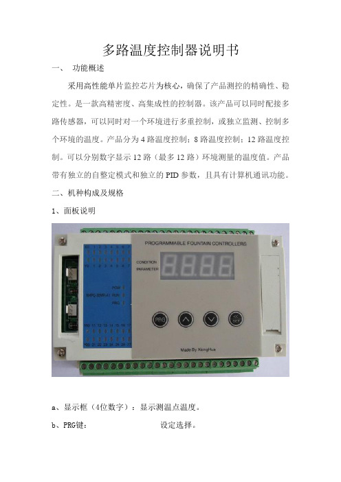
二、机种构成及规格1、面板说明a、显示框(4位数字):显示测温点温度。
b、PRG键:设定选择。
连续按3秒:进入或退出设定模式。
c: SET键:设置/移位键。
连续按1.5秒:进入或退出设置状态点动按键:移动设定数据位置。
d、点动∧和∨键(增/减)键。
按一次,设定时间数据增/减“1”若按下不放,则连续增/减。
2、技术参数表二、控制器接线方式三、控制器外形及按装尺寸可以采用平底导轨或螺栓固定方式安装。
四、程序设定表程序序号功能设定数值说明Cd00 PID自整定设定101~112 按顺序1-12路分别自整定Cd01-12 1-12路温度设定0-999.9度按顺序分别设定温度Cd13 温度超偏差 5.0度超过5度报警Cd14 Pid工作范围30.0 范围外输出为100%Cd15 温度超偏差停机 2.0度Cd16 滤波系数80 0-99%Cd18 Pid工作周期3秒0-导通角,其它-脉宽Cd19 热电偶型号0-K,1-JCd20 1-12开关控制111111111111(bit) 0-关,1-开Cd21 显示最小值0 0-11 显示实际温度12-23显示设定温度Cd22 显示最大值23Cd23 循环显示时间 3.0秒循环显示12路温度Cd24 温度显示方式0 带一位小数 1不带小数Cd27 比例系数36 群体修改比例系数Cd0=5Cd28 积分时间80s 群体修改积分时间Cd0=5Cd29 微分时间10s 群体修改微分时间Cd0=5Cd31-Cd66 PID使用Cd31 比例系数1 36Cd32 积分时间1 80s五、故障报警:CD13 温度超偏差功能,温度控制器输出端Y12报警输出。
温控仪的说明书
运行状态
0~2
设定为 1
Loc
参数密码锁
0~9999
密码设置,初始值 655
F1
现场参数 1
None~run
/
F2
现场参数 2
None~run
/
F3
现场参数 3
None~run
/
F4
现场参数 4
None~run
/
F5
现场参数 5
None~run
/
F6
现场参数 6
None~run
/
F7
现场参数 7
None~run
/
F8
现场参数 8
None~run
/
M5 为保持参数。定义为输出值变化 5%时,控制对象基本稳定后测量值与变化前测量值的差 值。同一系统的 M5 参数一般会随测量值有所变化,所以应取工作点附近为准。M5 参数值主要决 定调节算法中积分作用,和 PID 调节的积分时间类似。M5 值越小,系统积分作用越强。M5 值越 大,积分作用越弱。
85避免强腐蚀气体供电电源85265vac50hz60hz绝缘电阻100m500vdc电源输入输出与地之间功耗10w三仪表面板及操作说明1仪表面板说明out输出指示灯run手动运行状态指示灯pv测量值显示窗口sv设定值显示窗口设定键set移位键数据减少键数据增加键sp1报警指示灯sp2报警指示灯12仪表端子接线四输入信号方式及类型1配用标准热电偶热电阻分度号kswretejbnpt100cu50分辨率11111111101测量范围0130001600023002003500100001000600180001300200600150150配用传感器镍铬镍硅热电偶铂铑10铂热电偶钨铼325热电偶铜铜镍康铜镍铬铜镍热电偶铁铜镍康铜铂铑10铂铑6热电偶镍铬硅镍硅热电偶铂热电阻r0100铜热电阻r0502输入类型代码表in01234输入规格k2001300s501700wre02300t200350e01000in5672021输入规格j01000b01800n01300cu5050150pt1002006002五仪表使用和操作1测量状态仪表安装应进行正确接线检查无误后上电仪表自检后进入测量值显示状态
- 1、下载文档前请自行甄别文档内容的完整性,平台不提供额外的编辑、内容补充、找答案等附加服务。
- 2、"仅部分预览"的文档,不可在线预览部分如存在完整性等问题,可反馈申请退款(可完整预览的文档不适用该条件!)。
- 3、如文档侵犯您的权益,请联系客服反馈,我们会尽快为您处理(人工客服工作时间:9:00-18:30)。
多路温度控制器说明书
一、功能概述
采用高性能单片监控芯片为核心,确保了产品测控的精确性、稳定性。
是一款高精密度、高集成性的控制器。
该产品可以同时配接多路传感器,可以同时对一个环境进行多重控制,或独立监测、控制多个环境的温度。
产品分为4路温度控制;8路温度控制;12路温度控制。
可以分别数字显示12路(最多12路)环境测量的温度值。
产品带有独立的自整定模式和独立的PID参数,且具有计算机通讯功能。
二、机种构成及规格
1、面板说明
a、显示框(4位数字):显示测温点温度。
b、PRG键:设定选择。
连续按3秒:进入或退出设定模式。
c: SET键:设置/移位键。
连续按1.5秒:进入或退出设置状态
点动按键:移动设定数据位置。
d、点动∧和∨键(增/减)键。
按一次,设定时间数据增/减“1”若
按下不放,则连续增/减。
2、技术参数表
二、控制器接线方式
三、控制器外形及按装尺寸
可以采用平底导轨或螺栓固定方式安装。
四、程序设定表
程序序号功能设定数值说明
Cd00 PID自整定设定101~112 按顺序1-12路分别自整定Cd01-12 1-12路温度设定0-999.9度按顺序分别设定温度
Cd13 温度超偏差 5.0度超过5度报警
Cd14 Pid工作范围30.0 范围外输出为100%
Cd15 温度超偏差停机 2.0度
Cd16
Cd17 积分范围10.0度
Cd20 开机PID 0-100 输出功率设定
Cd21 显示最小值0 0-11 显示实际温度
12-23显示设定温度
Cd22 显示最大值23
Cd23 循环显示时间 3.0秒循环显示12路温度
Cd24 温度显示方式0 带一位小数
1 不带小数
Cd27 比例系数36 群体修改比例系数Cd0=5 Cd28 积分时间80s 群体修改积分时间Cd0=5 Cd29 微分时间10s 群体修改微分时间Cd0=5 Cd31-Cd66 PID使用
Cd31 比例系数1 36
Cd32 积分时间1 80s
Cd33 微分时间1 10s
Cd34 比例系数2 36
Cd35 积分时间2 80s
Cd36 微分时间2 10s
Cd37 比例系数3 36
Cd38 积分时间3 80s
Cd39 微分时间3 10s
Cd40 比例系数4 36
Cd41 积分时间4 80s
五、故障报警:CD13 温度超偏差功能,温度控制器输出端Y12
报警输出。
六、不使用的那一路温度需设成0时。
[文档可能无法思考全面,请浏览后下载,另外祝您生活愉快,工作顺利,万事如意!]。