MATLAB PowerSystems demo (模型理解任务分配:1-3+兴湘自动化)
matpower中文手册【精品文档】
一种基于 matlab 的电力系统仿真组件 版本 3.1b2 2006-9-15
手
册
Ray D. Zimmerman ,Carlos E. Murillo-Sánchez,甘德强 @1997-2006 卡奈尔大学电气学院电力系统工程研究中心(PSERC)
中文翻译制作:中国电力市场论坛() 一切版权属于原作者。
什么是 MATPOWER? ................................................................................................... 3 它从哪里来?................................................................................................................... 3 2 开始 .............................................................................................................................................. 3 2.1 系统要求 ........................................................................................................................... 3 2.2 安装 ................................................................................................................................... 4 2.3 执行电力常规潮流运算.................................................................................................... 4 2.4 执行最优潮流程序............................................................................................................ 4 2.5 获得帮助 ........................................................................................................................... 4 3 技术规则 ...................................................................................................................................... 5 3.1 数据文件格式.................................................................................................................... 5 3.2 模型 ................................................................................................................................... 8 交流模型(AC) ............................................................................................................. 8 直流公式(DC) ............................................................................................................. 9 3.3 电力潮流 ......................................................................................................................... 10 3.4 最优潮流 ......................................................................................................................... 10 传统的交流 OPF 方程 ................................................................................................... 12 基于最优化工具箱的 OPF 解法(constr).................................................................. 13 基于线性规划的 OPF 解法(LPconstr) ..................................................................... 14 3.4.2 广义交流最优潮流解法............................................................................................... 16 通用线性约束(一般线性约束)................................................................................. 17 通用成本函数................................................................................................................. 18 通用 P-Q 容量曲线...................................................................................................... 19 可调度负荷..................................................................................................................... 20 支路相角差限制............................................................................................................. 22 问题数据转换................................................................................................................. 22 附加线性约束的例子..................................................................................................... 23 3.4.3 直流 OPF 方法 ............................................................................................................. 23 机组组合算法................................................................................................................. 24 3.6 MATPOWER 选项 ........................................................................................................... 24 3.7 文件汇总 ......................................................................................................................... 27 4 致谢 ............................................................................................................................................ 31 5 参考文献 .................................................................................................................................... 31
任务分配matlab
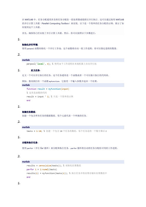
在MATLAB中,任务分配通常涉及将任务分配给一组处理器或线程以并行执行。
这可以通过使用MATLAB 的并行计算工具箱(Parallel Computing Toolbox)来实现。
以下是一个简单的任务分配的示例,展示了如何使用这个工具箱。
首先,确保你已经安装了并行计算工具箱。
然后,你可以按照以下步骤进行:1.初始化并行环境:使用parpool函数初始化一个并行工作池。
这个函数将启动一组工作进程,你可以指定进程的数量。
2.matlabparpool('local', 4); % 使用4个工作进程在本地机器上启动并行池1.定义任务:定义一个可以并行执行的任务。
这个任务通常是一个函数或者一个可以独立执行的代码块。
例如,假设我们有一个函数myFunction,它接受一个输入参数并返回一个结果。
matlabfunction result = myFunction(input)% 这里是函数的代码result = input * 2; % 只是一个简单的示例end1.创建任务数组:创建一个包含所有任务的数据数组。
每个元素代表一个单独的任务。
2.matlabtasks = 1:10; % 创建一个包含10个任务的数组,每个任务是将一个数字乘以21.分配和执行任务:使用parfor(并行for循环)来分配和执行任务。
parfor循环将自动将任务分配给可用的工作进程。
2.matlabresults = zeros(size(tasks)); % 初始化结果数组parfor i = 1:numel(tasks)results(i) = myFunction(tasks(i)); % 执行任务并将结果存储在结果数组中end1.关闭并行池:完成任务后,使用delete函数关闭并行池。
2.matlabdelete(gcp); % 关闭当前并行池1.查看结果:最后,你可以查看results数组来检查任务的结果。
matlab教程ppt(完整版)

`int8()`,
`char()`, `logical()`等。
流程控制结构
顺序结构
按照代码的先后顺序执行 。
选择结构
通过条件语句实现分支选 择,包括`if`、`else`、 `elseif`等。
循环结构
通过循环语句实现重复执 行代码块,包括`for`、 `while`等。
函数编写
函数定义
使用`function`关键字定义函数, 指定输入和输出参数。
介绍MATLAB中的机器学习工具箱,包括工具箱中的函数、算 法和使用方法等。
通过实际案例演示如何使用MATLAB进行机器学习,包括数据 预处理、特征选择、模型训练和评估等。
THANKS
[ 感谢观看 ]
信号的傅里叶变换
介绍傅里叶变换的基本原理 ,以及如何使用MATLAB进 行信号的傅里叶变换和逆变 换。
滤波器设计
介绍滤波器的基本原理和设 计方法,以及如何使用 MATLAB进行滤波器的设计 和实现。
信号处理实例
通过实际案例演示如何使用 MATLAB进行信号处理,包 括信号的频谱分析、滤波、 降噪等。
数值计算基础
数值类型
介绍MATLAB中的数值类型,包括双精度、单精 度、复数等。
变量声明
解释如何声明和初始化变量,以及如何使用 MATLAB的数据类型。
运算符
介绍基本的算术运算符、关系运算符和逻辑运算 符及其用法。
方程求解
代数方程求解
介绍如何使用MATLAB求解一元和多元代数方程。
微分方程求解
介绍如何使用MATLAB求解常微分方程和偏微分方程。
MATLAB应用领域
MATLAB是一种用于算法开发、数据 可视化、数据分析和数值计算的高级 编程语言和交互式环境。
[整理]MATLAB、Simulink、Power System工具箱简介.
![[整理]MATLAB、Simulink、Power System工具箱简介.](https://img.taocdn.com/s3/m/513d18aabb4cf7ec4afed078.png)
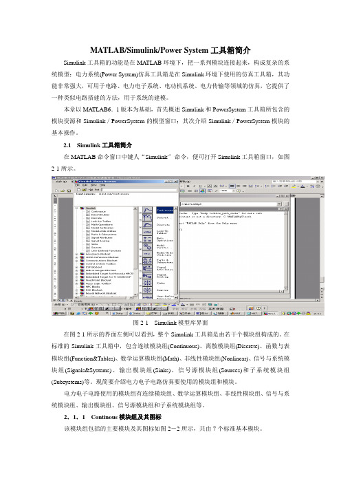
MATLAB/Simulink/Power System工具箱简介Simulink工具箱的功能是在MATLAB环境下,把一系列模块连接起来,构成复杂的系统模型;电力系统(Power System)仿真工具箱是在Simulink环境下使用的仿真工具箱,其功能非常强大,可用于电路、电力电子系统、电动机系统、电力传输等领域的仿真,它提供了一种类似电路搭建的方法,用于系统的建模。
本章以MA TLAB6.1版本为基础,首先概述Simulink和PowerSystem工具箱所包含的模块资源和Simulink/PowerSystem的模型窗口;其次介绍Simulink/PowerSystem模块的基本操作。
2.1 Simulink工具箱简介在MA TLAB命令窗口中键人“Simulink'’命令,便可打开Simulink工具箱窗口,如图2-1所示。
图2-1 Simulink模型库界面在图2-1所示的界面左侧可以看到,整个Simulink工具箱是由若干个模块组构成的。
在标准的Simulink工具箱中,包含连续模块组(Continuous)、离散模块组(Discrete)、函数与表模块组(Function&Tables)、数学运算模块组(Math)、非线性模块组(Nonlinear)、信号与系统模块组(Signals&Systems)、输出模块组(Sinks)、信号源模块组(Sources)和子系统模块组(Subsystems)等。
现简要介绍电力电子电路仿真要使用的模块组和模块。
电力电子电路使用的模块组有连续模块组、数学运算模块组、非线性模块组、信号与系统模块组、输出模块组、信号源模块组和子系统模块组等。
2.1.1 Continous模块组及其图标该模块组包括的主要模块及其图标如图2-2所示,共由7个标准基本模块。
图2-2 Continous模块组2.1.2 Math Operations模块组及其图标该模块组包括的主要模块及其图标如图2-3所示,共由25个标准基本模块。
matlab教程ppt(完整版)

控制流语句
使用条件语句(如if-else)和 循环语句(如for)来控制程序 流程。
变量定义
使用赋值语句定义变量,例如 `a = 5`。
矩阵运算
使用矩阵进行数学运算,如加 法、减法、乘法和除法等。
函数编写
创建自定义函数来执行特定任 务。
02
MATLAB编程语言基础
变量与数据类型
变量命名规则
数据类型转换
编辑器是一个文本编辑器 ,用于编写和编辑 MATLAB脚本和函数。
工具箱窗口提供了一系列 用于特定任务的工具和功 能,如数据可视化、信号 处理等。
工作空间窗口显示当前工 作区中的变量,可以查看 和修改变量的值。
MATLAB基本操作
数据类型
MATLAB支持多种数据类型, 如数值型、字符型和逻辑型等 。
04
MATLAB数值计算
数值计算基础
01
02
03
数值类型
介绍MATLAB中的数值类 型,包括双精度、单精度 、复数等。
变量赋值
讲解如何给变量赋值,包 括标量、向量和矩阵。
运算符
介绍基本的算术运算符、 关系运算符和逻辑运算符 及其优先级。
数值计算函数
数学函数
列举常用的数学函数,如 三角函数、指数函数、对 数函数等。
矩阵的函数运算
总结词:MATLAB提供了许多内置函 数,可以对矩阵进行各种复杂的运算
。
详细描述
矩阵求逆:使用 `inv` 函数求矩阵的 逆。
特征值和特征向量:使用 `eig` 函数 计算矩阵的特征值和特征向量。
行列式值:使用 `det` 函数计算矩阵 的行列式值。
矩阵分解:使用 `factor` 和 `expm` 等函数对矩阵进行分解和计算指数。
matlab demo用法 -回复
matlab demo用法-回复Matlab是一种广泛应用于科学和工程领域的高级编程语言和环境。
它的灵活性和强大的数学计算能力使得其成为了研究人员和工程师的首选工具。
在本篇文章中,我们将深入探讨Matlab Demo的用法,介绍它的基本概念、操作步骤以及一些常见的应用场景。
什么是Matlab Demo?Matlab Demo是Matlab的一个重要功能,用于展示和演示程序的工作方式。
它可以通过交互式的界面展示Matlab程序的主要功能和特点,帮助用户更好地理解和实践代码。
Demo可以包含代码、图形、动画、解释文本等元素,使得整个过程更加生动有趣。
Matlab Demo不仅可以用于教学和学习,还可以用于技术演示和项目展示等。
使用Matlab Demo的步骤:在正式介绍Matlab Demo的用法之前,我们首先要安装和启动Matlab 软件。
确保您已经正确安装了Matlab并成功地启动了它。
然后,按照以下步骤来使用Matlab Demo:步骤一:打开Matlab软件后,您会看到一个命令窗口。
在命令窗口中,输入以下命令,打开Matlab Demo窗口:demo按下回车键后,Matlab Demo窗口将会弹出。
步骤二:在Matlab Demo窗口中,您可以浏览不同的Demo主题。
Demo 主题按照不同的领域进行分类,例如数学、信号处理、图形等。
选择一个您感兴趣的主题,点击它的标题即可开始。
步骤三:进入Demo主题后,界面会显示出该主题的说明和内容。
您可以浏览Demo的代码,了解程序的工作方式。
点击“Run”按钮,Matlab 将会执行Demo程序并输出结果。
您可以观察程序的运行情况,学习Matlab的编程技巧。
步骤四:除了运行Demo程序,您还可以进行一些交互操作。
例如,您可以修改代码的一些参数或输入一些数据,观察对程序的影响。
这种交互性的操作可以帮助您更深入地理解程序的运行原理。
步骤五:在Demo窗口中,您还可以找到一些额外的资源和参考资料。
多无人机任务分配算法与仿真matlab

多无人机任务分配算法与仿真MATLAB一、概述无人机(UAV)作为一种无人驾驶的航空器,其在军事侦察、灾难救援、农业植保等领域具有广泛的应用前景。
随着技术的不断发展,无人机系统越来越复杂,单一无人机已经不能满足大范围任务的需求。
多无人机系统成为了未来发展的趋势。
在多无人机系统中,任务分配算法是至关重要的一环,它直接影响到无人机的效率和性能。
本文将介绍多无人机任务分配算法,并利用MATLAB进行仿真实验。
首先我们将简要介绍多无人机系统的任务分配问题,然后详细探讨多种任务分配算法,并使用MATLAB对这些算法进行仿真模拟。
最后我们将对仿真结果进行分析,总结出各种算法的优缺点。
二、多无人机任务分配问题在多无人机系统中,任务分配是指将一组任务分配给多个无人机,以便尽快地完成这些任务。
任务分配问题通常包括以下几个方面的考虑:1. 任务属性:每个任务可能有不同的属性,如优先级、难度等。
无人机需要根据任务属性来选择执行的任务。
2. 无人机属性:不同的无人机可能具有不同的飞行能力和载荷能力,需要根据任务属性来选择执行的无人机。
3. 通信和协同:多个无人机之间需要进行通信和协同,以便更好地执行任务。
三、多无人机任务分配算法针对多无人机任务分配问题,目前存在多种算法,下面我们将介绍几种常见的算法。
1. 贪婪算法贪婪算法是一种简单、直观的任务分配算法。
该算法会根据任务属性和无人机属性,选择当前最合适的任务-无人机配对,然后进行分配。
这种算法快速、简单,适用于一些简单的场景,但在复杂任务和多无人机系统中效果不佳。
2. 遗传算法遗传算法是一种启发式算法,通过模拟生物遗传学中的遗传和进化过程,来寻找最优解。
在多无人机任务分配中,遗传算法可以根据任务和无人机的属性,不断演化出最适合的任务-无人机配对,从而实现高效的任务分配。
3. 蚁裙算法蚁裙算法是一种模拟蚂蚁寻找食物的行为,来解决优化问题的算法。
在多无人机任务分配中,蚁裙算法可以模拟蚂蚁在任务和无人机之间寻找最优路径的行为,从而找到最优的任务-无人机配对。
MATLAB、Simulink、Power System工具箱简介
MATLAB/Simulink/Power System工具箱简介Simulink工具箱的功能是在MATLAB环境下,把一系列模块连接起来,构成复杂的系统模型;电力系统(Power System)仿真工具箱是在Simulink环境下使用的仿真工具箱,其功能非常强大,可用于电路、电力电子系统、电动机系统、电力传输等领域的仿真,它提供了一种类似电路搭建的方法,用于系统的建模。
本章以MA TLAB6.1版本为基础,首先概述Simulink和PowerSystem工具箱所包含的模块资源和Simulink/PowerSystem的模型窗口;其次介绍Simulink/PowerSystem模块的基本操作。
2.1 Simulink工具箱简介在MA TLAB命令窗口中键人“Simulink'’命令,便可打开Simulink工具箱窗口,如图2-1所示。
图2-1 Simulink模型库界面在图2-1所示的界面左侧可以看到,整个Simulink工具箱是由若干个模块组构成的。
在标准的Simulink工具箱中,包含连续模块组(Continuous)、离散模块组(Discrete)、函数与表模块组(Function&Tables)、数学运算模块组(Math)、非线性模块组(Nonlinear)、信号与系统模块组(Signals&Systems)、输出模块组(Sinks)、信号源模块组(Sources)和子系统模块组(Subsystems)等。
现简要介绍电力电子电路仿真要使用的模块组和模块。
电力电子电路使用的模块组有连续模块组、数学运算模块组、非线性模块组、信号与系统模块组、输出模块组、信号源模块组和子系统模块组等。
2.1.1 Continous模块组及其图标该模块组包括的主要模块及其图标如图2-2所示,共由7个标准基本模块。
图2-2 Continous模块组2.1.2 Math Operations模块组及其图标该模块组包括的主要模块及其图标如图2-3所示,共由25个标准基本模块。
- 1、下载文档前请自行甄别文档内容的完整性,平台不提供额外的编辑、内容补充、找答案等附加服务。
- 2、"仅部分预览"的文档,不可在线预览部分如存在完整性等问题,可反馈申请退款(可完整预览的文档不适用该条件!)。
- 3、如文档侵犯您的权益,请联系客服反馈,我们会尽快为您处理(人工客服工作时间:9:00-18:30)。
实验1 MATLAB仿真平台熟悉2(学时)实验2 动态仿真集成环境-Simulink熟悉(任务分配附后)2(学时)实验3 SPWM仿真实现2(学时)实验4 电机建模与仿真2(学时)《系统仿真》实验2 各班同学具体任务分配MATLAB/SIMULINK/ power system demo理解要求:(1)理解模型个各组成模块(反推导出数学公式);(2)应用场合;(3)根据实际生产现场,进行相关仿真实验;(4)对实验结果进行分析(含使用FFT Analysis During Simulation分析输入输出谐波);(5)根据中国国情进行模型修改(如将电网交流电压从60Hz, 110V改为50Hz, 220V) (6)写上班级、学号、姓名。
A4排版,检查无误后,打印,交纸质件1份,电子文档1份,由各班课代表汇总,11周交任课老师。
(7)其他3个实验FFT Analysis During Simulation频谱分析工具大家共用(分析输入输出谐波)P.Dahler, ABB® Turgi1. Switching an Inductive Circuit Using a Breaker With no Snubber10自动化1 石惠文潘亚辉This example illustrates the Ideal Switching device solution method of the Powergui block.G. Sybille (Hydro-Quebec)2. Steady-State Analysis of a Linear Circuit10自动化1 金紫君卢佩This demonstration illustrates use of the Powergui and Impedance Measurement blocks to analyze the steady-state operation of a linear electrical circuitG. Sybille (Hydro-Quebec)3. Transient Analysis of a Linear Circuit10自动化1 周洋李能慧This demonstration illustrates steady-state and transient simulation of a linear circuit and use of the Powergui blockH. Le-Huy (Universite Laval, Quebec) and G. Sybille (Hydro-Quebec)4. Three-Winding Distribution Transformer10自动化1 邹叶刘颖This demonstration illustrates the use of the linear transformer to simulate a three-winding distribution transformer rated 75 kVA - 14400/120/120 V.G. Sybille (Hydro-Quebec)5. Three-Phase Saturable Transformer10自动化1 阳莉莉徐莹莹This demonstration illustrates use of Three-phase, Powergui, and Multimeter blocks to study transformer saturation phenomenonG. Sybille (Hydro-Quebec)6.Three-Phase Core-Type Transformer10自动化1 祁梦云孙雪涵This demo illustrates use of the Three-Phase Transformer Inductance Matrix Type block to model a three-phase core-type saturable transformer. It also demonstrates that using three single-phase transformers to simulate a Yg/Yg core-type transformer is not acceptable. Gilbert Sybille (Hydro-Quebec, IREQ)7. Current Transformer Saturation10自动化1 唐朝勇陈治强This demonstration illustrates measurement distortion due to saturation of a current transformer (CT)G. Sybille (Hydro-Quebec)8. Use of Surge Arresters in Transmission System10自动化1 林勇谭冬烨This demonstration illustrates use of surge arresters in a series and shunt compensated 735 kV AC transmission systemG. Sybille (Hydro-Quebec)9. Single Phase Line - Time and Frequency Domain Testing10自动化1 丁钉邓俊杰This demonstration compares time domain and frequency domain performance of distributed parameter line model and PI section line modelG. Sybille (Hydro-Quebec)10. Three-Phase Line (DPL and PI Section) - Single-Phase Energization10自动化1 夏亚兵熊伟This demonstration compares transients obtained with a distributed parameter line model and a PI section line modelG. Sybille (Hydro-Quebec)11. Computation of R L and C Cable Parameters10自动化1 谢科袁宇Use of power_cableparam function to calculate R,L, and C cable parameters.Joseph Duron Schweizerische Bundesbahnen SBB Infrastruktur Energie Systemdesign12. Dynamic Load and Programmable Voltage Source10自动化1 刘苗阳建This example illustrates use of the 3-Phase Dynamic Load and 3-Phase Programmable Voltage Source blocksG. Sybille (Hydro-Quebec)13. Single Phase Dynamic Load Block10自动化1 黄浩彭波This example illustrates an example of a single-phase dynamic load block built with Simulink® blocks.Graham Dudgeon, Senior Consultant, The MathWorks™ Ltd14. Saturable Transformer with Hysteresis10自动化1 彭超贺如洋This demonstration illustrates simulation of hysteresis in a saturable transformer S. Casoria (Hydro-Quebec) and P. Brunelle (TransEnergie)15. Cassie and Mayr Arc Models for a Circuit Breaker10自动化1 李凌全袁慎溪P.H. Schavemaker, Power Systems Laboratory, Delft University of Technology, the Netherlands. P.H.Schavemaker@its.tudelft.nlIntroduction This demonstration illustrates use of the Cassie and Mayr arc model for simulating high voltage circuit breaker interruption16.Variable Inductance Modeling10自动化1 任一思谭有志Look under the mask of the Variable Inductance block to see how the model is implemented17. Interfacing Simulink® Models with SimPowerSystems™10自动化1 甘飞朱晔IntroductionIn this demo, we use the Synchronous machine blocks as an example to show the interfaces between Simulink® and SimPowerSystems™. There are two similar circuits shown in parallel. The top circuit model shows the starting of a a synchronous machine using blocks from the SimPowerSystems library. The circuit below it is identical in all respects, but for a custom-built model of the Synchronous machine.18.Six-Pulse Cycloconverter10自动化1 谢海鹏滕浩This demonstration illustrates a six-pulse cycloconverter driving a static load.Graham Dudgeon, Senior Consultant, The MathWorks™ I nc. Igor Braverman, Senior Consultant, The MathWorks™ Inc.19.Speed Control of a DC Motor Using BJT H-Bridge10自动化1 陈佳蕾徐坤This demonstration illustrates simulation of a H bridge used to generated a chopped voltage and control speed of a DC motor, in open loop, in both directions.Gilbert Sybille (Hydro-Quebec)20.Zener Diode Regulator10自动化1 张慧林龙幸开This example presents a model of the zener diode used in a voltage regulator10自动化2 杨柳茂刘芳This demonstration illustrates use of the Ideal Switching Device solution method to simulate a full wave rectifier using ideal diodes.G. Sybille (Hydro-Quebec)22.Single-Phase Rectifier10自动化2 朱玲易琪This demonstration illustrates use of the Universal Bridge, Multimeter, and Discrete System blocks G. Sybille (Hydro-Quebec)10自动化2 周葱向玲This demonstration illustrates the use of the Diode block to simulate a three-phase rectifier and compares continuous vs. discrete simulations G. Sybille (Hydro-Quebec)24.Three-Phase Thyristor Converter10自动化2 李彬艳魏雪环This demonstration illustrates the use of the Universal Bridge block to simulate athree-phase six-pulse converter and harmonic analysis using the Powergui/FFT tool.H. Le-Huy (Universite Laval, Quebec)25.Ideal Switch - Inductive Current Chopping10自动化2 郭箫吟隋永波This example illustrates the effect of current chopping in an inductive circuitG. Sybille (Hydro-Quebec)26.MOSFET Converter10自动化2 胡旋邓仲全This example illustrates the use of the MOSFET in a Zero-Current Quasi-Resonant Switch converter K. Al-Haddad (Ecole de Technologie Superieure, Montreal)27.GTO Buck Converter10自动化2 童斌肖栋才This example illustrates the use of the GTO-thyristor in the buck converter topology28.Single-Phase PWM Inverter10自动化2 谭佳谭卓This demonstration illustrates use of the IGBT/Diode block in voltage-sourced converters. It also demonstrates harmonic analysis of PWM waveforms using the Powergui/FFT tool. G. Sybille (Hydro-Quebec)29.DC/DC and DC/AC PWM Converters10自动化2 赵拔秦铭阳This demonstration illustrates use of the Universal Bridge and Discrete PWM Pulse Generator blocks. It also demonstrates harmonic analysis of PWM waveforms using the Powergui/FFT tool.G. Sybille and P. Giroux (Hydro-Quebec)30.Three-Phase Two-Level PWM Converters10自动化2 姜宇李文捷This demonstration illustrates use of the Universal Bridge and Discrete PWM Pulse Generator blocks. It also demonstrates harmonic analysis of PWM waveforms using the Powergui/FFT tool. G. Sybille and P. Giroux (Hydro-Quebec)31.AC/DC Three-Level PWM Converter10自动化2 陈宇郭敏This AC-DC Converter demo illustrates the operation of the Three-Level Bridge block. P. Giroux ; G. Sybille Hydro-Quebec (IREQ)32.Three-Phase SV-PWM Converter10自动化2 黄帅戚保林Open-loop speed control of an induction motor using constant V/Hz principle and a space vector (SV) PWM technique. Pierre Giroux, Hydro-Quebec (IREQ)33.Five-Cell Multi-Level Converter10自动化2 杨帆尹卷This demonstration illustrates a five-cell multi-level converter driving a static load. Graham Dudgeon, Senior Consultant, The MathWorks™ Inc.34.Multilevel Multiphase Space-Vector PWM10自动化2 赵弈博任义Oscar Lopez, Jacobo Alvarez, Jesus Doval-Gandoy and Francisco Freijedo, Electronics Technology Department University of Vigo, Spain. olopez@uvigo.es35.Three-Phase Three-Level PWM Converter10自动化2 杨月任云华This demonstration illustrates simulation of a three-phase, three-level inverter and discrete three-phase PWM generator. It also demonstrates harmonic analysis of PWM waveforms using the Powergui/FFT tool.P. Giroux and G. Sybille (Hydro-Quebec))36.Two-Level PWM Converter and Dead Time10自动化2 彭辉忠吴昊This demonstration illustrates impact of dead time on harmonic distortion of a two-level converter used in a 50 kW microturbine.G. Sybille (Hydro-Quebec)37.Neutral Point Clamp Inverter and Dead Time10自动化2 姚滋纲欧思程This demonstartion simulates dead time and semiconductor failure inside a three-level PWM converter. G. Sybille Hydro-Quebec (IREQ)38.Three-Phase 48-Pulse GTO Converter10自动化3 尹榕慧熊笑This demonstration illustrates use of three-level converters and zig-zag phase-shifting transformers in a 48-pulse square-wave GTO converter. It also demonstrates harmonic analysis using the Powergui/FFT tool. P. Giroux and G. Sybille (Hydro-Quebec))39.AC-DC-AC PWM Converter10自动化3 李佳妮任索This example of AC-DC-AC converter illustrates use of Universal Bridge, Multimeter, and Powergui blocks, as well as discrete control blocks of the Extras library.G. Sybille (Hydro-Quebec)40.Three-Phase Matrix Converter10自动化3 周俊高张艳This demonstration illustrates a three-phase matrix converter driving a static load and drawing unity power factor at the source.Graham Dudgeon, Senior Consultant, The MathWorks™ Ltd41.Chopper-Fed DC Motor Drive (Continuous)10自动化3 周琨黄丽珍Case study: Chopper-Fed DC Motor Drive H. Le-Huy (Universite Laval, Quebec)42.Chopper-Fed DC Motor Drive (Discrete)10自动化3 闵玮奇陈曦Note: This example is similar to the continuous version, but discretization allows faster simulation. H. LeHuy (Universite Laval, Quebec) and G. Sybille (Hydro-Quebec)43.Vector Control of AC Motor Drive10自动化3 唐亚辉罗雅元Case study : Variable-Frequency Induction Motor DriveH. Le-Huy (Universite Laval, Quebec)44. Stepper Motor Drive10自动化3 杨辉伍程灿A hybrid stepper motor drive. Hoang Le-Huy, Laval UniversityWarning: You need to install the Control System Toolbox in order to run this demo45.Simplified Synchronous Machine - Speed Regulation10自动化3 刘湘宁聂志富This demonstration illustrates the use of the simplified alternator for a load shedding test on a 2000 kVA, 600 V alternator.G. Sybille (Hydro-Quebec)46.Synchronous Machin e10自动化3 吴昊伍强胜This demonstration illustrates use of the synchronous machine associated with the Hydraulic Turbine and Governor (HTG) and Excitation System blocks and use of the Load Flow to initialize machine currentsLouis-A. Dessaint and R. Champagne (Ecole de Technologie Superieure, Montreal)47.Starting a Synchronous Motor10自动化3 姚星宇王梓航This demo illustrates the starting procedure for a synchronous motor.Richard Gagnon (Hydro-Quebec)48.Mechanical Coupling of Synchronous Generator with Exciter System10自动化3 刘仲范吴元凯This demonstration illustrates a Machine mechanical coupling of an excitation system. Gilbert Sybille, IREQ.10自动化3 肖玉龙刘亚星This demonstration illustrates use of the asynchronous machine in an open-loop speed control on a 3 HP 220 V industrial motor.Louis-A. Dessaint and R. Champagne (Ecole de Technologie Superieure, Montreal)50.Saturation in Three-Phase Asynchronous Machine10自动化3 杨立畅梓皓Effects of saturation in a three-phase asynchronous motor at various operating conditions. Jean-Nicolas Paquin and Louis-A. Dessaint (Ecole de Technologic Superiure, Montreal)10自动化3 严煜坤朱茂琨This demonstration illustrates operation of a single phase asynchronous motor in Capacitor-Start and Capacitor-Start-Run operation modes.H. Ouquelle and Louis-A.Dessaint (Ecole de technologie superieure, Montreal)52 Single-Phase Asynchronous Machine - Voltage Control of Auxiliary Winding 10自动化3 谭翔周睿强H.Ouquelle and Louis-A.Dessaint (Ecole de technologie superieure, Montreal)53. Single-Phase Asynchronous Machine - Vector Control of AC Drive10自动化3+兴韩涛别剑芳H.Ouquelle and Louis-A.Dessaint (Ecole de technologie superieure, Montreal)54. Permanent Magnet Synchronous Machine10自动化(兴)卜志威陈俊峰This demonstration illustrates use of the PMSM in a closed-loop speed and current control on a 1.1 kW, 3000 rpm industrial motor.Louis-A. Dessaint and R. Champagne (Ecole de Technologie Superieure, Montreal)55. Starting a DC Motor10自动化(兴)陈俊腾陈泽耀Starting of a 5 HP 240V DC motor with a three-step resistance starter.G. Sybille (Hydro-Quebec)56. Steam Turbine and Governor System - Subsynchronous Resonance10自动化(兴)谌艳华戴吉全This demonstration illustrates subsynchronous resonance (SSR) using the Steam Turbine and Governor on a series-compensated network.R. Champagne and L. Dessaint (Ecole de Technologie Superieure, Montreal)57. Emergency Diesel-Generator and Asynchronous Motor10自动化(兴)侯自亮康楷This demonstration illustrates fault and islanding of an induction motor/diesel-generator system and demonstrates the Machine Load Flow option of the Powergui. (See Chapter 2 of the User's Guide).G. Sybille (Hydro-Quebec)58. Synchronous Machine and Regulator10自动化(兴)李超李健澎Nonlinear control of a hydraulic turbine and a synchronous generator.Aime Francis Okou and Louis-A. Dessaint (Ecole de technologie superieure, Montreal)59. Performance of Three PSS for Interarea Oscillations10自动化(兴)李鹏超李鹏舟This demonstration illustrates the use of the phasor solution by comparing three Power System Stabilizers (PSS) using Kundur's four-machine two-area test system.I. Kamwa (Hydro-Québec) Warning: You need to install the Control System Toolbox in order to run thisdemo60 Switched Reluctance Motor10自动化(兴)李述鹏李文强A current-controlled 60 kW 6/4 SRM drive Hoang Le-Huy, Laval University61. Brushless DC Motor Fed by Six-Step Inverter10自动化(兴)李智廖辉煌This demonstration illustrates the use of a Six-Step Switch-on mode for a trapezoidal PMSM motor rated 1kW, 3000 rpm and speed regulated.Olivier Tremblay, Louis-A. Dessaint (Ecole de technologie superieure, Montreal)62.Single-Phase Series Compensated Network10自动化(兴)罗江欧阳钢This demonstration ilustrates frequency-domain and time-domain analysis of a series-compensated transmission systemG. Sybille (Hydro-Quebec)Contents∙Circuit Description∙Demonstration63. Three-Phase Series Compensated Network10自动化(兴)石志翔汤超This demonstration ilustrates use of three-phase blocks to study transients on aseries-compensated 735-kV transmission system(See case study 'Series Compensated Transmission Network' in the SimPowerSystems™ User's Guide) G. Sybille (Hydro-Quebec)64. Simple 6-Pulse HVDC Transmission System10自动化(兴)唐峰魏石磊This demonstration illustrates steady-state and transient performance of a simple 500 MW (250 kV-2kA) HVDC transmission systemG. Sybille (Hydro-Quebec)65. Three-Phase Harmonic Filter s10自动化(兴)文杰君吴继袁Pierre Giroux (Hydro-Quebec)In HVDC installations, AC harmonic shunt filters are used to:1) reduce harmonic voltages and currents in the power system,2) supply the reactive power consumed by the converter. To illustrate these concepts, a 1000-MW (500 kV, 2kA) HVDC rectifier is simulated.66. Three-Phase Active Harmonic Filter10自动化(兴)吴炜楠阳波This demonstration illustrates the use of a shunt active harmonic filter (AHF) to minimize the harmonic content propagated to the source from a non-linear load.Graham Dudgeon, Senior Consultant, The MathWorks™ Ltd67. Three-Phase Line - Single-Pole Reclosing10自动化(兴)于旭凯袁武This demonstration ilustrates the use of three-phase blocks to study phase-to-ground fault and single-pole reclosing of a 735-kV transmission line G. Sybille (Hydro-Quebec)68. Sequence and abc_to_dq0 Transformation s10自动化(兴)章时源周健文This demonstration ilustrates use of the Three-Phase Programmable Source, abc_dq0, and Sequence Analyzer blocksG. Sybille (Hydro-Quebec)69. Three-Phase Programmable Source, V-I Measurement and Sequence Analyzer 10自动化(兴)周子涵朱鸿章This demonstration ilustrates use of the 3-Phase Programmable Voltage Source, 3-Phase V-I Measurement, and Sequence Analyzer blocksG. Sybille (Hydro-Quebec)70. Three-Phase Programmable Source, PLL, Voltage and Power Measurement 10自动化自由加选This demonstration ilustrates use of the 3-Phase Programmble Voltage Source, PLL and Variable-Frequency Positive-Sequence Voltage and Power Measurement blocksG. Sybille and P. Giroux (Hydro-Quebec)。