过压保护器说明书
BSTG-B-12.7-600 过电压保护器 技术说明书

197
□-J-13.8
16.7
13.8
34.5
31~41.4
46.8
55
55
180
260
□-J-15.75
19
15.75
39.3
35.3~47.2
53.3
62.5
62.5
240
360
□-Z-3.8/12
变
压
器
开
关
母
线
3.8
3
7
6.3~8.4
10.2
12
12
400/
600
131
182
3
□-Z-7.6/19
V1、V2-电压表A1-数字电流表ZT-调压器ST-试验变压器
LJ-电流继电器R-限流电阻
按原理图将相关仪表和设备连接好。测试前应首先将电流继电器LJ的整定值调至最小值(作为后备保护),然后将试验变压器空载升压,电流继电器LJ应不动作,将数字电流表A1的量程调至5~20A(5KVA及以下容量试验变压器可不加限流电阻R)。
⑷安装时严禁手提电缆.同时要注意避免高压电缆被锐器割破。
3.用氧化锌非线性电阻和放电间隙的结构,使两者互为保护。放电间隙使氧化锌电阻的荷电率为零,氧化锌电阻的非线性特性又使放电间隙动作后无续流,放电间隙不再承担灭弧任务,提高了产品的使用寿命。
4.电压冲击系数为1,在各种电压波形下放电电压值相等,不受各种操作过电压波形影响。过电压保护值准确,保护性能优良。
3、□在和三相电源(A、B、C)及接地端(D)相连时,须注意以下事项:
⑴电缆外端裸露的连接线鼻子相互之间距离,应满足不同电压等级的不同相带电导体之间保持的最小安全距离的要求;
过压保护设备说明书

Description–Overload protection – trip class 10A–Phase loss sensitivity–Disconnect function–Temperature compensation from -25 … +50 °C –Adjustable current setting for overload protection –Suitable for three- and single-phase application –Trip-free mechanism–Clear switch position indication ON/OFF Order dataMS325 screw terminalSettingrangeAType TripclassOrder code Pack-ing unitPCEWeightper PCEkg0.10...0.16MS325-0.1610A1SAM150000R100110.310 0.16...0.25 MS325-0.2510A1SAM150000R100210.310 0.25...0.40MS325-0.410A1SAM150000R100310.310 0.40...0.63 MS325-0.6310A1SAM150000R100410.3100.63...1.00 MS325-110A1SAM150000R100510.3401.00...1.60 MS325-1.610A1SAM150000R100610.3701.60...2.50 MS325-2.510A1SAM150000R100710.3702.50...4.00 MS325-410A1SAM150000R100810.370 4.00...6.30 MS325-6.310A1SAM150000R100910.370 6.30...9.0 MS325-910A1SAM150000R101010.370 9.00...12.5 MS325-12.510A1SAM150000R101110.370 12.5...16.0 MS325-1610A1SAM150000R101210.370 16.0...20.0 MS325-2010A1SAM150000R101310.370 20.0...25.0 MS325-2510A1SAM150000R101410.370Note: MS325 with pre-assembled auxiliary contact HKF1-11,please order as follow 1SAM150005R0xxxManual motor starters are electro-mechanical protection devices for the main circuit. They are used mainly to switch motors manually ON/OFF and protect them fuse less against short-circuit, overload and phase failures.Fuse less protection with a manual motor starter saves costs, space andensures a quick reaction under short-circuit condition, by switching off the motor within milliseconds. Fuse less starter combinations are setup together with contactors.2 C D C 2 4 1 5 0 0 S 0 0 0 92 - 2CDC131046D0201Functional description2C D C 242008F 001312341 Terminals 1L1, 3L2, 5L32 Test function3 Current setting rangeAdjustable current setting for overload protection 4 Terminals 2T1, 4T2, 6T3ApplicationThe manual motor starters protect the load and the installation against short-circuit and overload. They are three pole protection devices with thermal tripping elements for overload protection and electromagnetic tripping elements for short-circuit protection. Furthermore, they provide a disconnect function for safely isolation of the installation and the supply and can be used for the manual switching of loads.The manual motor starters have a setting scale in amperes, which allows the direct adjusting of the device without anyadditional calculation. In compliance with international and national standards, the setting current is the rated current of the motor and not the tripping current (no tripping at 1.05 x I, tripping at 1.2 x I; I = setting current).Operation modeSingle-phase operation Three-phase operationWiring diagramResistance and power loss per poleType Setting range Resistance per pole Power loss per polelower value A upper valueAΩat lower valueWat upper valueWMS325-0.160.100.1671.100.7 1.8 MS325-0.250.16 0.25 27.100.7 1.7 MS325-0.40.250.4012.300.8 2.0 MS325-0.630.40 0.63 5.170.8 2.1 MS325-10.63 1.00 2.0900.8 2.1 MS325-1.6 1.00 1.60 0.8050.8 2.1 MS325-2.5 1.60 2.50 0.3400.9 2.1 MS325-4 2.50 4.00 0.1410.9 2.3 MS325-6.3 4.00 6.30 0.0510.8 2.0 MS325-9 6.30 9.0 0.0220.9 1.8 MS325-12.59.00 12.5 0.012 1.0 1.8 MS325-1612.5 16.0 0.007 1.0 1.7 MS325-2016.0 20.0 0.004 1.0 1.6 MS325-2520.0 25.0 0.003 1.1 1.7 Technical diagramIntermittent periodic duty, ta: Motor starting timeDimensionsin mm /inches MS325MS325 with HK-F112CDC131046D0201 - 34 - 2CDC131046D0201Technical data IEC/ENData at T A = 40 °C and at rated values, if nothing else indicated Main circuitMS325Rated operational voltage U e690 V AC 440 V DCSetting range - thermal overload protection see table “Order data” on page 1Rated operational current I esee table belowRated operational current DC-5 I e3 conducting paths in series up to 250 Vsee “Rated operational current I e ”Rated instantaneous short-circuit current setting I i see table belowRated service short-circuit breaking capacity I cs see table “Short-circuit breaking capacity and back-up fuses” on page 8Rated ultimate short-circuit breaking capacity I cu Rated service short-circuit breaking capacity DC I cs 3 conducting paths in series up to 250 V on requestTrip classsee table “Order data” on page 1Rated frequency DC, 50/60 Hz Number of poles 3Resistance per pole see table “Resistance and power loss per pole” on page 3Power loss per poleIsolation dataRated impulse withstand voltage U imp 6 kV Rated insulation voltage U i 690 V Pollution degree3Electrical connection MS325Connecting capacitysolid 1/2 x 1 ... 6 mm²stranded1/2 x 1 ... 6 mm²flexible with ferrule1/2 x 0.75 ... 4 mm²flexible with ferrule insulated 1/2 x 0.75 ... 4 mm²flexible without ferrule1/2 x 1 ... 6 mm²Stripping length 10 mm Tightening torques 1.4 Nm Connection screwM3.5 (Pozidriv 2)TypeRated instantaneousshort-circuit current setting l i Rated operational current l e AA MS325-0.16 1.560.16MS325-0.25 2.440.25MS325-0.4 3.900.40MS325-0.63 6.140.63MS325-111.50 1.00MS325-1.618.40 1.60MS325-2.528.75 2.50MS325-450.00 4.00MS325-6.378.75 6.30MS325-9135.59.00MS325-12.518012.5MS325-1624016.0MS325-2030020.0MS325-2537525.0General dataMechanical durability100000Electrical durability50000Duty time100 %Operating frequency without early tripping up to 15 operations/h or 60 operations/h with40 % duty ratio, if the motor breaking current 6 x Inand the motor starting time does not exceed 1 s Dimensions (W x H x D)see drawing “Dimensions” on page 3Weight see table “Order data” on page 1Mounting DIN-rail (EN 60715)Mounting position position 1-6 (optional for single mounting)Group mounting on requestMinimum distance to other units same type horizontal0 mmvertical100 mmMinimum distance to electrical conductive board horizontal, up to 400 V> 1.5 mmhorizontal, up to 690 V> 1.5 mmvertical75 mmDegree of protection housing / main circuit terminals IP20Utilization category AMaximum operating altitude up to 2000 mMaximum operating frequency 170 cycles/hElectromagnetic compatibilityElectromagnetic compatibility not applicableEnvironmental dataAmbient air temperatureOperation open - compensated-25 ... +50 °Copen-25 ... +50 °Cenclosed (IB325)0 ... +40 °CStorage-50 ... +80 °CAmbient air temperature compensation acc. to IEC/EN 60947-4-1Vibration (sinusoidal) acc. to IEC/EN 60068-2-6 (Fc)5g / 10 ... 150 HzShock (half-sine) acc. to IEC/EN 60068-2-27 (Ea)15g / 11 msStandards / directivesProduct standard IEC/EN 60947–2IEC/EN 60947-4-1IEC/EN 60947-1UL 508, CSA 22.2 No. 14Low Voltage Directive2006/95/ECEMC Directive2004/108/ECRoHS Directive2002/95/EC2CDC131046D0201 - 5Short-circuit breaking capacity and back-up fuseslCSRated service short-circuit breaking capacitylCURated ultimate short-circuit breaking capacityo No back-up fuse required, because short-circuit proof up to 100 kAType230 V AC 400 V AC440 V AC500 V AC690 V ACI CS kA ICUkAgGAICSkAICUkAgGAICSkAICUkAgGAICSkAICUkAgGAICSkAICUkAgGAMS325-0.16100100°100100°100100°100100°100100°MS325-0.25100100°100100°100100°100100°100100°MS325-0.4100100°100100°100100°100100°100100°MS325-0.63100100°100100°100100°100100°100100°MS325-1100100°100100°100100°100100°100100°MS325-1.6100100°100100°100100°100100°100100°MS325-2.5100100°100100°100100°100100°404025 MS325-4100100°100100°100100°606040101040 MS325-6.3100100°100100°7070504040507740 MS325-9100100°100100°5050803030805550 MS325-12.5100100°757580454580272780 4.5 4.550 MS325-16100100°6060100404010025251004450 MS325-20100100°555510035351002222100 3.5 3.550 MS325-25100100°50501253030125202012533506 - 2CDC131046D0201Technical data UL/CSAMain circuitMS325Maximum operational voltage600 VManual motor controller ratings see table “UL 508 — Manual Motor Controller” on page 8 Motor ratings Horse power see table belowFull load amps (FLA) see table belowLocked rotor amps (LRA)see table belowElectrical connection MS325Connecting capacity stranded1/2 x AWG 14 (8)flexible without ferrule1/2 x AWG 14 (8)Stripping length10 mmTightening torques14 lb-inConnection screw M3.5(Pozidriv 2)Motor rating, single phasehp Horse powerFLA Full load ampsLRA Locked rotor ampsType110 ... 120 V AC220 ... 240 V AChp FLA LRA hp FLA LRAMS325-0.16-- 0.160.96MS325-0.25--0.25 1.5MS325-0.4--0.4 2.4MS325-0.63--0.63 3.78MS325-1--16MS325-1.6-1/10 1.5MS325-2.5-1/6 2.2MS325-41/8 3.81/3 3.6MS325-6.31/4 5.81/2 4.9MS325-91/37.218MS325-12.51/29.8212MS325-161162-1/2MS325-201-1/220317.0MS325-25224317.0Motor rating, three phasehp Horse powerFLA Full load ampsLRA Locked rotor ampsType220 ... 240 V AC440 ... 480 V AC550 ... 600 V AC hp FLA LRA hp FLA LRA hp FLA LRAMS325-0.16- 0.160.96- 0.160.96- 0.160.96MS325-0.25-0.25 1.5-0.25 1.5-0.25 1.5MS325-0.4-0.4 2.4-0.4 2.4-0.4 2.4MS325-0.63-0.63 3.78-0.63 3.78-0.63 3.78MS325-1-161/2 1.1101/20.98MS325-1.6- 1.69.63/4 1.612.53/4 1.310MS325-2.51/2 2.2201 2.1151-1/2 2.416MS325-41 4.2302 3.4253 3.925.6MS325-6.31-1/26403 4.8325 6.136.8MS325-92-1/257.6467-1/29.050.8MS325-12.539.6647-1/211.063.51011.064.8MS325-16515.2921014.0811011.064.8MS325-20515.2921014.0811527.093MS325-257-1/222.01271521.01162035.01162CDC131046D0201 - 7Manual Motor Controller for Motor Disconnect Type Maximum short-circuit current rating480 V600 VkA kAMS325-0.168550MS325-0.258550MS325-0.48550MS325-0.638550MS325-18550MS325-1.68550MS325-2.58550MS325-48550MS325-6.35050MS325-95050MS325-12.55030MS325-165030MS325-205030MS325-255030Manual Motor Controller for Group InstallationType Maximum circuitbreaker perUL/NEC Maximum fusetype (class ...)per UL/NECMaximum short-circuit currentMaximum circuitbreaker perUL/NECMaximum fusetype K5 or RK5per UL/NECMaximum short-circuit current480 V480 V480 V600 V600 V600 VA kA A kAMS325-0.16-1600 (class L)85S7H1200120050 MS325-0.25-1600 (class L)85S7H1200120050 MS325-0.4-1600 (class L)85S7H1200120050 MS325-0.63-1600 (class L)85S7H1200120050 MS325-1-1600 (class L)85S7H1200120050 MS325-1.6-1600 (class L)85S7H1200120050 MS325-2.5-1600 (class L)85S7H1200120050 MS325-4-1600 (class L)85S7H1200120050 MS325-6.3S7H1200600 (class K5)50S7H1200120050 MS325-9S7H1200600 (class K5)50S4H25025050 MS325-12.5S4H250400 (class K5)50S7H1200120030 MS325-16S4H250400 (class K5)50S7H1200120030 MS325-20S4H250400 (class K5)50S4H25025030 MS325-25S4H250400 (class K5)50S4H25025030Self-Protected (Type E) Combination Motor Controller and Tab Conductor ProtectionType UL 508 Self-Protected (Type E)Combination Motor Controllerfor Tap Conductor ProtectionMaximum short-circuit current Maximum short-circuit current480 V480 VkA kAMS325-0.161818MS325-0.251818MS325-0.41818MS325-0.631818MS325-11818MS325-1.61818MS325-2.51818MS325-41818MS325-6.31818MS325-91818MS325-12.51818MS325-161818MS325-201818MS325-2518188 - 2CDC131046D0201ABB STOTZ-KONTAKT GmbH Eppelheimer Straße 8269123 Heidelberg, Germany Phone: +49 (0) 6221 7 01-0Fax: +49 (0) 6221 7 01-13 25E-Mail:*****************.comYou can find the address of your local sales organization on theABB home page/contacts-> Low Voltage Products and Systems Note:We reserve the right to make technical changesor modify the contents of this document withoutprior notice. With regard to purchase orders, the agreed particulars shall prevail. ABB AG doesnot accept any responsibility whatsoever for potential errors or possible lack of information inthis document.We reserve all rights in this document and inthe subject matter and illustrations contained therein. Any reproduction, disclosure to thirdparties or utilization of its contents – in wholeor in parts – is forbidden without prior written consent of ABB AG.Copyright© 2014 ABBAll rights reservedDocumentnumber2CDC13146D21(2.214)Contact us。
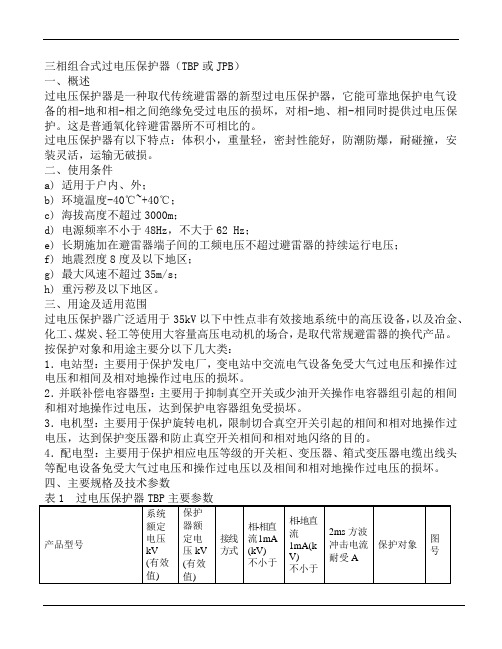
三相组合式过电压保护器产品说明书

三、型号说明
1.保护对象:J-电机;Z-变压器、母线线路、开关;R并联补偿电容器;
O-电机中性点;D-电缆保护器
2.使用环境:W为户外型,无‘W’只适用于户内;
3.附加功能:“J”动作计数器;“IM”过电压检测仪
四、技术参数
1 .用于电机、变压器、开关、母线、线路、电容器等设备过电压保护器。
三相组合式过电压保护器
(TBP-B-42/280)
使
用
说
明
书
醴陵代言电气有限公司
一、产品用途
三相组合式过电压保护器(TBP-B-42/280)是一种新型的过电压保护器,它主要应用于发电、供电和企业的用电系统中,对电机、变压器、开关、母线、电容器等电气设备,除了限制大气过电压保护外,同时也可限制电力系统的操作过电压,对相间和相对地的过电压,均能起到可靠的限制作用。
3、TBP-B-42/280在和三相电源(A、B、C)及接地端(D)相连时,须注意以下事项:
⑴电缆外端裸露的连接线鼻子相互之间距离,应满足不同电压等级的不同相带电导体之间保持的最小安全距离的要求;
⑵TBP-B-42/280电缆线之间的安全距离及TBP-B-42/280电缆线与不同相母线(或柜体)之间的安全距离应不小于该型保护器相间距离(应在电缆电缆拉紧状况下);
二、产品结构/特点
三相组合式过电压保护器(TBP-B-42/280)的电气原理如图一所示,图中FR为高能容氧化锌非线形电阻,JX为放电间隙,由于采用对称结构,其中任意三个可分别接入A、B、C三相,另一个接地线。
三相组合式过电压保护器(TBP-B-42/280)的主要特点:
1.通流容量大,适用范围更广;
2.采用四星形接法,可将相间过电压大大降低,保护的可靠性大为提高。
过电压保护继电器

高精度:采用功能强大的微处理器芯片,尤其采用交流采样技术,电压测量精度为±1%,能分别显示
,保证全球通用(不能使用于变频器输出回路)。
使过电压保护继电器的规格大为减少,高可靠:采用独特的三相电源供电技术,即使在极低电压、甚至在缺相情况下,也能保证保护、报警、
相序保护器原理图
相序监测:当过电压保护继电器通电时,如果相序正确并且所有三相带电,继电器吸合。
过欠压保护器原理
缺相保护器原理图
缺相检测:当缺相故障时,继电器断电。
正常工作(无故障)时继电器吸合。
当缺相时立即断电。
电压不平衡保护器原理图
A、B、C:“不平衡”字符闪烁D:“不平衡”字符长亮。
高压保护器使用说明书

GPZB-I微电脑智能综合保护装置说明书目录1 系统综述 (3)1.1 系统概述 (3)1.2 系统特点 (3)1.3 系统构成 (4)2 产品特点 (5)3 技术指标 (5)3.1 工作环境要求 (5)3.2 功率消耗 (5)3.3 主要保护功能配置 (5)4 保护原理 (6)4.1 速断保护 (6)4.2 零序过流保护 (6)4.3 过电压保护 (7)4.4 过载反时限保护 (7)4.5 低电压保护 (8)4.6 绝缘监视保护 (9)4.7 三相不平衡 (9)5 人机对话操作说明 (9)5.1 人机对话简介 (9)5.2 主菜单说明 (10)5.3 测量数据 (11)5.4 定值整定 (12)5.5 保护功能整定及解释 (12)5.6 密码管理 (16)5.7 事件查询 (17)5.8 试验项目 (17)5.9 附加功能 (18)5.10 出厂设置 (20)6 关于B相电流 (20)6.1 只对开关A相通电流 (21)6.2 只对开关C相通电流 (21)6.3 A相、C相同时通电流(接线方式1) (22)6.4 A相、C相同时通电流(接线方式2) (22)7 关于485通讯 (23)8 关于CAN通讯(选配) (23)9 用户安装调试、维护说明 (23)注意事项 (23)10 常见故障排查 (24)11 航插(26芯)引脚说明 (24)附件:产品接线图1、系统综述1.1 系统概述煤矿井下高压供电系统线路短、多级变电所级联,高压供电线路的布线特点使得常规继电保护装置不能通过整定值和时间级差的方式有选择的跳开故障点开关,出现“越级跳闸”问题。
我们根据煤矿井下高压供电线路的实际情况,采用全系统智能零时限防越保护方式,以辐射型高速通讯网络实现上下级继电保护装置的配合,为井下的高压供电系统的每台高爆开关提供可靠、全时、动态、高速的防越信息通道,每一台开关不再独立运行,而是以相同的节拍成为防越保护系统一部分,基于全站的防越保护系统提高了高压供电线路的可靠性和故障动作时间的实时性。
三相组合式过电压保护器说明书

三相组合式复合外套金属氧化物避雷器产品简介西安神电电器有限公司中国·西安目录三相组合式复合外套金属氧化物避雷器1、概述 (1)2、产品型号说明 (1)3、正常使用条件 (2)4、主要技术参数 (2)5、外形结构及安装尺寸 (4)6、接线方式……………………………………………………………………………10带放电记录仪三相组合式复合外套金属氧化物避雷器1、概述 (11)2、产品型号说明 (11)3、主要技术参数 (11)4、外形结构及安装尺寸 (12)12 5、接线方式…………………………………………………………………………极间过电压保护器1、概述 (13)2、主要技术参数 (13)3、接线方式……………………………………………………………………………13预防性检测及用户须知1、预防性检测 (14)2、用户须知 (15)三相组合式复合外套金属氧化物避雷器一、概述三相组合式复合外套金属氧化物避雷器在对相地之间的过电压提供保护的同时,又对相间过电压提供保护。
本产品结构新颖,外形组合灵活多变,有效的利用和缩减了使用空间。
技术性能合理可靠,保护水平满足 GB 11032-2000《交流无间隙金属氧化物避雷器》、JB/T 10496-2005《交流三相组合式无间隙金属氧化物避雷器》、JB/T ××××-××××《交流三相组合式有串联间隙金属氧化物避雷器》(报批稿)、JB/T 9672.2-2005《交流系统用有串联间隙金属氧化物避雷器》和 DL/T 620-1997《交流电气装置的过电压保护和绝缘配合》的标准要求。
并在国家绝缘子避雷器质量监督检验中心通过了全面的型式试验,已广为电力、石化、铁道、煤碳等系统选用。
二、产品型号说明本产品型号编制方法严格按照 JB/T 8459-1996《避雷器产品型号编制方法》中的 4.2.3.1 条“三相组合式金属氧化物避雷器”标准要求编制,具体如下:外形结构(代号)征数字设计序号使用场所结构特征(kA)产品型式:YH—表示复合外套金属氧化物避雷器结构特征:W—表示无间隙C—表示串联间隙使用场所:S—表示配电用R—表示并联补偿电容器用Z—表示电站用D—表示电机用特征数字:○1 表示相-相的特征数字○2 表示相-地的特征数字外形结构:A—表示A 型B—表示B 型 C—表示C 型J—表示带放电记录仪三、正常使用条件a. 适用于户内、外;b. 环境温度-40℃~+40℃;c. 海拔高度不超过2600m;d. 电源频率不小于48Hz,不大于62Hz;e. 长期施加在避雷器端子间的工频电压应不超过避雷器的持续运行电压(无间隙型)或额定电压(带串联间隙型);f. 地震烈度8 度及以下地区;g. 最大风速不超过35m/s; h. 重污秽及以下地区。
监控传感器过压保护设备说明书

1Monitoring RelaysProduct Description•AC/DC over voltage monitoring relay•Selection of measuring range by DIP-switches•Measuring ranges: 2 to 20 VAC/DC, 5 to 50 VAC/DC, 20 to 200 VAC/DC, 50 to 500 VAC/DC, 0.4 to 4 V p AC •Adjustable voltage limit on relative scale •Adjustable hysteresis•Programmable latching at set level•Output: 8 A SPDT relay normally de-energized•For mounting on DIN-rail in accordance with DIN/EN 50 022 (DUA01) or plug-in module (PUA01)•22.5 mm Euronorm housing (DUA01) or 36 mm plug-in module (PUA01)•LED indication for relay and power supply ON •Galvanically separated power supplyType Selection1-Phase AC/DC Over Voltage - AC Over Current Types DUA01, PUA01Input SpecificationsOutput SpecificationsDUA01 and PUA01 are pre-cise AC/DC over voltage monitoring relays. They can also be used as 1-phase or 3-phase over current monitoring relays when connected with MI or MP current transformers.Owing to the built-in latch function, the ON-position of the relay output can be main-tained.The red LED indicates the alarm status.DUA01PUA01Mounting Output Supply: 24 VDC Supply: 48 VDC Supply: 24/48 VAC Supply: 115/230 VAC DIN-rail SPDT DUA 01 C 724 500V DUA 01 C 748 500V DUA 01 C B48 500V DUA 01 C B23 500V Plug-inSPDTPUA 01 C 724 500VPUA 01 C 748 500VPUA 01 C B48 500VPUA 01 C B23 500VRange - Level SettingAdjust the measuring range setting the DIP switches 1 to 4 as shown below.To access the DIP switches open the grey plastic cover using a screwdriver as shown below.Centre knob:Setting of voltage on relative scale: from 10 to 110% of the full-scale value. Hysteresis:Approx. 4% of set value, it can be extended by inserting a resistor between terminals Z1, Y1 or 8, 9.Approx. resistor values:DUA01, PUA01Mode of OperationDUA01 and PUA01 monitorboth AC and DC over voltage.When connected with MI orMP current transformer(using the 0.4 - 4 V p range)they can monitor 1-phase or3-phase AC currents up to500 A.Example 1(connection between termi-nals Z1, Y1 or 8, 9 - latchfunction enabled)The relay operates and latch-es in operating positionwhen the measured valueexceeds the set level. Pro-vided that the voltage hasdropped min. 4% below theset point (see hysteresis),the relay releases when theinterconnection between ter-minals Z1, Y1 or 8, 9 is inter-rupted or the power supplyis interrupted as well.Example 2 (MI CT)(no connection between ter-minals Z1, Y1 or 8, 9)The relay operates when thecurrent flowing through theCT exceeds the set level. Itreleases when the currentdrops min. 4% below the setlevel (see hysteresis) orwhen power supply is inter-rupted.Example 3 (MP CT)(no connection between ter-minals Z1, Y1 or 8, 9 - latchfunction disabled)The relay operates when themaximum current flowingthrough the CT exceeds theset level. It releases whenthe maximum current dropsmin. 4% below the set level(see hysteresis) or whenpower supply is interrupted. Supply Specifications2DUA01, PUA01Operation DiagramsWiring Diagrams3。
TBP三相组合式过电压保护器JPB使用说明书

其余单元避雷器分别接在系统A、B、C三相即可。
如右图所示。
六、预防及检测
在投入运行前或使用五年后,应做预防性试验,试验分别在相-相,相-地每两单元之间进行,检测项目及方法如下:
a) 直流1mA参考电压:在避雷器两端施加直流电压(直流电压的脉动部分不大于±
1.5%),待流过避雷器的电流稳定于1mA后,读出的电流数值不得小于表1中的规定值。
b) 泄漏电流测量:在避雷器的两端施加0.75倍直流1mA参考电压(直流电压脉动部分不大于±1 .5% ),流过避雷器的电流不大于50μA。
c) 无间隙避雷器不允许做工频放电电压试验。
七、用户须知
1.订货时请按标准写清型号。
如有特殊要求,请在订货合同中详细提出。
2.产品自发货之日起,两年内因质量问题而不能使用,我公司负责更换或修理。
- 1、下载文档前请自行甄别文档内容的完整性,平台不提供额外的编辑、内容补充、找答案等附加服务。
- 2、"仅部分预览"的文档,不可在线预览部分如存在完整性等问题,可反馈申请退款(可完整预览的文档不适用该条件!)。
- 3、如文档侵犯您的权益,请联系客服反馈,我们会尽快为您处理(人工客服工作时间:9:00-18:30)。
15.2 25
15.8 29
400
30
RTB-Z 电站型(发电机、变压器、母线、开关)
系统额定电压(kV) 保护器持续运行电压(kV) 工频放电电压(不小于)(kV)
3
6
10 35
有效
3.8 7.6 12.7 42 值
7.2 14 24 72
1.2/50uS 冲击放电电压及残压(不大于)(kV)
10.5 20.5 33.9 105
第7页共8页
联 系 地 址 : 合肥市包河工业园纬四路 1 号万联科技园
邮
编:230051
电
话 :(0551)3363937 3363846
传
真 :(0551)3363841
网
址 :
邮
箱 :rg@
如版本更改,恕不另行通知。
2006 年 11 月 第二版
第8页共8页
500A 操作冲击电流残压(不大于)(kV)
10.5 20.5 33.9 105
5000A 雷电冲击电流残压(不大于)(kV)
峰值 12.4 25 40 119
2ms 方波通流容量(A)
400
沿面爬电距离(mm)
30
第5页共8页
RTB-R 电容型 系统额定电压(kV) 保护器持续运行电压(kV) 工频放电电压(不小于)(kV) 500A 操作冲击电流残压(不大于)(kV) 5000A 雷电冲击电流残压(不大于)(kV) 2ms 方波通流容量(A) 沿面爬电距离(mm)
规格型号 RTB-4.6~7.6kV RTB-3~6kV RTB-10kV RTB-35kV
H(mm) 外引电缆 L
180
182
电缆长度(标准)为
210
L=500mm Ф=12
590
z RTB 技术参数
RTB-D 电机型
系统额定电压(kV) 保护器持续运行电压(kV) 工频放电电压(不小于)(kV)
z 用途:
RTB 组合式过电压保护器,广泛应用于 3 ~ 35kV 电力系统。在电力、化工、石油、煤炭、建 筑等行业,用来对电动机、母线、变压器、开关、电容器、发电机等电气设备及电机中性点进行保 护,不仅以限制大气过电压,还能限制真空断路器等开关电器所引起的操作过电压,有效地解决了 因操作过电压对设备绝缘的积累损坏问题。
3.15 有效
3.8 值
5.6
1.2/50uS 冲击放0A 操作冲击电流残压(不大于)(kV)
7.2
500A 雷电冲击电流残压(不大于)(kV)
峰值 7.8
2ms 方波通流容量(A)
沿面爬电距离(mm)
6.3
10.5
7.6
12.7
11.2 18
15.6 25.5
组合式过电压保护器(RTB)
使 用 说 明 书
合肥瑞光电器有限责任公司
第1页共8页
z 特点:
RTB 组合式过电压保护器(以下简称 RTB)系采用组间隙结构和氧化锌压敏电阻器组合而成: 1、间隙使常态下氧化锌压敏电阻的荷电率为零,而氧化锌压敏电阻又使间隙放电后无续流,二 者互为保护。 2、全密封结构把介质受潮的几率降到最低,既稳定了间隙放电电压的阀值,又提高了间隙的寿 命。 3、这种结构还较理想地解决了压敏电压值的选取和保护电压值之间的矛盾,即不必选用高压敏 电压值而造成残压过高,不能有效地保护对象,又不必担心选用低压敏电压值而造成荷电率过高而 损坏。实现了既保证自身安全,又使保护电压值与设备绝缘有良好的配合。
z 型号意义:
z RTB 外形尺寸见图 1~图 6
第2页共8页
第3页共8页
z RTB 原理图
如图 6 所示,图中 FR 为氧化锌电阻片,RJX 为放电间隙。该产品有四个接线柱,其中三个接 A、 B、C 三相,一个接地
z RTB 安装尺寸图(mm)
安装孔距见图 1~图 5(我公司配安装相应螺钉)
第4页共8页
z RTB 试验方法及注意事项
1. 实验方法:实验原理见下图。
A1
~
A2
试验原理图
按原理图将相关的设备接好。测试前应将作为后备保护的电流继电器的整定值调至最小值,然
第6页共8页
后将变压器均匀升压,电流继电器应不动作,其中 A2 为指针式电流表(最好用毫安表),工频电压 分别加在被试品 A 和 D,B 和 D,C 和 D,缓慢调高变压器的输出电压,同时观察电压表 V 和电流 表 A2 的变化,RTB 间隙无击穿放电时,电流表 A2 读数为零,当试验变压器的输出电压达到 RTB 的动作值时,RTB 间隙被击穿放电,电流表 A2 的读数将突变,电流表 A1 也会有突变现象产生,此 时,试验变压器的高压输出电压值即为该保护器的工频放电电压值。 2. 试验注意事项: 1)用户在做实验时,不能以电流继电器是否动作来作为 RTB 的工频放电值的依据; 2)当观察到电流表有明显的增大时,要立即将调压器回零,并切断电源,切忌在放电后继续升高电 压,以免损坏保护器; 3)用户在试验时,如发现保护器工频放电电压值超过标准值 90%~120%,请仔细检查接线是否正确, 表计是否准确,调压器接触是否良好,若工频放电电压值超过标准值 120%时不要继续加压,请与我 公司联系; 4)用户在做其它电气设备试验时,必须将 RTB 连接线拆除;试验时,只有间隙放电,其它任何外 围部分不得发生闪络。
3
6
10 35
有效
3.8 7.6 12.7 42 值
7.5 15 25 74
10.9 21.2 35.4 105
12.2 24 峰值
39.5 119
400/600
30
z RTB 使用条件及订货须知
1.使用条件 (1)使用于户内; (2)海拔小于 2000m ,高于 2000m 订货时需注明; (3)环境温度-40℃~+40℃; (4)长期施加在保护器上的工频电压不超过保护器的持续运行电压。 2.订货须知 (1)产品规格型号,有特殊要求,写清技术参数及具体要求; (2)订货数量和发货时间; (3)电缆长度和接线鼻孔径(我公司标准 L=500 ф=12 生产,有特殊需要订货时,请注明写清电 缆长度及接线端子孔径)
