硬件在环 hardware_in_the_loop
AFS硬件在环测试平台开发

AFS硬件在环测试平台开发文健康;唐善政【摘要】In this article, general architecture of Hardware-in-the-loop (HIL) test-bench is built based on the requirements of AFS ECU. Then the hardware is constructed with PXI technical route, and software is developed with Veristand environment. Finally, the HIL test-bench is integrated. Meanwhile, test stimuli for dimming function is also designed. The result indicates that the platform has good function of the HIL simulation for AFS, and realizes the testing for AFS controller while satisfying precision and timeliness requirements.%分析AFS ECU测试需求,建立了硬件在环测试平台的总体架构;采用PXI技术路线搭建了系统硬件,基于Veristand环境开发了系统软件,最终对硬件在环测试平台进行集成;针对AFS 的上下调光功能和左右调光功能分别设计了测试激励。
测试结果表明:该平台具有良好的AFS硬件在环仿真功能,能在满足测试精度和实时性要求的基础上,实现对AFS控制器的测试。
【期刊名称】《汽车电器》【年(卷),期】2016(000)012【总页数】4页(P34-37)【关键词】自适应前照灯系统;硬件在环;Veristand;测试激励【作者】文健康;唐善政【作者单位】上海内燃机研究所,上海 200438;上海内燃机研究所,上海 200438; 上汽集团商用车技术中心项目管理部,上海 200438【正文语种】中文【中图分类】U463.651汽车前照灯能够改善驾驶视野,尤其是在没有光线的夜间和恶劣环境下,对汽车行车安全十分重要。
HiL系统简介
HiL系统简介HiL(Hardware-in-the-Loop)硬件在环仿真测试系统是以实时处理器运行仿真模型来模拟受控对象的运行状态,通过I/O接口与被测的ECU连接,对被测ECU进行全方面的、系统的测试。
从安全性、可行性和合理的成本上考虑,HiL硬件在环仿真测试已经成为ECU开发流程中非常重要的一环,减少了实车路试的次数,缩短开发时间和降低成本的同时提高ECU的软件质量,降低汽车厂的风险。
在新能源汽车这个全新的领域中,HiL硬件在环仿真测试对于三大核心电控系统:整车控制系统、BMS电池管理系统、MCU电机控制器是非常重要的。
但其高精度的实时性要求、大电压大电流的安全性、信号接口的特殊属性、以及系统的可扩展性都使得传统汽车电控系统的HiL硬件在环仿真测试系统无法解决。
意昂科技与欧美业内专业公司建立了合作伙伴关系,为国内汽车行业客户提供新能源的HiL硬件在环仿真测试解决方案。
意昂科技负责整套HiL系统的设计、制造、集成、初验收、安装调试、终验收和售后服务等,实施交钥匙工程。
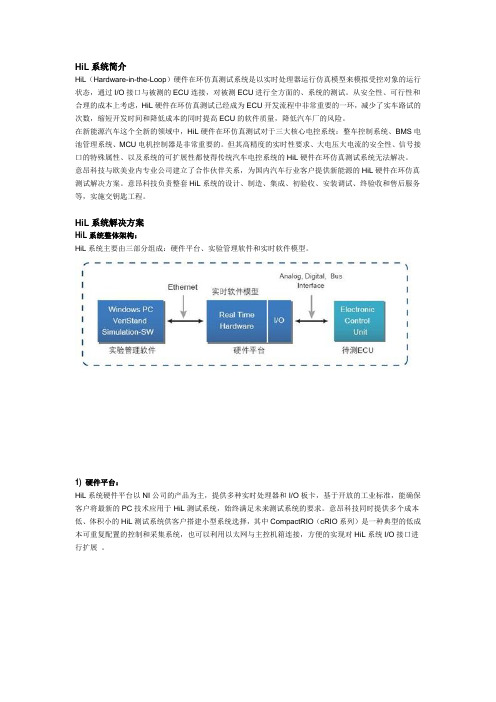
HiL系统解决方案HiL系统整体架构:HiL系统主要由三部分组成:硬件平台、实验管理软件和实时软件模型。
1) 硬件平台:HiL系统硬件平台以NI公司的产品为主,提供多种实时处理器和I/O板卡,基于开放的工业标准,能确保客户将最新的PC技术应用于HiL测试系统,始终满足未来测试系统的要求。
意昂科技同时提供多个成本低、体积小的HiL测试系统供客户搭建小型系统选择,其中CompactRIO(cRIO系列)是一种典型的低成本可重复配置的控制和采集系统,也可以利用以太网与主控机箱连接,方便的实现对HiL系统I/O接口进行扩展。
硬件平台主要组成部分:实时处理器、I/O 接口、故障注入单元(FIU), 通信接口、FPGA模块、负载模拟单元、信号调理单元、可编程电源、机柜和分线箱等。
2) 实验管理软件:HiL系统实验管理软件平台以NI VeriStand 2010 为核心组建,与实时处理器通过以太网连接,配合LabVIEW, FPGA Module,Real Time Module及其他丰富的功能扩展包,用户可进行:硬件配置管理自主更新硬件资源升级系统功能从Simulink等第三方建模环境中导入控制算法或系统模型提供测试命令创建可视化交互界面灵活修改用户界面配置激励生成事件警报完成测试自动化记录数据自动分析数据和生成报告等3) 实时软件模型:HiL系统实时软件模型主要包括:HiL系统采用开放的硬件平台,支持多种仿真模拟软件:发动机模型 Matlab/Simulink/Stateflow/RTW电池模型 LabVIEW Control Design and Simulation电机模型 Tesis enDYNA/veDYNA传动系统模型 CarSim/TruckSim驾驶员模型 GT-POWER车辆动力学模型 AMESim路面及环境模型等HiL系统主要特点:真正开放式的软硬件平台,支持第三方硬件,系统升级与扩展方便支持C, C++, Matlab/Simulink, LabVIEW, DLL等多语言环境实时高精度数据采集和数据多速率采样全球服务、支持与专业的合作伙伴方便集成第三方HiL产品- 电池模拟(DMC)- 电机仿真(OPAL-RT, SET)- 发动机仿真(MicroNova)交钥匙服务。
EMC相关名词缩写
HIL:硬件在环Hardware-In-the-LoopEMC:电磁兼容Electro Magnetic CompatibilityEMI:电磁干扰Electro Magnetic Interference (电磁干扰3要素:电磁骚扰源、骚扰传播途径、敏感设备)EMS: 电磁敏感度(电磁抗扰)Electro Magnetic SusceptibilityEUT: 受试设备Equipment Under TestCAN:控制器局域网络Controller Area NetworkPCB:印刷电路板Printed Circuit BoardISO 11451 整车测试法vehicle test methodsISO 11452 零部件测试法Component test methodsISO 10650 静电放电产生的电气干扰Electrical disturbances from electrostatic dischargeCANoe:总线开发环境CAN open environmentBCM:车身控制模块Body Control ModuleECU:电子控制单元Electronic Control UnitGB:国家强制性标准GB/T:国家非强制性(推荐性)标准ECM:发动机控制模块Engine Control ModuleEPS:电动助力转向系统Electric Power SteeringESC:电子稳定控制Electronic Stability Control,,ESP:电子稳定程序Electronic Stability Program ESP是博世注册专用的,ESC是其他厂家通用的叫法。
LISN:线性阻抗稳定网络(Line Impedance Stabilization Network)。
基于MCD的开放式数控硬件在环虚拟仿真系统开发
Internal Combustion Engine &Parts0引言随着工业4.0数字化工厂以及自动化控制技术的飞速发展,所有企业秉承着时间就是金钱的真理,不断更新生产设备、数据管理系统、控制系统来提高整体的生产效率,降低成本,攻占市场。
以此为目的所开发出的仿真系统也是层出不穷,人们力求在动用最低成本的前提下对之后几个月甚至几年的结果进行预测把控,将生产开发过程中可能遇到的问题与漏洞趁早暴露出来,在设计阶段就将其修复,避免返工,最大限度的降低时间与金钱成本,更多盈利。
研究表明数控系统从生产到投入使用过程中,有70%的生产周期用于控制系统漏洞和错误的修正。
同时,研究表明随着数控系统的复杂程度提高,产品更新换代速度加快,数控系统概念设计阶段实际投入的费用只占产品开发总成本的5%,却决定了产品总成本的70%,其预生产制造,虚拟试运行(Virtual Commissioning ,VC )成为缩短制造成本的关键。
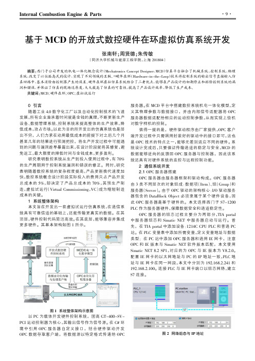
1系统整体架构本文旨在开发出一套虚拟试运行仿真系统,在通信系统具有可靠信道的基础上,还能传输更真实的数据。
在其顶层,硬件控制代码简洁高效。
在其底层,能够兼容并集成更多硬件。
其基本架构如图1所示。
图1系统整体架构示意图以PC 为载体开发硬件控制系统,固高GT-400-SV-PCI 运动控制器为核心,其输出信号作为信号源。
在C#环境中引用OPC 服务器自定义接口,结合硬件驱动开发OPC 数据存取客户端,将数据源以特定格式传递给OPC服务器。
在MCD 平台中搭建数控系统机电一体化模型,定义其物理参数与数据接口,并由内部信号适配器将OPC 服务器数据适配给相应的运动控制参数,从而实现上位机对数字样机的控制。
值得一提的是,硬件驱动程序由厂家提供,OPC 客户端开发过程中只需调用封装好的驱动中的接口即可,这也是OPC 技术的特点之一,能够无差别适应不同的硬件。
系统设计完成后,只要保证传输通道的稳定与安全,MCD 的数据能够逆向的反馈回OPC 服务器与控制器,因此该系统还具有对硬件系统的监控与远程控制功能。
智能集成制动系统的硬件在环测试
现代电子技术Modern Electronics TechniqueDec. 2023Vol. 46 No. 242023年12月15日第46卷第24期0 引 言近年来,随着新能源汽车的普及与发展,比亚迪、蔚来、特斯拉等新能源车企迅速崛起,车辆智能化的提升等相关技术快速发展,作为基础的线控制动技术也得到了迅猛的发展[1]。
智能集成制动系统将助力器和车身电子稳定系统(Electronic Stability Program, ESP )集成为一体,加强了系统的集成化以及轻量化,留出更多的空间用于提升新能源车辆的续航[2]。
随着更多传感器以及电子控制单元(ECU )的介入,制动系统的功能逻辑也逐渐复杂,因此对智能集成制动系统的检测需要比传统模式更先进的检测手段[3‐4]。
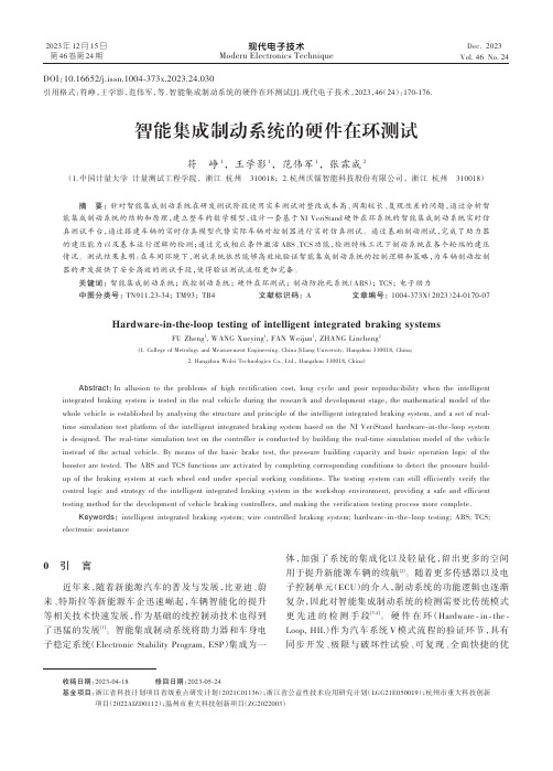
硬件在环(Hardware ‐in ‐the ‐Loop, HIL )作为汽车系统V 模式流程的验证环节,具有同步开发、极限与破坏性试验、可复现、全面快捷的优DOI :10.16652/j.issn.1004‐373x.2023.24.030引用格式:符峥,王学影,范伟军,等.智能集成制动系统的硬件在环测试[J].现代电子技术,2023,46(24):170‐176.智能集成制动系统的硬件在环测试符 峥1, 王学影1, 范伟军1, 张霖成2(1.中国计量大学 计量测试工程学院, 浙江 杭州 310018; 2.杭州沃镭智能科技股份有限公司, 浙江 杭州 310018)摘 要: 针对智能集成制动系统在研发测试阶段使用实车测试时整改成本高、周期较长、复现性差的问题,通过分析智能集成制动系统的结构和原理,建立整车的数学模型,设计一套基于NI VeriStand 硬件在环系统的智能集成制动系统实时仿真测试平台,通过搭建车辆的实时仿真模型代替实际车辆对控制器进行实时仿真测试。
通过基础制动测试,完成了助力器的建压能力以及基本运行逻辑的检测;通过完成相应条件激活ABS 、TCS 功能,检测特殊工况下制动系统在各个轮端的建压情况。
汽车控制器硬件在环的概念
汽车控制器硬件在环的概念英文回答:Hardware-in-the-loop (HIL) testing is a type of testing that involves connecting a physical device to a simulated environment. In the context of automotive controllers, HIL testing is used to test the performance of the controllerin a simulated vehicle environment. This allows engineersto test the controller in a safe and controlled environment, without having to risk damaging the actual vehicle.HIL testing is typically performed using a HIL simulator. A HIL simulator is a computer-based system that creates a virtual environment that simulates the behaviorof the vehicle. The physical controller is then connectedto the HIL simulator, and the controller's performance is monitored and evaluated.HIL testing can be used to test a wide range of controller functions, including engine control,transmission control, and braking control. It can also be used to test the controller's response to different driving conditions, such as acceleration, braking, and cornering.HIL testing is a valuable tool for automotive engineers because it allows them to test the performance of the controller in a safe and controlled environment. This helps to ensure that the controller is functioning properly before it is installed in the actual vehicle.中文回答:汽车控制器硬件在环。
基于硬件在环仿真系统的整车经济性仿真
FRONTIER DISCUSSION | 前沿探讨时代汽车 基于硬件在环仿真系统的整车经济性仿真李特定东风汽车股份有限公司商品研发院 湖北省武汉市 430056摘 要: 硬件在环仿真系统已经成为发动机控制器开发过程中非常重要的工具和平台,对于提高控制器开发效率发挥着重要的作用。
分析某发动机硬件在环仿真台架结构及如何使用仿真台架进行整车发动机经济性仿真计算,并通过实例体现硬件在环仿真系统在汽车整车经济性仿真的应用及相比传统实体台架的优势。
关键词:硬件在环仿真(Hardware in-the-loop simulation)HILs 实时系统 ECU1 硬件在环仿真系统简介汽车发动机控制技术飞速发展,电控单元ECU软件功能日趋复杂,集成度不断提高,传统的测试台架不能在产品制造之前完成对ECU的综合测试,而硬件在环仿真系统可满足此类测试需求,通过在虚拟环境里对被测发动机及车辆进行建模仿真,与ECU组成闭环测试环境,实现ECU的功能测试,无需真实的汽车及发动机,模拟发动机及汽车极限工况测试。
通过Simulink对发动机、传感器、执行器及车辆进行建模,编译成动态链接库(DLL)文件,与实时仿真硬件处理器和仿真信号板卡,组成完整的硬件在环仿真系统。
在构建台架前,需要明确被测对象、测试内容及预期目标。
收集发动机万有特性曲线图、车辆特征参数、传感器特性参数、待测硬件控制器及关键执行器。
2 硬件在环仿真系统设计硬件在环仿真系统设计包含硬件和软件设计,硬件设计包括硬件选型、匹配等,软件设计包括被控对象模型设计及上位机控制界面设计。
2.1 硬件系统设计本文使用NI品牌的硬件,主要包括:PXIe-8135RT实时处理器;I/O板卡(模拟量输入输出,数字量输入输出,PWM输入输出),FPGA板卡(轮速/转速信号模拟、喷油点火信号采集)。
真实硬件主要是各种执行机构:喷油器、高压油泵、节气门、点火线圈、继电器等。
在被测ECU和实时硬件板卡之间增加信号调理和故障注入板卡、负载模拟模块等,整个系统的信号定义及连接端口通过信号列表设计,将ECU真实物理接口和仿真模型之间的IO接口逐个匹配并完成物理连接。
hil 仿真基本原理
hil 仿真基本原理HIL Simulation: Basic PrinciplesHIL simulation, or Hardware-in-the-Loop simulation, is a crucial technique in the development and testing of complex systems, especially in the automotive and aerospace industries.HIL仿真,即硬件在环仿真,是开发和测试复杂系统,特别是在汽车和航空航天工业中的一项关键技术。
At its core, HIL simulation involves the integration of real hardware components with a simulated environment.其核心在于将真实的硬件组件与模拟环境进行集成。
This simulation environment is typically created using specialized software that can replicate the operational conditions and interactions of the system under test.这种模拟环境通常使用专用软件创建,可以复制被测系统的操作条件和交互。
By connecting the hardware components to the simulation, it becomes possible to evaluate their performance and identify potential issues without the need for actual deployment in a real-world setting.通过将硬件组件连接到模拟环境,可以在不需要在真实环境中实际部署的情况下评估其性能并识别潜在问题。
半实物仿真技术
飞行模拟转台的工作原理
基本构成:动力系统、伺服控制系统、机械系统
工作原理:在动力系统支持下,伺服控制系统控制
机械系统作角度转动,为安装在机械系统上的惯性测 量部件提供姿态运动环境。
伺服控制系统:保证转台实现一定性能指标的控制系统:
一般由测速机构成速度内环,提高系统的抗干扰能力, 由测角元件构成位置外环进行位置控制,同时对位置 输入进行微分,实现复合前馈控制,提高系统响应。
半实物仿真技术
半实物仿真概述 物理模拟设备与技术 仿真计算机技术
半实物仿真概述
概念:(Hardware-in-the-loop)
硬件在回路仿真:仿真系统中有实物参加。 优点:可使无法准确建立模型的部件直接进
入仿真回路;通过模型与实物之间的切换, 进一步校验模型;验证实物部件对系统性能 的影响。 实质:为物理部件创造一个模拟实际环境的 仿真环境,用物理部件实物进行仿真的技术。
功能扩展:测试信号、数据记录、曲线显示
飞行模拟转台的组成
动力系统 伺服控制系统 机械系统
动力系统
液压能源
三相电机-油泵 分油器、过滤器、溢
流阀 冷却系统-水箱,水
泵 远程控制系统-调压
阀
动力系统
直流电源
可控硅直流电源 开关稳压电源
伺服控制系统
控制元件:执行控制算法,产生控制信号(电压)
15
10
30~50
200*100*150
0.2
12
备注
0.1-1度双 10
飞行模拟转台功能要求
可使用性:机械电气接口、按钮和指示、视场、零位、初
值与归零、屏蔽与干扰。
可靠性:机械和电气越位开关、操作互锁、手动和自动断电
保护
hil 测试概念
hil 测试概念hil测试概念简介hil测试(Hardware-in-the-Loop Testing)是一种将实际硬件与仿真环境相结合的测试方法,以验证硬件系统的性能和功能是否达到要求。
它能够更真实地模拟实际工作环境下的各种情况,对硬件系统进行全面的测试和评估。
相关概念1.硬件系统(Hardware System): 指待测试的实际硬件系统,可以是电子设备、机械装置等。
2.仿真环境(Simulation Environment): 指模拟硬件系统运行环境的虚拟环境,通常使用计算机软件来实现。
3.模型(Model): 仿真环境中用来描述硬件系统行为的数学模型或逻辑模型,通常使用数学方程或代码来表示。
4.接口(Interface): 用于连接硬件系统与仿真环境的接口,可以是传感器、执行器或其他通信设备。
5.测试用例(Test Case): 描述了对硬件系统进行测试的具体步骤和条件,通常包括输入信号、期望输出等信息。
6.数据记录(Data Logging): 在测试过程中记录硬件系统的输入输出数据,用于后续的分析和评估。
7.实时性(Real-time): hil测试通常要求仿真环境能够以与实际环境相同的速度和时序进行运行,以实现逼真的测试结果。
相关内容在hil测试中,通常包括以下几个步骤:1.系统建模与仿真环境搭建:根据硬件系统的特性和要求,建立相应的数学模型或逻辑模型,并利用仿真软件搭建仿真环境。
2.接口设计与连接:根据硬件系统的接口要求,设计并连接合适的传感器、执行器或通信设备,实现硬件系统与仿真环境的相互作用。
3.测试用例设计与执行:根据测试目标和要求,设计测试用例,并在仿真环境中执行测试,记录硬件系统的输入输出数据。
4.数据分析与评估:对测试过程中的数据进行分析,评估硬件系统的性能和功能是否满足要求,并对可能存在的问题进行排查和修复。
5.结果验证与优化:根据测试结果,对硬件系统进行验证,并根据测试结果进行性能优化或功能改进。
- 1、下载文档前请自行甄别文档内容的完整性,平台不提供额外的编辑、内容补充、找答案等附加服务。
- 2、"仅部分预览"的文档,不可在线预览部分如存在完整性等问题,可反馈申请退款(可完整预览的文档不适用该条件!)。
- 3、如文档侵犯您的权益,请联系客服反馈,我们会尽快为您处理(人工客服工作时间:9:00-18:30)。
Hardware-In-the-Loop (HIL)Hardware-In-the-Loop is a form of real-time simulation. Hardware-In-the-Loop differs from pure real-time simulation by the addition of a “real” component in the loop. This component may be an electronic control unit (ECU for automotive, FADEC for Aerospace) or a real engine. The current industry definition of a Hardware-In-the-Loop system is shown in Figure 1. It shows that the plant is simulated and the ECU is real. The purpose of a Hardware-In-the-Loop system is to provide all of the electrical stimuli needed to fully exercise the ECU. In effect, “fooling” the ECU into thinking that it is indeed connected to a real plant.Figure 1. Hardware-In-the-Loop Definition: Plant is simulated and ECU is real.The benefits of a Hardware-In-the-Loop system as defined above are manifold. This topology was devised to manage the ever-increasing complexity of ECUs. Open loop or “stimulus boxes” were no longer suited to testing ECUs. Why? First off, the ECUswere closing dynamic controls loops to manage, say, fuel mixture. Open loop stimulus-boxes cannot test dynamic closed loops. Second, automated methods were needed to test and verify all the features of the ECU. Hardware-In-the-Loop systems typically have the ability to automatically run through tests automatically. We will talk about this more later.Another benefit of Hardware-In-the-Loop is that testing can be done without damaging equipment or endangering lives. For instance, potentially damaging conditions in an engine, such as over-temperature, can be simulated to test if the ECU can detect and report it. Another instance would be an anti-lock braking (ABS) simulation at performance extremes. If simulated, the performance of the ABS system can be evaluated without risk to the vehicle or operator.If asked to divide the usage scenarios of Hardware-In-the-Loop systems, I would venture that 75% of systems are dedicated to testing the diagnostic code of the ECU. For example, fault simulation and detection. The other 25% of Hardware-In-the-Loop systems are dedicated to development work, i.e. the engineer is developing new ECU features against the simulated plant before taking them to the vehicle. This is somewhat counter-intuitive, but it does reflect the priorities of the Original Equipment Manufacturer (OEM). They need to be in compliance with government regulations such as On-Board Diagnostics (OBD). Fast fault detection can also prevent more serious warranty repair.The typical Hardware-In-the-Loop system is comprised of the following components (see Figure 2):1. A math model of the plant (i.e. engine or vehicle model).2. Sensor models3. A real-time target computer(s) with I/O.4. Real or simulated loads5. Fault insertion relay matrix6. A host PC with communications link to target computer and diagnostic link toECU.7. A Graphical User Interface (GUI) application to download and control the real-time process.8. A test automation application to automate all aspects of the test.Figure 2: Typical Hardware-In-the-Loop system components.As you can see, the Hardware-In-the-Loop system is much more complex than an RCP system. Let’s talk a little about all the components to give you a feel for what the system is.The Model: The plant model is whatever the ECU expects; an engine model, vehicle model, airplane model, etc. The typical question is “where do I get the model, and how good does it have to be?” You can buy off-the-shelf models or make your own. Off-the-shelf models are available for spark and diesel engines, cars, and trucks. They are typically Simulink™ models designed to be run in real-time. You can also design your own plant models or have a specialist do it for you. How good do they have to be? That depends on your application. What I hear a lot is “necessary and sufficient.” In other words the model fidelity must match its intended use. The typical use is for testing the diagnostic capability of the ECU. This would put the least requirements on the model. If you intend to develop ECU control capability against the model, it may need to have higher fidelity. For instance, if you are developing a new multi-injection fueling strategy for your diesel engine, your model should becapable of accumulating and reacting to all of the fuel pulses.Sensor Models: This aspect of the Hardware-In-the-Loop system is often overshadowed by the plant model, but it is nonetheless very important. The sensor outputs from a plant model are perfect – they are, after all, just variables. Unfortunately, real-world sensors are not perfect. Their greatest imperfection is their non-linearity. ECUs compensate for sensor non-linearity, thus, the imperfect sensor response must be modeled. The typical sensor model is realized as a look-up-table since the response it typically fast compared to the time-constants of the plant. If the dynamic response of the sensor is slow it can be modeled dynamically. Some Hardware-In-the-Loop systems will dedicate a entire processor to the sensor models, thus decoupling them from the plant model.Real-time targets and I/O: The majority of Hardware-In-the-Loop systems uses embedded computers to run the models in real-time. The reason for this is to decouple the real-time computing of the Hardware-In-the-Loop system from the host PC. The PC with a MS-Windows® operating system is not real-time. There are some Hardware-In-the-Loop vendors that do use PC hardware for the run-time platform and they accomplish this by running a PC real-time operating system (RTOS) like QNX®. The embedded computers, a.k.a. “targets” communicate with each other and system I/O via a data bus. This bus can be VME, PCI, PXI, or proprietary. They typical physical foot print is a card cage with processor and I/O boards connected with a passive backplane. The I/O boards are typically “instrument grade” in that they are not able to source or sink current. For digital I/O TTL is typical. For analog I/O, operational amplifiers are used.Loads: The I/O provided by the Hardware-In-the-Loop vendor is instrument grade and some signals will need to be amplified and/conditioned to allow connection to the ECU. Loads in an Hardware-In-the-Loop system can be real or simulated. An example of a real load would be a known-good fuel injector. A simulated load would be an Inductive/Resistance (LR) network designed to simulated the frequency response of the injector and be able to sink and dissipate delivered current. The loads and signal conditioning of a Hardware-In-the-Loop system are inherently custom and match the requirements of the ECU under test. Hardware-In-the-Loop vendors anticipate this custom adaptation by designing load and signal conditioning cards that can be easily customized by component selection, i.e. stuffing different inductors, capacitors, or resistors.Fault Insertion: The majority of Hardware-In-the-Loop testing time is used to test the fault detection capability of the ECU. Modern automotive ECUs dedicate half of theirmemory to this task. Key to testing is fault insertion such as wire breaks, shorts to power, shorts to ground, or sensor/actuator failures. Simulating these events is a relay matrix between the Hardware-In-the-Loop and the ECU (see Figure 2). The relay matrix is controlled by the host PC as it steps though manual or automated tests. The link between the relay matrix and the host PC will vary by manufacturer, although some use Controller Area Network (CAN) since it is needed by the Hardware-In-the-Loop system anyway.Host PC: A host PC is used to provide a GUI to the user, to run test automation applications, to control Hardware-In-the-Loop system components such as fault insertion switching, and to provide a diagnostic link to the ECU, to develop/change models and tests, and to collect, store, and report test results. The link between the host and the real-time system is typically Ethernet. Other methods such as proprietary high-speed serial or parallel bus are also used.GUI: The GUI application runs on the host PC. This application allows control of the real time process such as download, start, stop, variable observation, and data collection.Test automation application: This application may be built-in to the GUI or be a separate application that “sits on top” of the GUI. This application provides the user with the ability to automate tests. It accomplished this task by providing the user with a method of authoring a test sequence. The method can be a test script in a language such as Visual Basic® or Python® or it may be symbolic like flowcharts. There is currently no standard language for Hardware-In-the-Loop test automation. Hardware-In-the-Loop systems are complex, expensive, and require a corporate commitment to be successful. Some full-vehicle multi-ECU Hardware-In-the-Loop systems can sell for over a million dollars. The benefits and payback period are not well documented but those that adopt the technology soon find it invaluable for testing and debugging ECUs. The automated test capability makes it possible to run a test-suite on every ECU software change saving countless man-hours over manual methods.Hardware-In-the-Loop is currently THE method for managing ECU software testing.If you are considering Hardware-In-the-Loop we can help you with the process. Please see our vendor selection services or contact us.Home©2005 PrecisionMBA, LLC。