SYSTEM LOGISTICS(西姆斯特物流) 物流设备产品介绍
SYSTEM LOGISTICS(西姆斯特物流) 物流设备产品介绍

3.4、滚筒输送机
滚筒输送机利用按一定间距架设在固定支架上的若干个滚筒来输送成件物品的输送机。
优点: 1、结构简单、运行可靠、维护方便,能够输送单件重量很大的物料。 2、可输送高温物品、节能。 3、可以实现直线、曲线、水平、倾斜运行,能完成分流、合流目的。
缺点: 1、不能直接输送散料、小件物品或不规则的物品。 2、对滚筒的要求高,传动系统比较复杂,建设成本高。
垂直升降定序器 (Vertical Lift Sequencer)
2、存取设备
轻型托盘堆垛机
重型托盘堆垛机
2.1、轻型托盘堆垛机
性能参数 承载重量:低于650kg 作业高度:低于22m 最大运行速度:小于5m/s 优点: 1、作业高度高,运行速度快,作业安全。 2、过道所需宽度窄,空间利用效率高。 3、自动化程度高,作业周转量大。 缺点: 1、承载重量小。 2、设备先进,投资大,系统维护成本高。 3、堆垛机只能直线行走,不能同时在多个巷道作业,运营效率不高。 适于:对塑料箱、纸板箱、托盘等轻货进行存取货作业。
3.3、链式输送机
链式输送机利用链条牵引、承载,或由链条上安装的板条、金属 网带、辊道等承载物料的输送机。 优点: 1、输送能力大、.输送能耗低、使用寿命长。 2、工艺布置灵活,可适应多种地面条件,可水平或爬坡(≤18°)输送。 3、维修费用少。
缺点: 直接用链条牵引时,对货物、托盘的损耗大。 适于:食品、药品、饮料、化妆品、乳业及烟草等的自动输送、分配、 包装的输送。
适于:各类箱、包、托盘等件货的输送,散料、小件物品或不规则的物品需放在托盘上或 周转箱内输送。 滚筒输送机
4、搬运设备
自动无人驾驶车-AGV
货运电梯
4.1、自动无人驾驶车-AGV
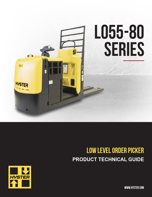
希斯特低级货物拣选机产品手册说明书
Height/standard battery rollers
20 Floor to top of battery rollers Side extraction
21 Travel speed - NL/RL
22 Lift speed - NL/RL
Forks
Cab
23 Lower speed - NL/RL
32.0 (814.0)
Battery dimensions
“X”
“Y”
“Z”
in (mm)
26.1 (663)
12.8 (325)
23.3 (592)
30.9 (785)
13.0 (330)
23.3 (592)
30.9 (785)
13.0 (330)
30.8 (782)
Battery connector: 175 Amp. red Battery lead: length 20” (508 mm), position “B”, 1/0 AWG
Vulkollan/polyurethane
10 x 3.5/10 x 3.5 (254 x 90/254/90)
10 x 3.5/10 x 3.5 (254 x 90/254/90)
1x/4 Lead acid | Thin Plate Pure Lead* | Lithium-ion*
3.5 (2.6)
Number of cells
Cell size
Plates per cell
Capacity 6 hour rate
amp hr (kwh)
12
85
11
425 (9.9)
12
85
13
M-System MD7ST 产品说明书

BEFORE USE ....Thank you for choosing M-System. Before use, please check contents of the package you received as outlined below .I f you have any problems or questions with the product, please contact M-System’s Sales Office or representatives. ■PACKAGE INCLUDES:Surge protector ....................................................................(1) ■MODEL NO.Confirm Model No. marking on the product to be exactly what you ordered.■INSTRUCTION MANUALThis manual describes necessary points of caution when you use this product, including installation, connection and basic maintenance procedures.When using this product in potentially explosive atmos-phere or hazardous (classified) location, you have to follow the safety procedure to install it. Please refer to “SAFE IN-STALLATION MANUAL” for each type of certification.LIMITATION APPLICABLE TO M-RESTERThe M-RESTER will protect electronics equipment from damage caused by lightning by absorbing most of the surge voltages.However, M-RESTER may not be effective against cer-tain extremely high voltages caused by a direct or almost direct hit by lightning.M-RESTER must be installed according to this installa-tion / instruction manual.GENERAL■FUNCTION & FEATURES• High discharge current capacity 20 kA (8 / 20 µs), 1 kA (10 / 350 µs)• Ultra-thin 7-mm-wide module can be mounted in high density• Excellent protection employing multi-stage SPD circuits • DIN rail mounting and grounding • Shield terminal provided ■SPECIFICATIONS See Table 1.Table 1. SpecificationsMODEL NO.NOMINAL VOLTAGE MD7ST -24MD7ST -60SHLD TERMINAL FF FG GF GG FF FG GF GGMax. continuousoperating voltage (Uc)Line to Line 30V 70VLine to Earth ±160V 30V ±160V 70V Line to SHLD±160V 30V ±160V 70V SHLD to Earth±160V short ±160V short ±160V short ±160V shortVoltage protection level (Up)@4kV (1.2 / 50 µs)Line to Line 60V 115VLine to Earth ±800V ±60V ±800V ±115VLine to SHLD±1200V ±800V ±60V ±1200V ±800V ±115V SHLD to Earth±800V short ±800V short ±800V short ±800V shortLeakage current @Uc Line to Line ≤5µA ≤5µA Other sections ≤5µA ≤5µA Response time Line to Line≤4 nsec.≤4 nsec.Other sections≤20 nsec.≤20 nsec.Max. discharge current (Imax)20kA (8 / 20 µs), 1.0kA (10 / 350 µs)Nominal current (I N )250mAInternal series resistance Without fuse 4.7Ω ±10% per line 10Ω ±10% per line With fuse 7.5Ω ±10% per line 12.5Ω ±10% per line056 222 38 18SEN TRONIC AGPOINTS OF CAUTION■ENVIRONMENT• Indoor use.• When heavy dust or metal particles are present in the air, install the unit inside proper housing with sufficient ventilation.• Do not install the unit where it is subjected to continuous vibration. Do not subject the unit to physical impact.• Environmental temperature must be within -25 to +85°C (-13 to +185°F) with relative humidity within 30 to 90% RH in order to ensure adequate life span and operation.• This unit needs a DIN rail as earth grounding bar. Ox-ide coating of an aluminium rail may lower the electric conductivity between this module and the ground. Use a steel or copper rail.■DIELECTRIC STRENGTH TESTING• The surge protector starts discharging when 160V or greater voltage (with floating shield type) or several volts (with grounding shield type) is applied between lines and earth. Remove the grounding wire before conducting a test. Be sure to return the wire after the test.■AND ....• We recommend that you keep spare surge protectors so that you can replace them when necessary.• Lightning surge can enter not only through signal lines but also through power supply lines. We recommend that you also use the Lightning Surge Protector for Power Lines for adequate protection. COMPONENT IDENTIFICATION*Option identified by model number suffix.INSTALLATIONMount the unit on a DIN rail. Once installed, do not move it to another DIN rail.■MOUNTING THE UNIT ON A DIN RAILA) Hang the upper hook of the DIN rail mounting adaptor at the rear side of unit, on the DIN rail.B) Push in the lower in keeping pressing the unit to the DIN rail.C) DIN rails generally have slight individual variability in size. If you find it difficult to push in the lower part, go back to (A) and hang the upper part more deeply onto the rail and try (B) again.■REMOVING THE UNITA) Push down the spring loader utilizing a minus screwdriv-er.B) Confirm that it is pulled enough down and pull out the lower part of the unit.C) Detach the upper part from the DIN rail.REPLACING FUSE1)Hang the tip of a minus screwdriver on the groove at ei-ther side of the fuse and push it out of the housing.2)I nsert a replacement fuse. There is no polarity for thefuse to be observed.TERMINAL CONNECTIONConnect the unit as in the diagram below .Be sure to ground the DIN rail on which the unit is mounted and cross-wire between the rail and FG terminal of the protected device as shown in Figure 1 in order to equalize the earth potential.When the unit is connected with a device which has no FG terminal, ground the surge protector only . ■EXTERNAL DIMENSIONS unit: mm (inch)8–M3 EURO■Figure 1. GROUNDINGCross-wire from the DIN rail to the metal housing of the protected device to equalize the ground potential.Ground only the surge protector when the protected device has no grounding terminal.■CAUTION WHEN WIRINGHold the module steady at the front when you tighten/loosen screw terminals.■CONNECTION DIAGRAM• Specify ‘Loop disconnect fuse’ type when multiple transmitters are connected to single power bus.• Loop disconnect fuse is used to separate a transmitter loop from the power bus when it fails in the shortcircuit mode.4 – 20mA Field-mount*1. O xide film on the surface of an aluminium rail may lower the electric conductivity between this module and the ground.Use a steel or copper rail.*2. B e sure to ground the DIN rail. Recommended grounding resistance ≤100Ω*3. C ross-wire between the DIN rail and the metal housing of the protected device to equalize the earth potential. Ground only the surge protector when the protected device has no ground terminal.*4. S hield wiring method is an example. Proceed according to the system requirements.WIRING INSTRUCTIONS■EURO TERMINALTorque: 0.3 N·mApplicable wire size: 0.2 – 2.5 mm2Stripped length: 8 mmMAINTENANCECheck surge protectors periodically. Many cases of light-ning are ignored, and even lightning at a far distance often causes inductive surges.We recommend that you check your surge protector about twice a year, before and after the rainy season. Check whenever you experience a strong lightning occurrence. Checking procedure is explained in the following:■CHECKINGWIRING1)Make sure that wiring is done as instructed in the con-nection diagram.2)Make sure that the DI N rail is connected to the metal enclosure of protected device.3)Make sure that the surge protector is securely attached to the DIN rail, and that the rail is grounded to earth.■DISCHARGE ELEMENT1)Remove all wiring connected to the surge protector when you test the module.2)Check resistance across the terminals indicated in Table 2 on the high resistance range of multimeter and confirm no conduction. The tester should show 10 MΩ or greater.3)Confirm conduction across the same terminals with a 500 V DC 1000 MΩ insulation tester. The tester should show 20 MΩ or less.With loop disconnect fuse option, confirm conduction across the following terminals on the high resistance range of multimeter. The tester should show 15 Ω or less.1 – 4,2 – 5Polarity of the insulation tester does not matter.4)I f any of the above tests shows negative, replace the surge protector.Table 2.TERM.MODEL MD7ST-xFF MD7ST-xFG MD7ST-xGF MD7ST-xGG4 – 5Yes Yes Yes Yes4 – 8No Yes Yes Yes5 – 8No Yes Yes Yes8 – 5No No Yes Yes5 – DIN rail Yes Yes No Yes8 – DIN rail Yes No Yes No Note 1: A pply (+) voltage of the multimeter to the terminal number indicated on the left side.Note 2: Polarity does not matter for the insulation tester.。
Site Master产品说明书

Site Master is a precision analysis tool which measures SWR, Return Loss and Distance-T o-Fault (DTF) on both analog and digital transmission lines.Site Master’s DTF and Return Loss (SWR) measurements are accurate and repeatable, even in the presence of RF interference.Thus,small degradations to RF performance can be spotted before more serious damage occurs.For example, loose connectors and moisture intrusion can be detected before corrosion destroys the cable −saving thousands of dollars in material and re-installation costs.Since sixty to eighty percent of a typical cell site’s problems are caused by problematic cables, connectors and antennas, Site Master pays for itself quickly.Site Master isolates transmission faults using Frequency Domain Reflectometry (FDR).FDR technology is different from traditional TDR (Time Domain Reflectometry)techniques.The FDR technique uses RF frequencies instead of TDR type DC pulses.Thus, FDR can locate RF faults, not just DC open or short circuit conditions.FDR also accounts for cable attenuation versus distance,the display accurately indicates the return loss of the antennas −allowing technicians to perform fault isolation from ground level.Internal memory provides an efficient means of storing measurement data for future analysis.Site Master includes advanced software tools for archiving data.Limit lines provide a quick visual and audible pass/fail indication.Site Master’s rugged construction and wide temperature range provide trouble-free operation in the field.Powerful Software Tools Return Loss or SWR data is down loaded to PC via RS-232.Site Master Software Tools calculate Distance-T o-Fault (Return Loss versus Distance) and Smith Chart.During the Site Commissioning process, the antenna system’s Return Loss (SWR) and Distance-To-Fault “Signature”characteristics are down-loaded to a PC database.Maintenance technicians recall the “Signature”characteristics for comparison tosubsequent monthly/quarterly maintenance verification.The Windows based “drag-and-drop”capabilityspeeds fault identification.Site Master™n Distance-To-Fault Measurementsn Accurately Tests RF Transmission Lines and Antennas n Precision SWR and Return Lossn Immunity to Live Site RF Interference n Synthesizer Accurate to 75 ppmnInternal Memory Saves Up to 40 Traces and 9 Setups Software Toolsn Smith Chart and Distance-To-FaultnCompare Measurements to Historical DataUse the Smith Chart for impedance matching of antennas and trans-mission line quality checks.Historical performance changes can be eval-uated by overlaying stored data traces on a personal computer.0−40−60−200 - 5 metersDistance To Fault−801981Immunity to RF Interference Site Master’s design is highly resistant to interference from incoming and ambient signals.RF suppression capabilities are realized with fre-quency-selective, narrowband receiver technology and a proprietary phase tracking synthesizer technique.RF modulation is transparent to the Site Master making it useful in any cellular modulation environment.Distance-To-Fault displays represent Return Loss or VSWR information.Measurement AccuracyMeasurement accuracy depends on the quality of the coaxial calibration components.The charts below show the Measured Value (dB) vs.Uncertainty for standard and precision calibration components.Ordering InformationModel S331 (25-3300 MHz), Built-in DTF Model S111 (300-1200 MHz), Built-in DTF Model S330 (700-3300 MHz)Model S110 (600-1200 MHz)Standard Accessories Included:• Operating Manual • Soft Carrying Case• Standard Calibration Components • AC-DC Adapter• Automotive Cigarette Lighter/12 Volt DC Adapter• One Y ear Warranty (includes battery, Firmware and Software)• 3.5 inch Floppy Disk containing Fault Location (DTF), Smith Chart and Software Management T ools • Serial Interface CableOptional Accessories/Spares:Precision N T ype Short-Open:PN 22N50Precision N T ype Load, 42 dB:PN SM/PL Test Port Cable, Armored, 1.5 meter:PN TP/EC 1.5Test Port Cable, Armored, 3.0 meter:PN TP/EC 3.0Test Port Cable, Armored, 5.0 meter:PN TP/EC 5.0Test Port Cable, Non-Armored, 1.5 meters PN TP/ECN 1.5Test Port Cable, Non-Armored, 3.0 meters PN TP/ECN 3.0Test Port Cable, Non-Armored, 5.0 meters PN TP/ECN 5.0Spare Standard N T ype Short:PN SM/STS Spare Standard N T ype Load, 35 dB:PN SM/STL Spare Soft Carrying Case:PN D41955Spare AC-DC Adapter:PN 40-74Spare Automotive 12 Volt Adapter:PN 806-62Spare Serial Interface Cable:PN 800-441Transit Case for Site Master:PN 760-194N male to 7/16 female Adapter PN 510-90N female to 7/16 female Adapter PN 510-91N male to 7/16 male Adapter PN 510-92N female to 7/16 male Adapter PN 510-9376432150 - 30 meters Distance To Fault 0VSWR 00−10−30−40−50−60−200 - 30 meters Distance To FaultRL Measured Value (dB)U n c e r t a i n t y (d B )51015202586420UNCERTAINTY CHART MODEL S110, S111Measured Value (dB)U n c e r t a i n t y (d B)51015202586420UNCERTAINTY CHART MODEL S330, S331TowerAntenna, directionalAntenna, omnidirectionalCoaxial cableCoaxial cableGrounding kitEquipment end connectorWall/roof feedthroughAngle adapter kitGrounding kitHanger mountHoisting gripCeiling adapterLow VSWR jumperLightning arresterCable hangerSite Master easily locatesfaults anywhere on the transmission lineFactory UpgradesSite Master S110 to S111ND42502Site Master S330 to S331ND42504Site Master S110 to S330ND42505Site MasterS111 to S331ND42506SpecificationsSite Master Technical Specifications*:* Specifications apply when calibrated at ambient temperature.** Fault location is done by Inverse Fourier Transformation of data taken with the Site Master.Resolution and Max Range depend on the number of frequency data points, frequency sweep range and dielectric constant of the cable being tested:Resolution (meters) = 1.5 x 10⁸/(∆Frequency √εϒ)Maximum Range = Resolution x 128*** The Immunity Uncertainty Curves represent a typical application of a worst-case scenario:Measurements were made in CW mode by injecting a signal into the Site Master through a coupler with the same signal injected through the coupled arm.In real life applications, signals are not CW but modulated and varying in frequency.Immunity is typically better when swept frequencies are used.U.S.Sales Centers:North West (408) 776-8305North East (201) 227-8999Central (214) 644-1777South West (310) 715-8262South East (301) 590-0300International Sales Centers:Europe Intl.44 (1582) 418853Japan (03) 3446-1111Canada (613) 828-4090Asia-Pacific Intl.81 (3) 3440-2770Microwave Measurements Division •490 Jarvis Drive •Morgan Hill, CA 95037-2809FAX (408) 778-0239Printed in USA11410-00173November 1995;Rev:ADS Site Master-2 /GIP-GData subject to change without noticeFor more information or a demonstrationcall the Site Master Technical Hot Line at (201) 227-8999.。
DEMATIC物流设备产品介绍(PPT 34页)

适于:储存高生产量纸箱和货柜。
2.3、Multishuttle™货架
Multishuttle™货架是与多层穿梭车配套设计的货架,用于支撑穿梭车 在各层的相邻货架的边缘上通行、存取货作业。
优点: 1、可提供单个托盘深度与两个托盘深度的存储。 2、通过多层穿梭车的配合,能对多种货物进行存储、输送。 3、设备自动化程度高,可实现无人操作。
缺点: 1、将仓库划分为几个区域,有些区域货架的存储效率并不高 2、单位面积承载货物很重,对地面的承受能力要求很高。 3、制作货架需要大量的成本投入,在作业量不大的情况下是不划算的
2.1、高层货架
优点: 1、货架可以拆卸调整。高度可达30m,大大提高了仓库单位面积的仓储能力。 2、配备装卸搬运机械,升降机可通过多条巷道上下左右连续作业,物资运输快。 3、物资的存取作业由计算机控制,可以及时查对库存,根据库存多少,安排进货计划,避免 积压。 缺点: 1、对地面单位面积的载重能力要求高。 2、需要配套的堆垛机,建设、维修成本高。 适于:存储量较大的仓库、配送中心使用。
优点: 1、节省劳动力,节约占地。 2、出入库作业迅速、准确、缩短了作业时间。 采用了先进的控制手段和作业机械,采用最快的速度,最短的距离送取货物,使商品出入库的 时间大大的缩短。 3、提高仓库的管理水平 由于电子计算机控制的自动化仓库结束了普通繁杂的台帐手工管理办法,使仓库的帐目管理 以及大量资料数据通过计算机贮存,随时需要,随时调出,既准确无误,又便于情报分析。 4、有利于商品的保管。 在自动化仓库中,存放的商品多、数量大,品种多样。由于采用货架--托盘系统,商品在托盘 或货箱中,使搬运作业安全可靠,避免了商品包装破损、散包等现象。
希斯特3轮电动搬运车产品介绍说明书
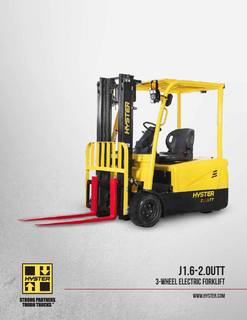
J1.6-2.0UTT 3-WHEEL ELECTRIC FORKLIFT2OVERVIEWThe cost-effective Hyster UT series is a suitable option for less demanding applications, backed by the power of the Hyster name.THE RANGEThe J1.6-2.0UTT range is available in three different capacities:1,600KG – J1.6UTT 1,800KG – J1.8UTT 2,000KG – J2.0UTTDESIGNThe design of the UT range has been engineered with the driver in mind. The ergonomically designed operator compartment, with a wide range ofstandard features and options, can be configured to the needs of the operator and the application.1HIGH STRENGTH OVERHEAD GUARDThe profiled steel overhead guard features high strength materials to enhance reliability and operator protection.2AC CONTROLLERControllers optimize battery powerconsumption. AC traction and hydraulic motors improve precision. All are easily accessible to minimize service time.3WIDE AND LOW STEPThe conveniently positioned non-slip step coupled with large grab handles provide easy and secure access to the truck.4WIDE VIEW MASTThe wide view mast delivers excellent visibility of the load and operator’s forward field of view, optimizing comfort and productivity .5SMALL, ADJUSTABLE STEERING WHEELThe small diameter steering wheel requires low effort, promoting light and precise operation. The adjustable steer column optimizes comfort and convenience.6DUAL DRIVE MOTORSThe compact structure of the drive system provides adequate access for maintenance. Precision cut gears are incorporated, leading to reduced wear and lower noise levels.FEATURES24 53163LOW COST OF OWNERSHIPThe use of high quality and robust components within the UT series deliver a reliable operation with limited wear and tear. Maintenance costs and requirements are further reduced by simple, readily available, genuine and cost effective replacement parts. HYDRAULICSHigh quality cylinders with hard chrome rods reduce seal wear for long life. A full-flow, low pressure filter on the return line keeps the hydraulic oil clean, which helps to minimize seal and pump wear. In addition, this keeps the control valve in good condition, leading to low service costs.4ENGINEERED FOR DRIVERSSAFETY AND COMPLIANCE• H igh visibility, shock absorbing mast enables soft landing• C ontrollable mast lowering speed helps to avoid damage• Secure overhead guard • Standard LED lights • O perator presence systemCOMFORT• H ydraulic power steering requires low steeringeffort for precise positioning • D river fatigue minimized by full suspension, superior comfort and lumbar support seat • A djustable steering column and seat to suit all operators• Low noise and vibration • L ow entrance step, large uncluttered floor space and ergonomically positioned pedals • E rgonomic handbrake and operator controlsPERFORMANCE• O n-demand hydraulic power steering, withtwin drive motor system, delivers superb maneuverability and low energy consumption • E xcellent stopping capability – deliveredthrough maintenance free oil-immersed brakes and regenerative braking system • S imple and clear dash display • D isplay with integrated performance selection functions • A C traction and lifting motors, with electronic control, helps improve performance • S equential seatbelt interlockSERVICE• A C traction and hydraulic motors help reducemaintenance costs • E asy service access to the controllers – mounted inside the counterweight, at waist height, protected by removable cover • I P54 Design – protects the hydraulic and drive motor components • R eadily accessible drivetrain – minimizing service time • C ANbus communication simplifies troubleshooting5Mast typeMax fork height (mm)Overall extended heightFree liftMast tilt Capacity without side shift Lowered height (mm)Lift heightWithout LBR(mm)With LBR (mm)Forward (Deg)Back (Deg)@ 500mm Single pneumatic tire (kg)@ 600mm Single pneumatictire (kg)Without LBR (mm)With LBR (mm)1.6T 1.6T 1.6T1.6T 1.6T 2LFL300019753490401035356616001435330021253790431035356616001435350022253990451035356616001435370023254190471035356616001435400025254490501035353516001435450027754990551035353514001255500030255490601035353512501120550033255990651035353511501030600035756490701035353510509402FFL3000197534904010151099066160014353300212537904310166011406616001435350022253990451017601240661600143537002325419047101860134066160013304000252544905010206015403516001330 3FFL400018504490501013858653516001330435019754840536015109903515001345450020254990551015601040351400125548002125529058101660114035130011655000222554906010176012403512501120550023905990651019251405351150103060002575649070102110159035105094065002790699075102325180535900805J1.6UTT MAST AND CAPACITY TABLENote: For integral sideshift deduct 50kg from stated capacityMAST SPECIFICATIONSMast typeMax fork height (mm)Overall extended heightFree liftMast tilt Capacity without side shift Lowered height (mm)Lift heightWithout LBR(mm)WithLBR (mm)Forward (Deg)Back (Deg)@ 500mm Single pneumatic tire (kg)@ 600mm Single pneumatictire (kg)Without LBR (mm)With LBR (mm)1.8T 1.8T 1.8T 1.8T 1.8T 2LFL300019753490401035356618001615330021253790431035356618001615350022253990451035356618001615370023254190471035356618001615400025254490501035353518001615450027754990551035353516001435500030255490601035353514501300550033255990651035353512001075600035756490701035353511009852FFL3000197534904010151099066180016153300212537904310166011406618001615350022253990451017601240661800161537002325419047101860134066180015004000252544905010206015403518001500 3FFL400018504490501013858653518001500435019754840536015109903517001525450020254990551015601040351600143548002125529058101660114035150013455000222554906010176012403514501300550023905990651019251405351200107560002575649070102110159035110098565002790699075102325180535950850J2.0UTT MAST AND CAPACITY TABLEMast typeMax forkheight (mm)Overall extended heightFree liftMast tilt Capacity without side shift Lowered height (mm)Lift heightWithout LBR (mm)With LBR (mm)Forward (Deg)Back (Deg)@ 500mm Single pneumatic tire (kg)@ 600mm Single pneumatictire (kg)Without LBR (mm)With LBR (mm)2.0T 2.0T 2.0T 2.0T 2.0T 2LFL3000197534904010545466200017953300212537904310545466200017953500222539904510545466200017953700232541904710545466200017954000252544905010545435200017954500277549905510545435180016155000302554906010545435150013455500332559906510545435130011656000357564907010545435120010752FFL3000197534904010151099066200017953300212537904310166011406620001795350022253990451017601240662000179537002325419047101860134066200016654000252544905010206015403520001665 3FFL400018504490501013858653520001665435019754840536015109903519001705450020254990551015601040351800161548002125529058101660114035165014805000222554906010176012403515001345550023905990651019251405351300116560002575649070102110159035120010756500279069907510232518053510008956SPECIFICATIONSD i s t i n g u i s h i n g m a r k 1.1Manufacturer MeasurementHyster Hyster Hyster 1.2Model designationJ1.6UTT J1.8UTT J2.0UTT 1.3Power: battery, diesel, LPG, electric mainsBattery Battery Battery 1.4Operation: manual, pedestrian, stand, seat, orderpicker Seated Seated Seated 1.5Load capacity Q (kg)1600180020001.6Load center c (mm)5005005001.8Load distance x (mm)3713713711.9WheelbaseY (mm)140014001515W e i g h t 2.1Unladen weight (max. battery)kg 3120319033802.2Axle loading, laden front / rear (max. battery)kg 4010 / 6604420 / 5104870 / 5802.3Axle loading, unladen front / rear (max. battery)kg 1480 / 16401500 / 16901580 / 1810T i r e s , c h a s s i s 3.1Tires: L=pneumatic, V=cushion, SE= superelastic SE SE SE 3.2Tire size, front 18 × 7-818 × 7-8200 / 50-103.3Tire size, rear15 × 4.5-815 × 4.5-815 × 4.5-83.5Number of wheels, front / rear (X = driven) 2x / 22x / 22x / 23.6Track width, front b10 (mm)9339339523.7Track width, rear(mm)186186186D i m e n s i o n s 4.1Mast tilt, forward α / back β degrees 6/66/66/64.2Height of mast, lowered h1 (mm)1992199219904.4Lift height “h3 (mm)3036303630454.5Height of mast, extended E h4 (mm)4030403040004.7Height to top of overhead guard m h6 (mm)2002200220044.8Seat height u h7 (mm)9659659654.12Towing coupling height h10 (mm)4454454854.19Overall length (with forks)l1 (mm)2894289431534.20Length to face of forks l2 (mm)1974197420844.21Overall width b1 (mm)1084108411404.22Fork dimensionss /e / l (mm)35 / 100 / 92035 / 100 / 92040 / 120 / 10704.23Fork carriage DIN 15173. class, A / B 2A 2A 2A 4.24Fork carriage width E b3 (mm)9509509504.25Width over forksb5 (mm)8908908904.31Ground clearance, laden, below mast m1 (mm)9090904.32Ground clearance at centre of wheelbasem2 (mm)9696964.33Aisle width with pallets 1000 mm long × 1200 mm wide Ast (mm)3290329034454.34Aisle width with pallets 800 mm wide × 1200 mm long Ast (mm)3415341534104.35Outer turning radius Wa (mm)1601160117164.36Inner turning radius b13 (mm)000P e r f o r m a n c e d a t a 5.1Travel speed laden / unladen km / h 14 / 1614 / 1614 / 165.2Lifting speed laden / unladen mm / s 352 / 500349 / 500310 / 5005.3Lowering speed laden / unladenmm / s 344 / 420382 / 421390 / 4305.6Maximum drawbar pull laden / unladen, 5 minute rating N 15500 / 1000015000 / 1050015500 / 120005.8Maximum gradeability with / without load, 5 minute rating %20 / 3020 / 3020 / 305.9Acceleration time with / without load 10m sec 4.4 / 4.3 4.4 / 4.3 5.9 / 5.65.10Service brakeHydraulic Hydraulic Hydraulic E l e c t r i c -m o t o r 6.1Drive motor rating, S2, 60min kW 2 × 5.0 2 × 5.0 2 × 5.06.2Lifting motor, S3 15% rating kW 1111116.3Battery DIN 43531 / 35 / 36 A, B, C, no 43531A 43531A 43531A 6.4Battery voltage / capacity (5hr rate)V/Ah 48 / 46048 / 46048 / 6006.5Battery weight (min / max)kg 9459451090Battery dimensionsl / w / h (mm)830 / 630 / 627830 / 630 / 627830 / 738 / 6276.6Power consumption in accordance with VDI cycle kWh / h 5.19 5.3 5.7A d d i t i o n a l d a t a8.1Drive control AC AC AC ManufacturerZAPI ZAPI ZAPI 8.2Operating pressure for attachments x bar 1451751758.3Oil volume for attachments Vmin 3838388.4Average noise level at operator's ear ¬dB (A)64.864.869.68.5Towing coupling, type DINØ32Ø32Ø32¬ L PAZ, measured according to the test cycles and based on the weighting values contained in EN12053“ Bottom of forksu Full suspension specified E Without load backrestm h6 subject to +/- 5 mm tolerance x VariableSpecification data is based on VDI 2198, with the following configuration: Complete truck with 3000mm 2-stage limited free lift mast, standard carriage and forks, overhead guard and standard superelastic drive and steer tires.7DIMENSIONSAst = Wa + x + l6 + aa = Minimum operating clearance of 200mm l6= load length7382X 152X 158306275805601802306302X 152X 15750680980ModelCompartment sizeBattery specifications Electrical Battery sizeWeightW mm (in)L mm (in)H mm (in)Voltage W mm (in)L mm (in)H mm (in)Min kg (lbs)Max kg (lbs)J1.6-1.8UTT Vertical extract 843 (33.1)634 (24.9)645 (25.3)48830 (32.6)630 (24.8)627 (24.6)898 (1980)992 (2185)J2.0UTT Vertical extract843 (33.1)752 (29.6)645 (25.3)48830 (32.6)738 (29.0)627 (24.6)1034 (1980)1142 (2515)Battery type: “EO” (without cover)Battery compartment length is measured front to rear. Battery compartment width is measured across the truck Battery lead: length 250mm (10”), bosition “B”, 2 / 0 AWGBATTERY COMPARTMENT SPECIFICATIONSJ1.6-1.8UTTJ2.0UTTHyster Company P .O. Box 7006Greenville, North Carolina 27835-7006Part No. J1.6-2.0UTT/BTG 3/2021 Litho in U.S.A.Visit us online at or call us at 1-800-HYSTER-1.Hyster, and STRONG PARTNERS, TOUGH TRUCKS, are registered trademarks in the United States and certain other jurisdictions. Hyster products are subject to change without notice.Trucks may be shown with optional equipment. © 2021 Hyster Company. All rights reserved.。
Stryker EMS产品说明书
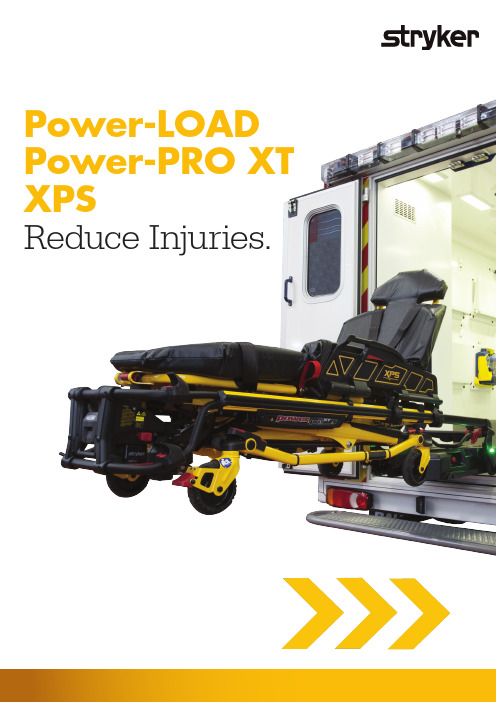
Power-LOAD Power-PRO XT XPSReduce Injuries.Reduce injuries.We at Stryker work in partnership with EMS personnel to understand the environmentin which EMS products operate and the demands that are placed on them. Teams ofengineers then focus on developing robust and reliable equipment that help make the paramedic’s job easier, safer and more efficient. Stryker EMS products are built to lastand strong enough to handle the rigorous demands of the EMS environment.23At Stryker, we put quality first in everything we do. We continually improve our quality systems to develop, produce and market products that meet or exceed the requirements of customers and regulatory agencies around the world.Safety it’s a powerful thing.SMRT – Efficient Power-PRO XT battery managementSMRT batteries with inductive charging - The SMRT Power System will give your Power-PRO cot performance. This is a tough, professional-grade system designed for the high-pressure world of EMS. The SMRT Power System eliminates the time-consuming and elaborate charging protocols and “tuning” usually required formaintaining reliable, high performance battery-powered systems. In combination with Power-LOAD it is charged while you are driving with inductive charging. This ensures a reliable operation of the system.Safety features( P ower-LOAD and Power-PRO XT)• A ngle sensors – within the system indicate the Power-LOAD lifting arms are at the correct position to release thecot from the trolley.• S upport sensors – ensure that the wheels of the cot are on the ground before the lifting arms stop supporting the cot.• S afe position feature – the Power-LOAD lifting arms will not lift if the cot is not in position and ready to be loaded.• S afe cot release – if the lifting arms have not lowered, the cot release handles will not function.• M anual override – for cot release handles on the head-end of the trolley on both the patient right and patient left that will allow manual release of the trolley head-end.• M anual back-up – lowering of lifting arms in any circumstance by pressing and holding manual lower button.• T ransfer lock override – transfer can be manually pushed into the ambulance and can be secured for transport and vice versa.• Power-LOAD battery – non-spillable battery for durability.• W ireless communication safety feature – if two cots are within the same vicinity or within the same ambulance they will not cross communicate.• S afety hook – assures handling confidence when loading and unloading in the event of power loss.• P ressure-locking valve – Power-PRO has been designed with a pressure-locking valve that prevents the cot from lowering when the manual release handle is pulled, until the pressure is released from the head and foot-end of the cot. - T his same feature exists when loading with Power-LOAD, the foot-end operator can hold the manual release valve, raise the cot legs, and push the cot into transport position.- W hen unloading, the foot-end operator can squeeze the manual release handle to lower the legs, and the cot will not lower completely until the manual override panel is used to lower the Power-LOAD lifting arms.U L recognised to UL 60601-1 (Medical Electrical Equipment, Part 1: General Requirements for Safety)C ompliant to IEC 60601-1-2 (Electromagnetic Compatibility)T ransmitter: FCC, IC, and ACMA approved, RTTE compliantB S EN 1789 European standard governing the performance and safety of road ambulances, a requirement of which is the dynamic evaluation of the cot fastener as a system to 10g in theforward, rearward, left, right and vertical directions (using a 50th percentile manikin).I PX6 refers to the product’s ability to withstand powerful jets of water without adverse effects.C E: MDD, RTTE Directive Certifications / testingsPower-Pro XTPowered ambulance cotcapacity318kgReduce the risk of injuries when raising and lowering.Medics experience frequent spinal loading due to repetitive motions such as lifting, lowering, carrying, and bending. Use of the Power-PRO XT has proven to reduce spinal loading, resulting in reduced injuries, lost or modified workdays and workers’ compensation costs, and intends to increase recruitment and retention.1Lift-capable safety barAssures handling confidence. Reduces lift height for smaller operators.Oversised wheelsRequires less force to roll, improving manoeuvrability over rough terrain.Retractable head sectionThe retractable head section with safety bar has conveniently located release handles that retract the head section into the cot. The safety bar release is designed to keep hands away from the cot mechanism.Battery pack release controlAccessible and easily changed.Head and foot-end lift and grip sectionErgonomic lifting handles optimised to 30 degrees. Grips have a textured, durable, nonslip surface for operator control.US patented x-frameWill not hot drop.Key features and benefits Power-PRO XT 6506:• Hydraulic lift system• Settable load height with jog function • Power-LOAD compatibility option• Shock, flat leg or optional knee gatch positioning• Retractable head section41. Evaluation of Medical Cot Design Considering the Biomechanical Impact on Emergency Response Personnel – T.K. Fredericks, S.E. Butt, K.S. Harms, J.D. Burns XXVth Annual Occupational Ergonomics and Safety. Conference.Power-LOADPower-loading cot fastener systemLifts and lowers the cot into and out of the ambulance, reducing spinal loads and the risk of cumulative trauma injuries.The Power-LOAD cot fastener system is designed to improve operator and patient safety by supporting the cot throughout the loading and unloading process. The reduction in spinal load helps prevent cumulative trauma injuries. Power-LOAD wirelessly communicates with Power-PRO cots for ease of operation and operator convenience.1Key features and benefits• Lifting arms• Head end LED indicators • Cot release handles• Linear transfer system • Duplicate LED indicator • Manual trolley release • Inductive charging • Control panel• Battery indicator • Foot end release • Safety hook• TrolleyHead-end LED indicators Keeps operator informed of position status. Solid green when in position or ready to transport; flashing amber when not in position or not ready to transport.Manual cot release Allows cot to be unlocked once all the wheels are on the ground.Lifting arms Battery-powered hydraulic lift system supports the cot and patient during loading and unloading.Control panel withbattery indicatorAllows complete operation formanual cots as well as theoperation of powered cots inthe event of a power loss.Linear transfersystemSupports and guides thecot during loading andunloading.51. Evaluation of Medical Cot Design Considering the Biomechanical Impact on Emergency Response Personnel – T.K. Fredericks, S.E. Butt, K.S. Harms, J.D. Burns XXVth Annual Occupational Ergonomics and Safety. Conference.variety of patients and environments.* Power-PRO XT, Power-PRO TL and Performance-PRO XT• Increased patient surface(surface mini 58 cm, surface maxi 84 cm)• A djustability for patients and environments • 7 locking positions• I ntegrated into cot – Always there• E asily retrofitted to existing compatible cots • R elease handles designed to keep hands away from the cot mechanism• D urable aluminium over-mould design • M attress design reduces transfer gap • Enhanced patient comfort• C ompliant with tip stability and dynamic crash certifications 11 Certified to IEC 60601-1 for Power-PRO XT, Power-PRO TL andPerformance-PRO XT.Key features and benefitsDurabilityEngineered for durability with an aluminum core.Release handlesRelease handles designed to keep hands away from the cot mechanism.Reduced transfer gapMattress design reduces transfer gap.+38%+38%surface areasurface mini 58 cmsurface maxi 84 cm71 Additional weight compared to standard siderails not including mattress 2Width is measured at widest point (Standard bolster mattress 19 in / 48 cm) 3 Certified to IEC 60601-1 for Power-PRO XT and Power-PRO TL, and Performance-PRO XT.Stryker reserves the right to change specification without notice. All numbers rounded to nearest whole value.Power-LOAD specificationsModel Number 6390 Length Overall 241 cm Minimum 228 cm Width 62 cm WeightTotal Weight 96.5 kg Floor Plate Assembly 7.5 kg Anchor Assembly 10.5 kg Transfer Assembly 30.5 kg Trolly Assembly 48 kgMaximum Weight Capacity 1318 kg Minimum Operator Required Occupied Cot 2 Unoccupied Cot 1Recommended Loading Height 56 cm to 91 cm Battery 12v, 5 Ah LeadAcid Battery (6390-001-468)1M aximum weight capacity represents patient weight. Safe working load of 870 lb (395 kg) represents the sum of the cot total weight and patient.Meets dynamic crash standards for Power-PRO XT (BS EN-1789) and Performance-PRO XT (BS EN-1789).Stryker reserves the right to change specifications without notice. In-service video included with every order.Power-PRO XT specificationsModel Number 6506 Overall 206 cm LengthStandard 206 cm Minimum 160 cm Overall Width 58 cm Maximum Weight Capacity 2 318 kg Height Range (to litter range) High 1 105 cm Low 36 cm Weight 2 57 kgBackrest Articulation 30o to 75o Recommended Loading Height 4Up to 91 cm1H eight measured from bottom of mattress, at seat section, to ground level.2 Cot is weighed with one battery pack, without mattress and restraints.3 With fowler option (6506-012-004).4C an accomodate load decks up to 91cm. Load height can be set between 66 cm and 91 cm.Stryker reserves the right to change specifications without notice. In-service video included with each order.Cot is compliant to the BS EN 1865-2:2010+A1:2015 standard with the 1865 fowler option (6506-012-004). Cot is compliant to the BS EN 1865-3:2012+A1:2015 standard with the XPS option (6506-040-000).XPS expandable patient surfaceIncludes 2 XPS siderails XPS mattress Weight 14 kg (8 lb)7 Locking positions Between 10°-52°Surface area xpansion Locking angle Width total surface area 10o 23 in (58 cm) 17o 25 in (64 cm) 24o 27 in (69 cm) 31o 29 in (74 cm) 38o 30 in (76 cm) 45o 32 in (81 cm) 52o33 in (84 cm) Height 10 in (25 cm) Length30 in (76 cm) XPS mattress width 2 23 in (58 cm) XPS compatible cots 3Power-PRO XT Model 6500/6506 Power-PRO TLModel 6550Performance-PRO XTModel 6085/6086EMSThis document is intended solely for the use of healthcare professionals.A healthcare professional must always rely on his or her own professional clinical judgment when deciding whether to use a particular product when treating a particular patient. Stryker does not dispense medical advice and recommends that healthcare professionals be trained in the use of any particular product before using it in surgery.The information presented is intended to demonstrate the breadth of Stryker product offerings. A healthcare professional must always refer to the package insert, product label and/or instructions for use before using any Stryker product.Products may not be available in all markets because product availability is subject to the regulatory and/or medical practices in individual markets. Please contact your Strykerrepresentative if you have questions about the availability of Stryker products in your area.Stryker Corporation or its divisions or other corporate affiliated entities own, use or have applied for the following trademarks or service marks: Stryker Power-PRO XT, Power-LOAD, SMRT and XPS. All other trademarks are trademarks of their respective owners or holders.The products depicted are CE marked in accordance with applicable EU Regulations and Directives.*PWLOADBRO1EN*Copyright © 2020 Stryker8PWLOADBRO1EN SDL 02/20202017-15354。
梅兰日兰UPS及STS等系列产品详细介绍20090922

目录第一部分 梅兰日兰UPS系列-------------------------------------------------------------------------------2 梅兰日兰系列UPS列表----------------------------------------------------------------------------------------2 Comet 3000系列-----------------------------------------------------------------------------------------------2 基本技术参数--------------------------------------------------------------------------------------3 Galaxy 3000系列---------------------------------------------------------------------------------------------4 基本技术参数--------------------------------------------------------------------------------------5 Galaxy PW系列-------------------------------------------------------------------------------------------------6 基本技术参数--------------------------------------------------------------------------------------7 Galaxy 1000 PW系列-----------------------------------------------------------------------------------------8 基本技术参数--------------------------------------------------------------------------------------9 Galaxy 5000系列--------------------------------------------------------------------------------------------10 基本技术参数-------------------------------------------------------------------------------------11 Galaxy 6000系列--------------------------------------------------------------------------------------------12 基本技术参数-------------------------------------------------------------------------------------13 Planet 3000系列--------------------------------------------------------------------------------------------14 基本技术参数-------------------------------------------------------------------------------------15 船用设备--------------------------------------------------------------------------------------------------------16 第二部分 STS/电池/THM产品----------------------------------------------------------------------------17 梅兰日兰Galaxy STS----------------------------------------------------------------------------------------17 梅兰日兰蓄电池----------------------------------------------------------------------------------------------18 梅兰日兰THM有源滤波器------------------------------------------------------------------------------------19冗余系统或增容系统;可30 KVA内置手动维修旁路,维修时不需中断向负载基本技术参数采用斜坡启动以防止瞬间启动电流的基本技术参数基本技术参数基本技术参数基本技术参数方法,定期检查全部操作电路,确保功能有效,并可通过电池监视器(选件)在电池放电时间结束后将电池断开,从而避免电池因深度放电而带来的损坏;先进的管理功能:实现部件级的当前状态远程诊断,对系统运行的历史纪录种语言和图形显示的控制器,即使是并联系统基本技术参数船用设备。
- 1、下载文档前请自行甄别文档内容的完整性,平台不提供额外的编辑、内容补充、找答案等附加服务。
- 2、"仅部分预览"的文档,不可在线预览部分如存在完整性等问题,可反馈申请退款(可完整预览的文档不适用该条件!)。
- 3、如文档侵犯您的权益,请联系客服反馈,我们会尽快为您处理(人工客服工作时间:9:00-18:30)。
垂直升降定序器 (Vertical Lift Sequencer)
1.1、水平式自动化仓库-Modula Sintes1
Modula Sintes1可在水平方向上对货物自动进行补货、拣选、取货作业。 优点: 1、全自动存储、控制技术先进。 2、水平放置,有利于查找货品。 3、有效利用狭窄空间。 缺点: 1、水平单层放置,不利于在仓库等大的空间范围内提高空间效率 2、设备先进,投资大,系统维护成本高。 适于:电子零件、医药产品、小工具等小体积的货物的存储 水平式自动化仓库-Modula Sintes1
SYSTEM LOGISTICS
——Series of products
Here we will introduce
SYSTEM LOGISTICS
1、储存设备
3、输送设备
5、码垛设备
2、存取设备
4、搬运设备
1、储存设备
水平式自动化仓库-Modula Sintes1
水平式自动化仓库-Modula Cube 直立式自动化仓库-Modula Lift
垂直升降定序器 (Vertical Lift Sequencer)
2、存取设备
轻型托盘堆垛机
重型托盘堆垛机
2.1、轻型托盘堆垛机
性能参数 承载重量:低于650kg 作业高度:低于22m 最大运行速度:小于5m/s 优点: 1、作业高度高,运行速度快,作业安全。 2、过道所需宽度窄,空间利用效率高。 3、自动化程度高,作业周转量大。 缺点: 1、承载重量小。 2、设备先进,投资大,系统维护成本高。 3、堆垛机只能直线行走,不能同时在多个巷道作业,运营效率不高。 适于:对塑料箱、纸板箱、托盘等轻货进行存取货作业。
自动无人驾驶车-AGV
4.2、货运电梯
将货物在不同楼层之间进行上下传送。 优点: 1、运送货物载重量大,能运送重达6吨的货物。 2、建造材料性能优越,保证货物上下运送的安全性。 3、采用电力驱动,能耗小,环保。 4、运送速度快,单位时间内运送货物多。 缺点: 1、建设投资大,适于对上下运送货物量大的情况。 2、每层需要专人控制电梯。 适于:上下传送货物量大的仓库、车间、配送中心。
1.3、直立式自动化仓库-Modula Lift
在电脑的控制下可以自动补货、拣选、取货。 优点: 1、控制技术先进、存储过程全自动。 2、安全性高,适于对贵重物品的存储。 3、仓库高度能达到六层楼,单位面积的储存效率高。 缺点: 1、只适于对小体积货物的储存,不能存储体积大的物品 2、建设投资大,维护成本高,只是小范围的应用于对贵重物品存储。 适于:料箱、纸板箱的存储
3.3、链式输送机
链式输送机利用链条牵引、承载,或由链条上安装的板条、金属 网带、辊道等承载物料的输送机。 优点: 1、输送能力大、.输送能耗低、使用寿命长。 2、工艺布置灵活,可适应多种地面条件,可水平或爬坡(≤18°)输送。 3、维修费用少。
缺点: 直接用链条牵引时,对货物、托盘的损耗大。 适于:食品、药品、饮料、化妆品、乳业及烟草等的自动输送、分配、 包装的输送。
适于:各类箱、包、托盘等件货的输送,散料、小件物品或不规则的物品需放在托盘上或 周转箱内输送。 滚筒输送机
4、搬运设备
自动无人驾驶车-AGV
货运电梯
4.1、自动无人驾驶车-AGV
AGV(Automated Guided Vehicle)是装备有电磁或光学等自动导引装置,能够沿规定的 导引路径自动行驶,具有安全保护以及各种移载功能的运输车。 优点: 1、AGV的运行由计算机控制,自动化程度高,减少人工劳动。 2、电池寿命很长(1年以上),充电效率高(每充电20分钟可工作5h),能耗小。 3、运行快速,体积小,作业灵活,减少占地面积。 缺点: 1、AGV设备昂贵,购入成本高;机器复杂,出故障时维修成本高。 2、只能沿特定的线路行走、作业。 3、不适于承载重物。 适于:作业量变化大,动态性强,邮局、图书馆、港口码头和机场; 清洁、安全环境,烟草、医药、食品、化工; 危险场所和特种行业。
穿梭小车
3.2、带式输送机
带式输送机由电动机带动驱动滚筒,使输送带获得一定的速度,依靠物品与 输送带之间的摩擦力使物品顺着输送带方向进行水平或上下坡传输。 优点: 1、输送距离长、运量大、连续输送。 2、运行可靠,易于实现自动化和集中化控制,动力消耗低。 3、输送线路可依据现实情况调整,适应性强。 缺点: 1、易发生胶带跑偏事故。 2、需要经常进行维修保养,保证皮带输送机的正常运行。 适于:水平运输或倾斜运输,在矿类企业中,可以对矿物进行连续,大批 量输送;在制造工厂中,可以对生产线上的原材料、半成品进行输送;在 配送中心,可以对货物进行输送。 带式输送机
缺点: 1、机器昂贵,在码垛的货物量不大的时候,不能体现机械臂式码垛机的效率优势。 2、需要用格网将机械臂式码垛机隔开,防止在作业时伤害他人。
适于:对码垛效率要求很高的生产车间盘堆垛机
2.2、重型托盘堆垛机
从高层货架上用可伸缩式货叉攫取、搬运和堆垛完成存取单元货物作业。重型托盘堆垛机适用于对托盘、金属或塑料箱等重货进行存取货物作业。 性能参数 承载量:小于3吨 作业高度:小于36m 作业速度:小于4m/s 优点: 1、载重大,存取货物范围广,作业高度高。 2、采用电力驱动,运营成本低。 3、作业宽度窄,提高可利用效率 缺点: 1、一台重型托盘堆垛机沿直线行走作业,只能在一个巷道内作业,利用效率低。 2、作业速度小,作业方式不灵活。
货运电梯
5、码垛设备
机械臂式码垛机依靠机械臂将已装入容器的货物,按一定排列码放在托盘、栈板上, 进行自动堆码,可堆码多层,然后推出,便于集装运输。 优点: 1、发货单元可按客户要求定制。 2、可码垛大范围的物品,包括纸板托盘中的小盒子、罐头和广口瓶、开启和关闭的纸箱、饮 料,以及麻布袋和大型不稳定的棉纸容器。 3、码垛效率很高。
直立式自动化仓库-Modula Lift
1.4、垂直升降定序器(Vertical Lift Sequencer)
由升降杆、底部搬运提取器、悬臂型夹持指相互配合完成货物的存取作业。 优点: 1、体积小、层数多,有利于增加单位面积的储存效率。 2、存储过程全自动化,节省人力消耗,货品安全性高。 3、能与生产线结合,平衡上下游的生产节拍。 缺点: 1、设备投资大,与普通开放式货架相比,单位货品的存储费用更高。 2、一旦系统出现故障,不能人工存储,需等系统修复才能正常存储。 适于:在生产车间内平横工序之间的不同步现象,对周转箱、纸板箱的存储。
1.2、水平式自动化仓库-Modula Cube
通过全自动或半自动 的管理方式, Modula Cube可进行补货、拣选、取货作业。 优点: 1、存储过程全自动化、控制技术先进,节省人力消耗。 2、在建筑物不高的环境中,可以有效利用空间。 3、能够同属存储多种物品,安全性高。 缺点: 1、只能存储体积和重量偏小的货品。 2、在较高的建筑物内,由于Modula Cube采用单层设置,空间利用效率低。 适于:生产车间、超市中对小体积货物的存储。 水平式自动化仓库-Modula Cube
适于:重型、单位载荷的托盘和货柜
重型托盘堆垛机
3、输送设备
穿梭小车
带式输送机
链式输送机
滚筒输送机
3.1、穿梭小车
穿梭小车能将货物从仓库中快速地运进、运出,可以作为多个订单的拣选站。 优点: 1、货物载重量大,能达到2吨。 2、运行速度快,无需人工操作,节省人力成本。 3、小车体积小,占地面积小。 缺点: 1、整个系统占地面积大,不利于空间的有效利用。 2、建设投资大,运营和维护成本高。 适于:运进、运出货物量大的仓库,水平运送货物量大的配送中心。
链式输送机
3.4、滚筒输送机
滚筒输送机利用按一定间距架设在固定支架上的若干个滚筒来输送成件物品的输送机。
优点: 1、结构简单、运行可靠、维护方便,能够输送单件重量很大的物料。 2、可输送高温物品、节能。 3、可以实现直线、曲线、水平、倾斜运行,能完成分流、合流目的。
缺点: 1、不能直接输送散料、小件物品或不规则的物品。 2、对滚筒的要求高,传动系统比较复杂,建设成本高。