华为eNsp关于RIP协议和OSPF协议的配置文档及拓扑图
华为eNSP配置实例10——OSPF单区域路由配置

•
步骤四. 查看其他信息
• 使用display ip routing-table protocol ospf命令可以查看通过
OSPF学到的路由,同样可以在R2和R3上进行相同操作。
• <R1>dis ip rout protocol ospf
• Route Flags: R - relay, D - download to fib
• 定义R3的Loopback0接口地址10.0.3.3作为R3的Router ID,
配置使用OSPF进程号100,将10.0.23.0/24和10.0.3.0/24两 个网段定义到OSPF区域0。
• [R3]ospf 100 router-id 10.0.3.3
• [R3-ospf-100]area 0
• 用ping来测试连通性 • <R3>ping 10.0.1.1
•
• • •
•
• • • • •
PING 10.0.1.1: 56 data bytes, press CTRL_C to break Reply from 10.0.1.1: bytes=56 Sequence=1 ttl=254 time=50 ms Reply from 10.0.1.1: bytes=56 Sequence=2 ttl=254 time=50 ms Reply from 10.0.1.1: bytes=56 Sequence=3 ttl=254 time=60 ms Reply from 10.0.1.1: bytes=56 Sequence=4 ttl=254 time=50 ms Reply from 10.0.1.1: bytes=56 Sequence=5 ttl=254 time=60 ms --- 10.0.1.1 ping statistics --5 packet(s) transmitted 5 packet(s) received 0.00% packet loss round-trip min/avg/max现方式做保护处理对用户上传分享的文档内容本身不做任何修改或编辑并不能对任何下载内容负责
华为eNSP配置实例7——RIP路由

• [R3]display ip routing-table
10.0.1.0/24 RIP 10.0.2.0/24 RIP 10.0.3.0/24 Direct 10.0.3.1/32 Direct 10.0.12.0/24 RIP 100 2 100 1 0 0 0 0 100 1 D 10.0.23.1 Serial0/0/1 D 10.0.23.1 Serial0/0/1 D 10.0.3.1 Ethernet0/0/1 D 127.0.0.1 Ethernet0/0/1 D 10.0.23.1 Serial0/0/1
• R1上ping 10.0.12.2 通 (直连)
ping 10.0.23.1 不通(非直连)
• R2上ping 10.0.12.1 通(直连) •
ping 10.0.23.2 通(直连)
• R3上ping 10.0.23.1 通(直连)
ping 10.0.12.2 不通(非直连)
步骤二. RIPv1协议配置
• • • • •
[R2]dis ip rout Route Flags: R - relay, D - download to fib -----------------------------------------------------------------------------Routing Tables: Public Destinations : 13 Routes : 13 Proto Pre Cost Flags NextHop Interface
步骤五. RIPv2静态路由引入配置
• 本步骤中,我们将在R3上一个口配置IP地址为172.0.16.1/24,
连接电脑172.0.16.2/24,然后在R2上配置到达该网段的路由。并 将此静态路由引入到RIP路由信息中,以便实现R1与172.0.16.2 地址之间的通讯。 • [R3]int e0/0/0 • [R3-Ethernet0/0/0]ip addr 172.0.16.1 24 • [R3-Ethernet0/0/0]undo shut
路由协议RIP和OSPFPPT演示课件

10.0.0.0
R1
.1
.2
.1
.2
20.0.0.0
R2
30.0.0.0
R3 40.0.0.0
Routing Table
NET
Next hop
Metri c
C 10.0.0.0
0
C 20.0.0.0
0
R 30.0.0.0 20.0.0.2
1
Routing Table
NET
Next hop
Metric
RIP v2
发送路由更新时,携带子网掩码,因此支持不连续子网
10.1.1.0/24
.1
.2
.1
.2
R1 192.168.1.0 R2 192.168.2.0 R3 10.1.2.0/24
10.1.1.0/24
10.1.2.0/24
Routing Table
NET
Next hop
10.1.1.0/ 192.168.1.1 24
再过30s,路由器的第二个更新周期到了,再次发送路由表
10.0.0.0
R1
.1
.2
.1
.2
20.0.0.0
R2
30.0.0.0
R3 40.0.0.0
Routing Table
NET
Next hop
Metri c
C 10.0.0.0
0
C 20.0.0.0
0
R 30.0.0.0 20.0.0.2
1
R 40.0.0.0 20.0.0.2
R 10.0.0.0 30.0.0.1 2
14
有类路由与无类路由 根据路由协议,在进行路由信息宣告时,是
路由协议RIP和OSPFPPT演示课件
SPF算法
路由表
R2
R1
R4
R3
7
RIP路由 RIP是为TCP/IP环境中开发的第一个路由
选择协议标准 RIP是一个距离-矢量路由选择协议
8
RIP工作原理
RIP路由协议向邻居发送整个路由表信息 RIP路由协议以跳数作为度量值根据跳数的
多少来选择最佳路由 最大跳数为15跳,16跳为不可达 经过一系列路由更新,网络中的每个路由
R 10.0.0.0 30.0.0.1 2
14
有类路由与无类路由 根据路由协议,在进行路由信息宣告时,是
否包含网络掩码,可以把路由协议分为两种:
一种是有类路由(Classful)协议,它们在宣告 路由信息时不携带网络掩码
一种是无类路由(Classless)协议,它们在宣告 路由信息时携带网络掩码
器都具有一张完整的路由表的过程,称为 收敛
9
RIP工作原理-路由表的形成4-4
接收到路由信息
否 路由表中是否已
有该条目?
是
否
接收到的信息
是否优于(或等于)路由
表中的条目
否
是否与原条目来自
同一源地址
是
忽略路由信息
是
更新路由表
10
RIP的度量值(Metric) RIP以跳数作为唯一的度量值
R1会选择从R3到达
RIP v2
发送路由更新时,携带子网掩码,因此支持不连续子网
10.1.1.0/24
.1
.2
.1
.2
R1 192.168.1.0 R2 192.168.2.0 R3 10.1.2.0/24
10.1.1.0/24
10.1.2.0/24
RIP和OSPF路由协议配置
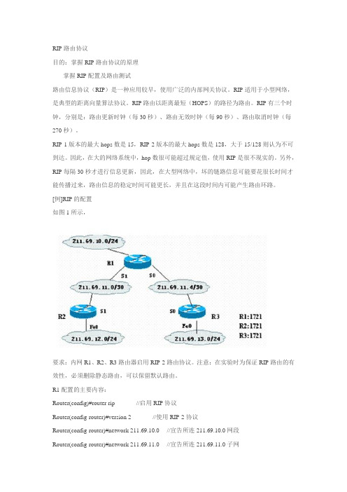
RIP路由协议目的:掌握RIP路由协议的原理掌握RIP配置及路由测试路由信息协议(RIP)是一种应用较早,使用广泛的内部网关协议。
RIP适用于小型网络,是典型的距离向量算法协议。
RIP路由以距离最短(HOPS)的路径为路由。
RIP有三个时钟,分别是:路由更新时钟(每30秒)、路由无效时钟(每90秒)、路由取消时钟(每270秒)。
RIP-1版本的最大hops数是15,RIP-2版本的最大hops数是128,大于15/128则认为不可到达。
因此,在大的网络系统中,hop数很可能超过规定值,使用RIP是很不现实的。
另外,RIP每隔30秒才进行信息更新,因此,在大型网络中,坏的链路信息可能要花很长时间才能传播过来,路由信息的稳定时间可能更长,并且在这段时间内可能产生路由环路。
[例]RIP的配置如图1所示,要求:内网R1、R2、R3路由器启用RIP-2路由协议。
注意:在实验时为保证RIP路由的有效性,必须删除静态路由,可以保留默认路由。
R1配置的主要内容:Router(config)#router rip //启用RIP协议Router(config-router)#version 2 //使用RIP-2协议Router(config-router)#network 211.69.10.0 //宣告所连211.69.10.0网段Router(config-router)#network 211.69.11.0 //宣告所连211.69.11.0子网Router(config-router)#network 211.69.11.4 //宣告所连211.69.11.4子网其它路由器的主要配置步骤对于R2,将所连211.69.12.0、211.69.11.0网段宣告出来即可;对于R3,将所连211.69.13.0、211.69.11.4网段宣告出来即可。
RIP配置完成后,可使用“show ip route”显示IP路由选择表。
eNSP:配置单区域的OSPF网络

eNSP实验:配置单区域的OSPF网络一、实验目的1、理解Route-id的意义2、掌握配置单区域的OSPF网络的方法3、理解OSPF hello-interval和dead-interval的意义二、实验拓扑三、实验步骤1、基本的配置与OSPF配置AR1:sysysname AR1int Gi 0/0/0ip add 192.168.12.1 30int loop 0ip add 1.1.1.1 32qospf 1 router-id 1.1.1.1area 0network 192.168.12.0 0.0.0.3network 1.1.1.1 0.0.0.0qqsave[AR1]sysysname AR2int Gi 0/0/0ip add 192.168.12.2 30int Gi 0/0/1ip add 192.168.23.1 30int loop 0ip add 2.2.2.2 32qospf 1 router-id 2.2.2.2 area 0network 192.168.12.0 0.0.0.3 network 192.168.23.0 0.0.0.3 network 1.1.1.1 0.0.0.0qqsave[AR2]AR3:sysysname AR3int Gi 0/0/0ip add 192.168.23.2 30int loop 0ip add 3.3.3.3 32qospf 1 router-id 3.3.3.3 area 0network 192.168.23.0 0.0.0.3 network 3.3.3.3 0.0.0.0qq[AR3]说明:一台路由器如果要运行OSPF协议,必须存在Router ID。
路由器的ID是一个32比特无符号整数,是一台路由器在自治系统中的唯一标识。
路由器的ID可以手工配置,如果没有通过命令指定ID号,系统会从当前接口的IP地址中自动选取一个作为路由器的ID号。
华为eNSP实训配置+工程图
任务说明:两边单臂路由,Switch 1 三层路由Router 1 eigrg路由,Router 2 ,3, 4 ospf路由,2、3区域0。
3, 4 区域1,Router 2 双向重分发。
R1-----------------system-viewuser-interface console 0idle-timeout 0 0quitsysname R1interface g0/0/0.1control-vid 10 dot1q-terminationdot1q termination vid 10arp broadcast enableip address 10.1.1.254 24interface g0/0/0.2control-vid 20 dot1q-terminationdot1q termination vid 20arp broadcast enableip address 20.1.1.254 24qint s0/0/0ip add 172.16.12.1 24quitripversion 2un summarynetwork 10.0.0.0net 20.0.0.0net 172.16.0.0R2----------------------system-viewuser-interface console 0idle-timeout 0 0quitsysname R2int s0/0/0ip add 172.16.12.2 24int s0/0/1ip add 172.16.23.2 24qrouter id 2.2.2.2ospf 1area 0network 172.16.23.2 0.0.0.0 qripversion 2un summarynetwork 172.16.0.0import-route ospf cost 1 ospf 1import-route rip cost 2R3----------------------------- system-viewuser-interface console 0idle-timeout 0 0quitsysname R3int s0/0/1ip add 172.16.23.3 24int s0/0/2ip add 172.16.34.3 24qrouter id 3.3.3.3ospf 1area 0net 172.16.23.3 0.0.0.0 area 2net 172.16.34.3 0.0.0.0qR4---------------------------system-viewuser-interface console 0idle-timeout 0 0quitsysname R4interface e0/0/0.1control-vid 30 dot1q-termination dot1q termination vid 30arp broadcast enableip address 192.168.30.254 24 interface e0/0/0.2control-vid 40 dot1q-termination dot1q termination vid 40arp broadcast enableip address 192.168.40.254 24qint s0/0/2ip add 172.16.34.4 24qrouter id 4.4.4.4ospf 1area 1net 172.16.34.4 0.0.0.0net 192.168.30.254 0.0.0.0net 192.168.40.254 0.0.0.0S1--------------------------system-viewuser-interface console 0idle-timeout 0 0quitsysname S1int g0/0/1port link-type accessport default vlan 10int g0/0/2port link-type accessport default vlan 20interface g0/0/3port link-type trunkport trunk allow-pass vlan allqvlan batch 10 20interface vlanif 10ip add 10.1.1.254 24 interface vlanif 20ip add 20.1.1.254 24S4------------------------- system-viewuser-interface console 0 idle-timeout 0 0quitsysname S4interface eth-trunk 1int g0/0/1eth-trunk 1int g0/0/2eth-trunk 1quitvlan batch 30 40interface et0/0/2port link-type accessport default vlan 30 interface et0/0/3port link-type accessport default vlan 40 interface ethernet 0/0/1 port link-type trunkport trunk allow-pass vlan all quitinterface Eth-Trunk 1port link-type trunkport trunk allow-pass vlan all R5------------------------- system-viewuser-interface console 0 idle-timeout 0 0quitsysname S5vlan batch 30 40interface et0/0/3port link-type accessport default vlan 30 interface et0/0/4port link-type accessport default vlan 40quitinterface eth-trunk 1 trunkport g0/0/1 trunkport g0/0/2quitinterface Eth-Trunk 1port link-type trunkport trunk allow-pass vlan all S3- --- S2-----无需配置。
华为路由器OSPF配置实例
OSPF上机-1拓扑图1、组网和区域划分如上图所示。
2.在S3526-1、AR28-1、AR28-2、S3526-2的互联接口上启用ospf路由协议;并且在每台三层设备上引入直联路由,直联路由引入按照默认的type 2类型,R1<Huawei>undo terminal monitorInfo: Current terminal monitor is off.<Huawei>system-<Huawei>system-viewEnter system view, return user view with Ctrl+Z.[Huawei]int e0/0/0[Huawei-Ethernet0/0/0]ip add 172.16.0.1 24[Huawei-Ethernet0/0/0]int e[Huawei-Ethernet0/0/0]int[Huawei-Ethernet0/0/0]int e0/0/1[Huawei-Ethernet0/0/1]ip add 192.168.0.5 30[Huawei-Ethernet0/0/1]qui[Huawei]inter[Huawei]interface loopback 0[Huawei-LoopBack0]ip add 1.1.1.1 32[Huawei-LoopBack0]qui[Huawei]router id 1.1.1.1[Huawei]ospf[Huawei-ospf-1]area 1[Huawei-ospf-1-area-0.0.0.1]network 192.168.0.4 0.0.0.3[Huawei-ospf-1-area-0.0.0.1]qui[Huawei-ospf-1]import-route direct[Huawei-ospf-1]silent-interface loopback 0[Huawei-ospf-1]R2<Huawei>undo terminal monitorInfo: Current terminal monitor is off.<Huawei>system-viewEnter system view, return user view with Ctrl+Z.[Huawei]interface Ethernet0/0/0[Huawei-Ethernet0/0/0]ip add 192.168.0.6 30[Huawei-Ethernet0/0/0]int e0/0/1[Huawei-Ethernet0/0/1]ip add 192.168.0.1 30[Huawei-Ethernet0/0/1]qui[Huawei]inter loopback 0[Huawei-LoopBack0]ip add 1.1.1.2 32[Huawei-LoopBack0]qui[Huawei]router id 1.1.1.2[Huawei]ospf[Huawei-ospf-1]area 0[Huawei-ospf-1-area-0.0.0.0]network 192.168.0.0 0.0.0.3[Huawei-ospf-1-area-0.0.0.0]network 1.1.1.2 0.0.0.0[Huawei-ospf-1-area-0.0.0.0]qui[Huawei-ospf-1]area 1[Huawei-ospf-1-area-0.0.0.1]network 192.168.0.4 0.0.0.3[Huawei-ospf-1-area-0.0.0.1]qui[Huawei-ospf-1]R3<Huawei>undo terminal monitorInfo: Current terminal monitor is off.<Huawei>system-viewEnter system view, return user view with Ctrl+Z.[Huawei]int e0/0/0[Huawei-Ethernet0/0/0]ip add 192.168.0.2 30[Huawei-Ethernet0/0/0]int e0/0/1[Huawei-Ethernet0/0/1]ip add 192.168.0.9 30[Huawei-Ethernet0/0/1]qui[Huawei]inter loop 0[Huawei-LoopBack0]ip add 1.1.1.3 32[Huawei-LoopBack0]qui[Huawei]router id 1.1.1.3[Huawei]ospf[Huawei-ospf-1]area 0进入骨干区域,宣告路由信息[Huawei-ospf-1-area-0.0.0.0]net[Huawei-ospf-1-area-0.0.0.0]network 192.168.0.0 0.0.0.3[Huawei-ospf-1-area-0.0.0.0]network 1.1.1.3 0.0.0.0[Huawei-ospf-1-area-0.0.0.0]qui[Huawei-ospf-1]area 2[Huawei-ospf-1-area-0.0.0.2]network 192.168.0.8 0.0.0.3R4<Huawei>undo ter mInfo: Current terminal monitor is off.<Huawei>sysEnter system view, return user view with Ctrl+Z.[Huawei]int e0/0/0[Huawei-Ethernet0/0/0]ip add 192.168.0.10 30[Huawei-Ethernet0/0/0]int e0/0/1[Huawei-Ethernet0/0/1]ip add 172.16.1.1 24[Huawei-Ethernet0/0/1]qui[Huawei]inter loop 0[Huawei-LoopBack0]ip add 1.1.1.4 32[Huawei-LoopBack0]qui[Huawei]router id 1.1.1.5[Huawei]ospf[Huawei-ospf-1]area 2[Huawei-ospf-1-area-0.0.0.2]network 192.168.0.8 0.0.0.3[Huawei-ospf-1-area-0.0.0.2]qui[Huawei-ospf-1]import-route direct cost 100(引入直连开销值为100) [Huawei-ospf-1][Huawei-ospf-1]import-route direct type 1(进入type 1 .第一类外部路由)上机 2组网互联要求-1:1、链路COST值和区域划分如上图所示。
华为eNSP配置实例8——RIP v2路由汇总
•。
在R1上查看路由表,已变为汇总路由
• <R1>dis ip rout
• Route Flags: R - relay, D - download to fib • -----------------------------------------------------------------------------• Routing Tables: Public • • • • • • • • • • • •
步骤二. RIPv2协议配置
• 在R1上启动RIP协议,并将10.0.0.0网段通告到RIP协议。
[R1]rip 1 [R1-rip-1]network 10.0.0.0 [R2-rip-1]version 2 • 在R2上启动RIP协议,并将10.0.0.0网段通告到RIP协议。 [R2]rip 1 [R2-rip-1]network 10.0.0.0 [R2-rip-1]version 2 • 在R3上启动RIP协议,并将10.0.0.0、172.0.0.0 这两个个网段通告到RIP协议。 [R3]rip 1 [R3-rip-1]net 10.0.0.0 [R3-rip-1]network 172.16.0.0 [R3-rip-1]version 2
• R3的基本配置
• <Huawei>undo ter mon • Info: Current terminal monitor is off.
• <Huawei>sys
• Enter system view, return user view with Ctrl+Z. • [Huawei]sysname R3
动态路由协议RIP、OSPF配置
实验二动态路由协议RIP、OSPF配置一、实验目的(1)掌握RIP、OSPF协议的配置方法(2)掌握查看RIP、OSPF协议产生的路由(3)熟悉广域网电缆的连接方式二、实验内容:(一)动态路由协议RIP配置-三层交换机1绘制拓扑图2配置PC的IP、掩码、网关分别:PC1 192.168.1.2 255.255.255.0 192.168.1.1PC2 192.168.2.2 255.255.255.0 192.168.2.13.三层交换机配置(1)划分VLAN,将接口划分到对应的VLAN中(2)配置每个虚接口(VLAN)的IP(3)配置RIP4 R1上的配置(1)配置配置两个接口的IP和串口时钟(2)配置RIP协议:发布直连路由5.R2上的配置(1)配置配置两个接口的IP(2)配置RIP协议:发布直连路由6测试1、分别在R1R2上查看路由表2、在PC1中ping PC2三、实验步骤1绘制拓扑图2配置PC的IP、掩码、网关分别:PC1 192.168.1.2 255.255.255.0 192.168.1.1PC2 192.168.2.2 255.255.255.0 192.168.2.13.三层交换机配置(1)划分VLAN,将接口划分到对应的VLAN中(2)配置每个虚接口(VLAN)的IP(3)配置RIP(3)配置RIP协议:发布直连路由4 R1上的配置(1)配置配置两个接口的IP和串口时钟(2)配置RIP协议:发布直连路由5.R2上的配置(1)配置配置两个接口的IP (2)配置RIP协议:发布直连路由6测试四、实验感想这次试验掌握了RIP、OSPF协议的配置方法,同时也熟悉了广域网电缆的连接方式。
老师通过课堂演示和详细的讲解,再结合发的视频解析,我们对这次的实验掌握的比较好。
这让我体会到,只要认真去做,肯下功夫,对问题仔细分析,拿出不懂就问的精神,自己遇到的问题都可以解决。
[此文档可自行编辑修改,如有侵权请告知删除,感谢您的支持,我们会努力把内容做得更好]。
- 1、下载文档前请自行甄别文档内容的完整性,平台不提供额外的编辑、内容补充、找答案等附加服务。
- 2、"仅部分预览"的文档,不可在线预览部分如存在完整性等问题,可反馈申请退款(可完整预览的文档不适用该条件!)。
- 3、如文档侵犯您的权益,请联系客服反馈,我们会尽快为您处理(人工客服工作时间:9:00-18:30)。
华为eNsp关于RIP协议和OSPF协议的配置文档及拓扑图
每一个路由器的配置文档:
R1:
<Huawei>sys
[Huawei]undo info-center enable
[Huawei]interface giga 0/0/0
[Huawei-GigabitEthernet0/0/0]ip address 192.168.10.1 24 [Huawei-GigabitEthernet0/0/0]interface giga 0/0/2 [Huawei-GigabitEthernet0/0/2]ip address 192.168.1.1 24 [Huawei-GigabitEthernet0/0/2]q
[Huawei]rip 1
[Huawei-rip-1]ver 2
[Huawei-rip-1]network 192.168.1.0
[Huawei-rip-1]q
[Huawei]ospf 1
[Huawei-ospf-1]area 0
[Huawei-ospf-1-area-0.0.0.0]network 192.168.10.0 0.0.0.255 [Huawei-ospf-1-area-0.0.0.0]network 192.168.1.0 0.0.0.255 [Huawei-ospf-1-area-0.0.0.0]
[Huawei-ospf-1-area-0.0.0.0]q
[Huawei-ospf-1]q
R2:
<Huawei>sys
[Huawei]undo info-center enable
[Huawei]interface giga 0/0/0
[Huawei-GigabitEthernet0/0/0]ip address 192.168.10.2 24 [Huawei-GigabitEthernet0/0/0]interface giga 0/0/1 [Huawei-GigabitEthernet0/0/1]ip address 192.168.12.1 24 [Huawei-GigabitEthernet0/0/1]q
[Huawei]rip 1
[Huawei-rip-1]ver 2
[Huawei-rip-1]network 192.168.12.0
[Huawei-rip-1]q
[Huawei]ospf 1
[Huawei-ospf-1]area 0
[Huawei-ospf-1-area-0.0.0.0]network 192.168.10.0 0.0.0.255 [Huawei-ospf-1-area-0.0.0.0]network 192.168.12.0 0.0.0.255 [Huawei-ospf-1-area-0.0.0.0]q
[Huawei-ospf-1]q
R3:
<Huawei>sys
[Huawei]undo info-center enable
[Huawei]interface giga 0/0/0
[Huawei-GigabitEthernet0/0/0]ip address 192.168.12.2 24 [Huawei-GigabitEthernet0/0/0]interface giga 0/0/2 [Huawei-GigabitEthernet0/0/2]ip address 192.168.15.1 24 [Huawei-GigabitEthernet0/0/2]q
[Huawei]rip 1
[Huawei-rip-1]ver 2
[Huawei-rip-1]network 192.168.12.0
[Huawei-rip-1]network 192.168.15.0
[Huawei]ospf 1
[Huawei-ospf-1]area 0
[Huawei-ospf-1-area-0.0.0.0]network 192.168.12.0 0.0.0.255 [Huawei-ospf-1-area-0.0.0.0]network 192.168.15.0 0.0.0.255 [Huawei-ospf-1-area-0.0.0.0]q
[Huawei-ospf-1]q
R4:
<Huawei>sys
[Huawei]undo info-center enable
[Huawei]interface giga 0/0/0
[Huawei-GigabitEthernet0/0/0]ip address 192.168.15.2 24 [Huawei-GigabitEthernet0/0/0]interface giga 0/0/1 [Huawei-GigabitEthernet0/0/1]ip address 192.168.3.1 24 [Huawei-GigabitEthernet0/0/1]q
[Huawei]rip 1
[Huawei-rip-1]ver 2
[Huawei-rip-1]network 192.168.15.0
[Huawei-rip-1]network 192.168.3.0
[Huawei-rip-1]q
[Huawei-ospf-1]area 0
[Huawei-ospf-1-area-0.0.0.0]network 192.168.15.0 0.0.0.255 [Huawei-ospf-1-area-0.0.0.0]network 192.168.3.0 0.0.0.255 [Huawei-ospf-1-area-0.0.0.0]q
[Huawei-ospf-1]q。