中速柴油机新重油共轨系统
柴油机共轨系统
柴油机共轨系统[来源:本网讯 2006/12/26](日)伊藤泶次古田克则【摘要】虽然柴油机热效率高,但排放法规的强度也在逐年增加。
为此,近年来,具有高度柔性控制的、能进行超高压喷射的共轨系统已逐渐成为主流。
介绍了共轨系统的结构、运行、特性及其主要部件??供油泵和喷油器的技术和未来发展趋势。
1 前言与汽油机相比,柴油机热效率高,也就是说在燃油耗方面占有优势,因此在热衷环保的欧洲,柴油车占据汽车总产量的40%。
另一方面,从防止大气污染的观点出发,颗粒(PM)和NOx的排放法规日趋严格,为了应对严格的排放法规,就必须实现燃油的高压喷射化和高度的喷油控制。
本文介绍在近年来可实现超高压喷射且控制自由度高的共轨喷油系统中供油泵和喷油器的相关技术及其今后的发展动向。
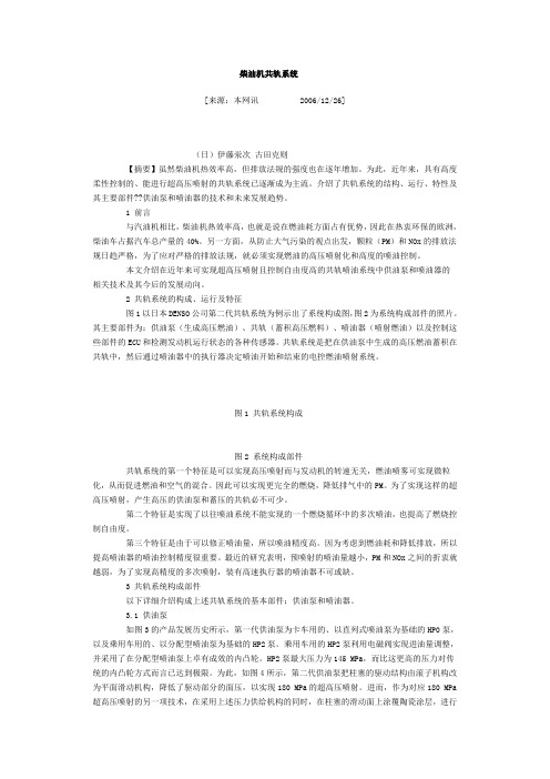
2 共轨系统的构成、运行及特征图1以日本DENSO公司第二代共轨系统为例示出了系统构成图,图2为系统构成部件的照片。
其主要部件为:供油泵(生成高压燃油)、共轨(蓄积高压燃料)、喷油器(喷射燃油)以及控制这些部件的ECU和检测发动机运行状态的各种传感器。
共轨系统是把在供油泵中生成的高压燃油蓄积在共轨中,然后通过喷油器中的执行器决定喷油开始和结束的电控燃油喷射系统。
图1 共轨系统构成图2 系统构成部件共轨系统的第一个特征是可以实现高压喷射而与发动机的转速无关,燃油喷雾可实现微粒化,从而促进燃油和空气的混合。
因此可以实现更完全的燃烧,降低排气中的PM。
为了实现这样的超高压喷射,产生高压的供油泵和蓄压的共轨必不可少。
第二个特征是实现了以往喷油系统不能实现的一个燃烧循环中的多次喷油,也提高了燃烧控制自由度。
第三个特征是由于可以修正喷油量,所以喷油精度高。
因为考虑到燃油耗和降低排放,所以提高喷油器的喷油控制精度很重要。
最近的研究表明,预喷射的喷油量越小,PM和NOx之间的折衷就越弱,为了实现高精度的多次喷射,装有高速执行器的喷油器不可或缺。
3 共轨系统构成部件以下详细介绍构成上述共轨系统的基本部件:供油泵和喷油器。
柴油国四共轨发动机控制系统和部件功能概述

空燃比控制策略
空燃比控制策略是柴油国四共轨发动机控制系统的重要环节,其目标是确保发动机在各种工况下的最 佳燃烧状态,从而提高发动机的动力性和经济性。
空燃比控制策略通过调节燃油喷射量和进气量,使发动机的空燃比保持在最佳值。此外,该策略还考虑 了发动机的转速、负荷、水温、油温等参数,以实现最优的燃烧效果。
柴油国四共轨发动机 控制系统和部件功能 概述
REPORTING
https://
目录
• 引言 • 柴油国四共轨发动机控制系统概述 • 柴油国四共轨发动机主要部件功能 • 柴油国四共轨发动机控制策略 • 柴油国四共轨发动机控制系统的发展趋势与
展望 • 结论
PART 01
柴油国四共轨发动机控制系统采用了 开环和闭环相结合的控制方式,通过 怠速电机、节气门位置传感器等传感 器实时监测发动机的工作状态,并根 据监测结果进行实时调整,以实现怠 速控制的最佳效果。
PART 05
柴油国四共轨发动机控制 系统的发展趋势与展望
REPORTING
WENKU DESIGN
智能化控制
通过深入了解柴油国四共轨发动机控制系统的原理和部件功能,有助于提高发动 机的性能和排放水平,为相关领域的研发和应用提供理论支持和实践指导。
PART 02
柴油国四共轨发动机控制 系统概述
REPORTING
WENKU DESIGN
控制系统组成
01
02
03
传感器
用于检测发动机的工作状 态和参数,如油轨压力、 冷却液温度、进气压力等。
引言
REPORTING
柴油机共轨系统
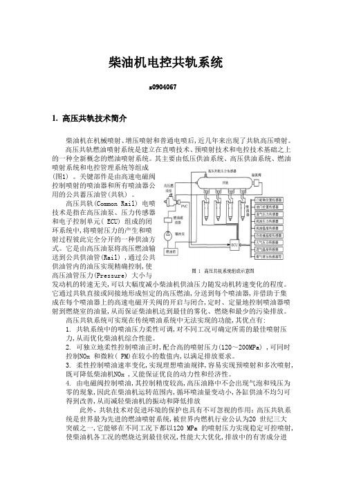
柴油机电控共轨系统s09040671.高压共轨技术简介柴油机在机械喷射、增压喷射和普通电喷后,近几年来出现了共轨高压喷射。
高压共轨燃油喷射系统是建立在直喷技术、预喷射技术和电控技术基础之上的一种全新概念的燃油喷射系统。
其主要由低压供油系统、高压供油系统、燃油喷射系统和电控管理系统等组成(图1) 。
关键部件是由高速电磁阀控制喷射的喷油器和所有喷油器公用的公共蓄压油管(共轨) 。
高压共轨(Common Rail) 电喷技术是指在高压油泵、压力传感器和电子控制单元( ECU) 组成的闭环系统中,将喷射压力的产生和喷射过程彼此完全分开的一种供油方式。
它是由高压油泵将高压燃油输送到公共供油管(Rail) ,通过公共供油管内的油压实现精确控制,使高压油管压力(Pressure) 大小与发动机的转速无关,可以大幅度减小柴油机供油压力随发动机转速变化的程度。
它通过共轨直接或间接地形成恒定的高压燃油,分送到每个喷油器,并借助于集成在每个喷油器上的高速电磁开关阀的开启与闭合,定时、定量地控制喷油器喷射到燃烧室的油量,从而保证柴油机达到最佳的雾化、燃烧和最少的污染排放。
高压共轨系统可实现在传统喷油系统中无法实现的功能,其优点有:1. 共轨系统中的喷油压力柔性可调,对不同工况可确定所需的最佳喷射压力,从而优化柴油机综合性能。
2. 可独立地柔性控制喷油正时,配合高的喷射压力(120~200MPa) ,可同时控制NOx 和微粒( PM)在较小的数值内,以满足排放要求。
3. 柔性控制喷油速率变化,实现理想喷油规律,容易实现预喷射和多次喷射,既可降低柴油机NOx ,又能保证优良的动力性和经济性。
4. 由电磁阀控制喷油,其控制精度较高,高压油路中不会出现气泡和残压为零的现象,因此在柴油机运转范围内,循环喷油量变动小,各缸供油不均匀可得到改善,从而减轻柴油机的振动和降低排放此外,共轨技术对促进环境的保护也具有不可忽视的作用:高压共轨系统是世界最为先进的燃油喷射系统,被世界内燃机行业公认为20 世纪三大突破之一,它能够在不同工况下都以120 MPa 的喷射压力实现稳定可控喷射,使柴油机各工况的燃烧达到最佳状况,性能大大优化,排放中的有害成分进一步减少。
柴油共轨系统发动

柴油共轨发动机实训台目录一、简介............................................................. - 3 -二、技术性能......................................................... - 3 -三、使用前的准备工作................................................. - 6 -四、具体功能及操作方法............................................... - 7 -五、注意事项........................................................ - 11 -六、维修使用资料.................................................... - 12 -一、简介本发动机实训台是本公司采用德国BOSCHEDC16控制系统的电控共轨柴油发动机为适应汽车教学需求而研制,该实训台由发动机总成(新机)、操作显示面板、可移动台架、汽油箱、散热器、蓄电池、排气管并配置原车发动机ECU、各传感器执行器等组成。
其结构紧凑、操作方便、安全可靠、教学直观,具有发动机运转及显示、自诊断、发动机数据分析、故障设置、各传感器信号检测及模拟、扩展通讯等多项功能。
是汽车发动机实物教学不可缺少的实验室设备。
二、技术性能1、主要参数值:设备名称:共轨柴油发动机实训台设备车型:长城设备类型:电控发动机实训台设备规格:1650*1000*1800mm设备重量:360kg设备颜色:白色设备电源:DC/12V设备发动机相关数据:2、整体实物图片三、使用前的准备工作1、实训台应安装在具有发动机尾气排放装置的场所。
2、安装场地应平整结实。
3、使用滚轮移动台架后,应将万向轮锁止以免滑移。
船用柴油机共轨式电控燃油喷射技术应用研究

结果与讨论
通过问卷调查和实地调研,我们了解到柴油机中压共轨液力增压式电控燃油 喷射系统在国内外已经得到了广泛的应用,尤其在工程机械、农业机械等领域, 其具有的优异性能得到了用户的一致好评。在实验室实验中,我们发现该系统具 有以下优点:(1)喷油压力稳定,喷油品质好;(2)喷油规律可调,能够满足 不同工况的需求;(3)响应速度快,喷射过程迅速;(4)节能环保,降低了柴 油机的油耗和排放。
3、通过引入故障诊断和容错控制策略,系统的可靠性得到了显著提升,减 少了船舶动力系统的故障概率。
五、总结与展望
本次演示通过对船用中速柴油机高压共轨燃油喷射系统的研究,提出了一种 新型的喷射系统设计方案。该方案在提高燃油喷射压力控制精度、可靠性和节能 效果方面具有显著优势。实验结果表明,本次演示设计的系统在各方面均优于传 统燃油喷射系统。然而,仍存在一些不足之处,例如如何进一步提高系统的自适 应能力和智能化水平等。
谢谢观看
文献综述
在过去的研究中,针对柴油机燃油喷射系统的改进主要集中在提高喷油压力、 改善喷油品质、优化喷油规律等方面。其中,中压共轨液力增压式电控燃油喷射 系统作为一种新型的喷射技术,具有突出的优势。在研究中,我们发现先前的研 究主要集中在系统的喷油压力、喷油量、喷油始点等参数的优化方面,而对于该 系统的综合性能评估和优化研究相对较少。
研究方法
本研究采用了问卷调查、实地调研和实验室实验相结合的方法,对柴油机中 压共轨液力增压式电控燃油喷射系统进行了全面研究。首先,我们通过问卷调查 收集了国内外相关研究机构和企业对该系统的认知和应用情况。其次,我们实地 调研了应用该系统的柴油机运行状况和实际应用领域。最后,我们设计了实验室 实验,对不同型号的柴油机进行了系统的性能测试和评估。
重卡柴油机高压共轨系统

凸轮轴壳体组件
凸轮由发动机曲轴驱动 机油润滑 与齿轮泵同轴驱动
三角凸轮驱动柱塞
高压共轨管道
体积大,能保证稳定的油压,使轨道压力不 受发动机转速影响而独立控制。
轨道压力超过一定值时,高压泄压阀打开, 轨道内压力下降至一定数值,然后才能正常使用。
问题分析
6.燃油沿着针阀上行流到回油管,针阀开启慢 7.电磁柱塞锥端磨损:始终回油,严重时不能喷油 8.量孔堵塞:喷油器一直在滴油 9.高压连接管泄露:缸体回油增多,甚至是发动机 无法起动——断缸堵
柴油机高压共轨系统
电控高压共轨系统的介绍 高压共轨系统的燃油流程 高压共轨系统组件介绍 高压共轨系统常见故障
• 这会使针阀自关闭位置升 起。
• 燃油这时会通过喷嘴喷入 气缸。
喷油器工作原理
•当不需要喷射燃油时ECM会使 喷油器电磁阀断电。 • 电磁力消失可以允许弹簧压下 电磁阀到关闭位置。 • 当电磁阀在关闭位置时泄油通 道就被关闭。 • 当泄油通道关闭时,柱塞上部 较大的受力面积将使柱塞/针阀 复位以终结燃油喷射。
喷油器的安装
喷油器的安装五步法 更换新的O型圈,检查喷油器垫片,润滑O型圈, 将喷油器按正确方向导入气缸盖孔 拧上喷油器压紧螺栓但不要拧紧。 安装高压连接管,确保高压连接管接头末端处于喷油器进口端 口中,预拧紧高压连接管接头。 拧紧喷油器压紧螺栓。 拧紧高压连接管固定螺母。
燃油系统测试
燃油油轨
往各缸的高压油管
喷油器工作原理
• 当ECM需要燃油进入一个气 缸时,一个电压信号就会给 到电磁阀。
• 这会产生一个比弹簧力更大 的电磁力
•这会使电磁阀金属芯向上移 动。
柴油共轨工作原理
柴油共轨工作原理
柴油共轨系统是一种先进的柴油机燃油喷射系统,它的工作原理相比传统的喷
油系统有着显著的优势。
本文将从柴油共轨系统的组成结构和工作原理两个方面进行介绍。
首先,我们来了解一下柴油共轨系统的组成结构。
柴油共轨系统主要由高压泵、共轨、喷油嘴和压力控制阀等组成。
高压泵负责将柴油加压至很高的压力,然后通过共轨将高压柴油储存起来,最后通过压力控制阀控制喷油嘴的喷油时机和喷油量。
接下来,我们来介绍柴油共轨系统的工作原理。
在柴油共轨系统中,高压泵将
柴油加压至非常高的压力,然后通过共轨将高压柴油储存起来。
当发动机控制单元发出喷油指令时,压力控制阀会控制喷油嘴的喷油时机和喷油量,使得喷油嘴可以将高压柴油喷射到燃烧室内。
由于柴油被加压储存,因此喷油嘴可以通过电磁阀控制高压柴油的喷射时间和喷射量,从而实现精确的喷油控制。
柴油共轨系统的工作原理可以说是高压泵、共轨、喷油嘴和压力控制阀等部件
协同工作的结果。
高压泵提供高压柴油,共轨储存高压柴油,压力控制阀控制喷油嘴的喷油时机和喷油量,喷油嘴将高压柴油喷射到燃烧室内。
这种精确的喷油控制能够大大提高柴油机的燃烧效率,降低排放,提高动力性能。
总的来说,柴油共轨系统通过精确控制喷油时机和喷油量,提高了柴油机的燃
油利用率和动力性能,降低了排放。
它是一种非常先进的柴油机燃油喷射系统,未来将会得到更广泛的应用。
L3244CR柴油机燃油共轨系统简介
157中国设备工程Engineer ing hina C P l ant中国设备工程 2019.03 (上)1 燃油系统共轨柴油机燃油系统组成有低压燃油系统,共轨与喷射系统,清洗与安全系统和燃油泄漏系统(图1)。
1.1 低压燃油系统低压燃油系统组成集中式供油单元,为机器提供10~12bar 的燃料用油,包括:供应泵吸口双联滤器、供油泵及增压泵、带反冲洗功能的自清滤器、旁通滤器及相关部件。
1.2 共轨燃油与喷射系统(图2)在共轨喷射系统中,压力油由电子控制的高压油泵输出燃油至共轨蓄压器保压,电子驱动阀组用来决定燃油喷射的开始、连续及停止时间,而与柴油机的转速和喷射量无关。
图2 32/44CR 共轨系统概述对于系统建压,L32/44CR 共轨系统中没有独立机械油泵,只有通过柴油机凸轮驱动的高压油泵。
共轨高压油泵与传统机械控制式柴油机高压油泵不同之处在于没有齿条,通过高压油泵自带的由电子控制的节流阀实现单缸油量控制。
低压系统燃油经节流阀进入高压油泵后排入串联的共轨桶,通过高压油管可以将所有的共轨桶串联。
在共轨桶2端或1端装有阀组,通过安装在下部的1个单向溢流阀至低压系统,该单向溢流阀可以将喷油器喷射完成后的管内余压进行卸压,单缸燃油喷射的时间及油量可以通过电子控制阀组完成。
L32/44CR 柴油机燃油共轨系统简介盛卫明(中港疏浚有限公司,上海 200120)摘要:L32/44CR 柴油机是一款新型共轨电喷直立式四冲程柴油机,采用共轨式电子喷射系统,可对燃油喷射进行优化从而降低燃油消耗、减少氮氧化物排放。
控制系统采用曼恩自主研发的SaCoSone 系统,该系统集安全、监测和速度控制功能于一体,系统采用CAN 冗余总线方式与柴油机上控制单元进行通讯连接,完成信息交互。
现就该机型的燃油共轨系统和SaCoSone 控制系统进行简单介绍,使轮机管理人员加深对设备认识,增强管理经验,提升设备管理水平,保证船舶正常使用。
第2讲 柴油机共轨系统概述
BOSCH压电式共轨喷油器
压电式 共轨 ECU
The engineers managed to reduce the moving mass by 75% and the number of moving parts on the nozzle needle from four to one. “This allows them to switch twice as fast as conventional magnetic and piezoelectric injectors,” said Ulrich Dohle, Director of the Diesel Systems Division at Bosch.
2.采用共轨方式供油,喷油系统压力波动小,各喷油嘴间相互影 响小,喷射压力控制精度较高,喷油量控制较准确。
什么是柴油发动机共轨技术
什么是柴油发动机共轨技术?共轨技术是指高压油泵、压力传感器和ECU组成的闭环系统。
高压油泵把高压燃油输送到公共供油管,通过对公共供油管内的油压实现精确控制,可以大幅度减小柴油机供油压力随发动机转速的变化。
在汽车柴油机中,高速运转使柴油喷射过程的时间只有千分之几秒,实验证明,在喷射过程中高压油管各处的压力是随时间和位置的不同而变化的。
由于柴油的可压缩性和高压油管中柴油的压力波动,使实际的喷油状态与喷油泵所规定的柱塞供油规律有较大的差异。
油管内的压力波动有时还会在主喷射之后,使高压油管内的压力再次上升,达到令喷油器的针阀开启的压力,将已经关闭的针阀又重新打开产生二次喷油现象,由于二次喷油不可能完全燃烧,于是增加了烟度和碳氢化合物(HC)的排放量,油耗增加。
此外,每次喷射循环后高压油管内的残压都会发生变化,随之引起不稳定的喷射,尤其在低转速区域容易产生上述现象,严重时不仅喷油不均匀,而且会发生间歇性不喷射现象。
为了解决柴油机这个燃油压力变化的缺陷,现代柴油机采用了一种称为“共轨”的技术。
共轨系统共轨技术是指高压油泵、压力传感器和ECU组成的闭环系统中,将喷射压力的产生和喷射过程彼此完全分开的一种供油方式,由高压油泵把高压燃油输送到公共供油管,通过对公共供油管内的油压实现精确控制,使高压油管压力大小与发动机的转速无关,可以大幅度减小柴油机供油压力随发动机转速的变化,因此也就减少了传统柴油机的缺陷。
ECU控制喷油器的喷油量,喷油量大小取决于燃油轨(公共供油管)压力和电磁阀开启时间的长短。
柴油机的涡轮增压器已作过介绍。
至于增压中冷技术就是当涡轮增压器将新鲜空气压缩经中段冷却器冷却,然后经进气歧管、进气门流至汽缸燃烧室。
有效的中冷技术可使增压温度下降到50℃以下,有助于减少废气的排放和提高燃油经济性。
关于柴油的小知识。
根据国标(GB252—87),轻柴油规格按凝点分为10、0、-10、-20、-35和-50六个牌号,分别表示凝点不高于10℃、0℃、-10℃、-20℃、-35℃和-50℃;牌号越高,凝点越低。
- 1、下载文档前请自行甄别文档内容的完整性,平台不提供额外的编辑、内容补充、找答案等附加服务。
- 2、"仅部分预览"的文档,不可在线预览部分如存在完整性等问题,可反馈申请退款(可完整预览的文档不适用该条件!)。
- 3、如文档侵犯您的权益,请联系客服反馈,我们会尽快为您处理(人工客服工作时间:9:00-18:30)。
IntroductionThe Diesel engine is and will, also in the future, be one of the most eco-nomic possibilities for converting chemical fuel energy into mechanical energy. This applies both to the automotive range and the propulsion of large vessels or power plant generators. In order to make use of the Diesel engine’s economy also in the future, it will, with regard to environmental aspects, become more and more important to prevent visible and, in particular, pollutant compo-nents from being contained in the exhaust gas. Already at an early stage, MAN B&W attached great importance to this requirement , carried out corresponding develop-ment work and launched exhaust gas optimised engines [1]. Following the philosophy of environment-friendly engine development, CR will, as a next step, be introduced for MANB&W engines.Due to an electronic control system’s degrees of freedom, CR now offers engine developers a considerably wider spectrum of injection curve design, i.e. total combustion will prevent harmful constituents from being produced in the exhaust gas. When taking all possibilities of com-bustion process design into consid-eration, one must be fully aware of the fact that the injection system and, particularly, CR, is one of the most important components of an engine and that the engine is no longer functional if the injection system fails. The development of CR focused, in addition to functionality and represen-tation of the degrees of freedom, particularly on its reliability.In order to take a decisive develop-ment step forward in engine technol-ogy with the help of CR, relevant development targets were precisely fixed. Optimum combustion requires, in addition to the degrees of freedom, i.e. injection start, injection quantityand injection pressure, the realisationof pilot and post injection. As thealready existing engine series is to beequipped with CR, the system had tobe designed in order to permitmounting on the engine withoutconstructive interventions. Due to thisrequirement, the mechatronic compo-nents could not be accommodated inthe cylinder head. As our engines areheavy fuel oil compatible, the fuel-relevant conditions, such as abrasiveand corrosive constituents and hightemperature, must be fulfilled with theutmost reliability and the usualmaintenance intervals.With regard to the success of a newdevelopment, it is of fundamentalimportance that the courses arealready correctly set during thedevelopment phase. For this reason,the different system possibilities,including one and two-circuit sys-tems, were tested in pre-studies onan L 16/24 engine [1]. In this connec-tion, it was very soon evident that thefinal development solution could onlybe a one-circuit system as it provedthat the requirement for a variabledesign of the injection curve can,system-dependent, not be achievedwith a two-circuit system.Pre-studiesFor safeguarding the long termtechnology planning of MAN B&W ’sCR concept different pre-studies weredone. At the experimental tests withthe single circuit system investigationswere done with regard to the materi-als and the necessary productionmethods of the control valves.Furthermore the CR system for basicdevelopments at the engine L16/24was modified with an separate controlvalve at the rail to pre-test a hydraulicconcept as it is described below,where no mechatronic componentsare installed in the cylinder head.The tests showed also at a highengine speed of 1200 rpm very goodengine performance.Furthermore extensive simulationwere done to compare the hydraulicbehaviour of different fuel injectionsystems. At figure 1 a conventionalinjection system is compared to twodifferent kind of CR systems. With thelift controlled system the rail pressurecontinuously is located at the needleseat, with the advantage of fastresponse behaviour. Such kind ofsystems are mainly applied at highspeed Diesel engines in the truck orautomotive market at engine speedsup to 5000 rpm. At another variant ofCR systems the needle lift is control-led by pressure increase like at aconventional system. The pressureexists only during the injection periodat the needle seat, which is animportant safety factor for the applica-tion at medium speed diesel engines.With further matching of the geometryof the throttles inside the control andinjection valve it is possible to adjustalso a very high pressure inside thesac hole of the injection nozzle (figure2). This potential of the pressurecontrolled CR system gives thefreedom for best matching results atengine operation values.System descriptionThe MAN B&W CR injection systemis designed for the use of heavyfuel oil with viscosities of up to 700cSt at 50°C. These fuels have to bepreheated to a temperature of up to150°C in order to reach a suitableinjection viscosity. Another problemwith heavy fuel in electronic controlledinjection systems is the high contentof abrasive particles and aggressivecomponents in these fuels. All partsthat control the injection thereforehave to work under the conditionsof high temperature, high viscosity,New HFO Common Rail Systemfor Medium speed Diesel Engines12highly abrasive particles and aggres-sive components.For large bore diesel engines the ap-plication of a single pressure accumu-lator along the full length of the engine is problematic due to the following reasons:• For heavy fuel operated engines there are big differences in the possible fuel temperature from appr. 25°C up to 150°C. This high temperature differences will result in big differences of rail length caused by thermal expansion.• A long rail always requires radial drillings for the connection to each cylinder. Caused by these drillings very high stresses are unavoid-able. The problems and the coun-termeassures with these stresses increase with the increased inner diameter of the rail necessary for large diesel engines.• In the case with reduced accumu-lator volume it would hardly be possible to reach identical injection ratios for all engine cylinders and excessive pressure fluctuations in the system could not be ruled out.• The possibility to build large bore diesel engines with different cylinder numbers, would lead to a special rail for each cylinder number. • Also connection to a pressure ac-cumulator of excessive length at one place only via the high-pressure pump will result in deviations of the injection quality.It was therefore reasonable to divide the accumulator in several units with a suitable volume and to divide the supply to two high-pressure pumps at least for an 6 cylinder engine. A further advantage of this segmenta-tion is the increased flexibility depend-ing on the engine cylinder number, which is also an interesting factor in the case of retrofit application. Themore compact building units ensureFig. 1: Comparison of different fuel injection systemsFig. 2: Matching of sac hole pressure at part loadFig. 3: Modular rail unit with integrated control valves for different engine typesan improved utilisation of the available space on the engine, which results in advantages during assembly and spare parts storing.Based on the idea of the segmented rail MAN B&W developed a modular system to cover several engine types. Figure 3 shows the rail units for two different engine types 32/40 CR and 48/60B CR. The rail cover including the control valves and further compo-nents are very similar or even equal in its geometry.Layout and functionalityFigure 4 shows the hydraulic scheme of the patented heavy fuel oil CR injection system for the MAN B&W32/40 engine.A low-pressure fuel pump (1) delivers the fuel via electromagnetic activated throttle valves (2) and suction valves (3) to the high-pressure pumps (4), which force the fuel into the pump accumulator (6) by means of pressure valves (5).Each pump is connected to the pump accumulator (6) which samples the fuel delivered by the pumps. From the pump accumulator the fuel flow goes to the accumulator units (7), which areconnected in series to the so called common rail. The accumulator units consist of a compact tube, which is on both front sides equipped with an accumulator cover, which is tightly fixed by a number of cylinder screws. The accumulator covers contain radial connections for the high-pressure pipes leading to the injectors (9) as well as for the connecting pipe to the next accumulator unit. The tube itself doesn’t contain any radial drillings and is therefore easy to produce and very resistant to high fuel pressures.Drive of the high-pressure pumps is, as known, effected by cams arranged on the engine camshaft, which aredesigned as three-lobe-cams in orderto increase and equalise delivery.On account of the interposition ofthe pump accumulator, which is sup-plied by two to four high-pressurepumps, the dynamic pressure wavescan be kept very low. The deliveryquantity of the high-pressure pumpsis calculated by the electronic controlsystem on the basis of an evaluationof the fuel pressure indicated by therail pressure sensor and the cor-responding operation condition ofthe engine. The electro-magneticallyactivated throttle valve (2) in the low-pressure pipe will now suitably meterFig. 4: General layout and functionalitythe fuel quantity supplied to the high-pressure pumps. Each accumulatorcover (figure 5) contains componentsand connections, which serve for fuelsupply and transmission as well asfor fuel injection timing control of theinjectors. On its way from the accu-mulator unit interior to the 3/2-wayvalve and then to the injector, thefuel is passed through a flow limiter.A spring-loaded piston in this com-ponent carries out a stroke for eachinjection, which is proportional to theinjection quantity and returns in itsoriginal position in the time betweenthe injections. Should the injectionquantity exceed however a specified3limit value, the piston will be pressed to a sealing seat at the outlet side at the end of the stroke and will thus avoid permanent injection at the injec-tor.The 3/2-way valve (10) inside the accumulator cover is electro magneti-cally activated by the control system and permits the high-pressure fuelto be supplied from the accumulator unit, via the flow limiter, to the injec-tor. As shown in figure 6 it is operated and controlled without any additional servo fluid by an additional 2/2-way valve. Therefore it is possible to be actuated much faster than an servo oil controlled valve. By a repeated actuation of the 2/2-way valve during the injection process, pre- and post-injection can be obtained. The general concept of the pressure controlled CR system are described in [2]. The functional leakages arising during the control process of the 3/2-way valve will be discharged via separate pipes back into the low pressure system. To ensure that back flow of fuel from the low pressure system into the cylinder is impossible, for instance in the case of a seized needle, in each of these pipes a non-return valve is installed.A safety valve (16) is arranged at the pump accumulator (6), which opensif a specified pressure is exceeded and protects the high-pressure sys-tem against overload.The high-pressure pipes and accumu-lator units are designed with doublewalls in order to prevent fuel from penetrating to the outside in the case of leakage or break of connections. In this case, the operating personnel will be warned by means of the float lever switch.The fuel supply system is provided with a heavy fuel oil preheating sys-tem. For start-up of the cold engine with heavy fuel oil, the high-pressure part of the injection system is heatedby means of circulating hot heavyfuel oil. For this purpose, the flushingvalve (15), located at the end of thelast accumulator unit connected inseries, will be opened pneumatically.The heavy fuel oil will now be pumpedback into the fuel tank from the low-pressure fuel pump (1), throughthe throttle valves (2) and the suctionvalves (3), through the pump chamberFig. 5: Rail cover and integrated componentsFig. 6: Positions of control valve during injectionof the high-pressure pumps (4),via the pump accumulator (6),through the accumulator units (7)and the open scavenging valve (15).After sufficient heating of the injec-tion system, the scavenging valve isclosed and the engine started.The scavenging valve serves alsofor pressure relief of the high-pres-sure part of the injection system in4the case of emergency stop, mainte-nance, repair work and regular engine stop.The supply of high-pressure fuel into the pumped accumulator through two ore more high-pressure pumps offers the advantage that part-load or lean home operation is still possible, if one of the pumps fails.The assembly of the CR system at the engine is shown in figure 7. Advantages of the MAN B&W CR systemBy the use of the separate 3/2-way valve there is only pressure at the injection valve during injection. Thisensures the high safety necessary for ship application because uncontrolled injection is avoided even if the control valve or the injection valve is leaking.By locating the 3/2-way valve in the accumulator cover and using a con-ventional pressure controlled injec-tor, this CR system is easy to use for actual engine designs with their very limited space in the cylinder head. Also the retrofit of conventional fuel injection equipment to CR at engines in service is considerably easier.Pressure waves, which occur in the high-pressure pipes of other CR sys-tems between rail and injector, espe-cially at the end of injection, will thus be avoided. This reduces the load of the components which are exposed to pressure.The modular division of the unitsand the assignment of the individual engine cylinders reduces the expendi-ture of material and assembly work and permits short pipe lengths to the injectors.The concept enables within the hydraulic functionality the features pre- and post-injection (see alsofigure 13 ). Furthermore a shaping ofthe injection rate is possible to adjustthe penetration of the fuel jet duringthe mixture formation (see also figure12 ). At future upgrade the concepthas also the potential for a transientshaping of the injection rate duringthe injection period. By matching thecombustion with this features theengines equipped with the CR systemhave the potential to fulfil also futureemission limits.Safety conceptFor all applications of medium speedengines but especially for the useof these engines on board of ships,safety is one of the most importantitems for design and operation.To ensure that all possible failureswhich are dangerous for the ship arecovered by the safety concept ofthe CR injection system MAN B&Wperformed an extensive FMEA (FailureMode and Effect Analysis) for themechanical/hydraulical part as well asfor the electronic part. For instance inthe mechanical/hydraulical part of theCR injection system 142 hypotheti-cal possible failures were identified.To avoid any negative effects of thesepossible failures 154 detection meas-ures and 232 avoiding measures weredeveloped and introduced.Based on this FMEA the main pointsof the safety concept for the MANB&W Common Rail injection systemare:• Injection pressure only during injec-tion at the injection valveÆNodanger of uncontrolled fuel injectioncaused by leaking control or injec-tion valves.• All high pressure pipes, rails andhigh pressure connections areshieldedÆNo danger of fuel spraythrough leaking or broken pipes.• Fuel limiting valves at each cylinderÆNo danger of uncontrolled injec-tion length.• Non return valves at each cylin-derÆEnsure that fuel back flowfrom the fuel low pressure systemto the cylinder is impossible.• At least two high pressurepumpsÆEmergency operationpossible in the case of a pumpfailure.•Safety valve with additional pres-Fig. 7: Assembly of CR system at a 6 cylinder engine56sure control valve ÆEmergency operation possible in the case of a rail pressure control failure.• 2 Rail pressure sensors and 2speed /TDC pick ups ÆContinued operation in the case of a sensor or pick up failure.The investigation showed that by the introduction of the new CR technology the system itself should be kept as simple as possible includ-ing the safety features. One main important item for a safe technology concept are the following validation tests out of the FMEA method. For these tests additional test rig facilities were installed.ElectronicsThe introduction of CR is a special challenge for the electronics devel-opment as there are no possibilities of having a mechanical redundant backup-system available. While the classification societies allow non re-dundant solutions for multiple engine installations MAN B&W has directed its focus regarding the layout to single engine main propulsion applications. This requires a full “hot” redundant system layout (figure 8).The two ECU’s (electronic control units ) are responsible for the solenoid valve control, the high pressure pump control and therefore the speed gov-erning. Each ECU controls half of the engine but is also able to control the complete engine if the other unit fails. In case of a malfunction the sys-tem can continue the control with one ECU without interrupting the engine operation and with full func-tionality by assigning the actuators to the remaining ECU by means of the switch over modules. All necessary sensors, the power supply and all field bus connections are doubled. So a single failure will never lead to anengine stop. The single PLC is onlyFig. 8: Redundancy of electronic control systemFig. 9: Simulation model for 1 cylinder unitresponsible for communication with the ship alarm system and for the Man Machine Interface.For multiple engine applications there exists also a non redundant version of the CR control which improves sim-plicity and costs.The CR electronics extend the possibilities of the conventional injection systems by allowing pre- and post-injection and of course by using freely adjustable rail pressure and injection timing. A multitude of characteristic maps and param-eters allows to adjust the injection to an optimum for the entire opera ting range. In the future this will be the heart of an engine manage-ment system for a self adapting engine.Development resultsThe development of the MAN B&W CR injection system was divided into five main steps:• Layout and simulation• Design and FMEA• Hydraulic optimization and endur-ance test at injection test rigs• Test and optimization at the test engine• Field test on boardLayout and simulationAs already mentioned the develop-ment started with intensive studiesof the different possibilities to realizea CR injection system. In a very early phase of these studies first simula-tions were started to evaluate the advantages and disadvantages of these variants. After a preselection the simulation tool was then usedto optimize the different parts and to define the frame conditions for the design.But also after design was started, simulation was a very effectivetool to optimize the system already before the first parts were produced. Figure 9 shows a physical and mathematical model for the simulation of a one cylinder unit including the components between rail segment and injection nozzle. Figure 10 illustrates the comparison between the simulation and the test results todemonstrate the good correlation between simulation and reality.But the simulation was not limitedto single cylinder units. To investigate the influence of different cylinder numbers simulation modelsof the complete CR system for upto 9 cyl. were prepared and verified by measurements.Hydraulic optimization and endu-rance test at injection test rigsAs already mentioned the heavy fueloperation is a big challenge for allelectronic controlled injection sys-tems. Therefore MAN B&W decidedto install new test rigs especially forthe hydraulic optimization and endur-ance testing of CR injection systemsunder as realistic conditions as possi-ble. These test rigs are characterizedby the following main features:• Installation of complete CR systemsfor up to 9 cyl. possible.• Fully computerized operation andmeasurement with the possibility ofunmanned endurance runs.• Operation with different test fuels,especially with real heavy fuel oil forendurance tests.Fig. 10: Comparison of simulation and measurementFig. 11: Test rig installation of the complete CR system78Figure 11 shows one of these test rigs with the CR injection system 32/40 installed.Additionally to the test rigs for the hydraulic and endurance test MAN B&W installed an additional test rig to check the calibration of the con-trol valves. Results of the test engine showed the importance of a good calibration of these components. With the precise calibration of the rail cov-ers it was possible to reach the level of exhaust gas temperature deviations of a well adjusted conventional injec-tion system without correction at the electronic side even at very low load points.The optimization of the CR injection system at the injection test rigs shall be demonstrated at a few examples:• Figure 12 shows the measured pressure before the injection valve for three different versions of the control valve compared to the injection pressure curve of the conventional injection system. It is easy to see that the rate of injection at the beginning of injection, which is most important for the NO X - and the smoke formation with the MAN B&W CR system can be optimized in a big range to match the injection system to the requirements of the engine.• Also pre- and post-injection was not only simulated but also tested at the injection test rigs. Figure 13 shows the measured pressure and needle lift for a measuring point with pre- and post-injection.• Not only the electronic control valves are highly loaded and sensi-tive parts for CR injection systems. Also the high pressure pumps are due to the reduced number of pumps (1 high pressure pump for up to 3 cyl.) and the high possible rail pressure (1600 bar) exposed to a very high load. Therefore theyhave to be tested and optimizedFig. 12: Matching of the rate of injectionFig. 13: Pre- and post injection very extensive. For instance figure 14 shows the influence of the rail pressure on the temperature in the pump barrel close to the plungerbore. This temperature is increas-ing significantly with increased pressure. But by a modified pump element which improved cooling and lubrication it was possible to reduce this temperature peak to an acceptable level.• The possibility to operate the CRinjection system with original heavyfuel oil over long operation periods at the test rigs also showed wear problems far before they would be seen on a test engine or in the field.Figure 15 shows on the left side the piston of the control valve in the first version. Already after a short oper-ating time cavitation was visible and measurable. To reduce this cavita-tion the flow geometry was opti-mized by CFD calculations and the modified parts were tested again. The picture on the right side shows the same area after appr. 2500 h and demonstrates the significant improvement.Also on the piston which controls the control cut off area unaccept-able wear was found at the begin-ning of the system tests. (figure 16 top). But after some optimizations steps also at this position a good running behavior could be reached (figure 16 bottom)Enigine resultsDemands on exhaust gas emis-sions of medium-speed Diesel enginesIn addition to compliance with IMO regulations, it must, these days, be ensured that the exhaust gas is invisible and cannot be proven as smoke at the funnel. Already at an early stage, MAN B&W Diesel ad-dressed themselves to the develop-ment of an engine with invisible exhaust gas over the complete load range.Performance data of the 32/40CR engineThe 32/40 engine is used as main and auxiliary marine engine, in stationary power generation plants as well asfor special applications, e.g., in the offshore range. The engine is gener-ally loaded at a constantly rated engine speed of 750, resp. 720 rpm. In individual cases it can, however, also be operated in the so-called combinator or propeller mode within a speed range of between 450 and 750 rpm. In these operating modes, the engine is increasingly loadedat rising engine speeds.When the engine is operated onheavy fuel oil of medium quality, thefuel is heated to a supply temperatureof approx. 150°C in order to reach afuel viscosity of 12 cSt upstream ofthe engine.As injection pressure and start-upare freely selectable at any load pointwithin the engine characteristic map,the engine is, depending on the load,able to cope with quite a variety ofrequirements: e.g. smoke reductionat low load and NOXreduction atmedium, resp. full load [3]. Figure 17shows, based on the example of aninjection pressure variation at 100%engine load and an injection pressureof 1000 resp. 1400 bar, how smokeand NOXemissions as well as the heatrelease can be influenced by injectionpressure variations. In both cases, theexhaust gas at the funnel is invisible.Fig. 14: Thermal load of high pressure pumpFig. 15: Optimized design of control valveafter few thousand operating hoursFig. 16: Optimized design of control valvewithout cavitation and wear marks910Injection pressure and injection start variations were carried out at all load points within the engine character-istic field and evaluated in the trade off smoke emissions, SFOC (specific fuel oil consumption) and NO X emis-sion. In addition, modifications of the injection rate curve were examined and the injection nozzle configuration varied. As matters stand at present, the following intermediate results can be stated.• Compared to conventional injection systems, CR is able to achieve an advantage in smoke-SFOC-NO X trade off over the complete engine load range already by means of simple injection, i.e. without pre- or post-injection.• Figure 18 is a survey of both sys-tems, the conventional injection system and CR, over an engine load range from 0% to 100%. It is to be noted that the engine was loaded in generator operation at a rated engine speed of 750 rpm. • Due to injection flexibility, NO X emissions, fuel consumption and exhaust gas opacity could clearly be improved by injection pressure and start adaptation. Exhaust gas opacity can be reduced below to the visibility limit within the critical low-load range. Based on the same fuel consumption, CR was able to clearly reduce the NO X emissions within the load range from 50 to 85%, while the exhaust gas at the funnel is already invisible.• It is no surprise that only negligible advantages can be achieved at nominal load, as this engineoperation point has for years been optimised for the conventional injection system. The CR injection system is, above all, a tool in order to improve emission and fuelconsumption values in particular for part-load operation with a high degree of flexibility within thecomplete operating range.Fig.18: Comparison of engine perform-ance datas with different injectionsystemsFig. 17: Combustion characteristics with different injection pressuresConclusionsProspects to engine performance The advantage of flexible injection, even when performing a single injec-tion, by means of a freely selectable injection pressure and injection start could clearly be demonstrated.With the MAN B&W CR system the rate of injection at the beginning of injection, which is most important for the NO X - and the smoke forma-tion can be optimized in a big range to match the injection system to the requirements of the engine.An additional pre or post injection is a further possibility to optimize the combustion process. The applica-tion for future engine concepts is also desribed in [4].Beyond this, a specific post injection can, with regard to Diesel engines with exhaust gas turbocharger, be used for a short-term increase in the enthalpy of the exhaust gas. Contrary to the above-mentioned post injec-tion, with only a very small amount of fuel being injected shortly after the。