低电压检测电路说明
爱普特微电子APT32F102单片机数据手册说明书
APT32F102数据手册相关文档APT32F102X 系列使用手册版权所有©深圳市爱普特微电子有限公司本资料内容为深圳市爱普特微电子有限公司在现有数据资料基础上慎重且力求准确无误编制而成,本资料中所记载的实例以正确的使用方法和标准操作为前提,使用方在应用该等实例时请充分考虑外部诸条件,深圳市爱普特微电子有限公司不担保或确认该等实例在使用方的适用性、适当性或完整性,深圳市爱普特微电子有限公司亦不对使用方因使用本资料所有内容而可能或已经带来的风险或后果承担任何法律责任。
基于使本资料的内容更加完善等原因,公司保留未经预告的修改权。
APT32F102数据手册V1.3APT32F102数据手册V1.3 历史版本说明V1.3历史版本说明版本修改日期修改概要V0.0 2020-11-24 初版V1.0 2020-12-01 修改初版的明显错误V1.1 2020-12-07 修改默认的串口资源V1.2 2021-01-08 更新logoV1.3 2021-02-01 注明SWD口上拉1 概述1.1 APT32F102介绍APT32F102是由爱普特微电子推出的基于平头哥半导体(T-HEAD Semiconductor) CPU内核开发的32位高性能低成本单片机。
APT32F102单片机面向的应用为工业控制,消费电子设备,可穿戴设备等应用。
•C-Sky 32位CPU内核(0.7DMIPS),支持单周期乘法和SWD调试•片载64K(32Kbytes可选)程序闪存,独立2Kbytes数据闪存•内含4Kbytes SRAM,可用于堆栈,数据存储,代码存储•工作温度:− 40 to 85°C•工作电压范围:1.8 to 5.5V•最高工作频率:48MHz•中断控制器:支持动态配置的可嵌套中断(NVIC)•增强的时钟和功耗控制器(SYSCON)•独立看门狗定时器(IWDT)•1x16位增强型定时器/计数器(EPT),每个TIMER支持4路PWM输出功能,支持互补带死区模式•1x 16位通用定时器/计数器,支持2路PWM输出功能(GPT)•1x 16位计数器(COUNTERA),支持自动重载功能以及单次或者循环计数功能(载波发生器)•1x 16位基本计时TIMER (Basic Timer)•1x 16位低功耗TIMER(LPT)•1x 16位RTC•1x 8位WWDT•串行通信接口:1x I2C,2x UART,1/0 x SPI,1x SIO•多达16路的12位ADC,支持内部/外部VREF输入•支持96bit UID功能•最多支持22个GPIO,所有GPIO均可配置为外部中断•支持三种工作模式:RUN,SLEEP,和DEEP-SLEEP模式1.2 主要特性1.2.1 处理器(CPU)•32-bit RISC CPU核,指令长度16位•16个32位通用寄存器•高效的2级执行流水线•单周期32位x32位的硬件整形乘法阵列(结果只支持32位)•SWD (Serial Wire Debug)调试接口1.2.2 存储(Memory)•64K/32Kbytes的内部程序闪存,支持ISP保护,保护区域的大小可配置,支持硬件CRC校验•2Kbytes的独立数据闪存,数据闪存编程不影响程序运行•User Option配置- 外部复位管脚使能配置- 看门狗缺省使能状态配置- 代码安全性配置•专用烧写接口,支持快速的量产烧录(需配合专用烧写器)•多达4Kbytes的内部SRAM,支持硬件CRC校验•小端(little-endian)存储方式1.2.3 可嵌套中断控制器(NVIC)•多达32个中断源,支持中断向量表重定向•32个可编程优先级,每个中断都有独立的优先级•每个中断都有独立的使能或者禁止控制•每个中断源都有固定的向量地址•支持陷阱功能•支持软件复位•全局中断使能控制•可单独配置唤醒事件的使能/禁止(可配置唤醒后不入中断)1.2.4 系统控制器(SYSCON)•外部晶振400KHz 到24MHz (EMCLK: External Main Clock,外部主时钟),支持独立的32.768K配置项•内部主振131.072KHz / 2.097MHz / 4.194MHz / 5.556MHz (default) 四个option选择(1%偏差@典型值,IMCLK: Internal Main Clock,内部主时钟)•内部高速振荡器24MHz/48MHz (1%偏差@典型值,HFCLK: High Frequency Clock,内部高速时钟) •内部辅振27KHz (5%偏差@典型值,ISCLK: Internal Sub Clock,内部辅时钟)•内部振荡器均支持软件微调•支持低功耗模式(SLEEP/DEEP-SLEEP)•低功耗模式下支持可编程的功耗优化•可编程的时钟分频器•外部晶振失效监测(外部晶振失效时,支持自动切换到内部主振)•外部晶振抖动滤波处理•外部中断输入数字滤波控制,支持中断触发的异步计数•FLASH和SRAM校验错误管理,可配置重试或者系统复位•复位源检测和管理(RSTID)1.2.5 独立看门狗定时器(IWDT:Independent Watchdog Timer)•复位时间可配置:缺省8秒•可配置复位前报警中断•独立工作在内部辅晶振下的可编程18位递减计数器(27KHz时钟)1.2.6 16位增强型定时器/计数器(EPT:Enhance Purpose Timer)•三种计数模式:递增、递减、递增递减•每个TIMER有4路独立PWM输出,支持4个比较值•支持互补输出,死区控制,斩波输出,紧急模式输出•支持紧急模式输出:软锁止和硬锁止模式- 外部输入EPIx- 系统错误,LVD中断触发•支持特殊寄存器保护•支持单次触发模式和外部脉冲计数模式•4个数字比较器可触发多种同步和波形输出•可以工作在捕捉模式,最多支持4个比较值捕获•支持ETCB事件联动•PCLK工作时钟1.2.7 16位通用定时器/计数器(GPT:General Purpose Timer)•三种计数模式:递增、递减、递增递减•每个TIMER支持两个输出通道,每个通道可配置为PWM波形输出控制•支持捕获模式,最多4个捕获值•支持ETCB事件联动•PCLK工作时钟1.2.8 载波频率发生器(CNTA:Counter A)•1个16位的计数器,支持自动重载功能以及单次或者循环计数功能•软件/硬件可选择的载波频率输出使能/禁止控制•在一个周期波形内,输出高/低电平脉冲宽度可配置•输出极性可配置•可以用于驱动扬声器或者远程IR数据传输1.2.9 基础计时器(BT:Basic Timer)•1个16位的递增计数器,支持自动重载功能•一个比较值寄存器,支持PWM波形输出•支持单次触发模式•支持比较值Match中断、周期中断和溢出中断•支持ETCB事件联动•PCLK工作时钟1.2.10 内核计时器(CORET:Core Timer)•1个24位的递减计数器,支持自动重载功能•计数时钟源可选(CPU时钟或者系统时钟的8分频)•支持周期中断和溢出中断1.2.11 低功耗定时器/计数器(LPT:Low Power Timer)•16位的递增计数器,支持自动重载功能•一个16位比较值寄存器,支持PWM输出•3位预分频选择,可支持1、2、4、8、16、32、64、128分频•支持多种计数时钟源:ISCLK、IMCLK、EMCLK、PCLK或者外部CLK •支持Toggle或者PWM输出功能•支持单次触发模式•支持周期中断和MATCH中断•支持ETCB事件联动1.2.12 时钟定时器(RTC:Real Time Counter)•仅POR复位有效,支持写保护•计时功能:支持时(12或24小时制)、分、秒和子秒,BCD格式•日历功能:支持年、月、日和星期,BCD格式;自动闰年识别•支持可选的时钟源:外部晶振EMCLK(支持32.768KHz)、内部主振IMCLK和内部副振ISCLK。
大学物理实验报告 双臂电桥测低电压
实验报告双臂电桥测低电压电阻值按其大小可分为高、中和低三种阻值,100kΩ以上称为高电阻,中电阻得范围约在1Ω-100kΩ,1Ω以下的电阻称为低电阻。
不同的电阻,测量方法的不同。
惠斯通电桥用来测量中值电阻时,可以忽略接触电阻及连接导线的电阻(称为附加电阻,约为10-4~10-2Ω)带来的影响。
但是,在测量1Ω以下的低电阻时就不行了,例如:测量电阻值为0.01Ω的电阻时,若接触电阻为0.01Ω左右时,其百分比误差为0.010.01=100%,这就无法得出测量的结果。
根据惠斯通电桥原理改进的双臂电桥(又称为开尔文电桥)利用补偿法修正系统的误差,能够较高地消除附加电路带来的影响,适合于测量10-5~10-2Ω范围内的电阻。
关键词:电阻;惠斯通电桥;双臂电桥一、实验目的1.了解双臂电桥测电阻的原理和方法;2.用双臂电桥测导体的电阻率ρ和电阻温度系数α。
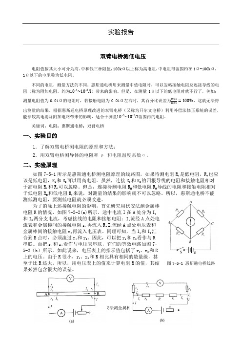
二、实验原理如图7-5-1所示是惠斯通电桥测电阻原理的线路图,如果待测电阻RX 是低电阻,RS也应该是低电阻,R1和R2可以用高电阻。
虽然,连接R1和R2的四根导线的电阻和接触电阻相对于高电阻R1和R2可以忽略。
但是,连接待测电阻RX和低电阻RS导线的电阻和接触电阻相对于低电阻RX 和低电阻RS来说,对测量的结果的影响就不可以忽略。
所以,惠斯通电桥不能测低测电阻,要测低电阻就必须改进。
为了消除上述接触电阻的影响,首先研究用伏安法测金属棒电阻R的情况,如图7-5-2(a)所示。
途中电流I在A处分为I1和I2两分支电流,考虑接线的电阻和接触电阻:I1流经A点处电流表和金属棒间的接触电阻r1再流入R;I2流经A点处电压表和金属棒间的接触电阻r3再流入电压表。
同理可知,当I1和I2汇合到B点时,必须流过r4和r2。
因此,可以把r1和r2看作与R串联。
而把r3和r4看作与电压表串联,它们的等效电路如图7-5-2(b)所示。
如此说来,电压表上的指示值包括了r1、r2和R上的电压。
低电压报警电路
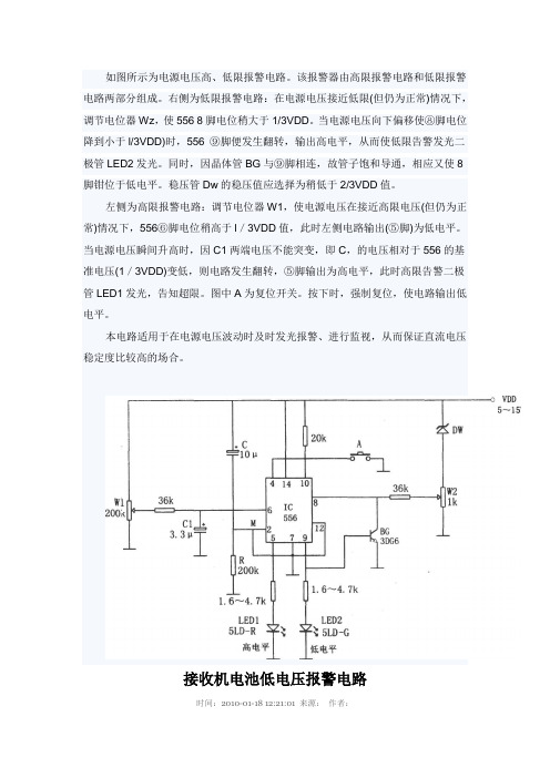
如图所示为电源电压高、低限报警电路。
该报警器由高限报警电路和低限报警电路两部分组成。
右侧为低限报警电路:在电源电压接近低限(但仍为正常)情况下,调节电位器Wz,使556 8脚电位稍大于1/3VDD。
当电源电压向下偏移使⑧脚电位降到小于l/3VDD)时,556 ⑨脚便发生翻转,输出高电平,从而使低限告警发光二极管LED2发光。
同时,因晶体管BG与⑨脚相连,故管子饱和导通,相应又使8脚钳位于低电平。
稳压管Dw的稳压值应选择为稍低于2/3VDD值。
左侧为高限报警电路:调节电位器W1,使电源电压在接近高限电压(但仍为正常)情况下,556⑥脚电位稍高于l/3VDD值,此时左侧电路输出(⑤脚)为低电平。
当电源电压瞬间升高时,因C1两端电压不能突变,即C,的电压相对于556的基准电压(1/3VDD)变低,则电路发生翻转,⑤脚输出为高电平,此时高限告警二极管LED1发光,告知超限。
图中A为复位开关。
按下时,强制复位,使电路输出低电平。
本电路适用于在电源电压波动时及时发光报警、进行监视,从而保证直流电压稳定度比较高的场合。
接收机电池低电压报警电路时间:2010-01-18 12:21:01 来源:作者:接收机电池低电压报警电路--Receiver Battery Low Voltage AlarmHere is another equally cool low voltage alarm circuit for your glider receiver battery that I've shamelessly stolen from George Steiner's book "A to Z--Radio Control Electronic Journal" (see below). I've modified it to use with small battery packs in R/C gliders. This design has a trigger voltage at about 4.3 volts, and it draws 1mA or less when quiet and about 4mA when buzzing. This can be constructed from parts fromt Radio Shack, though you may need to order a few through them.The voltage of a receiver system is punctuated by low-voltage spikes every time the servo motors spin up, since the servos draw more than the battery can deliver. With large receiver battery packs, this is not as much of an issue, and it may not be noticeable. However with 270mA and smaller battery packs, particularly with more than two servos, low voltage alarms can chirp constantly, every time a servo moves. The challenge is to design in a little slack or delay, just enough so that you are not annoyed by constant chirping, but not too much so that the chirps can give you a warning before the battery is completely exhausted. Here, this "hysteresis" is adjusted with the capacitor. For large packs (600mA and above), no capacitor is probably needed, although I've been using a 1uF capacitor on my open class ship with 6 servos and a600mA battery. For 270 mA and two servos, I'd suggest trying a 1uF capacitor. For 150mA or less, a 2.2uF capacitor works well. If you want to know only when the battery has finally reached the trigger voltage, try a 5uF (or 4.7uF) capacitor. The actual type of capacitor is not critical, but tantalum capacitors are physically smaller. If you want to worry about the polarity of the capacitor, the negative side should be directed toward the negative pole of the battery, but at these relatively low voltages compared to the capacitor rating, the polarity probably does not matter.This circuit is set up for a four cell receiver battery pack at a trigger voltage of about 4.3 volts (about 1.1volts/cell). You can adjust R1 (here a 3.3k resistor) to change the trigger voltage of the circuit. For example, for a 5 cell pack, to change the trigger voltage to 5.5 volts, change R1 to 2.2k. For a three cell pack, to change the trigger voltage to 3.3 volts, change R1 to 6.8 k (or use two 3.3k resistors in parallel by soldering a resistor in each hole and twisting together the top leads). Because of slight variability intolerances of the componants, you should check this little device with a variable power source and a voltmeter to confirm its trigger point. Alternately, use your digital voltmeter or expanded scale voltmeter to calibrate its chirp pattern by measuring the voltage of the onboard battery pack intermittently as you fly.Make sure the band on the Zener diode is toward the "+" side (toward R1). Solder a battery connector or servo connector to the board with positive and negative as shown, and plug the connector into an unused slot in your receiver.Radio Shack parts: Here again, you can use smaller rated resistors if you can get them--1/8 watt or less is fine. Tantalum capacitors are physically smaller, but any composition will work.新编555集成电路应用800例000517-转速低限报警器电路电源电压高低限报警器电路更新日期: 2006-5-20 15:16:07作者: 来源:【1楼】bbsniua 鹏积分:998派别:等级:------来自:广西-岑溪你的电阻取值太小,浪费电,这个电路如果不加开关的话估计会把电池耗光为止!红色发光管取1mA够亮了!你的电阻取值太小,浪费电,这个电路如果不加开关的话估计会把电池耗光为止!红色发光管取1mA够亮了!(原文件名:6V时.jpg)引用图片(原文件名:小于6V时.jpg)引用图片______就玩仿真电路!Q:874067119 2009-07-31,16:46:49 资料邮件回复引用回复编辑删除_____就玩仿真电路!Q:874067119 2009-07-31,16:46:49 资料邮件回复引用回复编辑删除___就玩仿真电路!Q:874067119 2009-07-31,16:46:49 资料邮件回复引用回复编辑删除__就玩仿真电路!Q:874067119 2009-07-31,16:46:49 资料邮件回复引用回复编辑删除资料邮件回复引用回复编辑删除料邮件回复引用回复编辑删除回复编辑删除编辑删除2009-07-31,17:15:32 资料邮件回复引用回复编辑删除【2楼】lionliu积分:1760派别:等级:------来自:记号一下 2009-07-31,17:15:32 资料邮件回复引用回复编辑删除记号一下 2009-07-31,17:15:32 资料邮件回复引用回复编辑删除2009-07-31,17:15:32 资料邮件回复引用回复编辑删除2009-07-31,17:15:32 资料邮件回复引用回复编辑删除2009-07-31,17:15:32 资料邮件回复引用回复编辑删除2009-07-31,17:15:32 资料邮件回复引用回复编辑删除2009-07-31,17:15:32 资料邮件回复引用回复编辑删除资料邮件回复引用回复编辑删除【3楼】canback积分:281派别:等级:------来自:乐清-宁波to 1楼分压的电阻取的是小了点,有一个mA,二极管的限流不能改小,因为接的LED是绿色的,和另一个红色的工作指示灯在一个封装里面,太暗了看起来就不像黄色了。
PAM8403

测试条件
THD+N=10%, f=1KHz, RL=4Ω
THD+N=1%, f=1KHz, RL=4Ω
THD+N=10%, f=1KHz, RL=8Ω
THD+N=1%, f=1KHz, RL=8Ω
VDD=5.0V, PO=0.5W, RL=8Ω VDD=3.6V, PO=0.5W, RL=8Ω VDD=5.0V, PO=1W, RL=4Ω VDD=3.6V, PO=1W, RL=4Ω
典型 -3.2 1.6 1.3 2.5 1.3
0.85 1.8 0.9 0.6 1.4 0.72 0.45 0.15 0.11 0.15 0.11 24 -59 -58 -95 80 100 150 90 87 83 16 10 8 3.5 <1 180 140 260 10 1.4 0.7 1.4
符号 VIN
PD
THD+N
GV PSRR
CS SNR Vn Dyn η
IQ IMUTE
ISD Rdson
fsw Vos VIH VIL VIH
参数 电源电压
输出功率
总谐波失真+噪声
增益 电源纹波抑制比
通道隔离度 信号噪声比 输出噪声 动态范围
效率
静态电流 屏敝电流 关断电流 导通电阻 转换频率 输出失调电压 Enable 输入高电压 Enable 输入低电压 MUTE 输入高电压
VDD=5.0V VDD=3.6V VDD=3.0V VDD=5.0V VDD=2.5V to 5.5V IDS=500mA, Vgs=5V
VDD=3V to 5V Vin=0V, VDD=5V
VDD=5.0V VDD=5.0V VDD=5.0V
精工电子 S-8333系列是一种由基准电压电路 说明书

S-8333系列 升压 LCD偏压用 1通道 PWM控制DC/DC控制器© Seiko Instruments Inc., 2004-2010Rev.4.0_00S-8333系列是一种由基准电压电路、振荡电路、误差放大电路、PWM控制电路、低电压误工作防止电路(UVLO)、时钟闩锁式短路保护电路等构成的CMOS升压DC/DC控制器。
最低工作电压为1.8 V,最适合于LCD用电源及低电压工作的移动设备。
由于在ROSC端子部连接了电阻,所以可设定内部的振荡频率最大到1.08 MHz为止。
通过在RDuty端子部连接了电阻,故可控制PWM控制电路的最大占空系数。
在电源投入时的软启动功能由基准电压调整方式、最大占空系数调整方式的2种组合而成,即使由于IC外部的原因而导致FB端子电压保持在不足基准电压的状态下,也可以调整最大占空系数来启动提升输出电压。
通过连接在CC端子部的电阻和电容器的值进行相位补偿,成为可以调整增益值的构成。
因此,使每个应用电路均可针对工作稳定度和过渡响应特性进行合适的设置。
基准电压为1.0 V±1.5%的高精度,通过外接的输出电压设定电阻可以得到任意的输出电压。
另外,通过连接在CSP端子的电容器可设定短路保护电路的延迟时间。
因短路最大占空系数的状态若持续,电容器则被充电,经由一定时间后停止振荡工作。
在电源的电压降低到UVLO检测电压以下后,通过将其提升到UVLO解除电压以上即可解除短路保护功能。
因所设定的输出容量的不同而选择使用陶瓷电容器,或是钽电容器。
该产品可进行各种设定以及选择,加上与采用小型封装的特点相结合,可以成为使用方便的控制器IC。
特点•低电压工作: 1.8 V ~ 6.0 V•振荡频率:利用外接电阻可在280 kHz ~ 1.08 MHz之间设定•最大占空系数:利用外接电阻最大可设定到88.5%47 ~ 88.5%(振荡频率 500 kHz以上)47 ~ 80%(振荡频率不足500 kHz)•基准电压: 1.0 V ± 1.5%•工作温度范围:−40 ~ +85°C•UVLO(低电压误工作防止)功能:检测电压在1.5 V ~ 2.3 V之间,可以0.1 V为进阶单位来选择滞后幅度在0.1 V ~ 0.3 V之间,可以0.1 V为进阶单位来选择•时钟闩锁式短路保护电路:可用外接电容器设定延迟时间•软启动功能:软启动时间可在10 ms, 15 ms, 20 ms的3阶段中进行选择调整方式可采用基准电压调整和最大占空系数调整的2种方式•通过外接设定相位补偿:可利用连接在CC与GND端子之间的电阻和电容器来进行调整•无铅、Sn 100%、无卤素*1*1. 详情请参阅“ 产品型号的构成”。
电压、电流检测电路分析

电压检测电路
电压检测电路 是用来检测室外机供电的交
流电源的。若室外供电电压过低或过高, 则系统会进行保护。如工作电压是否在允 许的范围之内,或着在运行时电压是否出 现异常的波动等。
1、利用电压互感器进行检测的电路 分析
:室外交流220V 电压检测电路原理分析:室外交流220V 电压经电压互感器T01输入,电压互感器便 电压经电压互感器T01输入,电压互感器便 输出一交流低电压,经D08、D09、D10、 输出一交流低电压,经D08、D09、D10、 D11桥式整流,再经R26、R28、C10滤波之 D11桥式整流,再经R26、R28、C10滤波之 后,输出一直流电平,此电平与输入的交 流电成一定的函数关系。
电流检测电路
电流检测电路
电流检测电路是用来检测压机 供电电流的。 供电电流的。保护压机不致在 电流异常时,而损坏压机。 电流异常时,而损坏压机。
1、采用集成运算放大器进行电流检测电路
电流检测电路原理分析
电阻R1、R56采样,信号经LM358放大 电阻R1、R56采样,信号经LM358放大 后送到CPU的第18脚 后送到CPU的第18脚
电 压 检 测 电 路
电压检测电路的电气参数
2、通过直流电利用电阻降压进行检 测的电路分析
.室外交流220V电压通过硅桥整流、
滤波电路滤波后输出到IPM模块的P、 N端,电压检测电路从直流母线的P 端通过电阻进行分压,检测直流电 压进而对交流供电电压进行判断
电路图: 电路图:
电压பைடு நூலகம்测电路
电流检测电路
LM358内部电路 LM358内部电路
电流检测电路
电路的电气参数
LM358输出电压: LM358输出电压:
Analog Devices ADM6823 低电压监控电路数据手册说明书

Low Voltage Supervisory Circuit withWatchdog and Manual Reset in 5-Lead SOT-23 Data Sheet ADM6823 Rev. C Document FeedbackInformation furnished by Analog Devices is believed to be accurate and reliable. However, noresponsibility is assumed by Analog Devices for its use, nor for any infringements of patents or other rights of third parties that may result from its use. Specifications subject to change without notice. No license is granted by implication or otherwise under any patent or patent rights of Analog Devices. T rademarks and registered trademarks are the property of their respective owners. One Technology Way, P.O. Box 9106, Norwood, M A 02062-9106, U.S.A. Tel: 781.329.4700 ©2005–2015 Analog Devices, Inc. All rights reserved. Technical Support FEATURESPrecision low voltage monitoring9 reset threshold options: 1.58 V to 4.63 V 140 ms (minimum) reset timeout Watchdog timer with 1.6 sec timeout Manual reset inputReset output stagePush-pull active-lowLow power consumption: 7 µA Guaranteed reset output valid to V CC = 1 V Power supply glitch immunity Specified from −40°C to +125°C5-lead SOT-23 package APPLICATIONSMicroprocessor systemsComputersControllersIntelligent instrumentsPortable equipment FUNCTIONAL BLOCK DIAGRAM4535-1Figure 1.GENERAL DESCRIPTIONThe ADM6823 is supervisory circuit that monitors power supply voltage levels and code execution integrity in microprocessor-based systems. As well as providing power- on reset signals, an on-chip watchdog timer can reset the microprocessor if it fails to strobe within a preset timeout period. A reset signal can also be asserted by means of an external push-button through a manual reset input. The part is available in nine reset threshold options, ranging from 1.58 V to 4.63 V. The reset and watchdog timeout periods are fixed at 140 ms (minimum) and 1.6 sec (typical), respectively.The ADM6823 is available in a 5-lead SOT-23 package and typically consumes only 7 µA, making it suitable for use in low power, portable applications.ADM6823Data SheetRev. C | Page 2 of 10TABLE OF CONTENTSFeatures .............................................................................................. 1 Applications ....................................................................................... 1 Functional Block Diagram .............................................................. 1 General Description ......................................................................... 1 Revision History ............................................................................... 2 Specifications ..................................................................................... 3 Absolute Maximum Ratings ............................................................ 4 ESD Caution .................................................................................. 4 Pin Configuration and Function Descriptions ............................. 5 Typical Performance Characteristics ............................................. 6 Theory of Operation ........................................................................ 8 Reset Output ..................................................................................8 Manual Reset Input .......................................................................8 Watchdog Input .............................................................................8 Application Information ...................................................................9 Watchdog Input Current ..............................................................9 Negative-Going V CC Transients ...................................................9 Ensuring Reset Valid to V CC = 0 V ..............................................9 Watchdog Software Considerations ............................................9 Outline Dimensions ....................................................................... 10 Ordering Guide .. (10)REVISION HISTORY2/15—Rev. B to Rev. CRemoved ADM6824/ADM6825 (Throughout) (1)Deleted Table 1; Renumbered Sequentially................................... 1 Deleted Figure 3 and Figure 4; Renumbered Sequentially .......... 6 Changes to Figure 4, Figure 5, Figure 7, and Figure 8 ................. 7 Changes to Ordering Guide .......................................................... 12 2/13—Rev. A to Rev. BUpdated Outline Dimensions ...................................................... 11 Changes to Ordering Guide .......................................................... 12 Deleted Automotive Products Section ......................................... 12 9/12—Rev. 0 to Rev. ARemoved ADM6821/ADM6822 (Throughout) ........................... 1 Updated Outline Dimensions ....................................................... 11 Changes to Ordering Guide .......................................................... 11 Added Automotive Products Section........................................... 11 6/05—Revision 0: Initial VersionData Sheet ADM6823 SPECIFICATIONSV CC = 4.5 V to 5.5 V for ADM6823L/ADM6823M; V CC = 2.7 V to 3.6 V for ADM6823T/ADM6823S/ADM6823R; V CC = 2.1 V to 2.75 V for ADM6823Z/ADM6823Y; V CC = 1.53 V to 2.0 V for ADM6823W/ADM6823V; T A = –40°C to +125°C, unless otherwise noted.Rev. C | Page 3 of 10ADM6823Data SheetRev. C | Page 4 of 10ABSOLUTE MAXIMUM RATINGST A = 25°C, unless otherwise noted.Stresses at or above those listed under Absolute Maximum Ratings may cause permanent damage to the product. This is a stress rating only; functional operation of the product at these or any other conditions above those indicated in the operational section of this specification is not implied. Operation beyond the maximum operating conditions for extended periods may affect product reliability.ESD CAUTIONData SheetADM6823Rev. C | Page 5 of 10PIN CONFIGURATION AND FUNCTION DESCRIPTIONSV CCWDI04535-003Figure 2. ADM6823 Pin ConfigurationADM6823Data SheetRev. C | Page 6 of 10TYPICAL PERFORMANCE CHARACTERISTICS04535-006TEMPERATURE (°C)120–40–2020406080100I C C (μA )10.09.57.57.06.59.08.58.06.05.55.04.54.03.5Figure 3. Supply Current vs. Temperature04535-007TEMPERATURE (°C)120–40–2040201008060N O R M A L I Z E D R E S E T T I M E O U T1.201.151.101.050.951.000.900.850.80Figure 4. Normalized RESET Timeout Period vs. Temperature04535-008TEMPERATURE (°C)120–40–2040201008060V C C T O R E S E T D E L A Y (μs )1009080607040502010300Figure 5. V CC to RESET Output Delay vs. Temperature 04535-009TEMPERATURE (°C)120–40–2040201008060N O R M A L I Z E D W A T C H D O G T I M EO U T1.201.151.101.051.000.950.90Figure 6. Normalized Watchdog Timeout Period vs. Temperature04535-010TEMPERATURE (°C)120–40–2040201008060N O R M A L I Z E D R E S E T T H R E S H O L D1.051.031.041.011.020.991.000.970.980.950.96Figure 7. Normalized RESET Threshold vs. Temperature04535-011RESET THRESHOLD OVERDRIVE (mV)100010100M A X I M U M V C C T R A N S I E N T D U R A T I O N (µs )160120140100608020400Figure 8. Maximum V CC Transient Duration vs. RESET Threshold OverdriveData SheetADM6823Rev. C | Page 7 of 1004535-017I SINK (mA)70123456V O UT (V )0.200.150.100.05Figure 9. Voltage Output Low vs. I SINK 04535-018I SOURCE (mA)1.000.20.40.60.8V O U T (V )2.922.902.882.862.842.82Figure 10. Voltage Output High vs. I SOURCEADM6823Data SheetRev. C | Page 8 of 10THEORY OF OPERATIONThe ADM6823 provides microprocessor supply voltage supervision by controlling the microprocessor’s reset input. Code execution errors are avoided during power-up, power-down, and brownout conditions by asserting a reset signalwhen the supply voltage is below a preset threshold. In addition, the ADM6823 allows supply voltage stabilization with a fixed timeout before the reset deasserts after the supply voltage rises above the threshold.Problems with microprocessor code execution can be moni-tored and corrected with a watchdog timer. When watchdog strobe instructions are included in microprocessor code, a watchdog timer detects if the microprocessor code breaks down or becomes stuck in an infinite loop. If this happens, the watchdog timer asserts a reset pulse, which restarts the microprocessor in a known state.If the user detects a problem with the system’s operation, a manual reset input is available to reset the microprocessor by means of an external push-button.RESET OUTPUTThe ADM6823 features an active-low push-pull output. For active-low output, the reset signal is guaranteed to be logic low for V CC down to 1 V .The reset output is asserted when V CC is below the reset threshold (V TH ), when MR is driven low, or when WDI is not serviced within the watchdog timeout period (t WD ). Reset remains asserted for the duration of the reset active timeout period (t RP ) after V CC rises above the reset threshold, after MR transitions from low to high, or after the watchdog timer times out. Figure 11 shows the reset outputs.VV V V CCRESET04535-012Figure 11. Reset Timing DiagramMANUAL RESET INPUTThe ADM6823 features a manual reset input (MR ), which,when driven low, asserts the reset output. When MR transitions from low to high, reset remains asserted for the duration of the reset active timeout period before deasserting. The MR input has a 50 kΩ internal pull-up so that the input is always high when unconnected. An external push-button switch can be connected between MR and ground so that the user can generate a reset. Debounce circuitry is integrated on-chip for this purpose. Noise immunity is provided on the MR input, and fast, negative-going transients of up to 100 ns (typical) are ignored. A 0.1 μF capacitor between MR and ground provides additional noise immunity.WATCHDOG INPUTThe ADM6823 features a watchdog timer, which monitors microprocessor activity. A timer circuit is cleared with every low-to-high or high-to-low logic transition on the watchdog input pin (WDI), which detects pulses as short as 50 ns. If the timer counts through the preset watchdog timeout period (t WD ), reset is asserted. The microprocessor is required to toggle the WDI pin to avoid being reset. Failure of the microprocessor to toggle WDI within the timeout period therefore indicates a code execution error, and the reset pulse generated restarts the microprocessor in a known state.In addition to logic transitions on WDI, the watchdog timer is also cleared by a reset assertion due to an undervoltage condi-tion on V CC or MR being pulled low. When reset is asserted, thewatchdog timer is cleared and does not begin counting again until reset deassserts. The watchdog timer can be disabled by leaving WDI floating or by three-stating the WDI driver.V V V V CCWDIRESET04535-013Figure 12. Watchdog Timing DiagramData SheetADM6823Rev. C | Page 9 of 10APPLICATION INFORMATIONWATCHDOG INPUT CURRENTTo minimize watchdog input current (and minimize overall power consumption), leave WDI low for the majority of the watchdog timeout period. When driven high, WDI can draw as much as 160 µA. Pulsing WDI low-high-low at a low duty cycle reduces the effect of the large input current. When WDI is unconnected, a window comparator disconnects the watch-dog timer from the reset output circuitry so that reset is not asserted when the watchdog timer times out.NEGATIVE-GOING V CC TRANSIENTSTo avoid unnecessary resets caused by fast power supply transients, the ADM6823 is equipped with glitch rejection circuitry. The typical performance characteristic in Figure 8 plots V CC transient duration vs. the transient magnitude. The curves show combinations of transient magnitude and duration for which a reset is not generated for the 4.63 V and 2.93 V reset threshold parts. For example, with the 2.93 V threshold, a transient that goes 100 mV below the threshold and lasts 8 µs typically does not cause a reset, but if the transient is any bigger in magnitude or duration, a reset is generated. An optional 0.1 µF bypass capacitor mounted close to V CC provides additional glitch rejection.ENSURING RESET VALID TO V CC = 0 VThe active-low reset output is guaranteed to be valid for V CC as low as 1 V . However, by using an external resistor with push-pull configured reset outputs, valid outputs for V CC as low as 0 V are possible. For an active-low reset output, a resistor connected between RESET and ground pulls the output low when it is unable to sink current. A large resistance such as 100 kΩ should be used so that it does not overload the reset output when V CC is above 1 V .04535-015Figure 13. Ensuring Reset Valid to V CC = 0 VWATCHDOG SOFTWARE CONSIDERATIONSIn implementing the microprocessor’s watchdog strobe code, quickly switching WDI low-high and then high-low (minimizing WDI high time) is desirable for current consumption reasons. However, a more effective way of using the watchdog function can be considered.A low-high-low WDI pulse within a given subroutine prevents the watchdog from timing out. However, if the subroutine becomes stuck in an infinite loop, the watchdog could not detect this because the subroutine continues to toggle WDI. A more effective coding scheme for detecting this error involves using a slightly longer watchdog timeout. In the program that calls the subroutine, WDI is set high. The subroutine sets WDIlow when it is called. If the program executes without error, WDI is toggled high and low with every loop of the program. If the subroutine enters an infinite loop, WDI is kept low, the watchdog times out, and the microprocessor is reset.04535-014Figure 14. Watchdog Flow Diagram04535-016Figure 15. Typical Application CircuitADM6823Data SheetRev. C | Page 10 of 10OUTLINE DIMENSIONSCOMPLIANT TO JEDEC STANDARDS MO-178-AA1.301.150.150.050.200.08MIN11-01-2010-AFigure 16. 5-Lead Small Outline Transistor Package [SOT-23](RJ-5)Dimensions shown in millimeters04535-019Y: –40°C TO +125°CRJ: 5-LEAD SOT-23NUMBERL: 4.63V M: 4.38V T: 3.08V S: 2.93V R: 2.63V Z: 2.32V Y: 2.19V W: 1.67V V: 1.58VFigure 17. Ordering Code StructureORDERING GUIDEModel 1, 2ResetThreshold (V) ResetTimeout (ms) Temperature Range Quantity Package Description PackageOption BrandingADM6823RYRJZ-RL7 2.63140 −40°C to +125°C3k 5-Lead SO T -23 RJ-5 N0Q ADM6823SYRJZ-RL7 2.93 140 −40°C to +125°C 3k 5-Lead SO T -23 RJ-5 N0Q ADM6823T YRJZ-RL7 3.08 140 −40°C to +125°C 3k 5-Lead SO T -23 RJ-5 N0Q ADM6823VYRJZ-RL7 1.58 140 −40°C to +125°C 3k 5-Lead SO T -23 RJ-5 N0Q ADM6823WYRJZ-RL7 1.67 140 −40°C to +125°C 3k 5-Lead SO T -23 RJ-5 N0Q ADM6823ZYRJZ-RL7 2.32140−40°C to +125°C3k 5-Lead SO T -23 RJ-5 N0Q1 Z = RoHS Compliant Part.2If ordering nonstandard models, complete the ordering code shown in Figure 17 by inserting the reset threshold suffixes. Contact Sales for availability of nonstandard models.©2005–2015 Analog Devices, Inc. All rights reserved. Trademarks and registered trademarks are the property of their respective owners. D04535-0-2/15(C)。
两级cmos 反相器 低电压检测电路

一、概述在集成电路领域中,低电压检测电路一直是一个重要的研究课题。
特别是在现代便携设备如智能手机、平板电脑等电子产品中,由于电池技术的限制,对于电池电压的监测和管理变得尤为重要。
在这个背景下,两级CMOS反相器低电压检测电路作为一种常用的设计方案,受到了广泛的关注。
二、两级CMOS反相器低电压检测电路的原理1. CMOS反相器CMOS(Complementary Metal Oxide Semiconductor)反相器是由P型和N型MOS管共同组成的,具有低功耗、高噪声容限和良好的抗干扰性能等特点。
在低电压检测电路中,CMOS反相器常被用作电压比较器,用于监测输入电压是否低于某一设定阈值。
2. 两级CMOS反相器低电压检测电路两级CMOS反相器低电压检测电路是通过连接两个CMOS反相器来实现对电压的精确监测。
第一个CMOS反相器负责比较输入电压与参考电压,输出一个中间电平的信号;第二个CMOS反相器再将这个中间信号与另一电压比较,最终输出一个二值化的低电压检测结果。
通过使用两级CMOS反相器,可以提高电路的稳定性和准确性。
三、两级CMOS反相器低电压检测电路的设计与优化1. 电路参数的选择在设计两级CMOS反相器低电压检测电路时,需要合理选择CMOS 管的宽度、长度比,以及工作电压等参数。
这些参数的选择直接影响了电路的功耗、速度和噪声等性能指标。
通过对这些参数进行合理调整和优化,可以提高电路的性能表现。
2. 电路的失调和噪声分析由于实际制造工艺的不确定性,CMOS反相器在工作时可能存在一定的失调和噪声。
在设计两级CMOS反相器低电压检测电路时,需要进行相应的失调和噪声分析,并采取相应的校准和抑制措施,以确保电路的可靠性和稳定性。
3. 电路的功耗优化在现代电子产品中,对于功耗的要求越来越高。
在设计两级CMOS反相器低电压检测电路时,需要对电路的功耗进行优化。
可以采取一些低功耗技术比如动态逻辑、电源镜等,来降低整个电路的功耗。
- 1、下载文档前请自行甄别文档内容的完整性,平台不提供额外的编辑、内容补充、找答案等附加服务。
- 2、"仅部分预览"的文档,不可在线预览部分如存在完整性等问题,可反馈申请退款(可完整预览的文档不适用该条件!)。
- 3、如文档侵犯您的权益,请联系客服反馈,我们会尽快为您处理(人工客服工作时间:9:00-18:30)。
HT70xxA-2TinyPower TM Voltage DetectorSelection TableNote:²xx ²stands for output voltages.Both lead free and green compound devices are available.Note the symbol marks below:²#²stands for lead free devices.²+²stands for green compound devices,which are Lead-free and Halogen-free.For the TO92package,the symbol mark will be at the end of the date code.Whereas for the SOT89and SOT23-5,the symbol mask will be located at the end of IC marking.Rev.1.201December 14,2012General DescriptionThe HT70xxA-2series devices area set of three terminal low power voltage detectors implemented in CMOS technology.Each voltage detector in the series detects a particular fixed voltage ranging from 2.2V to 8.2V.The voltage detectors consist of a high-precision and low power consumption standard voltage source as well as acomparator,hysteresis circuit,and an output driver.CMOS technology ensures low power consumption.Although designed primarily as fixed voltage detectors,these devices can be used with external components to detect user specified threshold voltages.Features·Low power consumption ·Low temperature coefficient·High input voltage range (up to 24V)·Output voltage accuracy:tolerance ±1%·Built-in hysteresis characteristic ·TO92,SOT89and SOT23-5packageApplications·Battery checkers ·Level selectors ·Power failure detectors·Microcomputer reset ·Battery memory backup·Non-volatile RAM signal storage protectorsBlock DiagramN Channel Open Drain Output(Normal Open;Active Low)Output Table&CurvePin AssignmentRev.1.202December14,2012Absolute Maximum RatingsSupply Voltage.............................................................................................................................V SS-0.3V to V SS+26V Output Voltage...........................V SS-0.3V to V DD+0.3V Output Current......................................................50mA Storage Temperature............................-50°C to125°C Power Consumption..........................................200mW Operating Temperature...........................-40°C to85°CNote:These are stress ratings only.Stresses exceeding the range specified under²Absolute Maximum Ratings²may cause substantial damage to the device.Functional operation of this device at other conditions beyond those listed in the specification is not implied and prolonged exposure to extreme conditions may affect device reliability.Electrical CharacteristicsHT7022A-2Ta=25°CHT7024A-2Ta=25°CRev.1.203December14,2012HT7033A-2Ta=25°CHT7039A-2Ta=25°CRev.1.204December14,2012HT7050A-2Ta=25°CHT7082A-2Ta=25°CRev.1.205December14,2012Functional DescriptionThe HT70xxA-2series is a set of voltage detectors equipped with a high stability voltage reference which is connected to the negative input of a comparator¾denoted as V REF in the following figure for NMOS output voltage detector.When the voltage drop to the positive input of the comparator(i,e,V B)is higher than V REF,VOUT goes high,M1turns off,and V B is expressed as V BH=V DD´(R B+R C)/(R A+R B+R C).If V DD is decreased so that V B falls to a value less than V REF,the comparator output inverts from high to low,V OUT goes low,V C is high,M1 turns on,RC is bypassed,and V B becomes:V BL=V DD´R B/(R A+R B),which is less than V BH.By so doing,the comparator output will stay low to prevent the circuit from oscillating when V B»V REF.If V DD falls below the minimum operating voltage,the output becomes undefined.When VDD goes from low to V DD´R B/(R A+R B)>V REF,the comparator output and V OUT goes high.The detectable voltage is defined as:V DET(-)=R+R+RR+RA B CB C´V REFThe release voltage is defined as:V DET(+)=R+RRA BB´V REFThe hysteresis width is:V HYS=V DET(+)-V DET(-)The figure demonstrates the NMOS output type withpositive output polarity(V OUT is normally open,activelow).The HT70xxA-2series also supplies options forother output types with active high outputs.Applicationcircuits shown are examples of positive output polarity(normally open,active low)unless otherwise specified.NMOS Output Voltage DetectorRev.1.206December14,2012Application CircuitsRev.1.207December 14,2012Microcomputer Reset CircuitNormally a reset circuit is required to protect the microcomputer system from malfunctions due to power line interruptions.The following examples show how different output configurations perform a reset function in various systems.·NMOS open drain output application for separatepower supply·NMOS open drain output application with R-C delayPower-on Reset CircuitWith several external components,the NMOS open drain type of the HT70xxA-2series can be used to perform a power-on reset function as shown:5V Power Line Monitoring CircuitGenerally,a minimum operating voltage of 4.5V is guaranteed in a 5V power line system.The HT7044A-2is recommended for use as 5V power line monitoring circuit.·5V power line monitor with power-on reset·with5V voltage regulatorChange of Detectable VoltageIf the required voltage is not found in the standard product selection table,it is possible to change it by using external resistance dividers or diodes.·Varying the detectable voltage with a resistance di-viderDetectable voltage=R+RRA BB´V DETHysteresis width=R+RRA BB´V HYS·Varying the detectable voltage with a diode Detectable Voltage=V f1+V f2+V DET Malfunction AnalysisThe following circuit demonstrates the way a circuit analyzes malfunctions by monitoring the variation or spike noise of power supply voltage.Charge Monitoring CircuitThe following circuit shows a charged monitor for protection against battery deterioration by overcharging.When the voltage of the battery is higher than the set detectable voltage,the transistor turns on to bypass the charge current,protecting the battery from overcharging.Rev.1.208December14,2012Level SelectorThe following diagram illustrates a logic level selector.Rev.1.209December14,2012Package InformationNote that the package information provided here is for consultation purposes only.As this information may be updated at regular intervals users are reminded to consult the Holtek website(/english/literature/package.pdf)for the latest version of the package information.3-pin TO92Outline DimensionsRev.1.2010December14,2012Rev.1.2011December14,2012Rev.1.2012December14,2012Product Tape and Reel SpecificationsTO92Reel Dimensions(Unit:mm)Rev.1.2013December14,2012Reel DimensionsSOT89-3Rev.1.2014December14,2012Note:Thickness less than0.38±0.05mm~0.5mmP0Accumulated pitch tolerance:±1mm/20pitches.()Bracketed figures are for consultation onlyRev.1.2015December14,2012SOT89-3Rev.1.2016December14,2012Holtek Semiconductor Inc.(Headquarters)No.3,Creation Rd.II,Science Park,Hsinchu,TaiwanTel:886-3-563-1999Fax:886-3-563-1189Holtek Semiconductor Inc.(Taipei Sales Office)4F-2,No.3-2,YuanQu St.,Nankang Software Park,Taipei115,TaiwanTel:886-2-2655-7070Fax:886-2-2655-7373Fax:886-2-2655-7383(International sales hotline)Holtek Semiconductor(China)Inc.Building No.10,Xinzhu Court,(No.1Headquarters),4Cuizhu Road,Songshan Lake,Dongguan,China523808Tel:86-769-2626-1300Fax:86-769-2626-1311Holtek Semiconductor(USA),Inc.(North America Sales Office)46729Fremont Blvd.,Fremont,CA94538,USATel:1-510-252-9880Fax:1-510-252-9885CopyrightÓ2012by HOLTEK SEMICONDUCTOR INC.The information appearing in this Data Sheet is believed to be accurate at the time of publication.However,Holtek as-sumes no responsibility arising from the use of the specifications described.The applications mentioned herein are used solely for the purpose of illustration and Holtek makes no warranty or representation that such applications will be suitable without further modification,nor recommends the use of its products for application that may present a risk to human life due to malfunction or otherwise.Holtek¢s products are not authorized for use as critical components in life support devices or systems.Holtek reserves the right to alter its products without prior notification.For the most up-to-date information, please visit our web site at .Rev.1.2017December14,2012。