
475手操器说明书
Started2Introduction3 Explosions could result in serious injury or death:Use in an explosive environment must be in accordance with the appropriate local, national, and international standards, codes, and practices. Please review the Reference Information and Product Certifications sections of the 475 Field Communicator User’s Manual for any restrictions associated with safe use. Electrical shock can result in serious injury or death.This device complies with Part 15 of the FCC Rules. Operation is subject to the following two conditions: (1) this device may not cause harmful interference, and (2) this device must accept any interference received, including interference that may cause undesired operation.©2009 Emerson Process Management. All rights reserved.HART is a registered trademark of the HART Communication Foundation.F OUNDATION is a trademark of the Fieldbus Foundation.IrDA is a registered trademark of the Infrared Data Association.Bluetooth is a registered trademark of the Bluetooth SIG, Inc.AMS Suite is a registered trademark of Emerson Electric Co.The Emerson logo is a trademark and service mark of Emerson Electric Co.All other marks are the property of their respective owners. INTRODUCTIONThe 475 Field Communicator Getting Started Guide provides basic guidelines, precautions, and setup information for the 475 Field Communicator. It does not provide in-depth instructions for configuration, diagnostics, maintenance, service, troubleshooting, or Intrinsically Safe (IS) installations. Refer to the 475 Field Communicator User’s Manual on the Resource CD or for more instructions.The 475 Field Communicator supports HART and F OUNDATION fieldbus devices, letting you configure or troubleshoot in the field. Electronic Device Description Language (EDDL) technology enables the 475 Field Communicator to communicate with a variety of devices independent of device manufacturer.4475 Field Communicator Overview 475 FIELD COMMUNICATOR OVERVIEWThe portable 475 Field Communicator includes a color LCD touch screen, a Lithium Ion battery (Power Module), a SH3 processor, memory components, and integral communication and measurement circuitry.When using the 475 Field Communicator to communicate with devices, follow all standards and procedures applicable to the location. Failure to comply may result in equipment damage and/or personal injury. Understand and comply with the sections in this manual.Working in a Hazardous AreaAn Intrinsically Safe (IS-approved) 475 Field Communicator can be used in Zone 0 (FM and CSA only), Zone 1, or Zone 2,for Group IIC, and Class I, Division 1 and Division 2, Groups A, B, C, and D locations.An IS-approved 475 Field Communicator may be connected to loops or segments that are attached to equipment located in Zone 0, Zone 1, Zone 2,for Group IIC; Zone 20, Zone 21, Zone 22,and Class I, Division 1 and Division 2,Groups A, B, C, and D locations.IS-approved 475 Field Communicators are ordered with the KL option and have an additional label on the back of the communicator that lists the approvals.CAUTIONYou can install or remove the Li-Ion battery in a hazardous area environment. You cannot charge the battery in this environment because the power supply/charger (00375-0003-0005) is not IS-approved.Using the Touch Screen and KeypadThe touch screen and keypad let you select menu items and enter text. Tap the screen with the provided stylus or use the up and down arrow keys on the keypad to select a menu item. See Figure1 for the location of the stylus. Double-tap the selected item on the screen or press the right arrow key on the keypad to open a menu item. CAUTIONContact the touch screen using blunt items only, preferably the stylus included with the 475 Field Communicator. Sharp instruments, such as screwdrivers, can damage the touch screen and void the warranty. Repairing the touch screen requires replacement of the entire display assembly, which is possible only at an authorized service center.475 Field Communicator Overview 5Figure 1. 475 Field Communicator HART and F OUNDATION fieldbus Communication Terminals (top)Stylus (in the strap)Bluetooth ® LightIrDA ® Interface (top) Touch Screen DisplayStrap attachment (top)Backlight Key Strap Attachment (side)Enter Key Function Key and Light (for multiple-key combination functionality)Li-Ion Battery (back) and System Card (internal)Strap Attachment (side)Strap Attachment (side)Lights Illuminated by Pressing the Charge Indicator Button (side)Alphanumeric Keypad Tab KeyNavigation Keys (four arrow keys)Strap Attachment (side)Power Key and LightCharge Indicator Button (side)Green Power Supply/Charger Connector on the Battery (side)6475 Field Communicator Overview Battery and Power Supply/ChargerUnderstand and follow the precautions below before using your battery or power supply/charger.•Protect the battery and power supply/charger from moisture, and respect operating and storage temperature limits. See the 475 Field Communicator User’s Manual for temperature limits.•Do not cover the battery or power supply/charger, subject it to prolonged periods of direct sunlight, or place it upon or next to heat-sensitive materials.•Charge the battery with only the power supply/charger. The power supply/charger should not be used with other products. Failure to comply may permanently damage your 475 Field Communicator and void the IS approval and the warranty.•Do not open or modify the battery or power supply/charger. There are nouser-serviceable components or safety elements inside. Opening or modifying them will void the warranty and could cause personal harm.•Follow all applicable regulations when transporting a Li-Ion battery.Charging the BatteryPrior to first portable use, fully charge the Li-Ion battery. The power supply/charger has a green connector to match the connector on the battery. The battery can be charged separately or while attached to the 475 Field Communicator. A full charge takes approximately two to three hours, and the 475 is fully operable when charging. An overcharge condition will not occur if power supply/charger remains connected after charging completes.To maintain performance, charge the battery frequently, preferably after each use. Limit full discharges, if possible. Additional information about maintaining the battery is in the 475 Field Communicator User’s Manual.Power Supply/Charger LightsThree colored lights are on the power supply/charger to indicate the conditions below. Each light displays a different color.Green The battery is fully charged.Flashing green The battery is nearly fully charged.Amber The battery is charging.Flashing amber The power supply/charger is not connected to the475 Field Communicator.Flashing amber and red The remaining charge in the battery is low.Red Charging cannot occur. Contact Technical Support formore information.Installing the System Card and Battery 7Figure 2. Back of the 475 Field CommunicatorINSTALLING THE SYSTEM CARD AND BATTERY1.Remove the protective rubber boot, if attached.2.Place the 475 Field Communicator face down on a level, secure surface.3.With the battery removed, slide the Secure Digital System Card (labeled SystemCard), with the card contacts facing up, into the System Card socket until it clicks. The System Card socket is spring-loaded. See Figure 2 for the System Card socket location. The System Card is not locked into the System Card socket in Figure 2. CAUTION The System Card must be supplied by the 475 Field Communicator manufacturer. Failure to comply will void the IS approval.4.With the 475 Field Communicator still face down, ensure the two battery retainingscrews are loose.5.Align the battery with the sides of 475 Field Communicator, and carefully slide the battery forward until it is secure.CAUTION The connector pins may be damaged if the battery and 475 Field Communicator are improperly aligned.6.Carefully hand tighten the two battery retaining screws. (Do not over tighten, 0.5Nmmaximum torque load.) The tops of the screws should be nearly flush with the 475 Field Communicator. Battery Retaining ScrewsLi-Ion BatteryConnector Pins System Card in the System Card Socket Main Unit LabelStrap AttachmentStrap AttachmentIS Label Location (KL Option)Stand8Removing the Battery and System Card REMOVING THE BATTERY AND SYSTEM CARD1.Remove the protective rubber boot, if attached.2.With the 475 Field Communicator off, place it face down on a level, secure surface.3.Loosen the two battery retaining screws until the top of each screw is above the topof the 475 Field Communicator.4.Slide the battery off the 475 Field Communicator.CAUTIONThe connector pins may be damaged if you pull the battery up rather than slide it off the 475 Field Communicator.5.Push the System Card into the System Card socket until it clicks and releases.6.Slide the System Card out of the System Card socket.STARTING THE 475 FIELD COMMUNICATORBefore startup, ensure the 475 Field Communicator is not damaged, the battery is fully seated, all screws are sufficiently tightened, and the communication terminals are free of dirt and debris.To start the 475 Field Communicator:1.Press and hold the Power key on the keypad until the green light on that key blinks(approximately two seconds). During startup, the 475 Field Communicator notifies you if an upgrade on the System Card needs to be installed. The FieldCommunicator Main Menu displays.e the touch screen or up and down arrow keys to select menu items. To open aselected menu item, double-tap it or use the right arrow key.3.To shut down, press the Power key and tap Shut down from the Power Switchscreen. Tap OK.COMMUNICATING WITH PC APPLICATIONSThe IrDA interface, Bluetooth interface (if licensed), and a supported card reader let the 475 Field Communicator or its System Card communicate with a PC. See Figure 1 for the location of the IrDA interface and the System Card. A card reader can only be used with the Easy Upgrade Utility. See the 475 Field Communicator User’s Manual for more information.Connecting to a Device9 CONNECTING TO A DEVICEUse the provided lead set to connect the 475 Field Communicator to the loop, segment, or device. Three communication terminals for the lead set are on the top of the 475 Field Communicator. Each red terminal is a positive connection for its protocol, and the black terminal is a common terminal shared by both protocols. An access door ensures that only one pair of terminals is exposed at any one time. Several markings indicate which pair of terminals is for which protocol.Only connections to a HART loop and F OUNDATION fieldbus segment are allowed. After the device is connected, double-tap HART Application or F OUNDATION Fieldbus Application from the Field Communicator Main Menu. The appropriate device description is also required. Refer to the latest version of the 475 Field Communicator User’s Manual for details.CAUTIONThe 475 Field Communicator draws approximately 12 mA from the fieldbus segment. Ensure the power supply or barrier on the fieldbus segment has the capacity to provide this additional current. If a fieldbus segment is drawing near the capacity of the segment’s power supply, connecting the 475 Field Communicator may result in loss of communication.TECHNICAL SUPPORTContact your supplier or go to for Technical Support contact information.MAINTENANCE AND REPAIRAny maintenance, repair, or replacement of components not listed below must be performed by specially trained personnel at an authorized service center. You can perform common maintenance procedures listed below:•Cleaning the exterior. Use only a dry, lint-free towel or dampen the towel with a mild soap and water solution.•Charging, removing, and replacing the battery.•Removing and replacing the System Card.•Removing and replacing the stand.•Ensuring that all exterior screws are sufficiently tightened.•Ensuring that the communication terminal recess is free of dirt and debris.10Waste Disposal WASTE DISPOSALProducts with the following label comply with the Waste Electrical and Electronic Equipment (WEEE) directive, 2002/96/EC, which applies to European Union (EU) member states only.The label indicates this product should be recycled and not treated as Array household waste. Customers in EU member states should contact theirEmerson sales representative for information on discarding any part of the475 Field Communicator.For customers in all other world areas, if it is necessary to discard any part of the 475 Field Communicator, follow the waste-disposal regulations applicable in your location. HAZARDOUS SUBSTANCESProducts with the following label are lead-free and comply with the Restriction of the Use of Certain Hazardous Substances in Electrical and Electronic Equipment (RoHS) directive, 2002/95/EC, which applies to EU member states only.The purpose of the directive is to limit the use of lead, cadmium, mercury, Array hexavalent chromium, polybrominated biphenyl (PBB), and polybrominateddiphenyl ether (PBDE) flame retardants in electronic equipment. PRODUCT CERTIFICATIONSOverviewAll 475 Field Communicators have the main unit label (see Figure2). Intrinsically Safe (KL option) 475 Field Communicators also have a label opposite the main unit label. If the 475 Field Communicator does not contain this label (NA option), it is not Intrinsically Safe. See the 475 Field Communicator User’s Manual or for additional approval information.The Industry Canada (IC), Federal Communications Commission (FCC), and Radio and Telecommunications Terminal Equipment (R&TTE) approvals apply to only 475 Field Communicators licensed for Bluetooth.Approved Manufacturing LocationsEmerson Process Management — Leicester, EnglandICThis Class A digital apparatus complies with Canadian ICES-003.Product Certifications11 FCCThis equipment has been tested and found to comply with the limits for a Class A digital device, pursuant to part 15 of the FCC Rules. These limits are designed to provide reasonable protection against harmful interference when the equipment is operated in a commercial environment. This equipment generates, uses, and can radiate radio frequency energy and, if not installed and used in accordance with the instruction manual, may cause harmful interference to radio communications. Operation of this equipment in a residential area is likely to cause harmful interference in which case the user will be required to correct the interference at his own expense. Any modifications made to this device that are not approved by Emerson Process Management may void the authority granted to the user by the FCC to operate this equipment.European Directive Information — CE Compliance Electromagnetic Compatibility (2004/108/EC)Tested to the EN 61326-1 specification.R&TTEThis equipment is in conformity with the Radio and TelecommunicationsTerminal Equipment (R&TTE) Directive 1999/5/EC.ATEX Directive (94/9/EC) (KL option only)Emerson Process Management complies with the ATEX Directive. Applicable standards are EN 60079-0, EN 60079-11, EN 60079-26, and EN 60079-27.Specific ATEX Directive Information is located within this document and the475 Field Communicator User’s Manual.Hazardous Locations Certifications (KL option only)The Intrinsic Safety approvals listed in this section include compliance with the FISCO requirements.North American CertificationsFactory Mutual (FM)Intrinsically Safe for Class I, Division 1, Groups A, B, C, and D and Class I,Zone 0, AEx ia IIC T4 (Ta = 50°C) hazardous locations when connected asindicated in the control drawing 00475-1130 in the 475 Field CommunicatorUser’s Manual. See the control drawing for input and output parameters.Canadian Standards Association (CSA)Intrinsically Safe for use in Class I, Zone 0, Ex ia IIC T4 (Ta = 50°C) hazardous locations when connected as indicated in the control drawing 00475-1130 inthe 475 Field Communicator User’s Manual. See the control drawing for input and output parameters.Product Certifications 12International CertificationIECExCertification No.: BVS 09.0012Ex ia IIC T4 (-10°C ≤ Ta ≤ 50°C)European CertificationsATEX Intrinsic Safety≤ Ta ≤ +50°C)HART Intrinsically Safe Electrical ParametersF OUNDATION fieldbusThe FISCO standard applies to the FM, CSA, IECEx, and ATEX certifications.U i = 30 Volt DCI i = 200 mA P i = 1.0 WattL i = 0C i = 0U 0= 1.9 Volt DCI 0= 32 μAU iIIC = 17.5 Volt DC I iIIC = 215 mA P iIIC = 1.9 WattU iIIB = 17.5 Volt DC I iIIB = 380 mA P iIIB = 5.3 Watt U 0= 1.9 Volt DC I 0= 32 µAU i = 30 Volt DC I i = 380 mA P i = 1.3 WattU 0= 1.9 Volt DC I 0= 32 µA L i = 0C i = 0。
475手操器的使用方法
475手操器的使用方法1、HART475手操器概述◆ HART475手操器支持HART和FOUNDATION现场总线设备,使您可以对设备进行配置、维护或故障排除。
◆ HART475手操器包括一个彩色LCD触摸屏、一块锂离子电池(电源模块)、一个SH3处理器、存储组件、系统卡,以及集成通讯与测量电路。
2、设备互操作性◆ HART475手操器旨在与不同设备生产商的各种HART和FOUNDATION现场总线设备协同运作。
通过由HART通讯基金会和 Fieldbus Foundation支持的电子设备描述语言(EDDL)技术,可实现设备互操作性。
◆ 基本测试是基于所有设备的设备描述上的。
各设备生产商被要求使用HART475手操器完全测试了他们的设备,并取得认证。
若未收到相关认证,当您试图与未测试设备通讯时,就会显示警告信息。
新的设备描述可通过现场通讯器简易升级程序,或在资源CD或DVD中获取。
◆ 电源/充电器指示灯电源/充电器上有三个指示灯,分别表示以下状态。
每个指示灯显示不同的颜色。
颜色状态绿色电池已充满电。
闪烁绿色电池即将充满电。
黄色电池正在充电。
闪烁黄色电源/充电器未连接到HART475现场通讯器。
闪烁黄色和红色电池电量非常低。
红色无法充电。
◆ 电池维护为了保持锂离子电池的性能和寿命,请理解并遵循以下指导原则:①应经常对电池充电,最好是在每次使用完后或夜间进行充电。
如有可能,尽量减少完全放电的次数。
②在高温下频繁使用HART475手操器可导致性能降低。
③长时间储存电池时,请选用等于或接近室温的干燥场所。
在高于室温的环境中长时间储存可导致性能降低。
④如需长时间储存,请确保HART475手操器剩余电量为全部电量的一半或接近一半。
储存过程中,剩余电量将缓慢释放。
请定期对电池充电,以确保剩余电量不会过低。
4、使用HART475手操器触摸屏◆ 您可通过触摸屏和按键区选择菜单项和输入文字。
请使用随附的触笔或键盘区的上下方向键来选择菜单项。
HART475手操器教程
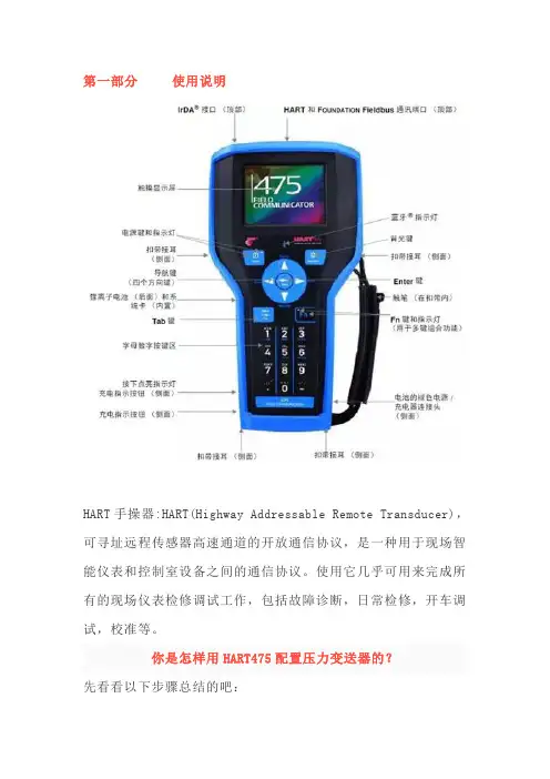
第一部分使用说明HART手操器:HART(Highway Addressable Remote Transducer),可寻址远程传感器高速通道的开放通信协议,是一种用于现场智能仪表和控制室设备之间的通信协议。
使用它几乎可用来完成所有的现场仪表检修调试工作,包括故障诊断,日常检修,开车调试,校准等。
你是怎样用HART475配置压力变送器的?先看看以下步骤总结的吧:1.开机,将手操器与仪表连接,选择HART2.通讯成功以后,选择Online(在线)当出现以下文字时,不要慌张,点YES就行3.具体操作,以川仪(EJA)为例。
改量程改位号、改单位回路测试(打点)调零点PS:在更改完数据后要选“SEND”发送给变送器HART475图形图像都说明了啥现场通讯器屏幕布局常用按钮使用下列按钮,可修改窗口上曲线图和图表的(以艾默生HART475为例)平移,触击按钮,选择图表或曲线图中的一点,拖动此点在窗口中反复地移动。
区域缩放,触击按钮,然后触击并拖动图表中的一点来创建放大的方框。
当您从窗口释放触笔后,图表将放大并适应此区域。
此控件仅可用于条形图表和曲线图。
放大,触击此按钮,从图表中心以固定比率放大。
再次触击,重复此操作。
缩小,触击此按钮,从图表中心以固定比率缩小。
再次触击,重复此操作。
重置,触击按钮,将图表或曲线图返回至原始主屏幕,取消您执行的任何平移或缩放操作。
下拉列表,触击此菜单,在不同的变量中选择,在图表上或曲线图的不同波形中高亮显示。
图形选项图像图像是设备的全屏幕照片。
图像可包含标识和多种图形,如容器。
要查看图像,选择菜单中的图像或绘图标签。
显示全屏幕图像。
要返回菜单视图,按任何键或触击触摸屏。
一些图像具有链接,可以运行方法或查看附加菜单。
如果图像具有链接,将在菜单中的图像或绘图标记旁出现箭头。
当打开图像后,使用向左键返回菜单、或按任意键启动方法或与图像或图纸关联的附加菜单。
如果链接未与图像关联,按任意键返回菜单。
hart475手操器中文说明书
目录第一章简介 (2)第二章基本使用 (3)2.1现场通讯器的基本性能和功能 (3)2.2开机注意事项 (4)2.3键区的使用和说明 (5)第三章在线操作菜单 (6)3.1检测菜单 (6)3.1.1轮询检测 (6)3.1.2按轮询号检测 (7)3.1.3选择设备类型 (7)3.2压力变送器主菜单 (8)3.2.1过程变量 (8)3.2.2组态与测试 (9)3.2.3特征化 (12)3.2.4 校准 (19)3.2.5显示模式 (21)3.2.6通用格式化 (22)3.3电磁流量计主菜单 (23)3.4涡街流量计主菜单 (23)3.5靶式流量计/浮筒液位计主菜单 (23)3.6金转流量计主菜单 (23)3.7通用主菜单 (23)第四章故障排除 (24)4.1故障介绍和排除方法 (24)4.2提示界面 (25)附一 (27)附二 (28)第一章简介感谢您使用本现场通讯器,本通讯器适合HART协议智能变送器的通讯操作,与HART275、HART388、HART375兼容,具有极好的兼容性,可通讯1151, 3051,EJA,ABB及流量方面的HART协议的进口仪表。
完全兼容国产的各种HART协议智能变送器。
该手册介绍了现场通讯器基本的使用、连接和操作方面的内容以及故障的排除和在使用过程中应该注意的事项。
在使用本现场通讯器之前,请阅读该该操作手册,为了更好发挥该产品的最佳性能,在使用或维修本产品之前,请深入掌握相应的内容。
如若设备需要维修,请联系我们公司。
我们将竭尽所能为您服务。
手操器电池(机内)包充电器通讯线缆操作手册250欧姆电阻一.台一块一个一部一条一本一支该设备配备:第二章基本使用2.1现场通讯器的基本性能和功能现场通讯器示图2.2开机注意事项在开机前,请确保以下几点:-该现场通讯器没有物理机械损坏-电池已充满电。
-将现场通讯器连接到回路(如图2-2)-回路中串有250欧姆的电阻图:图2-2启动现场通讯器在启动前请保证该设备已充好电。
475手操器使用方法
475手操器使用方法使用步骤:1.调整握把尺寸:475手操器配有多个不同尺寸的握把,用户首先需要选择合适自己手掌大小的握把。
将握把插入操器的握把插槽中,然后按下插把上方的按钮,将握把固定在设定位置上。
2.起始练习姿势:坐直身体,将475手操器置于桌面或大腿上,便于操作。
调整姿势使手腕和前臂能够舒适地支撑在平面上。
3.握持姿势:将手指自然地放在握把上,并紧握操器。
确保手指尖部分和握把紧密接触,但不要过度用力。
4.关节弯曲训练:开始手部康复训练的第一步是进行关节弯曲练习。
将操器固定在手上后,轻轻向下按压握把,使手指关节弯曲。
保持手指弯曲的位置约5秒钟,然后慢慢松开手指,使其回到初始位置。
每组练习10-15次,并逐渐增加次数和重复次数。
5.关节伸展训练:完成关节弯曲练习后,酌情添加关节伸展训练。
与关节弯曲练习类似,只需要轻轻向上按压握把,使手指关节伸展。
同样地,保持关节伸展的位置约5秒钟,然后慢慢松开手指,使其回到初始位置。
每组练习10-15次,并逐渐增加次数和重复次数。
6.逐渐增加阻力:当手指关节逐渐增强后,可以逐渐增加475手操器的阻力。
通过旋转调节旋钮,将阻力调至适合自己的水平。
适当的阻力可以帮助增加肌肉力量和改善手指关节的灵活性。
7.协调性训练:除了关节弯曲和伸展练习外,还可以进行一些协调性训练,以提高手部协调性。
例如,将操器保持在水平位置,将拇指与其他手指分开并保持约5秒钟,然后放松。
重复此动作10-15次,并逐渐增加次数和重复次数。
同时可以尝试其他类似的协调性训练。
8.每日训练计划:为了获得最佳的康复效果,建议每天进行手部康复训练。
每个练习应持续10-15分钟,以便给手指关节和肌肉提供足够的锻炼机会。
在练习前和后,可以通过轻轻揉捏和按摩手指和手腕来放松肌肉并促进血液循环。
总结:475手操器是一种非常方便和实用的手部康复训练设备,可以帮助改善手指关节的灵活性、力量和协调性。
使用时需要注意调整合适的握把尺寸,掌握正确的握持姿势,并逐渐增加阻力和尝试不同的训练方法。
475 说明书

现 在 有 了 便 利 升 级 功 能,当 新 的 HART 和Ff现 场 总 线 设 备 描 述 文 件 (DDs)发布时, 只需要从互联网直接 下载就可以升级475现场通 讯器了。 随时保持更新,一切尽在您的掌握之 中。
使用 -10°C (14°F ) 到+50°C (122°F ) 0% to 95% RH (无凝结) 从0°C (32°F) 到+50°C (122°F )
充电 10°C (32°F ) 到+40°C (104°F )
带电池储存 -20°C (-4°F ) 到+55°C (131°F )
无电池储存 -20°C (-4°F ) 到+55°C (131°F )
外壳保护级别 IP51(前部)
防撞击 测试通过1米自由落体到水泥表面
便利升级要求
使用 有Internet连接的PC CD Rom驱动器 IrDA口(或红外适配器) 蓝牙接口(或适配器) SD 读卡器(对某些升级需要) WindowsXP(SP2 或SP3)或 Windows Vista 商务版(SP1) 操作系统
键盘 共25键,包括4个动作键,12个数字字母键, tab键,功能键,背光键,电源键,和4个光标 控制(箭头)键
电池 可充电锂离子电池模块
电池运行时间 连续运行-20小时 常规使用-40小时 待机状态-80小时
电池充电器选项 输入电压100-240VAC,50-60Hz 包括电源线,插头有美国,欧洲,和英国选择
对 于HART回 路, 475现 场 通 讯 器 能 确认回路中的DC信号是否正确。
艾默生475手操器操作步骤(压力变送器)

手操器操作步骤
一、开机,将手操器与仪表连接,选择HART(是一种通讯协议)
二、通讯成功以后,选择Online(在线)
三、当出现以下文字时,不要慌张,点YES就行
四、下面以川仪(EJA)变送器为例
1、改量程
2、改位号、改单位此画面内各项含义如下:
1、设备设置
2、当前压力值
3、当前输出电流值
4、量程下限
5、量程上限
在此项按回车或者按键盘
“4”或者按方向键
(下面我会用确认建来代替
以上内容)会出现下图
在此项按下确认键后更改最小值
在此项按下确认键后更改最大值
选择设备设置
项,会出现下图
画面
2、回路测试(打点)
1、过程变量(常已PV缩写
出现)
2、诊断/服务
3、基本设置
4、详细设置
5、浏览
选择基本设置,出现以下画面
常用此两项
1:更改位号
2:更改单位
更改
成功
后会
显示
已改
位号
按键返回上
一层,选择第2
项
出现以下画面,选第2项
3、调零点
1、测试设备
2、回路测试
3、标定、校正
给值,4~20ma信号,(4ma-0;8-25%,12ma-50%,16ma-75%,
20ma-100%),变送器及中控操作站会有相应的显示
打点完成后要选第4项结束,如果直接断开手操器与仪表连接,变送器就会一直显示最后一次给定的值。
所以必须得按步骤退出
返回后选第3项
变送器削减
调零点
注意事项:1、在更改完数据后要选“SEND”发送给变送器。
HART475中文说明书
HART通信器是一种便携式的终端,它与采用HART通信协议的仪表一起使用,对其进行设定,更改和显示,它可监控输入/输出值和自诊断结果。
设定恒定电流的输出和调零。
当系统开动或维持操作时,只要把HART通信器接在4~20mA通信信号线上,就可以使用。
特点:■ 在线监控和通信通信期间,调制信号不会中断4~20mA DC信号■ 与采用HART通信协议的仪表可共用HART通信器能与采用HART通信协议的所有仪表一起使用■ 操作方便大显示屏幕(4行,每行18个字符),采用中文显示,用户看了一目了然,设定和更改方便■ 信息自诊断/保护功能自检查功能格式化密码保护低电压报警显示标准技术规格:装置的技术规格适用仪表:ROSEMOUNT1151 , ROSEMOUNT3051ABB日本富士YOKOGAWA EJA(带HART通信协议)等进口压力变送器DS-1151,DS-3351HK1151 , HK3151等国产智能压力变送器通信信号的连接:专用线缆,长1.1m(3.6ft)通信线:长度:1Km(0.62英里)(0.75~1.25mm2)负载电阻:250~600Ω负载电容:0.22uF以下负载电感:3.3mH以下与电源线的间距:15cm以上(避免平行走线)显示:128*64点阵液晶显示控制:触摸开关(4个方向键,19个功能键,一个电源开关)电源:4支1.2V可充电电池尺寸:180*80*54mm (长*宽*高)重量:700g功能说明基本功能:■ 设定、更改和显示各种参数,HART通信■ 恒定电流输出■ 调零附加功能:■ 格式化保护需要输入密码才能进行格式化■ 电池报警LCD显示的报警信息可提示电池电压偏低■ LCD对比度调节正常工作条件环境温度: -15~55℃存储条件:环境温度:0~50℃附件:■ 通信电缆:壹根,分别带一个弹簧夹。
■ 4只1.5V电池■ 手提包■ 说明书■ 250偶坶电阻EMC认可标准:EMI(辐射)—EN55011:1991hart475手操器 Rosemount罗斯蒙特HART475手操器 产品介绍 hart475手操器通讯器,艾默生过程管理的新型的475现场通讯器,是罗斯蒙特hart375手操器的改良升级型号,它即支持HART 通讯协议,也支持基金会现场总线通讯协议,并具有通用、可靠、便携、本安、易于升级等特点。
475手操器使用方法
如何运用475手操器与总线设备通讯并实现修改变送器参数的功能?一、首先,必须明确FF变送器通讯只有唯一主站。
FF卡件与475如同时连入通讯网则变送器判断主站有多个。
(这就是为何475连接就地变送器端子时会报错;目前成功使用475的案例,操作方法是将卡件端子上FF线缆拆掉,与475表笔连接。
)二、表笔极性:红色表笔连接FF总线电缆橙线,黑色表笔连接FF总线电缆蓝线。
(如图)三、主要使用的功能1、设置变送器测量值零点2、修改现场量与过程量3、设置设备名称与地址4、修改传感器范围与输出范围(量程、单位等)1、通过TB选项改变送器测量值零点(1)475手操器开机,表笔极性连接正确,进入“现场总线”选项,成功扫描到总线设备后,选择需要查看的总线设备。
例如,EJA J0GCF34DP102,双击进入,显示如下界面。
选中“TB”,双击进入该选项。
(2)点击进入左下角“模式”按钮,显示如下界面。
将“√”选中OOS模式,确定。
(3)点击“是”确认修改。
(4)双击进入目录Configuration:\ Primary Value Parament :\Calibration (5)在“Trim Mode”中将“Trim disable”改为“Trim enable”零点校验。
(6)双击进入“Trim PV Zero”(7)手动输入一个零点值,点击“确定”。
即更改了传感器的测量零点。
(8)修改完成后,将“√”选中“自动”模式,点击“确定”后弹出界面询问是否发送,点击“发送”,即可将更改的参数发送到设备。
2、设置现场量与过程量(1)双击进入“AI1”(2)选中双击“Dynamic Variables”,设置现场值和过程值。
(3)双击选中项进入修改即可。
3、设置设备名称与地址(1)双击进入“高级”选项(2)双击“链接主设备组态”(3)将操作类选为“基本”,确定。
(4)弹出警告画面,选择“否”(5)双击进入“细目”可修改设备KKS及地址(6)“物理设备位号”对应KKS码,“地址”对应设备地址(7)手动输入修改量,完成后点击“确定”。
HART475手操器说明书(彩屏款)
目录第一节简介2第二节基本使用2安装电池组2启动和关闭2启动通信器3关闭3基本性能和功能3键区的使用4第三节电气连接方式5建立HART回路连接5查看在线菜单7第一节简介本仪表适合HART协议的智能变送器以及各类HART标准协议的流量仪表的通信操作,与HART275、HART375、HART475兼容,可通信1151,3051,EJA,ABB及其他HART协议的进口仪表,完全兼容国产的各种智能压力变送器以及带有HART协议的智能流量仪表。
第二节基本使用安装电池组1.将现场通信器正面朝下放在平稳的表面上。
2.按住电池后盖开关,将其推向■的一边打开后盖开关,将后盖揭开装进电池,当电池装好后再将后盖开关推向■的一边锁上开关。
(注意在揭开后盖时从缝隙处轻轻揭开,以免损坏后盖)启动和关闭该通信器使用5节5号干电池,使用前请确保:1.该通信器没有损坏2.电池组已安装好3.所有螺丝没有松动4.将通信器连接到回路,参见第三节:建立HART回路连接启动通信器按住开/关键,直到液晶屏点亮,表明装置已经工作。
开/关键位置可参见图2-1。
在启动期间,通信器将自动轮询检测HART回路设备,如果连接正常将显示被连接设备工位号及进入主菜单,您可以进行以下选择:关闭按住“开关”键半秒钟以上,松开按键,关机完成。
键区的使用开关键箭头导航键四个箭头导航键可便于您在菜单栏中移动,选择,进入或退出。
按右箭头导航键()可进入下一级菜单(同Enter 键),在操作界面为“确认”键功能或数据发送功能,对应屏幕显示右侧字符所表示的功能。
按左箭头导航键(口)可返回上一级菜单,在操作界面为“返回”或“取消”键功能,对应屏幕显示左侧字符所表示的功能。
在输入界面基本性能和功能HART 现场通讯接口液晶显示屏字母数字键区图2-1通讯器示意图① Power)用于现场通信器的启动或关闭。
JKL斗STLL开关键四个方向导航键所DawirrtdnlG4lfl r液晶背光B-^rtWFFDK时按下键为删除功能。
475手操器使用教程
475手操器使用教程引言:475(HART)手操器是一种用于操作和配置HART(Highway Addressable Remote Transducer)通讯协议的设备。
本文将详细介绍475手操器的使用方法和步骤,帮助读者快速熟悉和掌握该设备。
一、查找设备1.打开475手操器的电源,待其启动完毕后,进入主界面。
2. 在主界面上方,有一个“Find”按钮,点击该按钮进入设备查找模式。
3.在设备查找模式下,手操器会扫描附近的HART设备,当附近有设备可用时,手操器会显示在屏幕上。
如果屏幕上没有显示任何设备,则表示附近没有可用的HART设备。
4.点击手操器屏幕上显示的设备,即可选中该设备。
二、连接设备1. 选中设备后,点击手操器界面下方的“Connect”按钮,手操器将与所选设备建立连接。
2.当手操器与设备成功建立连接后,手操器界面将显示设备的基本信息,如设备名称、设备型号、设备状态等。
三、读取设备参数1.在设备连接成功后,手操器会自动读取设备的基本参数信息,并显示在手操器界面上。
2. 若要读取更多的设备参数信息,可以点击手操器界面上的“Read”按钮。
3.手操器会根据设备的配置,读取相应的参数信息,并显示在手操器界面上。
四、配置设备参数1.在手操器界面上,可以看到设备的各项参数信息。
2.若要修改一些参数,可以点击该参数所在的位置,并输入新的数值。
确保输入正确后,点击确认按钮进行参数修改。
3.在修改参数后,手操器会自动向设备发送新的参数配置命令,设备会根据手操器的配置进行相应的设置。
五、保存配置1.在参数修改完成后,为确保配置的持久性,需要将配置保存到设备中。
2. 点击手操器界面下方的“Save”按钮,手操器会将当前的配置信息保存到设备中,并显示保存成功的提示信息。
六、退出连接1.在配置完成后,需要断开和设备的连接。
2. 点击手操器界面下方的“Disconnect”按钮,手操器将与设备断开连接。
3.在断开连接后,手操器将返回到主界面,准备进行下一次操作。