
一汽大众蔚领维修手册 1.4- 拆卸和安装发动机
1拆卸和安装发动机⇒ “拆卸发动机” 自6页⇒ “脱开发动机和变速箱” 自16页⇒ “在发动机和变速箱支架上固定发动机” 自18页⇒ “安装发动机” 自19页1.1拆卸发动机所需要的专用工具和维修设备◆撬板 -80 - 200-◆加长件 -2024 A /1-吊钩 -2024 A-◆发动机和变速箱举升装置 -V.A.G 1383 A-◆发动机支架 -T10497-◆车间收集盘-VAS 6208-◆软管卡箍钳-VAS 6362-3Bora NF 2016 ▶, C-TREK 2016 ▶4 缸燃油喷射发动机(1.4L 直喷发动机,涡轮增压器) 10.2016ca r60.co◆锁定销 -T10060 A-◆通用步梯◆护目镜◆防护手套操作步骤提示◆发动机连同变速箱一起向下拆下。
◆所有电缆扎带都应重新装回到相同的位置。
–断开蓄电池 ⇒ 电气设备; 修理组: 27, 起动机,供电,GRA;断开和连接蓄电池接线; 断开蓄电池接线。
–向上翻开并取下保险丝盖板,拧出螺母 -箭头-,将发动机导线从保险丝架上脱开,并将保险丝架从蓄电池上松开,脱开连接插头 -1-。
–拆下蓄电池及其支架 ⇒ 电气设备; 修理组: 27, 起动机,供电,GRA,定速巡航拆卸和安装带有蓄电池监控控制单元 -J367-的接地线。
提示◆接下来需要使用撬板 -80 - 200- 来松开绕线夹。
–拆卸前排水槽盖板 ⇒ 车身外部维修; 修理组: 64, 车身前部; 排水槽; 拆卸和安装排水槽盖板。
Bora NF 2016 ▶, C-TREK 2016 ▶4 缸燃油喷射发动机(1.4L 直喷发动机,涡轮增压器) 10.20163ww.ca r60.co–从发动机控制单元上拔下连接插头 -1-。
–沿 -箭头- 方向向上拔下线束压板,并打开线束扎带 -2-。
–将发动机线束从排水槽中松开并取出。
–脱开发动机电器连接插头 -1-,松开导线扎带 -箭头 a-。
–打开接地线固定夹 -箭头 c-。
–打开线束绕线夹 -箭头 b-,将发动机线束从车身上脱开并置于发动机上。
–打开冷却液膨胀罐的密封盖-箭头-。
–拆卸隔音板 ⇒ 车身外部维修; 修理组: 66, 外部装备;隔音板;装配概述 - 隔音板。
–拆卸左右前轮罩板 ⇒ 车身外部维修; 修理组: 66, 外部装备;车轮罩板;装配概述 - 前车轮罩板。
–车间收集盘 -VAS 6208- 置于下方。
–解锁线束固定夹 -箭头-,将线束从其中脱出,松开软管卡箍-1-,拆下散热器左下方的冷却液软管,排出冷却液。
提示用干净的容器收集排出的冷却液,以便进行废弃处理。
N10-106893Bora NF 2016 ▶, C-TREK 2016 ▶4 缸燃油喷射发动机(1.4L 直喷发动机,涡轮增压器) 10.2016c–松开软管卡箍 -箭头-,拆下增压空气冷却循环回路的散热器右下方的冷却液软管,排出冷却液。
–抬起固定夹 -箭头-,拆卸暖风装置热交换器的冷却液软管。
当心!颠倒已运行过的多楔带,可能会造成损坏。
◆在拆卸多楔带前,先用粉笔或记号笔标记运转方向,便于重新安装。
–逆时针-箭头-方向旋转张紧装置从而松开多楔带轮。
–用锁定销 -T10060 A- 锁定张紧装置。
–取下多楔带。
–脱开空调压缩机调节阀 -N280- 的电气连接插头 -1-。
–拧出空调压缩机的螺栓-箭头-。
当心!制冷剂管路和软管,可能损坏。
◆请勿过度拉伸、弯折或弯曲制冷剂管路和软管。
–取下空调压缩机,用合适的辅助工具将空调压缩机固定到车身上。
Bora NF 2016 ▶, C-TREK 2016 ▶4 缸燃油喷射发动机(1.4L 直喷发动机,涡轮增压器) 10.20163ww.ca r60.co m–松开软管卡箍 -1-,解锁固定卡 -箭头-,从锁支架上拆下空气导管。
–松开软管卡箍 -箭头-,拆卸散热器左上方的冷却液软管。
–松开软管卡箍 -箭头-,拆卸增压空气冷却循环回路的散热器右上方的冷却液软管。
–向后推固定卡-箭头 a- 并向下按压解锁件,以便脱开散热器风扇的电气插头 -1-。
–拧出风扇护罩左右两侧的固定螺栓 -箭头 b-,并向下从散热器中取出风扇护罩。
3Bora NF 2016 ▶, C-TREK 2016 ▶4 缸燃油喷射发动机(1.4L 直喷发动机,涡轮增压器) 10.2016ca r60.co m–拧出螺栓 -2- 并取下螺旋卡箍。
–拧出螺栓 -1- 和螺母-箭头-,绑高尾气催化净化器。
–拧出螺栓-箭头-并取下支架。
提示在下方放置一块抹布,用于吸收溢出的冷却液。
–松开软管卡箍 -1-和-4-,拔下冷却液软管-2-和-3-。
–松开软管卡箍 -1-,将软管从活性炭罐 -2- 上拔下,并从固定夹 -箭头- 中脱出。
当心!可能脏污。
◆对燃油供给系进行作业时遵守清洁规定 ⇒ 4页 。
A26-1125512Bora NF 2016 ▶, C-TREK 2016 ▶4 缸燃油喷射发动机(1.4L 直喷发动机,涡轮增压器) 10.20163ww.ca r60.co m–首先向下压软管接头 -1-,然后按压解锁键 -箭头-。
–在按住解锁键的情况下拔下软管接头。
–沿-箭头-方向松开卡子,拔下真空软管 -1-。
–脱出空气导管 -2- 上的真空软管。
–拧下车身上的接地线-箭头-。
手动变速箱–脱开电气连接插头 -1-、-2-、-3-,沿-箭头-方向脱开护罩,并从起动机起动开关上拧下蓄电池正极线。
–拆下变速箱的换档操纵机构:⇒ 5 档手动变速箱 02J; 修理组: 34, 操纵机构、壳体;修理换档操纵机构; 拆卸和安装换档操纵机构。
–拆卸离合器从动缸:⇒ 5 档手动变速箱 02J; 修理组: 30,离合器;修理离合器操纵机构;拆卸和安装分泵。
双离合器变速箱A10-11565123Bora NF 2016 ▶, C-TREK 2016 ▶4 缸燃油喷射发动机(1.4L 直喷发动机,涡轮增压器) 10.2016ca r60.co m–打开起动机电气连接件护套-2-,脱开电气连接插头 -1-,从起动机磁力开关上拧下蓄电池正极线固定螺母 -箭头- 并取下蓄电池正极线。
–拆卸换档杆拉索,拔下机电控制模块插头并拆下变速箱的所有支架:⇒ 7 双离合变速箱 0CW; 修理组: 34, 控制器、壳体;拆卸和安装变速箱。
–拔下变速箱控制单元插头 -1-,脱开线束固定卡 -箭头-,将导线放置在合适位置。
以下操作适用于所有车辆–旋转大约 2 圈拧出发动机支座的螺栓-箭头-。
–旋转大约 2 圈拧出变速箱支座的螺栓-箭头-。
Bora NF 2016 ▶, C-TREK 2016 ▶4 缸燃油喷射发动机(1.4L 直喷发动机,涡轮增压器) 10.20163ww.ca r60.co m–拧下螺栓 -1- 和 -2-,并取下摆动支承 -3-。
–拧出螺栓 -箭头-,取下右侧传动轴的隔热板。
–拆卸左右两侧前轮 ⇒ 底盘、车桥、转向系; 修理组: 44,车轮、轮胎、车轮定位; 车轮、轮胎; 拆卸和安装轮胎。
–拧出稳定杆两侧连接杆的螺栓 -箭头-。
–拧出主销左右两侧的螺栓 -箭头-。
–脱开横摆臂中的左右两侧主销。
–从变速箱中拆下左右两侧传动轴 ⇒ 底盘、车桥、转向系; 修理组: 40, 前车轮悬挂;维修传动轴;拆卸和安装传动轴。
3Bora NF 2016 ▶, C-TREK 2016 ▶4 缸燃油喷射发动机(1.4L 直喷发动机,涡轮增压器) 10.2016ca r60.co m–如图所示将 夹紧件 -T10497/2- 安装到气缸体壳体肋片上。
–用 螺栓 -T10497/1- 将 发动机支架 -T10497- 安装在气缸体上。
–通过 发动机支架 -T10497- 上的 “B”孔,用螺栓 -1- 拧到 夹紧件 -T10497/2- 上,并以 20 Nm 的力矩拧紧。
–将 连接杆 -T10497/3- 夹紧到 发动机支架 -T10497- 上并用螺栓 -1-以 20 Nm 的力矩拧到发动机上。
–发动机和变速箱举升装置 -V.A.G 1383 A- 插到 发动机支架-T10497- 上并略微抬高发动机/变速箱总成。
提示拧出动力总成支承的螺栓时需要使用通用步梯。
–完全拧出发动机支座的螺栓 -箭头-。
–完全拧出变速箱支座的螺栓 -箭头-。
当心!可能损坏真空管路、电线以及发动机舱。
◆检查发动机、变速箱、副车架和车身之间的所有真空管路或电线是否脱开。
◆降下时,小心地从发动机舱中取出发动机/变速箱总成。
–慢慢降下发动机/变速箱总成,并移出。
VAS 1383A1A10-11334T10497T10497/2T10497/1T10497/3T104971N10-10690Bora NF 2016 ▶, C-TREK 2016 ▶4 缸燃油喷射发动机(1.4L 直喷发动机,涡轮增压器) 10.20163ww.c1.2脱开发动机和变速箱所需要的专用工具和维修设备◆车间起重机-VAS 6100-◆辅助钩-10 - 222 A /12-◆发动机专用塞套件-VAS 6122-吊钩 -T40013-操作步骤●拆下发动机/变速箱总成并固定在发动机支架 -T10497- 上。
–拆下起动机 ⇒ 电气设备; 修理组: 27, 起动机,供电,GRA;起动机;拆卸和安装起动机。
手动变速箱–在变速箱上安装吊钩 -T40013- 并关闭固定件。
–将车间起重机 -VAS 6100- 挂入吊钩 -T40013-。
3Bora NF 2016 ▶, C-TREK 2016 ▶4 缸燃油喷射发动机(1.4L 直喷发动机,涡轮增压器) 10.201616修理组 10 - 拆卸和安装发动机www.ca r60.co m–拧出连接变速箱与发动机的螺栓 -1、2、3、4-。
–从发动机上脱开变速箱双离合变速箱–拉下两个通气孔盖帽 -箭头-。
–用发动机专用塞套件 -VAS 6122- 中清洁密封塞,密封两个排气孔。
–在变速箱上安装辅助钩 -10 - 222 A /12-。
–将车间起重机 -VAS 6100- 挂入辅助钩 -10 - 222 A /12-中。
–拧出连接变速箱与发动机的螺栓 -1–9-。
–从发动机上拔下变速箱。
VAS 610010-222 A/12A10-10829Bora NF 2016 ▶, C-TREK 2016 ▶4 缸燃油喷射发动机(1.4L 直喷发动机,涡轮增压器) 10.201631 拆卸和安装发动机17www.c1.3在发动机和变速箱支架上固定发动机所需要的专用工具和维修设备◆发动机和变速箱支架 -VAS 6095-◆车间起重机 -VAS 6100-操作步骤●脱开发动机和变速箱⇒ 16页 。
–拆卸空气滤清器壳体 ⇒ 197页 。
一汽维修手册
一汽维修手册【原创实用版】目录1.一汽维修手册概述2.手册中的主要内容3.手册的使用方法和注意事项4.一汽维修手册的价值和意义正文一汽维修手册是一本针对一汽品牌汽车的维修工具书,它包含了汽车的各种维修知识和技术指导,为汽车维修人员提供了全面的参考和指导。
下面,我们就来详细了解一下一汽维修手册的主要内容和使用方法。
首先,一汽维修手册概述。
这本手册包含了汽车的整体结构、工作原理和维修技术等方面的知识,覆盖了汽车的发动机、底盘、电气设备等各个系统。
同时,手册中还提供了大量的图片和示意图,以便于读者理解和操作。
其次,手册中的主要内容。
一汽维修手册主要包括以下几部分内容:一是汽车各系统的故障诊断和排除方法,包括故障现象、原因分析和处理方法等;二是汽车各部件的拆卸和安装方法,包括部件的结构、功能和更换步骤等;三是汽车维修常用的工具和设备,以及它们的使用方法和注意事项;四是汽车的日常保养和维护方法,包括保养周期、保养内容和保养技巧等。
再次,手册的使用方法和注意事项。
在使用一汽维修手册时,首先要熟悉手册的结构和内容,了解各章节的作用和关联。
其次,要结合实际情况进行操作,对于故障诊断和维修,要根据车辆的具体情况进行分析和处理。
最后,要注意手册中的一些警告和提示,如在维修过程中要遵循安全操作规程,避免因操作不当造成的人员伤害和设备损坏。
最后,一汽维修手册的价值和意义。
这本手册对于汽车维修人员来说,具有很高的实用价值和参考意义。
它可以帮助维修人员快速准确地诊断和排除汽车故障,提高维修效率和质量;也可以为维修人员提供系统的汽车维修知识,提高其专业技能和素质。
因此,一汽维修手册是一本非常重要的汽车维修工具书。
总之,一汽维修手册是一本内容丰富、实用性强的汽车维修工具书,它为汽车维修人员提供了全面的维修知识和技术指导。
一汽大众蔚领维修手册-发动机列表

⇒ (单位:L)
汽油发动机 1.6
CSRA
4
4
(kW)/rpm
81/5800
(Nm)/rpm
155/3800
10.5:1
Motronic ME 17.5.22
无铅,至少 92 号及以上优质无铅汽油 1)
齿形皮带
1) RON P2 或 P5 优质无铅汽油仅在国排放标准地区提供。
汽油发动机 1.4 CSTA 4 4
96/5000-6000 225/1500-3500
10.5:1 Motronic MED 17.5.25 92 号及以上优质无铅汽油 1)
齿形皮带
ww1 w发.动c机a列r6表0.co1m
3 Bora NF 2016 ▶, C-TREK 2016 ▶
文件盒编号 3.1, 手册 36.1, 版本 10.2016
1 发动机列表
(版本:2016 年 10 月 一汽-大众汽车有限公司)
提示 为了更方便地查找发动机,发动机代码以字母顺序排序。 汽油发动机
发动机: 排量 发动机型号代码 气缸数量 每缸气门数 功率 扭矩 压缩比 喷射装置/点火装置 R02(辛烷值)ቤተ መጻሕፍቲ ባይዱ凸轮轴传动装置
2017一汽大众蔚领—电路图—046 - 1

C-TREK 电路图编号 46 / 110.2016 1.4 升发动机 , CSTA自 2016 年 10 月起ws=白色sw=黑色ro=红色br=褐色gn=绿色bl=蓝色gr=灰色li=淡紫色ge=黄色or=橘黄色rs=粉红色蓄电池, 起动电机, 交流发电机, 电压调节器, 蓄电池监控控制单元 , 保险丝架 A 上的保险丝 1A - 蓄电池B - 起动电机C - 交流发电机C1 - 电压调节器J367 - 蓄电池监控控制单元SA1 - 保险丝架 A 上的保险丝 1T2hh - 2 芯插头连接T4l - 4 芯插头连接T94 - 94 芯插头连接1- 接地带,蓄电池 - 车身507- 螺栓连接(30),在蓄电池保险丝架上652- 变速箱和发动机地线的接地点714- 发动机上右侧接地点B304- 正极连接 8(30),在主导线束中ws=白色sw=黑色ro=红色br=褐色gn=绿色bl=蓝色gr=灰色li=淡紫色ge=黄色or=橘黄色rs=粉红色主继电器, 继电器,用于接线端15 , 保险丝架A 上的保险丝 3 , 保险丝架 A 上的保险丝 6J271 - 主继电器J935 - 转换器盒J940 - 继电器,用于接线端 15SA3 - 保险丝架 A 上的保险丝 3SB5 - 保险丝架 B 上的保险丝 5SA6 - 保险丝架 A 上的保险丝 6SB6 - 保险丝架 B 上的保险丝 6T10z - 10 芯插头连接507- 螺栓连接(30),在蓄电池保险丝架上B298- 正极连接 2(30),在主导线束中B299- 正极连接 3(30),在主导线束中B300- 正极连接 4(30),在主导线束中* - 仅用于带进入及起动许可的汽车ws=白色sw=黑色ro=红色br=褐色gn=绿色bl=蓝色gr=灰色li=淡紫色ge=黄色or=橘黄色rs=粉红色起动机继电器2 , 保险丝架B 上的保险丝2 , 保险丝架A 上的保险丝4J907 - 起动机继电器 2SB2 - 保险丝架 B 上的保险丝 2SA4 - 保险丝架 A 上的保险丝 442- 转向柱旁边的接地点277- 接地连接 3,在车内导线束中347- 接地连接,在车顶导线束中507- 螺栓连接(30),在蓄电池保险丝架上639- 接地点,在左侧 A 柱上A41- 正极连接(50),在仪表板导线束中B660- 连接(接线端 50 诊断),在主导线束中* - 仅用于不带进入及起动许可的汽车ws=白色sw=黑色ro=红色br=褐色gn=绿色bl=蓝色gr=灰色li=淡紫色ge=黄色or=橘黄色rs=粉红色起动机继电器1J623 - 发动机控制单元J906 - 起动机继电器 1T94 - 94 芯插头连接B302- 正极连接 6(30),在主导线束中 B303- 正极连接 7(30),在主导线束中ws=白色sw=黑色ro=红色br=褐色gn=绿色bl=蓝色gr=灰色li=淡紫色ge=黄色or=橘黄色rs=粉红色中部仪表板开关模块, 保险丝架CEX22 - 中部仪表板开关模块E693 - 起动/停止模式按钮SC - 保险丝架 CSC19 - 保险丝架 C 上的保险丝 19SC21 - 保险丝架 C 上的保险丝 21SC22 - 保险丝架 C 上的保险丝 22SC23 - 保险丝架 C 上的保险丝 23SC24 - 保险丝架 C 上的保险丝 24SC25 - 保险丝架 C 上的保险丝 25SC26 - 保险丝架 C 上的保险丝 26T10v - 10 芯插头连接T14a - 14 芯插头连接238- 接地连接 1,在车内导线束中A19- 连接(58d),在仪表板导线束中 B275- 正极连接(87),在主导线束中* - 仅用于带自动起停系统的汽车ws=白色sw=黑色ro=红色br=褐色gn=绿色bl=蓝色gr=灰色li=淡紫色ge=黄色or=橘黄色rs=粉红色保险丝架CD9 - 电子点火开关R - 收音机SC - 保险丝架 CSC1 - 保险丝架 C 上的保险丝 1SC2 - 保险丝架 C 上的保险丝 2SC5 - 保险丝架 C 上的保险丝 5SC14 - 保险丝架 C 上的保险丝 14SC27 - 保险丝架 C 上的保险丝 27SC29 - 保险丝架 C 上的保险丝 29SC45 - 保险丝架 C 上的保险丝 45T7a - 7 芯插头连接B163- 正极连接 1(15),在车内导线束中 B315- 正极连接 1(30a),在主导线束中 B492- 正极连接 3(15),在车内导线束中* - 见收音机装置所适用的电路图*2 - 仅用于不带进入及起动许可的汽车*3 - 导线颜色取决于装备ws=白色sw=黑色ro=红色br=褐色gn=绿色bl=蓝色gr=灰色li=淡紫色ge=黄色or=橘黄色rs=粉红色变压器, 发动机控制单元A19 - 变压器J623 - 发动机控制单元T12l - 12 芯插头连接T94 - 94 芯插头连接131- 接地连接 2,在发动机舱导线束中255- 接地连接 1,在收音机导线束中608- 排水槽内中部的接地点638- 右 A 柱上的接地点B149- 正极连接 2(15a),在车内导线束中B246- 正极连接(30a,稳态),在车内导线束中 D78- 正极连接 1(30a),在发动机舱导线束中ws=白色sw=黑色ro=红色br=褐色gn=绿色bl=蓝色gr=灰色li=淡紫色ge=黄色or=橘黄色rs=粉红色发动机控制单元, 带功率输出级的点火线圈1 , 带功率输出级的点火线圈 2 , 带功率输出级的点火线圈 3 , 带功率输出级的点火线圈 4 , 火花塞插头 , 火花塞J623 - 发动机控制单元N70 - 带功率输出级的点火线圈 1N127 - 带功率输出级的点火线圈 2N291 - 带功率输出级的点火线圈 3N292 - 带功率输出级的点火线圈 4P - 火花塞插头Q - 火花塞T14a - 14 芯插头连接T60 - 60 芯插头连接15- 气缸盖上的接地点306- 接地连接(点火线圈),在发动机预接线导线束中840- 接地连接(发动机接地),在发动机预接线导线束中D25- 正极连接(15),在发动机预接线导线束中ws=白色sw=黑色ro=红色br=褐色gn=绿色bl=蓝色gr=灰色li=淡紫色ge=黄色or=橘黄色rs=粉红色高压传感器, 电磁离合器继电器, 发动机控制单元, 散热器风扇 , 右侧散热器风扇 , 散热器风扇G65 - 高压传感器J44 - 电磁离合器继电器J623 - 发动机控制单元N25 - 空调器电磁离合器T2ay - 2 芯插头连接T2bg - 2 芯插头连接T3a - 3 芯插头连接T4b - 4 芯插头连接T4c - 4 芯插头连接T14a - 14 芯插头连接T94 - 94 芯插头连接V7 - 散热器风扇V35 - 右侧散热器风扇VX57 - 散热器风扇124- 接地连接,在发动机舱右侧导线束中655- 左侧大灯上的接地点656- 右侧大灯上的接地点B3- 连接(右侧转向信号灯),在转向柱开关导线束中D182- 连接 3(87a),在发动机舱导线束中ws=白色sw=黑色ro=红色br=褐色gn=绿色bl=蓝色gr=灰色li=淡紫色ge=黄色or=橘黄色rs=粉红色节气门控制单元, 散热器出口处的冷却液温度传感器, 发动机控制单元GX3 - 节气门控制单元G83 - 散热器出口处的冷却液温度传感器J623 - 发动机控制单元T6x - 6 芯插头连接T60 - 60 芯插头连接T94 - 94 芯插头连接D181- 连接 2(87a),在发动机舱导线束中ws=白色sw=黑色ro=红色br=褐色gn=绿色bl=蓝色gr=灰色li=淡紫色ge=黄色or=橘黄色rs=粉红色机油压力开关, 发动机温度传感器, 发动机转速传感器, 增压压力传感器 , 进气温度传感器 2 , 发动机控制单元F22 - 机油压力开关G27 - 发动机温度传感器G28 - 发动机转速传感器G31 - 增压压力传感器G299 - 进气温度传感器 2J623 - 发动机控制单元T1a - 1 芯插头连接T7a - 7 芯插头连接T60 - 60 芯插头连接209- 接地连接 6,在发动机舱导线束中D236- 连接 5(5V),在发动机预接线导线束中* - 截面积视装备而定ws=白色sw=黑色ro=红色br=褐色gn=绿色bl=蓝色gr=灰色li=淡紫色ge=黄色or=橘黄色rs=粉红色霍尔传感器, 爆震传感器1 , 制动助力压力传感器, 发动机控制单元G40 - 霍尔传感器G61 - 爆震传感器 1G294 - 制动助力压力传感器J623 - 发动机控制单元T3d - 3 芯插头连接T60 - 60 芯插头连接T94 - 94 芯插头连接85- 接地连接 1,在发动机舱导线束中221- 接地连接(发动机接地),在发动机导线束中D154- 正极连接 3(15),在发动机舱导线束中* - 仅用于带手动变速箱的汽车ws=白色sw=黑色ro=红色br=褐色gn=绿色bl=蓝色gr=灰色li=淡紫色ge=黄色or=橘黄色rs=粉红色进气温度传感器, 进气歧管压力传感器, 霍尔传感器2 , 燃油压力传感器 , 发动机控制单元G42 - 进气温度传感器G71 - 进气歧管压力传感器G163 - 霍尔传感器 2G247 - 燃油压力传感器J623 - 发动机控制单元T3 - 3 芯插头连接T60 - 60 芯插头连接132- 接地连接 3,在发动机舱导线束中D240- 连接 9(5V),在发动机预接线导线束中ws=白色sw=黑色ro=红色br=褐色gn=绿色bl=蓝色gr=灰色li=淡紫色ge=黄色or=橘黄色rs=粉红色发动机控制单元, 气缸1 喷油嘴, 气缸2 喷油嘴, 气缸3 喷油嘴 , 气缸 4 喷油嘴J623 - 发动机控制单元N30 - 气缸 1 喷油嘴N31 - 气缸 2 喷油嘴N32 - 气缸 3 喷油嘴N33 - 气缸 4 喷油嘴T60 - 60 芯插头连接T94 - 94 芯插头连接ws=白色sw=黑色ro=红色br=褐色gn=绿色bl=蓝色gr=灰色li=淡紫色ge=黄色or=橘黄色rs=粉红色发动机控制单元, 增压压力限制电磁阀, 活性炭罐电磁阀1 , 凸轮轴调节阀 1 , 排气门凸轮轴调节阀 1 , 机油压力调节阀J623 - 发动机控制单元N75 - 增压压力限制电磁阀N80 - 活性炭罐电磁阀 1N205 - 凸轮轴调节阀 1N318 - 排气门凸轮轴调节阀 1N428 - 机油压力调节阀T14a - 14 芯插头连接T60 - 60 芯插头连接D106- 连接 4,在发动机舱导线束中D141- 连接(5V),在发动机前部导线束中* - 仅用于带手动变速箱的汽车*2 - 仅用于带自动变速箱的汽车ws=白色sw=黑色ro=红色br=褐色gn=绿色bl=蓝色gr=灰色li=淡紫色ge=黄色or=橘黄色rs=粉红色燃油表传感器, 预供给燃油泵, 燃油泵控制单元, 发动机控制单元G - 燃油表传感器G6 - 预供给燃油泵J538 - 燃油泵控制单元J623 - 发动机控制单元T5a - 5 芯插头连接T10n - 10 芯插头连接T94 - 94 芯插头连接87- 接地连接 2,在后部导线束中197- 接地连接 4,在后部导线束中687- 接地点 1,在中央通道上ws=白色sw=黑色ro=红色br=褐色gn=绿色bl=蓝色gr=灰色li=淡紫色ge=黄色or=橘黄色rs=粉红色尾气催化净化器后的氧传感器1 , 尾气催化净化器前的氧传感器 1 , 发动机控制单元 , 燃油定量阀GX7 - 尾气催化净化器后的氧传感器 1GX10 - 尾气催化净化器前的氧传感器 1J623 - 发动机控制单元N290 - 燃油定量阀T4c - 4 芯插头连接T4d - 4 芯插头连接T60 - 60 芯插头连接T94 - 94 芯插头连接H1- 正极连接,在氧传感器导线束中ws=白色sw=黑色ro=红色br=褐色gn=绿色bl=蓝色gr=灰色li=淡紫色ge=黄色or=橘黄色rs=粉红色制动信号灯开关, 制动踏板开关, 离合器位置传感器, 发动机控制单元F - 制动信号灯开关F47 - 制动踏板开关G476 - 离合器位置传感器J623 - 发动机控制单元T4f - 4 芯插头连接T5k - 5 芯插头连接T94 - 94 芯插头连接82- 接地连接 1,在左前导线束中108- 接地连接 2,在左前导线束中655- 左侧大灯上的接地点B335- 连接 1(54),在主导线束中B633- 连接(制动踏板开关),在主导线束中D52- 正极连接(15a),在发动机舱导线束中U6- 连接 2,在自动变速箱导线束中* - 仅用于带手动变速箱的汽车ws=白色sw=黑色ro=红色br=褐色gn=绿色bl=蓝色gr=灰色li=淡紫色ge=黄色or=橘黄色rs=粉红色油门踏板模块, 变速箱空档位置传感器, 发动机控制单元, 循环泵GX2 - 油门踏板模块G701 - 变速箱空档位置传感器J623 - 发动机控制单元T3 - 3 芯插头连接T6h - 6 芯插头连接T60 - 60 芯插头连接T94 - 94 芯插头连接V55 - 循环泵* - 仅用于带手动变速箱的汽车ws=白色sw=黑色ro=红色br=褐色gn=绿色bl=蓝色gr=灰色li=淡紫色ge=黄色or=橘黄色rs=粉红色转向柱组合开关, 车载电网控制单元E595 - 转向柱组合开关J519 - 车载电网控制单元J935 - 转换器盒T10z - 10 芯插头连接T16j - 16 芯插头连接T73a - 73 芯插头连接B239- 正极连接 1(50),在车内导线束中 B441- 连接(GRA),在主导线束中* - 仅用于带进入及起动许可的汽车*2 - 仅用于不带进入及起动许可的汽车ws=白色sw=黑色ro=红色br=褐色gn=绿色bl=蓝色gr=灰色li=淡紫色ge=黄色or=橘黄色rs=粉红色车载电网控制单元, 诊断接口J519 - 车载电网控制单元J935 - 转换器盒T10z - 10 芯插头连接T16 - 16 芯插头连接T73 - 73 芯插头连接T73a - 73 芯插头连接U31 - 诊断接口278- 接地连接 4,在车内导线束中B713- 连接 1(诊断 CAN 总线,High),在主导线束中 B714- 连接 1(诊断 CAN 总线,Low),在主导线束中 D218- 连接 1(LIN 总线),在发动机舱导线束中ws=白色sw=黑色ro=红色br=褐色gn=绿色bl=蓝色gr=灰色li=淡紫色ge=黄色or=橘黄色rs=粉红色车载电网控制单元J519 - 车载电网控制单元T73 - 73 芯插头连接T73a - 73 芯插头连接* - 仅用于带有辅助照明灯的汽车ws=白色sw=黑色ro=红色br=褐色gn=绿色bl=蓝色gr=灰色li=淡紫色ge=黄色or=橘黄色rs=粉红色机油压力降低开关, 冷却液不足显示传感器, 组合仪表中的控制单元F378 - 机油压力降低开关G32 - 冷却液不足显示传感器J119 - 多功能显示器J285 - 组合仪表中的控制单元K3 - 机油压力指示灯K28 - 冷却液温度和冷却液不足显示指示灯K132 - 电子油门故障信号灯T1g - 1 芯插头连接T2s - 2 芯插头连接T14a - 14 芯插头连接T32 - 32 芯插头连接B452- 连接 3(PDC),在主导线束中ws=白色sw=黑色ro=红色br=褐色gn=绿色bl=蓝色gr=灰色li=淡紫色ge=黄色or=橘黄色rs=粉红色组合仪表中的控制单元G1 - 燃油表G5 - 转速表G21 - 车速表H3 - 警报蜂鸣器和警报音J285 - 组合仪表中的控制单元K2 - 发电机指示灯K31 - GRA 指示灯K83 - 废气警告灯K105 - 燃油表指示灯T32 - 32 芯插头连接A178- 连接(信息娱乐 CAN 总线,High),在仪表板导线束中 A179- 连接(信息娱乐 CAN 总线,Low),在仪表板导线束中 B383- 连接 1(驱动 CAN 总线,High),在主导线束中B390- 连接 1(驱动 CAN 总线,Low),在主导线束中* - 仅用于不带辅助照明灯的汽车*2 - 仅用于不带多功能方向盘的汽车*3 - 仅用于带有辅助照明灯的汽车。
发动机气缸盖及正时链拆卸与安装

发动机气缸盖及正时链拆卸与安装发动机气缸盖及正时链拆卸与安装操作步骤:第一章:准备工作1·1 确保车辆停在平坦且稳定的地面上,切断发动机的点火系统。
1·2 引擎冷却至室温后开始操作,以防烫伤。
1·3 准备好所需的工具和材料,包括扳手、螺丝刀、橡胶垫、拆卸工具等。
第二章:拆卸前的注意事项2·1 仔细阅读车辆制造商提供的维修手册,了解具体的操作步骤和注意事项。
2·2 确定拆卸顺序,并按照顺序进行操作,以避免损坏其他部件。
2·3 尽量保持工作环境清洁,防止杂质进入发动机内部。
第三章:拆卸发动机气缸盖3·1 拧松发动机气缸盖上的螺栓,并按照制造商的规定顺序进行。
3·2 清洁气缸盖周围的表面,以确保拆卸过程中不会有杂质进入。
3·3 用拆卸工具轻轻撬开气缸盖,以免损坏密封垫。
第四章:拆卸发动机正时链4·1 定位并标记正时链上的关键部位,如张紧器、齿轮等。
4·2 用专用工具解除正时链的张紧器,然后取下链条。
4·3 检查链条的磨损情况,如有损坏或松动,应及时更换。
第五章:安装发动机气缸盖和正时链5·1 清洁气缸盖和发动机缸体上的残留物,并确保表面光滑。
5·2 按照制造商的指示正确安装气缸盖,并依次拧紧螺栓。
5·3 安装正时链时,请确保链条正确对齐张紧器和齿轮等部件。
5·4 使用专用工具调整正时链的张紧程度,确保链条紧固。
第六章:测试和调整6·1 安装好发动机气缸盖和正时链后,“转动发动机几圈以确保正时链没有松动和卡住的问题。
6·2 检查发动机的运行状况,确保气缸盖和正时链安装正确,无异常声音和震动。
附件:本文件无附带内容,请根据实际情况自行准备相关附件。
法律名词及注释:1·发动机气缸盖:位于发动机缸体上方,用于封闭气缸和气缸盖之间的空间,并提供气缸内部的密封功能。
发动机气缸盖及正时链拆卸与安装

发动机气缸盖及正时链拆卸与安装
发动机气缸盖及正时链拆卸与安装操作指南:
1:准备工作
1.1 确保发动机冷却后,切断电源,拆掉负极电缆。
1.2 若发动机已经运行,请等待至少30分钟以使其冷却。
1.3 将车辆停放在平坦的地面上,并稳固好车辆位置。
2:拆卸气缸盖
2.1 拆卸进气管和进气歧管。
2.2 拆卸所有连线和传感器,注意标记每个部件,以便安装时
能准确连接。
2.3 拆卸火花塞线和火花塞,确保标记正确以免错配。
2.4 拆卸进气门盖,谨慎移除以保护气门。
3:拆卸正时链
3.1 拆卸正时链罩盖,注意标记好拆下的零件,以便正确装配。
3.2 使用专用工具松开正时链张紧器,取下链条。
4:安装正时链
4.1 将新的正时链正确安装在曲轴齿轮和凸轮轴齿轮上,确保链条的紧绷。
4.2 使用专用工具将正时链张紧器固定在正确的位置上,确保链条的合适张力。
4.3 安装正时链罩盖,注意安装位置和正确的紧固螺栓。
4.4 根据制造商的建议,检查和调整正时链的张力。
5:安装气缸盖
5.1 清洁气缸盖和气缸垫面,确保没有杂物和污垢。
5.2 安装气缸盖,根据制造商的扭矩规范依次紧固螺栓。
5.3 安装进气门盖和连接线路,确保连接牢固。
5.4 安装火花塞线和火花塞,确保正确连接。
6:完成工作
6.1 检查所有连接和螺栓是否牢固。
6.2 重新连接负极电缆。
6.3 启动发动机并检查是否有异常噪音或漏油。
附件:
本文档未涉及附件。
法律名词及注释:无。
大众1.4TSI全面拆解
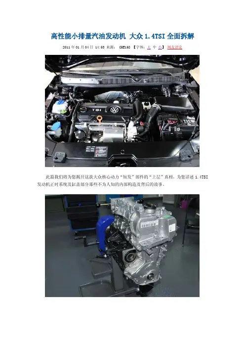
高性能小排量汽油发动机大众1.4TSI全面拆解2011年01月04日 14:53 来源: CHE168 【字体:大中小】网友评论此篇我们将为您揭开这款大众核心动力“短发”部件的“上层”真相,为您详述1.4TSI 发动机正时系统及缸盖部分那些不为人知的内部构造及背后的故事。
注释:发动机“短发”部分:组成基础发动机的缸体、缸盖、曲轴、连杆、凸轮轴等核心零部件;发动机“长发”部分:装配在基础发动机上最后形成完整引擎的外挂零部件。
● 1.4TSI发动机正时系统在1.4TSI发动机“短发”部分的拆解中,对于发动机“正时系统”相关执行部件的“分体”则是首道必行工序,而此道工序为何具备“首要执行”因素?“正时系统”又为何物?在本章进入正式拆解前,让我们率先走进发动机“正时”的原理世界:★何为发动机“正时系统”?“正时系统”是发动机配气机构的重要组成部分,是保障发动机呼吸顺畅的重要因素之一。
其主要通过控制气门开闭的时刻,准确的实现定时开启和关闭相应的进、排气门,使新鲜充量的空气得以及时进入气缸,废气得以及时从气缸排出,保证发动机具有正常、良好的动力输出表现。
正时系统执行元件示意而就目前大多数发动机的正时系统工作过程而言,其主要由曲轴通过链条或者皮带带动凸轮轴运转,通过凸轮工作面的旋转顶压气门挺杆,进而推动气门向气缸内运动,从而实现气门被打开;在凸轮工作面旋转之后,气门会在气门弹簧的作用下回位,从而气门被关闭。
而正是由于正时系统执行部件的运转,与上述发动机“短发”部分自上而下的诸多核心部件都有所关联,因此,在针对核心部件进行拆解前,卸除正时罩壳、正时皮带/链条等“关联”件,则成为首当其冲的必备工序。
★ 1.4TSI发动机正时罩壳:多元集成者正时罩壳的主要功用,除却承担对于发动机侧部正时系统传动件的保护和密封作用外,集成发动机功能能部件也是其职责所在。
1.4TSI的发动机正时罩壳,则将机油滤清器、油气分离器、加油注口集于一身。
大众1.4TSI拆解之发动机附件篇
黄金分割大众1.4TSI拆解之冷却、增压篇“1.4TSI+7速DSG”,一汽-大众这套被形容为“黄金”的动力总成,在国内车市一度掀起了消费者对小排量增压发动机和双离合变速器的热潮,众多厂商也纷纷效仿一汽-大众推出了自己的增压动力和双离合变速器。
但作为这项技术在国内引领者的一汽-大众,似乎只是一直在被追赶,却从未被超越。
近日,我们来到了一汽-大众长春的发动机制造厂,对一汽-大众的“黄金动力”——1.4TSI发动机进行了彻底的拆解和研究。
我们将按照拆解顺序,根据这台发动机的特点和大量网友们对它的疑问,分三篇为大家带来全面详尽且深入浅出的解读。
下面,我们就先一起来看看这台“传说中”的小排量增压发动机,围绕着字母“T(涡轮增压)”究竟都有何过人之处吧。
● 进气冷却系统拆解我们本次拆解的这台1.4TSI是一台刚刚从一汽-大众的生产线上下线的全新发动机,在对这台发动机进行上台架等固定工序后,我们的拆解也正式开始。
首先将进行拆解的部分是这台发动机的独立循环冷却系统。
『刚刚走下生产线的EA111系列1.4TSI发动机』冷却系统示意图,彩色为独立的进气和涡轮循环冷却系统,灰色为发动机内的循环冷却系统(蓝色为低温冷却液,红色为高温冷却液)这款1.4TSI发动机一大特色就是采用了两套独立的冷却系统:一套主要用于发动机自身冷却的发动机冷却系统,这套系统中的水泵通过皮带和曲轴相连接,直接靠发动机动力实现冷却液的循环,也可称为主循环;另一套冷却系统主要用于涡轮增压器和增压空气的冷却,是通过电动冷却液循环泵驱动冷却液实现的独立循环系统,也可称为副循环。
『副循环中冷却液循环泵位置示意图』1.4TSI发动机上的双循环冷却系统也是大众首次采用的发动机冷却方式。
其中独立的冷却液循环泵主要用于给增压系统冷却,包括两个循环通道:一个经过涡轮增压器,为涡轮系统冷却;另一个流经进气歧管内的气液热交换器(冷却器),为增压空气进行冷却。
两套独立冷却系统实现了缸盖和缸体温度的不同,在不同工况下可以根据需要分别对不同的部分进行冷却。
请叙述发动机拆装的顺序及要求
请叙述发动机拆装的顺序及要求
发动机拆装是汽车维修中非常重要的一部分,正确的拆装顺序可以避免损坏发动机部件,保证整个维修过程的顺利进行。
以下是发动机拆装的一般顺序和要求:
1. 准备工作:首先需要将车辆停放在平坦的地面上,并将手刹和换挡杆置于停车位。
然后需要断开电池的负极,以避免电击和系统短路。
2. 拆除配件:拆除发动机罩、散热器、空调压缩机、发电机、水泵、皮带、进气道、排气系统等配件。
拆卸时需要注意每个部件的螺栓位置和大小,避免混淆和损坏。
3. 拆卸发动机:需要先将变速箱与发动机分离,然后卸下发动机支架上的螺栓,最后使用吊装工具将发动机缓缓卸下。
4. 检查发动机部件:在拆卸发动机时,需要对部件进行清洗、检查和更换。
若出现磨损或其他问题,需要及时更换。
5. 安装发动机:将检查过的发动机部件重新安装到发动机上,注意螺栓的位置和大小,尤其是与变速箱的连接处需更为谨慎。
在安装过程中,还需要更换新的密封垫和润滑油。
6. 装配配件:安装完成发动机后,需要将之前拆卸的配件再次安装。
在此过程中,需要确保每个螺栓都已经正确固定并紧密连接。
7. 启动发动机:安装完成后,需要检查所有螺栓的紧固度、车辆的润滑油和冷却液的水平。
最后启动发动机检查其工作状态是否正常,以保证整个工作过程的顺利完成。
总之,在发动机拆装过程中,需要非常小心谨慎,遵循正确的顺序和要求,保证安全和成功完成整个维修过程。
发动机拆装流程
发动机拆装流程
发动机拆装流程
一、设备准备
1、发动机的拆装前,首先应对发动机进行检查,确认机器各部件状况良好,发动机无漏油、磨损或损坏现象,确认拆装工具及部件全部齐全。
2、熟悉发动机的每一个零部件,熟悉发动机拆装手册,以便拆装时快速找到要拆卸的零部件,减少不必要的拆装时间。
3、在拆装时,记录发动机的各个细节状态,以便拆装结束后能够对拆装的状况进行检查,避免存在问题。
二、拆装流程
1、将发动机放置在平滑、安全的工作台上,打开发动机的缸体盖,拆卸缸体上各个部件(发动机拆装手册中应有详细的拆装流程),将拆卸下来的各个零部件放置整洁。
2、拆卸发动机压缩环、缸套、活塞、曲轴、连杆等。
3、拆卸发动机缸体外侧部件,如壳体、热风及进气管、排气管、滤清器、气门、节气门等。
4、拆卸发动机内侧部件,如油室、油泵等。
5、整理出发动机各个零部件,清除零部件内外的污渍,根据发动机拆装手册进行发动机组装(组装发动机时,需要特别注意每个零部件的安装位置和方式,以保证发动机能正常工作)。
三、拆装完毕
1、完成发动机的拆装后,将拆装的零部件放置在特定位置,进行一次简单的检查,确认无误后,可进行安装。
2、安装发动机时,必须按照拆装时的顺序,将发动机的各个零部件安装好,然后依次安装发动机壳体、热风及进气管、排气管、滤清器、气门、节气门等,最后将发动机安装好。
大众1.4TSI维修保养手册英文版
The 1.4l TSI* engine is the world’s first petrol engine with direct petrol injection and dual-charging. Volkswagen is thus laying another milestone in engine development.* The term “TSI” is a protected abbreviation of Volkswagen.S359_002On the following pages, we will introduce you to the design and function of the new 1.4l TSI engine with dual-charging.Introduction . . . . . . . . . . . . . . . . . . . . . . . . . . . . . . . . . . . . . . . . . . . . . . . . . . 4Engine mechanics . . . . . . . . . . . . . . . . . . . . . . . . . . . . . . . . . . . . . . . . . . . . . . 6Poly-V-belt drive . . . . . . . . . . . . . . . . . . . . . . . . . . . . . . . . . . . . . . . . . . . . . . . . . 6Timing chain . . . . . . . . . . . . . . . . . . . . . . . . . . . . . . . . . . . . . . . . . . . . . . . . . . . . 7Cylinder block . . . . . . . . . . . . . . . . . . . . . . . . . . . . . . . . . . . . . . . . . . . . . . . . . . . 8Cylinder head and valve train . . . . . . . . . . . . . . . . . . . . . . . . . . . . . . . . . . . . 10Dual-charging with supercharger and turbocharger . . . . . . . . . . . . . . . . . 11 Crankcase breather and ventilation . . . . . . . . . . . . . . . . . . . . . . . . . . . . . . . 21 Oil system . . . . . . . . . . . . . . . . . . . . . . . . . . . . . . . . . . . . . . . . . . . . . . . . . . . . .22Dual-circuit cooling system . . . . . . . . . . . . . . . . . . . . . . . . . . . . . . . . . . . . . . 24Demand-regulated fuel system . . . . . . . . . . . . . . . . . . . . . . . . . . . . . . . . . . . 26Exhaust system . . . . . . . . . . . . . . . . . . . . . . . . . . . . . . . . . . . . . . . . . . . . . . . . . 27 Engine Management . . . . . . . . . . . . . . . . . . . . . . . . . . . . . . . . . . . . . . . . . . 28System Overview . . . . . . . . . . . . . . . . . . . . . . . . . . . . . . . . . . . . . . . . . . . . . . 28CAN networking . . . . . . . . . . . . . . . . . . . . . . . . . . . . . . . . . . . . . . . . . . . . . . 30Engine Control Unit . . . . . . . . . . . . . . . . . . . . . . . . . . . . . . . . . . . . . . . . . . . . . 31 Sensors . . . . . . . . . . . . . . . . . . . . . . . . . . . . . . . . . . . . . . . . . . . . . . . . . . . . . . . 32Actuators . . . . . . . . . . . . . . . . . . . . . . . . . . . . . . . . . . . . . . . . . . . . . . . . . . . . . . 46Functional Diagram . . . . . . . . . . . . . . . . . . . . . . . . . . . . . . . . . . . . . . . . . . . . . 58Service . . . . . . . . . . . . . . . . . . . . . . . . . . . . . . . . . . . . . . . . . . . . . . . . . . . . . . 60Test Y ourself. . . . . . . . . . . . . . . . . . . . . . . . . . . . . . . . . . . . . . . . . . . . . . . . . . 62ContentsIntroductionThe special concept behind this engine is, above all,the combination of direct petrol injection, dual-charging and downsizing.-Volkswagen used direct petrol injection for the first time in the Lupo FSI model year 2001.-In dual-charging, the engine is charged by amechanical compressor and/or a turbocharger.-Downsizing is replacing a large-capacity engine with a powerplant with smaller displacement and/or fewer cylinders. This reduces the internal frictionand this the fuel consumption without the power ortorque being reduced.Special Technical FeaturesTechnical features●Two output versions delivering 103kW and 125kW ●Bosch Motronic MED 9.5.10●Homogenous mode (Lambda 1)●Double injection catalytic converter heating●Turbocharger with waste gate●Additional mechanical supercharger●Intercooler●Maintenance-free timing chain●Engine cover with vacuum tank for the intakemanifold flap control ●Plastic intake manifold●Continuous inlet camshaft timing adjustment●Grey cast iron cylinder block●Steel crankshaft●Duo-centric oil pump●Dual-circuit cooling system●Fuel system regulated according to requirements ●High-pressure fuel pump with a delivery pressureof up to 150 barS359_003Thanks to this concept, it has greater performance than engines with the same output and also consumes less fuel. It therefore meets customer demands for economic FSI engines with a high level of dynamism.Technical data1.4l/125kW TSI enginerpmNmkWS359_093Torque [Nm]Power [kW]rpmNmkWS359_094Power [kW]Torque [Nm]Torque and power diagramThe different output and torque levels are achieved using software. The engine mechanics are the same in both engines.1.4l/103kW TSI engineTechnical dataEngine code BMYBLGType 4-cylinder in-line engine 4-cylinder in-line engine Displacement 13901390Bore 76.576.5Stroke75.675.6Valves per cylinder 44Compression ratio 10:110:1Maximum output 103 kW at 6,000 rpm 125 kW at 6,000 rpm Maximum torque 220 Nm at 1,500 – 4,000 rpm 240 Nm at 1,750 – 4,500 rpm Engine management Bosch Motronic MED 9.5.10Bosch Motronic MED 9.5.10FuelSuper unleaded RON 95Super Plus at RON 98(Super unleaded at RON 95 with slightly higher consumption and torque reduction in the low rev ranges)Exhaust gas treatment Main catalytic converter,Lambda control Main catalytic converter,Lambda control Emissions standardEU 4EU 4Engine mechanicsAlternator belt pulleyBelt tensionerAir-conditioning compressor belt pulleyAncillary components drive beltCompressor beltpulleyCamshaft beltpulleyCoolant pump pulleyPulley for supercharger magnetic clutch N421Tensioning pulleySuperchargerdrive belt TensioningpulleyPoly-V-belt driveS359_004The 1.4l TSI engine has two poly-V-belts.-The ancillary component drive belt is a six-groove poly-V-belt. It drives the coolant pump, the alternator and the air-conditioning compressor from the camshaft pulley.-The supercharger drive belt is a five-groove poly-V-belt. It drives the compressor via the magnetic clutch pulley when the magnetic clutch is engaged.A tensioning pulley ensures that the ancillary component and supercharger belts are correctly tensioned. The tensioning pulley after the crankshaft pulley also ensures that the poly-V-belt runs correctly around the crankshaft pulley and coolant pump pulley.Hydraulic chain tensioner Tensioning railSprocket for camshaft driveSprocket for driving camshafts and oil pump Oil pump drive toothed chainOil pump sprocketSlide railSpring-loaded chain tensioner Sprocket forinlet camshaft with vaneadjusterOutlet camshaftsprocketS359_005Chain driveBoth the camshafts and also the oil pump are driven by the crankshaft via a maintenance-free timing chain.Camshaft timing adjustmentA load- and engine speed-dependent vane adjuster is used for the continuous inlet camshaft adjustment. The adjustment range is a maximum 40° crank angle.The camshaft adjustment allows:-Very good internal exhaust gas recirculation and -improved torqueband.Oil pump driveThe oil pump is driven by a toothed chain with 8 mm pitch for improved sound.It is tensioned by a spring-loaded chain tensioner.Camshaft driveThe toothed chain drive has been optimised due to the greater loading. The toothed chain has hardened pins and heavy-duty link plates that have been adapted to the chain forces.The toothed chain is tensioned by a hydraulic chain tensioner.S359_006Cylinder liningOuter wallEngine MechanicsCylinder blockAs with the 1.4l/66kW and 1.6l/85kW FSI engines, the cylinder block has a so-called open-deck design. This means that there are no webs between the outer wall and the cylinder lining.This has two advantages:-No air bubbles can form in this area which would lead to ventilation and cooling problems particularly with the dual-circuit cooling system,-When the cylinder head is bolted to the cylinder block, the cylinder liner deformation caused by the decoupling of the cylinder liner and cylinder block is less and more even than with a closed-deck design with webs. This results in lower oil consumption as the piston rings compensate this deformation better.The cylinder block on the 1.4l TSI engine is made from grey cast iron with lamellar graphite. This guaranteessufficient operating safety at the high combustion pressures of the TSI engine. Due to the high strength of a cylinder block made from grey cast iron with lamellar graphite compared with one made from diecast aluminium,the camshaft may be removed.Y ou will find further information on the 1.4l/66kW and 1.6l/85kW FSI engines in self-study programmes 296 “The 1.4l and 1.6l. FSI engine with timing chain” and 334 “The fuel system in FSI engines”.Crankshaft driveCamshaftPiston pinConnecting rodPistonCoated piston skirtS359_007The crankshaft drive consists of the crankshaft, the connecting, the bearing shell, the piston and the piston pin. Several modifications have been made to the crankshaft drive as the forces occurring on the 1.4l TSI engine are considerably higher than with the previous FSI engines.PistonThe pistons are made from diecast aluminium.A combustion chamber recess with a deflector has been worked into the piston base. This leads to a strong swirling of the intake air and thus to a very good mixture formation.The outlet side of the piston is cooled with a piston cooling system. The jets open at 2.0 bar.The friction of the piston package has been reduced by a graphite coating on the piston skirt and a greater skirt-to-wall clearance of 55 µm.The piston pin diameter has been increased from 17 to 19 mm due to the high ignition pressure.CamshaftThe forged crankshaft is made from steel and is stiffer than the cast crankshaft on the 1.4l/66kW FSI engine.Above all, this reduces the noises from the engine.Connecting rodThe connecting rods are fracture-split. Therefore only the same two components fit together, they are cheap to produce and good positive engagement is formed.Engine MechanicsS359_097High-pressure fuel pumpRoller tappetPump camCamshaft caseInlet camshaftThe cylinder head is the same as on the 1.4l/66kW FSI engine except for a few modifications.Several changes have been made to the valve train due to the greater loads and exhaust gas temperatures.●Due to the higher loads, the outlet valves arereinforced on the valve seats and the valve springs are heat-treated.●Due to the higher exhaust gas temperatures, the outlet valves are filled with sodium for better heat transfer. This reduces the temperature at the outlet valves by approx. 100°C.Camshaft caseThe camshafts, which are mounted on three bearings, are inserted into the camshaft case. Their axial play is limited by the cover and the camshaft case.The high-pressure fuel pump is bolted to the camshaft case. It is driven by a double cam on the inletcamshaft. Due to the higher injection pressures and the fuel quantities to be delivered compared with previous FSI engines, the pump stroke has beenincreased from 5 to 5.7 mm. The friction is reduced by a roller tappet between the high-pressure fuel pump and camshaft and halves the drive moment of the high-pressure fuel pump.The seal between the camshaft case and cylinder head is formed with a liquidgasket. Please note the repair instructions in ELSA.S359_008Inlet valve Outlet valveCylinder headCylinder head and valve train11Dual-charging with supercharger and turbochargerMechanical superchargerS359_009S359_092TurbochargerSuperchargerThe supercharger is a mechanical charger that is activated by a magnetic clutch.Advantages:-Faster build up of boost pressure-High torque at low revs-Only activated when required-No external lubrication and cooling necessaryDisadvantages:-Requires drive power from engine-Boost pressure is produced at any engine speed and is then regulated with part of the generated power being lost againTurbochargerThe turbocharger is constantly powered by the exhaust gas.Advantages:-Very good efficiency due to use of exhaust gas energy Disadvantages:-In a small engine, the boost pressure produced in the low rev ranges is not sufficient to generate high torque-High thermal loadingCurrent charged engines mostly use turbochargers. The 1.4l TSI engine is the first to use a combination of supercharger and turbocharger. That means the engine is charged by a supercharger in addition to the turbocharger depending on the torque requirements.12Engine MechanicsS359_010Mechanical supercharger Superchargerdrive beltCatalytic converter IntercoolerExhaust manifoldMagnetic clutchAncillarycomponents drivebeltRegulating flap control unit J808ExhaustgasThrottle valve module J338Fresh airIntake manifoldIntake manifold pressure sender (supercharger) G583with intake air temperature senderG520Air filterCharge air pressure sender G31 with intake airtemperature sender G299Intake manifold pressure sender G71 with intake air temperature sender G42Charge pressurecontrol solenoid valve N75Pressure canisterTurbochargerWaste gate flapSchematic diagram of all supercharging componentsThe schematic diagram shows the basic set-up of the “dual-supercharging” system and the path of the fresh intake air.Air is drawn in through the air filter.The position of the regulating flap is defined in the regulating flap control unit determining whether the air flows via the supercharger and/or straight to the turbocharger.The air flows from the turbocharger via the intercooler and the throttle valve module into the intake manifold.Turbocharger air recirculation valve N24913The diagram shows the working ranges of the mechanical supercharger and the turbocharger. Depending on the torque requirements, the engine control unit determines whether the required boost pressure is generated and, if yes, how. The turbocharger works during the all of the coloured areas. The exhaust gas power is not sufficient in the lower rev ranges to produce the required boost pressure on its own, however.Working ranges of the supercharging componentsT o r q u e [N m ]Engine speed [rpm]S359_011Requirement-dependent boost range of superchargerUp to a maximum engine speed of 3,500 rpm, the supercharger is activated when necessary. This is, for example, necessary when the car is driven at a constant speed in this range and then accelerates quickly. Due to the slow response of the turbocharger, acceleration would be delayed (turbo lag). Therefore the supercharger is activated and the required boost pressure is reached as quickly as possible.Constant boost range of superchargerFrom a minimum torque requirement and up to an engine speed of 2,400 rpm, the supercharger is constantly activated. The supercharger boost pressure is controlled via the regulating flap control unit.Exclusive turbocharger boost rangeIn the green area, the turbocharger manages to produce the necessary boost pressure on its own. Theboost pressure is controlled by the charge pressure control solenoid valve.Engine MechanicsImplementation of working rangesNaturally aspirated mode at low loadThe regulating flap is fully open in naturally aspirated mode. The intake air flows via the regulating flap control unit to the turbocharger. The turbocharger is already driven by the exhaust gas, but the exhaust gas energy is so low that it only produces a small boost pressure.The throttle valve is opened depending how far the driver presses the accelerator and there is a vacuumin the intake manifold.Supercharger and turbocharger operation at higher loads and engine speeds up to 2,400 rpmIn this range, the regulating flap is closed or partly opened to regulate the boost pressure. The supercharger is activated via a magnetic clutch and is driven by the supercharger drive belt. The supercharger draws in air and compresses it. The compressed fresh air is pumped by the supercharger to the turbocharger. There the compressed air is compressed even more.The boost pressure of the supercharger is measured by the intake manifold pressure sender G583 and regulated by the regulating flap control unit. The overall boost pressure is measured by the charge air pressure sender G31.The throttle valve is completely open. A pressure of up to 2.5 bar (absolute) is built up in the intake manifold.Depending on the load and rev range, the engine control unit calculates how the required quantity of fresh air should reach the cylinder to create the required torque. It determines whether the turbocharger can produce the boost pressure on its own or whether the compressor needs to be activated.S359_0161415Turbocharger and supercharger operation at high loads and revs between 2,400 and 3,500 rpm In this range, the boost pressure is produced at, for example, constant speed, by the turbocharger alone. If the car now accelerates quickly, the turbocharger would be too slow to generate the boost pressure fast enough. There would be turbo lag. To avoid this, the engine control unit activates the supercharger briefly and adjusts the regulating flap control unit according to the required boost pressure. It helps theturbocharger produce the necessary boost pressure.Turbocharger operationFrom an engine speed of approx. 3,500 rpm, the turbocharger can produce the required boost pressure on its own at any load point.The regulating flap is fully open and the intake air flows straight to the turbocharger. The exhaust gas energy is now sufficient in all conditions to produce the boost pressure with the turbocharger.The throttle valve is completely open. A pressure of up to 2.0 bar (absolute) is built up in the intake manifold. The boost pressure of the turbocharger is measured with the charge air pressure sender G31 and regulated by the charge pressure control valve.S359_017SuperchargerRegulating flap SuperchargerRegulating flap16Engine MechanicsSupercharger driveThe supercharger is activated as required and is driven by the coolant pump via an auxiliary drive.The auxiliary drive is activated with a maintenance-free magnetic clutch on the coolant pump module.Due to the ratio of the crankshaft belt pulley to the supercharger belt pulley as well as a internalsupercharger gear ratio, the supercharger turns at five times the crankshaft speed. The maximum speed of the supercharger is 17,500 rpm.Supercharger drive beltPulley for magnetic clutch for superchargerCoolant pumppulleyCompressor beltpulleyTensioning pulleyCamshaft beltpulleyMechanical superchargerThe mechanical supercharger is bolted to the cylinder block on the intake manifold side after the air filter. Due to the shape of its two compressor rotors, it is also called a twin-screw supercharger.The boost pressure is controlled via a regulating flap control unit. The maximum boost pressure that the supercharger produces is about 1.75 bar (absolute).Pressure side Suction side S359_023RotorsThe supercharger may not be opened. The chamber containing the speed step gear and the synchronous gear is filled with oil. It is filled for life.Synchronous gear S359_037Rotors Speed step gearSuperchargerS359_014Supercharger17How it works:Supercharger functionThe two supercharger rotors have been designed so that, when they rotate, the space on the intake side becomes larger. The fresh air is drawn in andtransferred to the pressure side of the supercharger by the rotors.On the pressure side, the chamber between the two supercharger rotors becomes smaller again. The air is pushed towards the turbocharger.Supercharger boost pressure regulationThe boost pressure is regulated by the position of the regulating flap. When the regulating flap is closed, the supercharger produces the maximum boostpressure at this engine speed. The compressed fresh air is pumped to the turbocharger. If the boost pressure is too high, the regulating flap is opened slightly. Now part of the intake air is sent to the turbocharger and the rest via the partly openedregulating flap to the intake side of the supercharger. The boost pressure is reduced. On the intake side, the air is drawn in again and compressed. This relieves supercharger and the required drive power for the supercharger is reduced. The boost pressure is measured by the intake manifold pressure sender(supercharger) G583.18Insulating foamHousingSound-proofing on discharge sideSupercharger drive beltSound-proofing on fillsideInsulating foamHousing SuperchargerEngine MechanicsNoise insulation of superchargerTo keep the mechanical noise from the supercharger low ...-the gearing has been modified, e.g. meshing angle and twisting play,-the supercharger shafts have been stiffened and -the supercharger case has been reinforced with special ribs.To reduce the noises upon intake and compression ...-both sides (fill and discharge side) of the supercharger have been sound-proofed,-the supercharger has been encapsulated and the housing parts also lined with insulating foam.SuperchargerDuring fast acceleration, the supercharger can “whine” at rev ranges between 2,000 – 3,000 rpm. This is the normal turbine-like operating noise of a supercharger.Magnetic clutchWhen the magnetic clutch is switched off, three leaf springs pull the friction plate back to the starting position.Due to the high forces, a normal “clicking” of the magnetic clutch can occur. This can occur up to an engine speed of 3,400 rpm.Due to the arrangement of the supercharger in the direction of the passenger cell, the remaining noises can beheard by the occupants. Several measures have been taken to reduce the noise level.S359_10419Coolant connectionTurbocharger system componentsTurbocharger moduleThe turbocharger forms a module with the exhaust manifold.Both are made from highly heat-resistant cast steel due to the exhaust gas temperatures.The turbocharger has been incorporated in thecooling system to protect the shaft bearings from high temperatures. A circulating pump ensures that the turbocharger does not overheat for up to 15 minutes after the engine has been turned off. This prevents steam bubbles forming in the cooling system.The shaft bearings are connected to the oil system for lubrication.Furthermore the electrical recirculation valve for the turbocharger and a pressure canister for boostpressure limitation with the waste gate are part of the turbocharger module.Exhaust manifoldUp to now in petrol engines, the mixture was enriched early due to the high exhaust gas temperatures.The exhaust manifold on the 1.4l TSI engine is designed for exhaust gas temperatures up to1,050 °C. As a result, the engine can be run with a high boost pressure and with Lambda 1 in almost all map ranges.S359_020S359_021Pressure canister for boostpressure limitationWaste gateTurbocharger Exhaust manifoldTurbocharger airrecirculation valveTurbocharger moduleOil connectionEngine MechanicsIntercoolerThe TSI engine uses an intercooler. This means that the charge air flows through a cooler and releases its heat via the aluminium fins. These are cooled by the surrounding air.S359_024Turbocharger IntercoolerFrom turbochargerRegulating flapcontrol unit J808Throttle valvemodule J338From superchargeror from theregulating flapcontrol unitTo throttle valvemoduleOnce the intake air has passed the turbocharger, it is very hot. It is heated to up to 200°C mainly by thecompression process, but also by the high temperature of the turbocharger.As a result, the air has a lower density and less oxygen will reach the cylinder. Cooling the air to just above theambient temperature, will increase the density and more oxygen is fed to the cylinders.Furthermore the knocking tendency and the production of nitrogen oxide are reduced.2021Crankcase breather and ventilationS359_025S359_086Crankcase breatherThe crankcase breather allows the crankcase to be rinsed out and thus reduces the formation of water in the oil. The breather is in the form of a hose from the air filter to the camshaft housing.Crankcase ventilationUnlike conventional naturally-aspirated engines, the crankcase ventilation system for a charged engine is more complex. While there is a constant vacuum in the intake manifold of a naturally aspirated engine, it is up to 2.5 bar (absolute) in the TSI engine. Oil separationThe gases are drawn out of the crankcase by the vacuum.In the labyrinth and in the cyclone oil separator, the oil is separated from the gases and drips back into the oil sump.Gases are sent to the intake air as followsThe gases flow from the timing chain case to the check valve for the crankcase ventilation.Depending on whether the pressure is lower in the intake manifold or in front of the regulating flap control unit, the return valve will open and allow the gases to pass through. In the intake manifold or in front of the regulating flap control unit, the gases mix with the intake air andare fed to the combustion chamber.A throttle in the connecting hose to the intake manifold limits the throughput when the vacuum pressure becomes too high in the intake manifold. A pressure regulating valve is therefore no longer necessary.Oil separatorOil return To the check valve for the crankcase breatherTo intake manifold with throttleTo intake manifoldFrom valve bodyCheck valve for crankcase breatherGases22Engine MechanicsOil supplyOil circuitThe oil circuit differs from the one used in the1.6l/85kW FSI engine because of the turbochargerand the piston cooling system.Colour legendOil pickupOil sendOil returnOil pump driveThe duo-centric oil pump is bolted to the bottom of thecylinder block and is driven by the crankshaft via amaintenance-free toothed chain.Due to the exhaust gas turbocharger and the pistoncooling system, a greater oil delivery volume isrequired. This has been achieved with a greatertransmission ratio from the crankshaft sprocket to theoil pump sprocket.The chain is tensioned by a steel spring on the chaintensioner.S359_026Oil returnRegulatedduo-centric oil pumpTurbochargerOil pickupOil filterToothed chainS359_027Oil pump sprocketCrankshaft sprocket Steel spring forchain tensionerPiston coolingnozzles23Oil pressure above 3.5 barThe oil pressure (yellow arrows) presses the control ring against the control spring. The outer rotor is also rotated in the direction of the arrows and the space between the inner and outer rotor becomes smaller. As a result, less oil is transported from the fill to the discharge side and pushed into the oilcircuit. The oil pressure also decreases with the oil quantity.Oil pressure below 3.5 barThe control spring presses the control ring against the oil pressure (yellow arrows). The outer rotor also turns with the control ring and thus enlarges the space between the inner and outer rotor. As a result, more oil is transported from the fill to the discharge side and pushed into the oil circuit. The oil pressure also increases with the oil quantity.Regulated duo-centric oil pumpThe regulated duo-centric oil pump has been taken from the current FSI engines. The oil pressure of 3.5 bar is regulated with the oil delivery quantity over almost the whole rev range.This has the following advantages:-the drive power of the oil pump is reduced by up to 30%,-the oil quality is not affected so much as less oil is circulated,-the oil foaming in the oil pump is minimised because the oil pressure is the same across the whole rev range.Discharge side Fill side Outer rotorS359_029Control ringTo the oil circuitInner rotorControl springFrom the oil sumpS359_028Discharge side Control ringControl springFrom the oil sumpFill side Outer rotorTo the oil circuitInner rotor。