IEC60554-3-5 Class 5A
ARO Ergo Line系列焊钳中文说明书

T264 CN
1
ARO 1, avenue de Tours - 72500 CHATEAU-DU-LOIR - FRANCE - TEL. +33 (0)2 43 44 74 00
1. 说明
在所有型号的产品中,定臂与焊钳的其它部分绝缘,而活动臂和焊钳的其它部 分都接地。
在初级绕组方面,后罩起电气盒的作用,在该后罩上直接固定了一个辅助信号 分配器和电源插座。
XLA – XMA – XPA – XWA CLA – CMA – CWA 手动焊钳
技术说明书
T264 CN
更改说明
日期
09 / 00
文件编号
T264F
更改性质
创建
ARO 1, avenue de Tours - 72500 Château du Loir – 法国 电话:33 (0)2 43 44 74 00 – 电传:720 008 AROMACC – 传真:33 (0)2 43 44 74 01.
密封圈和滑块鼻子导轨的更换
60
5.10.
“C”型焊钳定臂的更换
61
5.11.
“X”型焊钳挂钩的更换
61
5.12.
“X”型焊钳轴心活动钳臂和铰链绝缘件的更换
62
5.13.
“X”型焊钳定臂的更换
62
5.14.
“X”型焊钳行程的调节
62
5.15.
作动筒的更换
63
5.16.
密封、作动筒和汽缸密封圈的更换
63
它应与一个电子控制箱一起工作,该控制箱中包括: - 含有切断阀、过滤和压力选择的流体(空气、水)控制盘, - 一个可编制的焊接程序, - 一个功率单位(闸晶管板), - 一个差动断路器。
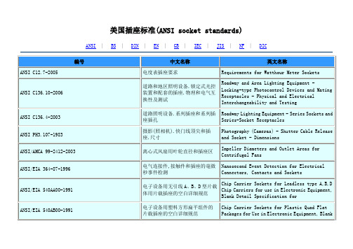
美国插标准
电连接器和插座的电容试验程序
Capacitance Test Procedure for Electrical Connectors and Sockets
ANSI/EIA-364-52A-2003
连接器/插座中使用的触点终端的软钎焊性的TP52试验程序
TP 52 Test Procedures for Solderability of Contact Terminations Use in Connectors/Sockets
ANSI/EIA-540A000-A-1990
ANSI/EIA 540AA00-1991
电子设备用无引线A、B、D型片载体用片载插座的空白详细规范
Chip Carrier Sockets for Leadless type A,B,D Chip Carriers for use in Electronic Equipment, Blank Detail Specification for
Combustion Characteristics Test Procedure for Electrical Connector Housing, Connector Assemblies and Sockets
ANSI/EIA-364-82A-2005
电连接器套、连接器组件和插座的塑料腐蚀性试验程序
Roadway and Area Lighting Equipment - Locking-type Photocontrol Devices and Mating Receptacles - Physical and Electrical Interchangeability and Testing
西门子低压电器快速选型手册

A- 不带欠压 N- 带欠压 220VAC/DC/ 无延时 P- 带欠压 380VAC/ 无延时 S- 带欠压 220VAC/DC 延时 T- 带欠压 380VAC/ 延时
辅助触点 4-4NO+4NC , 2-2NO+2NC 7-6NO+2NC , 8-5NO+3NC
3WL 型号标识
3WL1 2 20 4 CB 3 6 4 G A 4 -Z 附加选项
3WT 框架断路器快速选型表
9
3WT 榧架断路器,抽屉式,快速选型表
10
3VT 塑壳断路器快速选型表
11
第二部分 电动机控制产品
软起动器选型表
12
3RW34 熔断器选型表
14
3RW22 熔断器选型表
15
3RW22 选型指导
16
短路电流高达 50kA 非熔断器保护的电机馈电装置
18
非熔断器保护的电机馈电装置
1000 ~ 2500A
3200A
1280 ~ 3200A
附件说明: • 未加说明时: 1. 带电气合闸线圈: AC 220V/ DC 220V 2. 带储能电机: AC 220V/ DC 220V 3. 辅助触头: 2 常开 + 2 常闭 4. 无分励脱扣器,无欠压脱扣器
一舟技术指标

第一幸技术指标 (1)超五类非屏蔽系列 (1)超五类非屏蔽线缆D135-G (1)超五类非屏蔽配线架P197-24 (3)超五类非屏蔽模块M245 (4)超五类非屏蔽跳线 (5)超五类屏蔽系列 (7)超五类屏蔽线缆D145-G (7)超五类屏蔽品五架P198-24 (8)超五类屏蔽模块M247 (8)超五类屏蔽跳跳 (9)六类非屏蔽系列 (10)六六非屏蔽线缆D165-G (10)六六非屏蔽模块M255 (11)六类非屏蔽配线架P197-24A (12)六类屏蔽系列 (13)六类屏蔽线缆D185 (13)六类屏蔽犯线架P199-24 (14)六类屏蔽模块M257 (15)PB服务器机柜系列图片 (16)PB服务器机柜系列技术参数 (16)P2系列机柜图片 (18)P2系列机柜技术规格参数 (18)机柜配件图片 (20)地面信息、语音插座:S955A-1A (21)地面信息、语音插座:S955B-A (21)第一章技术指标超五类非屏蔽系列1.1.1 超五类非屏蔽线缆D135-G产品特点:超过Cat5E类标准单层铝箔结构,有效屏蔽外来电磁干扰高性能的高速电缆,支持带宽350MHz可以支持千兆以太网应用IS0/IEC11801, TIA/EIA 568B的超五类标准,满足EMC要求符合UL的CMR阻燃级别线规:24AWG,外径最大承受拉力:低烟无卤产品符合相关阻燃(IEC332/3)、低烟(IEC1034)、无卤(IEC754)标准提供20年质量保证主要物理参数:重量(普通):1000ft 0重量(低烟无卤):1000ft (12kg/)外皮厚度:()外径(普通):()外径(低烟无卤):()固定时弯曲半径:224mm;牵引时弯曲半径:248nlm拉伸强度:W93N;包装:纸箱,305米/箱最大拉力:25lbs ()工作温度(室内):-4° F到140。
F (-20℃到60℃)&工作温度(室外):-40° F到140° F (-40 C到60℃)烟密度:符合GB/T17651-1998 (等效于IEC 61034)毒性:符合GB/T 176507998 等效于IEC 60754)燃烧性能:符合IEC 60332-1线规:24AWG主要电气参数:NVP (室内):70% NVP (室外):62%最大直流电阻:100m*最大直流电阻不平衡:3%互电容@1 KHz: 100m绝缘电压:1250V/60Hz, 1Min环路电阻(20℃时):<1760/km特性阻抗:100±15Q容抗:54nF/100m满足标准:ANSl/TIA/EIA Cat5eI SO/1 EC 11801: 2002 (Edition 2) Class DCENELECEN50173: 2002 (Edition 2) Cat5eIEC754part2, IEC1034part1, IEC332part1, NES7131.1.2超五类非屏蔽配线架P197-24产品特点:满足超五类标准防潮、抗冲击设计,机械物理性高信息模块、配线架互换通用结构化设计,标准19英寸结构,安装方便标注T568A/B标识,易于端接符合TIA/EIA568B 和IS0/IEC11801 标准非屏蔽配线架后面另配有电缆导线架,方便固定线缆,防止线缆端接不良前端配有标签,方便端口标识采用全程屏蔽,提供最佳的EMC性能及传输性能产品提供20年质保主要物理参数:高度:()宽度:19in ()深度:(12cm)防火等级:UL-rated 94V-0工作温度:14° F 到140° F (70°C到60℃)存储温度:-40° F 到158° F (-40℃到70℃)湿度:95% (non-condensing)插拔次数:2750次主要电气参数:]最小绝缘阻抗:500Megaohms额定电流:(20℃)最小直流稳定电压:1000VAC RMS (60Hz接点到接点)1500VAC RMS (60Hz 表面传导)TIA/EIA 标准:5e1.1.3超五类非屏蔽模块M245X=0-9表示模块的颜色,如下定义:0 一乳白;1 一纯白;2 —蓝色;3一红色; 4一黑色;5 —绿色;6—橙色:7 —黄色:8 一紫色;9一灰色产品说明:采用专利的1101 DC设计。
(完整word)IEC60335

国际标准 IEC60335-1第四版2001-05家用和类似用途电器的安全第一部分:通用要求Safety of household and similar electrical appliancesParts 1:General requirements前言1)IEC(国际电工委员会)是由所有的国家电工委员会(IEC国家委员会)组成的国际标准化组织,其宗旨是促进在电气和电子领域有关标准化问题上的国际间合作。
为此,IEC开展国际标准化活动,并出版国际标准。
这些标准的制定委托各技术委员会完成.任何对该技术问题感兴趣的IEC国家委员会均可参加制定工作.与IEC有联系的国际、政府及非政府组织也可以参加这项工作。
IEC与国际标准化组织(ISO)在两个组织协议的基础上密切合作。
2)由所有对该问题特别感兴趣的国家委员会都参加的技术委员会所制定的IEC有关技术问题正式决议或协议,尽可能代表了对所涉及的问题在国际上的一致意见。
3)这些正式决议或协议,以标准、技术报告或导则等形式出版,并在此意义上被各国家委员会接受。
4)为了在国际上取得一致,IEC国家委员会同意在其国家及地区标准中尽可能最大范围地使用IEC国家标准。
IEC标准与相应的国家地区标准之间的差异应在后者中清楚地标出。
5)IEC并未制定认可标志的程序。
对有某设备宣称其符合IEC的某一项标准时,IEC对此不负任何责任。
6)本国际标准中的某些内容有可能涉及一些专利权问题,对此应引起注意。
IEC组织不负责识别任何这样的专利权问题。
本标准由IEC第61技术委员会(家用和类似用途电器的安全)制定。
本标准的第四版取代1991年的第三版及其修正件1(1994)和修正件2(1999)。
它构成了一个技术上的修订本。
有关本标准被通过时表决的全部材料可在上面所示的表决报告中找到.该通用要求(Part 1)要与适合的特殊要求(Part 2)结合使用,在特殊要求中包括了对通用要求中对应条款的补充和修正以给出对每种产品的有关要求。
IEC TRF 报告模板清单列表2016
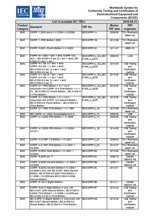
2016-04-15Product Category Standard TRF No.MasterTRF dateTRForiginatorEMC CISPR 11:2003 (ed.4) + A1:2004 + A2:2006IECCISPR11A2008-06TÜV RheinlandJapan Ltd. EMC CISPR 11 (Fifth Edition): 2009IECCISPR11B2012-08TÜV RheinlandJapan Ltd. EMC CISPR 13:2001 (Fourth Edition) + A1:2003IECCISPR13A2011-01MEEI Kft.EMC CISPR 14-1 (ed4) + am1 + am2; CISPR 14-2 (ed1) ; IEC 61000-3-2 (ed (2) + am 1 +am2; IEC61000-3-3 (ed1) + am1IECCISPR14_1&2_IEC61000_3_2&3A2008-03LCIEEMC CISPR 14-1 (ed. 5) + am1 + am2CISPR 14-2 (ed. 1) + am1 + am2IEC 61000-3-2 (ed. 3) + am1 + am2IEC 61000-3-3 (ed. 2)IECCISPR14_1&2_IEC61000_3_2&3C2014-04VDE TestingandCertificationInstituteEMC CISPR 14-1 (ed. 5) + am1 + am2CISPR 14-2 (ed. 1) + am1 + am2IEC 61000-3-2 (ed. 3) + am1 + am2IEC 61000-3-3 (ed. 3)IECCISPR14_1&2_IEC61000_3_2&3D2014-06VDE TestingandCertificationInstituteEMC CISPR 14-1 (Fifth Edition) + A1 + A2 inconjunction with CISPR 14-2 (First Edition) + A1 +A2 , IEC 61000-3-2 (Fourth Edition) , IEC 61000-3-3 (Third Edition)IECCISPR14_1&2_IEC61000_3_2&3E2015-05VDE TestingandCertificationInstituteEMC CISPR 14-1 (Fifth Edition) + A1 + A2 inconjunction with CISPR 14-2 (Second Edition),IEC 61000-3-2 (Fourth Edition) , IEC 61000-3-3(Third Edition)IECCISPR14_1&2_IEC61000_3_2&3F2015-05VDE TestingandCertificationInstituteEMC CISPR 14-1:1993 (Third Edition) + A1:1996IECCISPR14_1D2013-09TÜV RheinlandJapan Ltd. EMC IEC CISPR 14-1:2002 (Consolidated ed.4.2)IECCISPR14_1A2006-05VDE EMC CISPR 14-1:2005 (Fifth Edition) + A1:2008IECCISPR14_1C2009-08VDE TestingandCertificationInstituteEMC CISPR 14-1:2005 (Fifth Edition) + A1:2008 + A2:2011IECCISPR14_1E2014-05VDE TestingandCertificationInstituteEMC CISPR 14-2:1997 (1st Edition) + A1:2001IECCISPR14_2A2008-02TÜV RheinlandJapan Ltd.EMC CISPR 14-2:1997 (First Edition) + A1:2001 + A2:2008IECCISPR14_2C2014-07TÜV RheinlandJapan Ltd.EMC CISPR 15:2000 (Sixth Edition) + A1:2001 + A2:2002IECCISPR15D2013-06TÜV RheinlandJapan Ltd.EMC CISPR 15:2005 (ed. 7)IECCISPR15A2008-10IntertekSEMKO ABEMC CISPR 15:2005 (Seventh Edition) + A1:2006 + A2:2008IECCISPR15B2009-11IntertekSEMKO ABEMC CISPR 15:2005 (Seventh Edition)+ A1:2006 +A2:2008 in conj. with IEC 61547: 2009 (SecondEdition), IEC 61000-3-2:2005 (Third Edition) +A1:2008 + A2:2009 and IEC 61000-3-3:2008(Second Edition)IECCISPR15C2012-01VDEEMC CISPR 15: 2013 (Eighth Edition)IECCISPR15E2013-11IntertekSEMKO ABEMC CISPR 15:2013 (Eight Edition) in conj. withIEC 61547: 2009 (Second Edition), IEC 61000-3-2:2005 (Third Edition) + A1:2008 + A2:2009 andIEC 61000-3-3:2013 (Third Edition)IECCISPR15F2014-03VDE TestingandCertificationInstituteEMC IEC CISPR 15 (Eighth Edition) in conjunction with IECCISPR15G2015-05VDE TestingList of available IEC TRFs2016-04-15Product Category Standard TRF No.MasterTRF dateTRForiginator List of available IEC TRFsEMC IEC CISPR 15 (Eighth Edition) + A1:2015 inconjunction with IEC 61547 (Second Edition), IEC61000-3-2 (Fourth Edition), IEC 61000-3-3 (ThirdEdition)IECCISPR15H2015-05VDE TestingandCertificationInstituteEMC CISPR 15:2013 (Eighth Edition) + A1:2015IECCISPR15I2015-10IntertekSEMKO AB EMC CISPR 20:2006 (Sixth Edition)IECCISPR20A2011-01MEEI Kft. EMC IEC/CISPR22: 2005 Fifth Ed. with Am.1: 2005 andAm. 2; 2006IECCISPR22A2007-04UL Inc. EMC IEC CISPR22: 2008 Sixth Edition IECCISPR22B2010-06UL Inc. EMC IEC/CISPR 24:1997 (First Ed.) with Am. 1: 2001and Am. 2: 2002IECCISPR_24A2006-09UL Inc. EMC IEC CISPR 24:2010 (Second Edition) IECCISPR24B2011-08UnderwritersLaboratoriesInc. EMC IEC CISPR32: 2015 (Second Edition)IECCISPR32A2015-06IMQ S.p.A.SAFE IEC 60044-1:1996 (First Edition) + A1:2000 + A2:2002IEC60044_1A2010-04KEMA QualityB.V.MEAS IEC 60044-7:1999 (First Edition) IEC60044_7A2014-08TÜV RheinlandInterCert Kft.,MEEI Division MEAS IEC 60044-8:2002 (First Edition) IEC60044_8A2014-08TÜV RheinlandInterCert Kft.,MEEI Division TRON IEC 60065:98I0065__C1998-12BEAB TRON IEC 60065:2001IEC60065E2004-08ASATABEAB TRON IEC 60065:2001 (Seventh Edition) + A1:2005 IEC60065J2010-03IntertekSEMKO ABTRON IEC 60065:2001 (Seventh Edition) + A1:2005 + A2:2010IEC60065K2010-10IntertekSEMKO ABTRON IEC 60065:2014 (Eight Edition)IEC60065L2014-08IntertekSEMKO AB SAFE IEC 60076-2: 2011 (Third Edition)IEC60076_2A2014-07TÜV RheinlandInterCert Kft.,MEEI Division SAFE IEC 60076-3: 2000 (Second Edition)IEC60076_3A2014-07TÜV RheinlandInterCert Kft.,MEEI Division SAFE IEC 60076-5: 2006 (Third Edition)IEC60076_5A2014-07TÜV RheinlandInterCert Kft.,MEEI Division SAFE IEC 60076-10: 2001 (First Edition)IEC60076_10A2014-07TÜV RheinlandInterCert Kft.,MEEI Division SAFE IEC 60076-11: 2004 (First Edition)IEC60076_11A2014-07TÜV RheinlandInterCert Kft.,MEEI Division BATT IEC 60086-1:2015 (Twelfth Edition)IEC60086_1A2016-01DEKRACertificationB.V. BATT IEC 60086-2:2015 (Thirteenth Edition)IEC60086_2A2016-01DEKRACertificationB.V. BATT IEC 60086-3:2011 (Third Edition)IEC60086_3A2016-01DEKRACertificationB.V. BATT IEC 60086-4 (Third Edition): 2007IEC60086_4A2012-09IntertekSEMKO AB BATT IEC 60086-4:2014 (Fourth Edition)IEC60086_4B2015-02IntertekSEMKO AB2016-04-15Product Category Standard TRF No.MasterTRF dateTRForiginator List of available IEC TRFsPROT IEC 60127-1:2006 withIEC 60127-2:2003 + A1:2003 IEC60127_2A_I2008-05VDE TestingandCertificationInstitutePROT IEC 60127-1:2006 with IEC 60127-2:2003 + A1:2003 + A2:2010Cartridge fuse-links IEC60127_2B_I2011-07VDE TestingandCertificationInstitutePROT IEC 60127-2:2003 + A1:2003 + A2:2010 with IEC 60127-1:2006 + A1:2011Cartridge fuse-links IEC60127_2C_I2013-02VDE TestingandCertificationInstitutePROT IEC 60127-2:2014 withIEC 60127-1:2006 + A1:2011 + A2:2015Cartridge fuse-links IEC60127_2D_I2015-11VDE TestingandCertificationInstitutePROT IEC 60127-1:2006 withIEC 60127-2:2003 + A1:2004Cartridge fuse-links, homogenous series,minimum rating IEC60127_2A_II2008-05VDE TestingandCertificationInstitutePROT IEC 60127-1:2006 with IEC 60127-2:2003 + A1:2003 + A2:2010Cartridge fuse-links, homogenous series,minimum rating IEC60127_2B_II2011-07VDE TestingandCertificationInstitutePROT IEC 60127-2:2003 + A1:2003 + A2:2010 with IEC 60127-1:2006 + A1:2011Cartridge fuse-links, homogenous series,minimum rating IEC60127_2C_II2013-02VDE TestingandCertificationInstitutePROT IEC 60127-2:2014 withIEC 60127-1:2006 + A1:2011 + A2:2015Cartridge fuse-links, homogenous series,minimum rating IEC60127_2D_II2015-11VDE TestingandCertificationInstitutePROT IEC 60127-1:2006 withIEC 60127-2:2003 + A1:2003Cartridge fuse-links, homogenous series,maximum rating IEC60127_2A_III2008-05VDE TestingandCertificationInstitutePROT IEC 60127-1:2006 with IEC 60127-2:2003 + A1:2003 + A2:2010Cartridge fuse-links, homogenous series,maximum rating IEC60127_2B_III2011-07VDE TestingandCertificationInstitutePROT IEC 60127-2:2003 + A1:2003 + A2:2010 with IEC 60127-1:2006 + A1:2011Cartridge fuse-links, homogenous series,maximum rating IEC60127_2C_III2013-02VDE TestingandCertificationInstitutePROT IEC 60127-2:2014 withIEC 60127-1:2006 + A1:2011 + A2:2015Cartridge fuse-links, homogenous series,maximum rating IEC60127_2D_III2015-11VDE TestingandCertificationInstitutePROT IEC 60127-1:2006 withIEC 60127-2:2003 + A1:2003Cartridge fuse-links with pigtails IEC60127_2A_IV2008-05VDE TestingandCertificationInstitutePROT IEC 60127-1:2006 with IEC 60127-2:2003 + A1:2003 + A2:2010Cartridge fuse-links with pigtails IEC60127_2B_IV2011-07VDE TestingandCertificationInstitutePROT IEC 60127-2:2003 + A1:2003 + A2:2010 with IEC 60127-1:2006 + A1:2011Cartridge fuse-links with pigtails IEC60127_2C_IV2013-02VDE TestingandCertificationInstitute2016-04-15Product Category Standard TRF No.MasterTRF dateTRForiginator List of available IEC TRFsPROT IEC 60127-3:1988 + A1:1991 + Cor.1:1994 + Cor.2:1996 + A2:2002 with IEC 60127-1:2006 IEC60127_3A_I2009-04VDE TestingandCertificationInstitutePROT IEC 60127-3:1988 + A1:1991 + Cor.1:1994 + Cor.2:1996 + A2:2002 with IEC 60127-1:2006 +A1:2011Sub-miniature fuse-links IEC60127_3B_I2013-03VDE TestingandCertificationInstitutePROT IEC 60127-3:2015 with IEC 60127-1:2006 + A1:2011Sub-miniature fuse-links IEC60127_3C_I2015-11VDE TestingandCertificationInstitutePROT IEC 60127-3:1988 + A1:1991 + Cor.1:1994 + Cor.2:1996 + A2:2002 in conjunction with IEC60127-1:2006Sub-miniature fuse-links, homogenous series,minimum rating IEC60127_3A_II2009-04VDE TestingandCertificationInstitutePROT IEC 60127-3:1988 + A1:1991 + Cor.1:1994 + Cor.2:1996 + A2:2002 with IEC 60127-1:2006 +A1:2011Sub-miniature fuse-links, homogenous series,minimum rating IEC60127_3B_II2013-03VDE TestingandCertificationInstitutePROT IEC 60127-3:2015 with IEC 60127-1:2006 +A1:2011Sub-miniature fuse-links, homogenous series,minimum rating IEC60127_3C_II2015-11VDE TestingandCertificationInstitutePROT IEC 60127-3:1988 + A1:1991 + Cor.1:1994 + Cor.2:1996 + A2:2002 in conjunction with IEC60127-1:2006Sub-miniature fuse-links, homogenous series,maximum rating sheet 1 and 2IEC60127_3A_III2009-04VDE TestingandCertificationInstitutePROT IEC 60127-3:1988 + A1:1991 + Cor.1:1994 + Cor.2:1996 + A2:2002 with IEC 60127-1:2006 +A1:2011Sub-miniature fuse-links, homogenous series,maximum rating sheet 1 and 2IEC60127_3B_III2013-03VDE TestingandCertificationInstitutePROT IEC 60127-3:2015 with IEC 60127-1:2006 +A1:2011Sub-miniature fuse-links, homogenous series,maximum rating sheet 1 and 2IEC60127_3C_III2015-11VDE TestingandCertificationInstitutePROT IEC 60127-3:1988 + A1:1991 + Cor.1:1994 + Cor.2:1996 + A2:2002 in conjunction with IEC60127-1:2006Sub-miniature fuse-links, homogenous series,maximum rating sheet 3 and 4IEC60127_3A_IV2009-04VDE TestingandCertificationInstitutePROT IEC 60127-3:1988 + A1:1991 + Cor.1:1994 + Cor.2:1996 + A2:2002 with IEC 60127-1:2006 +A1:2011Sub-miniature fuse-links, homogenous series,maximum rating sheet 3 and 4IEC60127_3B_IV2013-04VDE TestingandCertificationInstitutePROT IEC 60127-3:2015 with IEC 60127-1:2006 +A1:2011Sub-miniature fuse-links, homogenous series,maximum rating sheet 3 and 4IEC60127_3C_IV2015-11VDE TestingandCertificationInstitutePROT IEC 60127-4:2005 + Amendment 1 :2008 in conjunction with IEC 60127-1:2006 IEC60127_4A_I2009-04VDE TestingandCertificationInstitutePROT IEC 60127-4:2005 + Amendment 1 :2008 with IEC 60127-1:2006 + A1:2011IEC60127_4B_I2013-04VDE Testingand2016-04-15Product Category Standard TRF No.MasterTRF dateTRForiginator List of available IEC TRFsPROT IEC 60127-4:2005 (Third Edition) + A1 :2008 + A2:2012 with IEC 60127-1:2006 (Second Edition)+ A1:2011IEC60127_4C_I2015-11VDE TestingandCertificationInstitutePROT IEC 60127-4:2005 + Amendment 1 :2008 inconjunction with IEC 60127-1:2006Miniature fuses – Universal Modular Fuse-linkshomogenous series, minimum rating IEC60127_4A_II2009-04VDE TestingandCertificationInstitutePROT IEC 60127-4:2005 + Amendment 1 :2008with IEC 60127-1:2006 + A1:2011Miniature fuses – Universal Modular Fuse-linkshomogenous series, minimum rating IEC60127_4B_II2013-04VDE TestingandCertificationInstitutePROT IEC 60127-4:2005 (Third Edition) + A1 :2008 + A2:2012 with IEC 60127-1:2006 (Second Edition)+ A1:2011Miniature fuses – Universal Modular Fuse-links, homogenous series, minimum rating IEC60127_4C_II2015-11VDE TestingandCertificationInstitutePROT IEC 60127-4:2005 + Amendment 1 :2008 inconjunction with IEC 60127-1:2006Miniature fuses – Universal Modular Fuse-linkshomogenous series, maximum rating IEC60127_4A_III2009-04VDE TestingandCertificationInstitutePROT IEC 60127-4:2005 + Amendment 1 :2008with IEC 60127-1:2006 + A1:2011Miniature fuses – Universal Modular Fuse-linkshomogenous series, maximum rating IEC60127_4B_III2013-04VDE TestingandCertificationInstitutePROT IEC 60127-4:2005 (Third Edition) + A1 :2008 + A2:2012 with IEC 60127-1:2006 (Second Edition)+ A1:2011Miniature fuses – Universal Modular Fuse-links, homogenous series, maximum rating IEC60127_4C_III2015-11VDE TestingandCertificationInstitutePROT IEC 60127-7:2013 (First edition) in conjunction with IEC 60127-1:2006 + A1:2011IEC60127_7A2015-11VDE TestingandCertificationInstituteLITE IEC 60155:93 + A1:95I155___A1997-11IMQ LITE IEC 60155:1993 + A1:1995 + A2:2006IEC60155A2009-04IMQ S.p.A. HOUS IEC 60204-1 (Fifth Edition) + A1:2008IEC60204_1A2009-11Electrosuisse CABL IEC 60227-3:93 + A1:97I227_3_A1999-11KEMA CABL IEC 60227-4:92 + A1:97I227_4_A1999-11KEMA CABL IEC 60227-5:97 + A1:97I227_5_B1999-11KEMA CABL IEC 60227-5:1997 + A1:1997 + A2:2003 for usewith IEC 60227-1 and IEC 60227-2IEC60227_5C2005-06KEMACABL IEC 60227-5 (Third Edition): 2011 in conjunctionwith IEC 60227-1 (Third Edition): 2007 andIEC 60227-2 (Second Edition):1997 and A1: 2003IEC60227_5F2013-01CQCCABL IEC 60227-6:85 + A1:97I227_6_A1999-11KEMA CABL IEC 60227-6:2001(Third Edition) in conjunctionwith IEC 60227-1:2007 (Third Edition) and/orIEC 60227-2:1997 (Second Edition); A1:2003IEC60227_6A2009-01KEMA CABL IEC 60227-7:95I227_7_A1999-12KEMACABL IEC 60227-7:1995 (First Edition) +A1:2003 + A2:2011IEC60227_7B2014-10TÜV RheinlandInterCert Kft.,MEEI DivisionLITE IEC 60238:1996(ed.6) + A1:1997 + A2:1997IEC60238C2005-02CQC LITE IEC 60 238:2004(8 Edition) IEC60238D2006-05CQC LITE IEC 60238:2004(Eighth Edition) + A1:2008IEC60238E2009-04CQC LITE IEC 60238 (Eighth Edition): 2004 + A1: 2008 +A2:2011IEC60238F2011-12CQC2016-04-15Product Category Standard TRF No.MasterTRF dateTRForiginator List of available IEC TRFsCABL IEC 60245-4 (Third Edition) :2011 in conjunctionwith IEC 60245-1 (Fourth Edition) :2003 andA1:2007 and IEC 60245-2 (Second Edition) :1994and A1:1997, A2:1997IEC60245_4E2013-01CQCCABL IEC 60245-5:94I245_5_A1999-11KEMA CABL IEC 60245-6:94 + A1:97I245_6_A1999-11KEMA CABL IEC 60245-6:1994 (Second Edition) + A1:1997 +A2:2003 for use in conjunction with IEC 60245-1and IEC 60245 -2IEC60245_6C2012-11CQCCABL IEC 60245-7:94 + A1:97I245_7_A1999-11KEMA CABL IEC 60245-8:98I245_8_A1999-12KEMA CABL IEC 60245-8:1998 + A1:2003 for use with IEC60245-1 and IEC 60245-2IEC60245_8B2005-01KEMA CAP IEC 60252-1: 2001(First Edition)IEC60252_1A2005-11CQCCAP IEC 60252-1:2010 (Second Edition)IEC60252_1B2012-02CQCCAP IEC 60252-1:2010 (Second Edition) + A1:2013 IEC60252_1C2014-04CQCCAP IEC 60252-2:2003 (First Edition)IEC60252_2A2009-05CQCCAP IEC 60252-2:2010 (Second Edition)IEC60252_2B2011-11CQCCAP IEC 60252-2:2010 (Second Edition) + A1:2013 IEC60252_2C2014-04CQC CONT IEC 60255-1: 2009 (First Edition)IEC60255_1A2014-04TÜV RheinlandInterCert Ltd.(MEEI Division)CONT IEC 60255-27:2013 (Second Edition)IEC60255_27A2014-09IMQ S.p.A. PROT IEC 60269-1:86I2691__A1991-10EZU PROT IEC 60269-1:2006 (Fourth edition)IEC60269_1A2009-04EZU PROT IEC 60269-1:2006 (Fourth edition) + A1:2009IEC60269_1B2010-08EZU PROT IEC 60269-2:86I2692__A1991-10EZU PROT IEC 60269-2 : 2006 (third edition) (see also IEC60269-1:1998)IEC60269_2A2007-12EZUPROT IEC 60269-2 (Fourth edition): 2010see also IEC 60269 – 1:2006 (fourth edition)+A1:2009IEC60269_2B2011-04EZUPROT IEC 60269-2: 2013 (Fifth Edition) to be used inconjunction with IEC 60269-1:2006 (FourthEdition) + A1:2009IEC60269_2C2014-06EZUPROT IEC 60269-2-1:87I269201A1991-10EZU PROT IEC 60269-2-1: 2004 (see also IEC 60269-1:1998)IEC60269_2_1B2005-06LCIE PROT IEC 60269-3:87I2693__A1991-10EZU PROT IEC 60269-3 : 2006 (third edition) (see also IEC60269 – 1:1998)IEC60269_3A2008-02EZUPROT IEC 60269-3:2006 (Third edition) (see also IEC60269–1:2006)IEC60269_3B2009-04EZU PROT IEC 60269-3-1:94I269301A1995-11EZU PROT IEC 60269-4:86I2694__A1991-10EZU PROT IEC 60269-4:2006 (Fourth Edition) (see also IEC60269-1:2006)IEC60269_4A2008-10CQCPROT IEC 60269-4 (Fifth Edition) + A1:2012see also IEC 60269–1:2006 (Fourth edition) +A1:2009IEC60269_4B2012-12CQCPROT IEC 60269-6: 2010 (First Edition) for use inconjunction with IEC 60269 1:2006 (Fourth edition)+A1:2009IEC60269_6A2012-01VDEINST IEC 60309-1/2:97I3091-2A1998-07IMQ INST IEC 60309-1, 4th Edition (1999) & IEC 60309-2,4th Edition (1999)IEC60309_1-2B2000-11IMQINST IEC 60309-1, 4th Edition 1999 + A1:2005 and IEC60309-2, 4th Edition 1999 + A1:2005IEC60309_1-2D2009-05IMQ INST IEC 60309-1:1999 (Fourth Edition) + A1:2005 + IEC60309_1-2E2013-05IMQ S.p.A.2016-04-15Product Category Standard TRF No.MasterTRF dateTRForiginator List of available IEC TRFsINST IEC 60309-4:2006 (First Edition) in conjunctionwith IEC 60309-1: 1999 (Fourth Edition) + A1:2005and IEC 60309-2: 1999 (Fourth Edition) + A1:2005IEC60309_4B2009-05IMQ S.p.A.INST IEC 60309-4:2006 + A1: 2012 (First Edition) inconjunction with IEC 60309-1: 1999 (FourthEdition) + A1:2005 + A2:2012 and IEC 60309-2:1999 (Fourth Edition) + A1:2005 + A2:2012IEC60309_4C2013-05IMQ S.p.A.INST IEC 60320-1:94 + A1:95 + A2:96I320-1_B1998-07IMQ INST IEC 60320-1:2001 (2nd Edition) + A1:2007IEC60320_1A2008-10IMQ INST IEC 60320-1:2015 (Third Edition) IEC60320_1B2015-11IMQ S.p.A. INST IEC 60320-2-1:84I320201A1989-05IMQ INST IEC 60320-2-2:90I320202A1992-06IMQ INST IEC 60320-2-2:98I320202B1999-12IMQ INST IEC 60320-2-4:2005 (First Edition)+A1:2009 (seealso IEC 60320 1:2001 (Second Edition) +A1:2007)IEC60320_2_4B2014-06CQCHOUS IEC 60335-1:91 + A1:94I3351_E1996-01NEMKO HOUS IEC 60335-1:91 + A1:94 + A2:99I3351__F2000-03NEMKO HOUS IEC 60335-1:2001IEC60335_G2002-04NEMKO HOUS IEC 60335-1:2001 (incl. Corrigendum 1:2002) +A1:2004IEC60335_H2004-09NEMKO HOUS IEC 60335-1:2001 (4. Edition) (incl. Corrigendum1:2002) + A1:2004IEC60335_1J2006-05NEMKOHOUS IEC 60335-1:2001 (Fourth Edition) incl.Corrigendum 1:2002 + A1: 2004 + A2:2006 incl.Corrigendum 1:2006IEC60335_1S2012-03Nemko ASHOUS IEC 60335-1:2010 (Fifth Edition)IEC60335_1T2013-02Nemko AS HOUS IEC 60335-1:2010 (Fifth Edition) incl. Corr. 1:2010and Corr. 2:2011 + A1:2013IEC60335_1W2015-08Nemko ASHOUS IEC 60335-2-2:93I335202B/ 96-061996-03CEBEC HOUS IEC 60335 2 2:2002 (Fifth edition) + A1:2004 +A2:2006IEC60335_2_2A2007-11Electrosuisse HOUS IEC 60335-2-2: 2002 (5th Edition) + A1:2004 +A2:2006 in conjunction with IEC 60335-1:2001(4th Edition) (incl. Corrigendum 1:2002) + A1:2004+ A2:2006 (incl. Corrigendum 1:2006)IEC60335_2_2B2009-12LCIEHOUS IEC 60335-2-2: 2002 (6th Edition) 2009 inconjunction with IEC 60335-1:2001 (4th Edition)(incl. Corrigendum 1:2002) + A1:2004 + A2:2006(incl. Corrigendum 1:2006)IEC60335_2_2C2010-09LCIEHOUS IEC 60335-2-2: 2009 (Sixth Edition) in conjunctionwith IEC 60335-1:2010 (Fifth Edition) (incl.Corrigendum 1:2010)IEC60335_2_2E2013-03LCIEHOUS IEC 60335-2-2: 2009 (Sixth Edition) + A1 : 2012 inconjunction with IEC 60335-1:2010 (Fifth Edition)(incl. Corrigendum 1:2010)IEC60335_2_2F2013-04LCIEHOUS IEC 60335-2-2:2009 (Sixth Edition) + A1:2012 inconjunction with IEC 60335-1:2010 (Fifth Edition)(incl. Corrigendum 1:2010) and Corr. 2:2011 +A1:2013IEC60335_2_2H2016-03LCIEHOUS IEC 60335-2-2:2009 (Sixth Edition) + A1:2012 andIEC 60335-2-3:2012 (Sixth edition) + A1:2015 andIEC 60335-2-54:2008 (Fourth Edition) + A1:2015for use in conjunction withIEC 60335-1:2010 (Fifth Edition) + A1:2013IEC60335_2_2&3&54A2016-02IMQ S.p.A.HOUS IEC 60335-2-2:2009 (Sixth Ed.) & IEC 60335-2-10:2002 (Fifth Ed.) + A1:2008 in conjunction withIEC 60335-1:2001 (Fourth Ed.) (incl. Cor. 1:2002)+ A1:2004 + A2:2006 (incl. Cor. 1:2006)IEC60335_2_2&10A2013-01UL(US)2016-04-15Product Category Standard TRF No.MasterTRF dateTRForiginator List of available IEC TRFsHOUS IEC 60335-2-2:2009 (Sixth Edition) + A1:2012 &IEC 60335-2-10:2002 (Fifth Edition) + A1:2008 inconjunction with IEC 60335-1:2010 (Fifth Edition)(incl. Corrigendum 1:2010 and Corrigendum2:2011) + A1:2013IEC60335_2_2&10C2015-10UL(US)HOUS IEC 60335-2-2:2009 (6th Edition) & IEC 60335-2-54:2008 (4th Edition) for use in conjunction withIEC 60335-1:2001 (4th Edition) incl. Corrigendum1:2002 + A1:2004 + A2:2006 incl. Corrigendum1:2006 and IEC 62233:2005 (1st Edition)IEC60335_2_2&54A2010-04IMQ S.p.A.HOUS IEC 60335-2-2: 2009 (Sixth Edition) + A1:2012 ;IEC 60335-2-54:2008 (Fourth Edition) inconjunction with IEC 60335-1:2010 (Fifth Edition)(incl. Corrigendum 1:2010)IEC60335_2_2&54B2013-11IMQ S.p.A.HOUS IEC 60335-2-2: 2009 (Sixth Edition) + A1:2012 ;IEC 60335-2-54:2008 (Fourth Edition) inconjunction with IEC 60335-1:2010 (Fifth Edition)(incl. Corrigendum 1:2010) + A1:2013IEC60335_2_2&54C2015-06IMQ S.p.A.HOUS IEC 60335-2-2:2009 (Sixth Edition) + A1:2012 andIEC 60335-2-54:2008 (Fourth Edition) + A1:2015for use in conjunction with IEC 60335-1:2010 (FifthEdition) + A1:2013IEC60335_2_2&54D2015-12IMQ S.p.A.HOUS IEC 60335-1:2001 (4th Edition) (incl. Corrigendum1:2002) + A1:2004 + A2:2006 (incl. Corrigendum1:2006), IEC 60335-2-2: 2002 (5th Edition) +A1:2004 + A2:2006, IEC 60335-2-69:2002 (3thEdition) + A1:2004IEC60335_2_2&69A2008-02CQCHOUS IEC 60335-1:2010 (Fifth Edition)IEC 60335-2-2: 2009 (Sixth Edition)IEC 60335-2-69:2002 (Third Edition) +A1:2004+A2:2007IEC60335_2_2&69B2012-08TUV RheinlandLGA ProductsHOUS IEC 60335-2-2:2009 (Sixth Edition) + A1 : 2012 IEC 60335-2-69:2012 (Fourth Edition)IEC 60335-1:2010 (Fifth Edition) (incl.Corrigendum 1:2010)IEC60335_2_2&69C2014-10TUV RheinlandLGA ProductsHOUS IEC 60335-2-3:93I335203B1996-09NEMKO HOUS IEC 60335-2-3:93 + A1:99 + A2:99, IEC 60335-1:91 + A1:94 + A2:99IEC60335_2_3C2002-02NEMKO HOUS IEC 60335-2-3:2012 (Sixth edition) in conjunctionwith IEC 60335-1:2010 (Fifth Edition)IEC60335_2_3F2012-10KTLHOUS IEC 60335-2-3:2002 (5th Edition) +A1:2004 inconjunction with IEC 60335-1:2001 (4th Edition)(incl. Corr.1:2002) +A1:2004 +A2:2006 (incl.Corr.1:2006)IEC60335_2_3G2012-11KTLHOUS IEC 60335-2-3:2002 (Fifth Edition) + A1:2004+A2:2008 in conjunction with IEC 60335-1: 2001(Fourth Edition) (incl. Corr.1:2002)+A1:2004+A2:2006 (incl. Corr.1:2006)IEC60335_2_3H2012-11KTLHOUS IEC 60335-2-3:2002 (Fifth Edition) + A1:2004+A2:2008 in conjunction with IEC 60335-1:2010(Fifth Edition)IEC60335_2_3I2012-12KTLHOUS IEC 60335-2-3:2012 (Sixth edition) in conj. WithIEC 60335-1:2010 (Fifth Edition) incl. Corr. 1:2010and Corr. 2:2011 + A1:2013IEC60335_2_3J2014-10KTLHOUS IEC 60335-2-3:2012 (Sixth Edition) + A1:2015 inconjunction with IEC 60335-1 2010 (Fifth Edition)incl. Corr. 1:2010 and Corr. 2:2011 + A1:2013IEC60335_2_3K2015-12KTL2016-04-15Product Category Standard TRF No.MasterTRF dateTRForiginator List of available IEC TRFsHOUS IEC 60335-2-3:2002 (Fifth Edition) + A1:2004 +A2:2008 and IEC 60335-2-54:2008 (FourthEdition) for use in conjunction withIEC 60335-1:2010 (Fifth Edition) + A1:2013IEC60335_2_3&54B2015-06IMQ S.p.A.HOUS IEC 60335-2-3:2002 (Fifth Edition) + A1:2004+A2:2008 and IEC 60335 2 85:2002 (Secondedition) + A1:2008 in conjunction with IEC 60335-1:2010 (Fifth Edition)IEC60335_2_3&85A2014-01SGS CEBECHOUS IEC 60335-2-3:2002 (Fifth Edition) + A1:2004+A2:2008 and IEC 60335 2 85:2002 (Secondedition) + A1:2008 in conjunction with IEC 60335-1:2010 (Fifth Edition) + A1:2013IEC60335_2_3&85B2015-06SGS CEBECHOUS IEC 60335-2-4:93 I335204B1996-09LCIE HOUS IEC 60335-2-4:93 & IEC 60335-2-7:93I3352C1A1996-09LCIE HOUS IEC 60335-2-4:2002 (5th Ed.) and IEC 60335-2-7:2002 (6th Ed.) use in conjunction with IEC 60335-1:2001 (4th Ed.)IEC60335_2_4&7C2003-03VDEHOUS IEC 60335-2-4:2002 (5th Ed.) and IEC 60335-2-7:2002 (6th Ed.) use in conjunction with IEC 60335-1:2001 +A1:2004IEC60335_2_4&7D2006-06CQCHOUS IEC 60335-2-4:2008 (Fifth Edition) andIEC 60335-2-7:2008 (Sixth Edition) In conjunctionwith IEC 60335-1:2001 (Fourth Edition) + A1:2004+ A2:2006+ incl. Corrigenda: 2002 and :2005IEC60335_2_4&7F2012-08CQCHOUS IEC 60335-2-4:2008 (Sixth Edition)+A1:2012 andIEC 60335-2-7:2008 (Seventh Edition) +A1 :2011in conjunction with IEC 60335-1:2010 (FifthEdition) ) incl. Corrigendum 1:2010IEC60335_2_4&7G2014-06CQCHOUS IEC 60335-2-4:2008 (Sixth Edition) +A1:2012 andIEC 60335-2-7:2008 (Seventh Edition) + A1 :2011in conjunction with IEC 60335-1:2010 (FifthEdition) ) incl. Corrigendum 1:2010 and Corr.2:2011 + A1:2013IEC60335_2_4&7H2015-07CQCHOUS IEC 60335-2-4:2002 (5th Ed.) and IEC 60335-2-7:2002 (6th Ed.) and IEC 60335-2-11:2002 (6thEd.) + A1:2003 use in conjunction with IEC 60335-1:2001 (4th Ed.)IEC60335_2_4&7&11A2003-07VDEHOUS IEC 60335-2-4:2008 (Sixth edition) in conjunctionwith IEC 60335-1:2001 (Fourth edition) (incl.Corr.1:2002) + A1:2004 (incl. Corr.1:2005) +A2:2006 (incl. Corr.1:2006)IEC60335_2_4C2012-08EurofinsHOUS IEC 60335-2-4:2008 (Sixth Edition) used inconjunction with: IEC 60335-1:2010 (Fifth Edition)IEC60335_2_4D2013-10EurofinsHOUS IEC 60335-2-4:2008 (Sixth Edition) + A1:2012used in conjunction with: IEC 60335-1:2010 (FifthEdition)IEC60335_2_4E2013-10EurofinsHOUS IEC 60335-2-4:2008 (Sixth Edition) + A1:2012used in conjunction with: IEC 60335-1:2010 (FifthEdition) + A1:2013IEC60335_2_4F2015-06EurofinsHOUS IEC 60335-2-5:84 + A1:88 (see also IEC 60335-1:76 + A1:77 + A2:79 + A3:82 + A4:84 + A5:86 +A6:88)i335205a1991-02LCIEHOUS IEC 60335-2-5:92I335205B1998-02LCIE HOUS IEC 60335-2-5: 2002 (Fifth edition) + A1:2005 withIEC 60335 1: 2001 (Fourth ed.) (incl. Corr.1: 2002)+ A1:04 + A2:06 (incl. Corr. 1: 2006)IEC60335_2_5A2008-05LCIE2016-04-15Product Category Standard TRF No.MasterTRF dateTRForiginator List of available IEC TRFsHOUS IEC 60335-2-5:2002 (Fifth edition) + A1:2005+ A2:2008IEC 60335-1:2010 (Fifth Edition)IEC 62233:2005 (First Edition)IEC60335_2_5D2012-03VDE TestingandCertificationInstituteHOUS IEC 60335 2 5:2012 (Sixth Edition) in conjunction with IEC 60335-1:2010 (Fifth Edition) incl. Corr.1:2010 and Corr. 2:2011 + A1:2013IEC60335_2_5E2014-04VDE TestingandCertificationInstituteHOUS IEC 60335-2-6:86 + A1:88 + A2:90 (see also IEC60335-1:76 + A1:77 + A2:79 + A3:82 + A4:84 +A5:86 + A6:88)I335206A1992-02LCIEHOUS IEC 60335-2-6:97I335206B1999-12LCIE HOUS IEC 60335-2-6:97 (see also IEC 60335-1:1991 +A1:1994 + A2:1999)IEC60335_2_6C2002-08LCIEHOUS IEC 60335-2-6:2002 (for use with IEC 60335-1:2001)IEC60335_2_D2003-02LCIEHOUS IEC 60335-2-6:2002 with IEC 60335-1:2001(Fourth Edition) + Corrigendum 2002 + A1:2004IEC60335_2_6E2006-10LCIEHOUS IEC 60335-2-6 2002 (Fifth edition) + A1:2004 inconj. with IEC 60335 1:2001 (Fourth ed.) (incl.Corr.1:2002) + A1:04 + A2:06 (incl. Corr. 1:2006)IEC60335_2_6F2008-07LCIEHOUS IEC 60335-2-6 2002 (Fifth edition) + A1:2004 +A2:2008 in conjunction with IEC 60335 1:2001(Fourth ed.) (incl. Corr.1:2002) + A1:04 + A2:06(incl. Corr. 1:2006)IEC60335_2_6G2011-02LCIEHOUS IEC 60335-2-6 2002 (Fifth edition) + A1:2004 +A2:2008 in conjunction with IEC 60335-1:2010(Fifth edition)IEC60335_2_6N2016-03LCIEHOUS IEC 60335-2-6:2014 (Sixth edition) in conjunctionwith IEC 60335-1:2010 (Fifth Edition) incl. Corr.1:2010 and Corr. 2:2011 + A1:2013IEC60335_2_6O2016-03LCIEHOUS IEC 60335-2-6:2002 (Fifth edition) + A1:2005 andIEC 60335-2-13:2002 (Fifth edition) + A1:2004used in conjunction with IEC 60335-1:2001 (incl.Corrigendum 1:2002) + A1:2004IEC60335_2_6&13A2005-05IMQHOUS IEC 60335-2-6:2002 (5. edition) + A1:2004 +A2:2008IEC 60335-2-9:2002 (5. edition) + A1:2004 +A2:2006IEC 60335-2-25:2002 (5. edition) + A1:2005 +A2:2006IEC 60335-1:2001 (4. edition) (incl. Corr.1:2002) +A1:2004 (incl. Corr.1:2005) + A2:2006 (incl.Corr.1:2006) and/orIEC60335_2_6&9&25A2008-08VDEHOUS IEC 60335-2-6:2002 (5th edition) + A1:2004 +A2:2008, IEC 60335-2-25:2002 (5th edition) +A1:2005 + A2:2006, IEC 60335-1:2001 (4thedition) (incl. Corr.1:2002) + A1:2004 (incl.Corr.1:2005) + A2:2006 (incl. Corr.1:2006) and/orIEC 62233:2005 (1st edition)IEC60335_2_6&25A2009-12VDEHOUS IEC 60335-2-6:2002 (Fifth Edition) + A1:2004 + A2:2008, IEC 60335-2-25:2010 (Sixth Edition)in conjunction with IEC 60335-1:2010 (FifthEdition)IEC60335_2_6&25B2012-09VDE TestingandCertificationInstituteHOUS IEC 60335-2-6:2014 (Sixth Edition)IEC 60335-2-25:2010 (Sixth Edition) + A1:2014 inconjunction with IEC 60335-1:2010 (Fifth Edition)incl. Corr. 1:2010 and Corr. 2:2011 + A1:2013IEC60335_2_6&25C2015-09VDE TestingandCertificationInstitute。
3v化器材使用、检测标准
目录一、 BG2(3)-130/25道变压器 (1)二、 BG2-260/25轨道变压器 (8)三、 BGK-130/25电抗变压器 (14)四、 BG2(3)-L130/25轨道变压器 (18)五、 BG2(3)-L260/25轨道变压器 (25)六、 BGM-150/25型电码化轨道变压器 (33)七、 BGT调谐轨道变压器 (38)八、 QY-T抑制器 (42)九、抽头电阻 (46)十、HPT-ZD调相匹配盒 (48)十一、QT-25调相器 (53)十二、BE-F扼流变压器 (57)十三、售后服务及质量保证承诺 (63)一、BG2(3)-130/25轨道变压器1.产品用途及使用环境1.1用途:BG2(3)-130/25轨道变压器适用于3V化25Hz相敏轨道电路中作为送电端供电变压器。
根据轨道电路的类型和不同长度,供以不同的电压,使轨道继电器可靠工作。
1.2 型号:BG2-130/25采用CD型400Hz铁心;BG3-130/25采用CD型50Hz铁心。
1.3 使用环境变压器在下列环境条件下可以可靠地工作:a ) 周围空气温度;-40℃~ +70℃;b ) 周围空气相对湿度不大于90℅(25℃);c ) 大气压力不低于 70kPa(海拔高度不超过3000m);d ) 振动频率 10Hz~200Hz 、加速度幅值 20 m / s2;e ) 周围无引起爆炸危险的有害气体。
2.原理图图13.技术特性3.1.BG2-130/25 、BG3-130/25轨道变压器的电气特性如下表表 1 轨道变压器的电气特性3.2.轨道变压器空载时,一次侧空载电流符合表1的规定,二次侧各端子间的空载电压为额定值,符合表1的规定端电压允许误差不大于±5%。
3.3.轨道变压器满载时,二次侧各端子间的电压应不低于表1规定的额定值的90% 。
3.4.变压器四个绕组的Ⅰ1、Ⅰ2、Ⅱ1、Ⅲ1均为同名端,见图1所示。
3.5.在额定频率额定输入电压下,输出端接额定负载时变压器效率不小于85% 。
施耐德电气 5114 可编程变送器 产品说明书
Product manual5114Programmable transmitterINTE RFACE S | COMMUNIC ATION INTE RFACE S | MULTIFUNC TIONAL | ISOL ATION | DISPL AYNo. 5114V108-UKFrom serial no. 1910530016 Product Pillars to meet your every needWith our innovative, patented technologies, we make signal conditioning smarter and simpler. Our portfolio is composed of six product areas, where we offer a wide range of analog and digital devices covering over a thousand applications in industrial and factory automation. All our products comply with or surpass the highest industry standards, ensuring reliability in even the harshest of environments and have a 5-year warranty for greater peace of mind.Individually outstanding, unrivalled in combinationOur range of temperature transmitters and sensors provides the highest level of signal integrity from the measurement point to your control system. You can convert industrial process temperature signals to analog, bus or digital communications using a highly reliable point-to-point solution with a fast response time, automatic self-calibration, sensor error detection, low drift, and top EMC performance in any environment.Our unique range of single devices covering multiple applications is easily deployable as your site standard. Having one variant that applies to a broad range of applications can reduce your installation time and training, and greatly simplify spare parts management at your facilities. Our devices are designed for long-term signal accuracy, low power consumption, immunity to electrical noise and simple programming.We provide inexpensive, easy-to-use, future-ready communication interfaces that can access your PR installed base of products. All the interfaces are detachable, have a built-in display for readout of process values and diagnostics, and can be configured via push-buttons. Product specific functionality includes communication via Modbus and Bluetooth and remote access using our PR Process Supervisor (PPS) application, available for iOS and Android.Our display range is characterized by its flexibility and stability. The devices meet nearly every demand for display readout of process signals and have universal input and power supply capabilities. They provide a real-time measurement of your process value no matter the industry and are engineered to provide a user-friendly and reliable relay of information, even in demanding environments.We deliver the safest signals by validating our products against the toughest safety standards. Through our commitment to innovation, we have made pioneering achievements in developing I.S. interfaces with SIL 2 Full Assessment that are both efficient and cost-effective. Our comprehensive range of analog and digital intrinsically safe isolation barriers offers multifunctional inputs and outputs, making PR an easy-to-implement site standard. Our backplanes further simplify large installations and provide seamless integration to standard DCS systems.Our compact, fast, high-quality 6 mm isolators are based on microprocessor technology to provide exceptional performance and EMC-immunity for dedicated applications at a very low total cost of ownership. They can be stacked both vertically and horizontally with no air gap separation between units required.Programmable transmitter5114Table of contentsWarning (4)Symbol identification (4)Safety instructions (5)How to demount system 5000 (6)Application (7)Technical characteristics (7)Input types (7)Output (8)Configuration (8)Electrical specifications (8)Order (12)5114 connection to Loop Link (12)Block diagram (13)Selection of input type (5114A) (14)Document history (15)5114V108-UK 34 5114V108-UK WarningThis device is designed for connection to hazardous electric voltages.Ignoring this warning can result in severe personal injury or mechanical damage.To avoid the risk of electric shock and fire, the safety instructions of this manual must be observed and the guidelines followed.The specifications must not be exceeded, and the device must only be applied as described in the following.Prior to the commissioning of the device, this manual must be examined carefully.Only qualified personnel (technicians) should install this device.If the equipment is used in a manner not specified by the manufacturer, the protection provided by the equipment may be impaired. Warning Until the device is fixed, do not connect hazardous voltages to the device.The following operations should only be carried out on a disconnected device and under ESD-safe conditions: Dismantlement of the device for setting of DIP-switches and jumpers. General mounting, wire connection and disconnection. Troubleshooting the device. Repair of the device and replacement of circuit breakers must be done by PR electronics A/S only.Warning SYSTEM 5000 must be mounted on a DIN rail according to DIN 60715.The communication connector of SYSTEM 5000 is connected to the input terminals on which dangerous voltages can occur, and it must only be connected to the programming unit Loop Link by way of the enclosed cable.Symbol identification Triangle with an exclamation mark: Read the manual before installation and commissioning of the device in order to avoid incidents that could lead to personal injury or mechanical damage. Warning / demand. Potentially lethal situations.The CE mark proves the compliance of the device with the essential requirements of the directives. The double insulation symbol shows that the device is protected by double or reinforced insulation. Ex devices have been approved acc. to the ATEX directive for use in connection with installations in explosive areas.HAZARD-OUSVOLTAGEINSTAL-LATIONGENERALSafety instructionsDefinitionsHazardous voltages have been defined as the ranges: 75 to 1500 Volt DC, and 50 to 1000 Volt AC.Technicians are qualified persons educated or trained to mount, operate, and also trouble-shoot technically correct and in accordance with safety regulations.Operators, being familiar with the contents of this manual, adjust and operate the knobs or potentiometers during normal operation.Receipt and unpackingUnpack the device without damaging it and check whether the device type corresponds to the one ordered. The packing should always follow the device until this has been permanently mounted.EnvironmentAvoid direct sun light, dust, high temperatures, mechanical vibrations and shock, and rain and heavy moisture. If necessary, heating in excess of the stated limits for ambient temperatures should be avoided by way of ventilation.The device must be installed in pollution degree 2 or better.The device is designed to be safe at least under an altitude up to 2 000 m.The device is designed for indoor use.MountingOnly technicians, who are familiar with the technical terms, warnings, and instructions in the manual and who are able to follow these, should connect the device. Should there be any doubt as to the correct handling of the device, please contact your local distributor or, alternatively,PR electronics A/SMounting and connection of the device should comply with national legislation for mounting of electric materials, i.e. wire cross section, protective fuse, and location.Stranded wire should be installed with an insulation stripping length of 5 mm or via a suitable insulated terminal such as a bootlace ferrule.Descriptions of input / output and supply connections are shown in the block diagram and side label.The following apply to fixed hazardous voltages-connected devices:T he max. size of the protective fuse is 10 A and, together with a power switch, it should be easily accessible and close to the device. The power switch should be marked with a label telling it will switch off the voltage to the device.Year of manufacture can be taken from the first two digits in the serial number.Calibration and adjustmentDuring calibration and adjustment, the measuring and connection of external voltages must be carried out according to the specifications of this manual. The technician must use tools and instruments that are safe to use.Normal operationOperators are only allowed to adjust and operate devices that are safely fixed in panels, etc., thus avoiding the danger of personal injury and damage. This means there is no electrical shock hazard, and the device is easily accessible.CleaningWhen disconnected, the device may be cleaned with a cloth moistened with distilled water.LiabilityTo the extent the instructions in this manual are not strictly observed, the custom e r cannot advance a demand against PR electronics A/S that would otherwise exist according to the concluded sales agreement.5114V108-UK 56 5114V108-UKHow to demount system 5000First, remember to demount the connectors with hazardous voltages.Picture 1:By lifting the bottom lock, the device is detached from the DIN rail.Picture 2:By lifting the upper lock and pulling the front plate simultaneouslythe PCB can be removed Switches and jumpers can now be adjusted.Picture 3:Access to programming connectorProgrammable transmitter 5114• Input for RTD, TC, mV, linear resistance, mA, and V• 3-port 3.75 kVAC galvanic isolation• Current and voltage output• Universal voltage supply• 1- and 2-channel versions• Loop supply > 17.1 V in Ex zone 0ApplicationElectronic temperature measurement with resistance sensor or thermocouple sensor. • Ex barrier for temperature sensors, potentiometers, and current / voltage signals • Ex power supply for 2-wire transmitters in zone 0, 1, 2, 20, 21, and 22.• Amplification of mV signals. • Conversion of linear resistance variation. • Galvanic isolation of analogue signals.• Measurement of floating signals. • Linearisation of non-linear Ohm, mV, mA, or voltage signals. • Separation of circuits in PELV/SELV installations. • The transmitter is especially suitable for emitting the output current signal, either as a standard current signal or as a loop signal.Technical characteristicsThe unit is based on a microprocessor core with an efficient program operation. The basic calibration data and present set-up are stored in an EEPROM thereby avoiding the loss or change of data at power off. The 2-channel version has a full galvanic isolation between the channels. By way of jumpers on the PCB the input in the standard version can be programmed either for a temperature or a current / voltage input. This means that one channel can work as for instance a temperature transmitter and the other can work as an isolation amplifier. Measurement range, signal parameters, and output span are configured to the present task by way of a PC and PR electronics A/S’ communica t ions interface Loop Link.Input typesTemperature input - jumpers in position 1Thermocouple input (TC) for standard thermocouples type B, E, J, K, L, N, R, S, T, U, W3, W5, LR according to the norms IEC 584, DIN 43710, ASTM E988-90 and GOST 3044-84. The CJC can be selected in 3 different ways: internally in the terminal, externally by way of a Pt100 / Ni100 sensor, or externally with a constant temperature.If internal compensation is selected, a terminal with a built-in temperature sensor must be ordered separately (PR type no. 5910 and 5913). Sensor error detection is available.RTD input for Pt100...Pt1000 according to the norm IEC 751 and Ni100...Ni1000 according to the norm DIN 43760. Automatic cable compensation at a 3- or 4-wire connection. At a 2-wire connection the cable resistance can be entered or measured by the configuration program and sent to the device which then compensates by the entered cable resistance. Sensor error detection is available.Resistance input for resistance measurement with cable compensation as described under the RTD input. Sensor error detection is available.The mV input is programmable in the range -150...+150 mV.Current / voltage input - jumpers in position 2The current input is programmable in the range 0...100 mA, for instance 4...20 mA.The voltage input is programmable in the range 0...250 VDC.Auxiliary supplies are selected in the configuration program:Loop transmitter supply > 17.1 VDC.Reference voltage of 2.5 VDC, for instance as a supply for potentiometers.5114V108-UK 7OutputThe analogue standard current / voltage output is programmable in the range 0...20 mA, for instance 4...20 mA and 0 (10)VDC. The output voltage can be ordered for a maximum of 12 VDC by a special shunt resistance. The output signal is proportional and linear to the value of the input signal. Special set-ups can be selected in the configuration program, for instance a customised linearisation, a reversed output, a limiter according to the selected output span, and selection of an output value in case of a sensor error. Maximum load on the current output is 600 Ω. Minimum load on the voltage output is 500 kΩ.Loop 4...20 mA current outputBy wiring the current signal alternatively, the output works as a loop output. If the supply voltage for the 5114 disappears, the output current drops to < 4 mA.Sensor error detectionThe output can be set up at an RTD, thermocouple and linear resistance input to go to max., to min. or entered value at sensor error detection. If the output is set to 4…20 mA it is also possible to select NAMUR NE43 Upscale or Downscale. ConfigurationThe transmitter is configured to the present task by way of a PC and PR electronics A/S’ communications interface Loop Link. The communications interface is galvanically isolated to protect the PC port. Communication is 2-way to allow the retrieval of the transmitter set-up into the PC and to allow the transmission of the PC set-up to the transmitter. For users who do not wish to do the set-up them s elves, the 5114 can be delivered configured according to customer specifica t ions: input type, measurement range, sensor error detection, and output signal.Electrical specificationsEnvironmental conditionsOperating temperature . . . . . . . . . . . . . . . . . . . . . . . . . . . . . . . . -20°C to +60°CCalibration temperature. . . . . . . . . . . . . . . . . . . . . . . . . . . . . . . . 20...28°CRelative humidity . . . . . . . . . . . . . . . . . . . . . . . . . . . . . . . . . . . < 95% RH (non-cond.)Protection degree................................... IP20Mechanical specificationsDimensions (HxWxD) . . . . . . . . . . . . . . . . . . . . . . . . . . . . . . . . . 109 x 23.5 x 130 mmDIN rail type. . . . . . . . . . . . . . . . . . . . . . . . . . . . . . . . . . . . . . . DIN EN 60715 - 35 mm Weight.......................................... 225 gWire size (min....max.)................................. 0.13...2.08 mm2 AWG 26...14 stranded wireScrew terminal torque. . . . . . . . . . . . . . . . . . . . . . . . . . . . . . . . . 0.5 NmVibration. . . . . . . . . . . . . . . . . . . . . . . . . . . . . . . . . . . . . . . . . IEC 60068-2-62...13.2 Hz . . . . . . . . . . . . . . . . . . . . . . . . . . . . . . . . . . . . . . ±1 mm13.2...100 Hz. . . . . . . . . . . . . . . . . . . . . . . . . . . . . . . . . . . . . ±0.7 gCommon specificationsSupply voltage, universal. . . . . . . . . . . . . . . . . . . . . . . . . . . . . . . 21.6...253 VAC, 50...60 Hzor 19.2...300 VDCFuse . . . . . . . . . . . . . . . . . . . . . . . . . . . . . . . . . . . . . . . . . . . 400 mA SB / 250 VACMax. required power, 1 / 2 channels . . . . . . . . . . . . . . . . . . . . . . . . 2.1 W / 2.8 WMax. power dissipation................................ 2.0 WMax. required power is the maximum power needed at terminals 31 and 33.Max. power dissipation is the maximum power dissipated by the device.Isolation voltage, test / operation. . . . . . . . . . . . . . . . . . . . . . . . . . 3.75 kVAC / 250 VACPELV/SELV. . . . . . . . . . . . . . . . . . . . . . . . . . . . . . . . . . . . . . . . IEC 61140 Programming...................................... Loop LinkSignal / noise ratio. . . . . . . . . . . . . . . . . . . . . . . . . . . . . . . . . . . Min. 60 dB (0...100 kHz)Updating time:Temperature input. . . . . . . . . . . . . . . . . . . . . . . . . . . . . . . . . . 115 msmA / V / mV input.................................. 75 ms8 5114V108-UK5114V108-UK 9Response time (0...90%, 100...10%), programmable:Temperature input. . . . . . . . . . . . . . . . . . . . . . . . . . . . . . . . . . 400 ms...60 smA / V / mV input .................................. 250 ms...60 sSignal dynamics, input . . . . . . . . . . . . . . . . . . . . . . . . . . . . . . . . 22 bitSignal dynamics, output . . . . . . . . . . . . . . . . . . . . . . . . . . . . . . . 16 bitAccuracy, the greater of the general and basic values:Auxiliary supplies:Reference voltage ................................... 2.5 VDC ±0.5% / 15 mA 2-wire supply (pin 44...42 and 54...52). . . . . . . . . . . . . . . . . . . . . . . 28...17.1 VDC / 0...20 mA Electrical specifications, temperature input TC inputType Min. value Max. value Min. span StandardB E J K L N R S T U W3W5LR +400°C -100°C -100°C -180°C -100°C -180°C -50°C -50°C -200°C -200°C 0°C 0°C -200°C +1820°C +1000°C +1200°C +1372°C +900°C +1300°C +1760°C +1760°C +400°C +600°C +2300°C +2300°C +800°C 200°C 50°C 50°C 50°C 50°C 100°C 200°C 200°C 50°C 75°C 200°C 200°C 50°C IEC 60584-1IEC 60584-1IEC 60584-1IEC 60584-1DIN 43710IEC 60584-1IEC 60584-1IEC 60584-1IEC 60584-1DIN 43710ASTM E988-90ASTM E988-90GOST 3044-84Max. offset . . . . . . . . . . . . . . . . . . . . . . . . . . . . . . . . . . . . . . . 50% of selec. max. value Sensor error current .................................. Nom. 30 µACJC . . . . . . . . . . . . . . . . . . . . . . . . . . . . . . . . . . . . . . . . . . . . ≤ ±1°CSensor error detection . . . . . . . . . . . . . . . . . . . . . . . . . . . . . . . . Yes EMC - immunity influence. . . . . . . . . . . . . . . . . . . . . . . . . < ±0.5% of spanExtended EMC immunity:NAMUR NE 21, A criterion, burst . . . . . . . . . . . . . . . . . . . . < ±1% of spanGeneral valuesInput type Absolute accuracy Temperature coefficientAll ≤ ±0.05% of span ≤ ±0.01% of span / °CBasic valuesInput type Basic accuracy Temperature coefficientmA ≤ ±4 μA ≤ ±0.4 μA / °CVolt ≤ ±10 μV ≤ ±1 μV / °CRTD ≤ ±0.2°C ≤ ±0.01°C / °CLin. R ≤ ±0.1°Ω≤ ±10 mΩ / °CTC type:E, J, K, L, N, T, U ≤ ±1°C≤ ±0.05°C / °CTC type: B, R, S, W3, W5, LR ≤ ±2°C≤ ±0.2°C / °CmV inputMeasurement range.................................. -150...+150 mVMin. measurement range............................... 5 mVMax. offset . . . . . . . . . . . . . . . . . . . . . . . . . . . . . . . . . . . . . . . 50% of selec. max. value Input resistance . . . . . . . . . . . . . . . . . . . . . . . . . . . . . . . . . . . . Nom. 10 MΩRTD and linear resistance inputInput type Min. value Max. value Min. span StandardPt100Ni100 Linear resist.-200°C-60°C0 Ω+850°C+250°C5000 Ω25°C25°C30 ΩIEC 60751DIN 43760-Max. offset . . . . . . . . . . . . . . . . . . . . . . . . . . . . . . . . . . . . . . . 50% of selec. max. value Max. cable resistance per wire. . . . . . . . . . . . . . . . . . . . . . . . . . . . 10 ΩSensor current..................................... Nom. 0.2 mAEffect of sensor cable resistance, (3- / 4-wire).................. < 0.002 Ω / ΩSensor error detection . . . . . . . . . . . . . . . . . . . . . . . . . . . . . . . . YesElectrical specifications, mA / V / mV inputCurrent inputMeasurement range.................................. 0...100 mAMin. measurement range (span). . . . . . . . . . . . . . . . . . . . . . . . . . . 4 mAMax. offset . . . . . . . . . . . . . . . . . . . . . . . . . . . . . . . . . . . . . . . 50% of selec. max. value Input resistance:Supplied unit..................................... nom. 10 Ω + PTC 10 ΩNon-supplied unit.................................. R SHUNT = ∞, V DROP < 6 V Voltage inputMeasurement range.................................. 0...250 VDCMin. measurement range (span). . . . . . . . . . . . . . . . . . . . . . . . . . . 5 mVDCMax. offset . . . . . . . . . . . . . . . . . . . . . . . . . . . . . . . . . . . . . . . 50% of selec. max. value Input resistance ≤ 2.5 VDC............................. Nom. 10 MΩ> 2.5 VDC............................. Nom. 5 MΩElectrical specifications - OUTPUTCurrent outputSignal range (span) . . . . . . . . . . . . . . . . . . . . . . . . . . . . . . . . . . 0...20 mAMin. signal range (span). . . . . . . . . . . . . . . . . . . . . . . . . . . . . . . . 10 mAMax. offset . . . . . . . . . . . . . . . . . . . . . . . . . . . . . . . . . . . . . . . 50% of selec. max. value Load . . . . . . . . . . . . . . . . . . . . . . . . . . . . . . . . . . . . . . . . . . . ≤ 600 ΩLoad stability...................................... ≤ 0.01% of span / 100 ΩCurrent limit. . . . . . . . . . . . . . . . . . . . . . . . . . . . . . . . . . . . . . . ≤ 28 mAVoltage outputSignal range (span) . . . . . . . . . . . . . . . . . . . . . . . . . . . . . . . . . . 0...10 VDCMin. signal range (span). . . . . . . . . . . . . . . . . . . . . . . . . . . . . . . . 500 mVMax. offset . . . . . . . . . . . . . . . . . . . . . . . . . . . . . . . . . . . . . . . 50% of selec. max. value Load . . . . . . . . . . . . . . . . . . . . . . . . . . . . . . . . . . . . . . . . . . . ≥ 500 kΩ2-wire 4...20 mA outputSignal range. . . . . . . . . . . . . . . . . . . . . . . . . . . . . . . . . . . . . . . 4...20 mALoad stability...................................... ≤ 0.01% of span / 100 ΩLoad resistance. . . . . . . . . . . . . . . . . . . . . . . . . . . . . . . . . . . . . ≤ (V supply-3.5) / 0.023 A [Ω] Max. external 2-wire supply............................. 29 VDCEffect of external 2-wire supply voltage change. . . . . . . . . . . . . . . . . < 0.005% of span / V Sensor error detectionProgrammable . . . . . . . . . . . . . . . . . . . . . . . . . . . . . . . . . . . . . 0...23 mANAMUR NE43 Upscale . . . . . . . . . . . . . . . . . . . . . . . . . . . . . . . . 23 mANAMUR NE43 Downscale. . . . . . . . . . . . . . . . . . . . . . . . . . . . . . . 3.5 mANo function....................................... Not definedOf span = Of the presently selected range10 5114V108-UKEx / I.S. data for 5114B, all typesTerminal 31, 32, and 33U m . . . . . . . . . . . . . . . . . . . . . . . . . . . . . . . . . . . . . . . . . . . . 250 VEx / I.S. data for 5114 B1 (channel 1 for 5114B3)Terminal 41, 42, 44 to 43 (51, 52, 54 to 53)U o. . . . . . . . . . . . . . . . . . . . . . . . . . . . . . . . . . . . . . . . . . . . . 7.5 VDCI o............................................. 6.0 mADCP o. . . . . . . . . . . . . . . . . . . . . . . . . . . . . . . . . . . . . . . . . . . . . 11.25 mWL o. . . . . . . . . . . . . . . . . . . . . . . . . . . . . . . . . . . . . . . . . . . . . 200 mHC o. . . . . . . . . . . . . . . . . . . . . . . . . . . . . . . . . . . . . . . . . . . . . 6.0 μFEx / I.S. data for 5114 B2 (channel 2 for 5114B3)Terminal 44 to 41 (54 to 51)U o. . . . . . . . . . . . . . . . . . . . . . . . . . . . . . . . . . . . . . . . . . . . . 28 VDCI o............................................. 87 mADCP o. . . . . . . . . . . . . . . . . . . . . . . . . . . . . . . . . . . . . . . . . . . . . 0.62 WL o. . . . . . . . . . . . . . . . . . . . . . . . . . . . . . . . . . . . . . . . . . . . . 4.2 mHC o. . . . . . . . . . . . . . . . . . . . . . . . . . . . . . . . . . . . . . . . . . . . . 0.08 μFTerminal 42, 43 to 41 (52, 53 to 51)U o. . . . . . . . . . . . . . . . . . . . . . . . . . . . . . . . . . . . . . . . . . . . . 7.5 VDCI o............................................. 6.0 mADCP o. . . . . . . . . . . . . . . . . . . . . . . . . . . . . . . . . . . . . . . . . . . . . 11.25 mWL o. . . . . . . . . . . . . . . . . . . . . . . . . . . . . . . . . . . . . . . . . . . . . 200 mHC o. . . . . . . . . . . . . . . . . . . . . . . . . . . . . . . . . . . . . . . . . . . . . 6.0 μFObserved authority requirementsEMC. . . . . . . . . . . . . . . . . . . . . . . . . . . . . . . . . . . . . . . . . . . . 2014/30/EULVD. . . . . . . . . . . . . . . . . . . . . . . . . . . . . . . . . . . . . . . . . . . . 2014/35/EU ATEX........................................... 2014/34/EU RoHS........................................... 2011/65/EUApprovalsDet Norske Veritas, Ships & Offshore. . . . . . . . . . . . . . . . . . . . . . . . TAA0000101EAC. . . . . . . . . . . . . . . . . . . . . . . . . . . . . . . . . . . . . . . . . . . . TR-CU 020/2011I.S. / Ex approvals ATEX........................................... DEMKO 99ATEX124571EAC Ex TR-CU 012/2011. . . . . . . . . . . . . . . . . . . . . . . . . . . . . . . RU C-DK.HA65.B.00355/195114V108-UK 1112 5114V108-UKOrderExample: 5114B3BNB! For TC inputs with internal CJC, remember to order the CJC connectors type 5910 / 5910 Ex (ch. 1) and 5913 / 5913 Ex (ch. 2).TypeVersion Input Channels 5114Standard: A RTD / TC / R / mA / V / mV : -Single Double : A : BATEX Ex : B RTD / TC / mV / RmA / V / mVChannel 1, RTD / TC / mV / RChannel 2, mA / V / mV : 1: 2: 35114 connection to Loop Link5114V108-UK 13Block diagram* A c c e s s o r i e s : 5910 C J C c o n n e c t o r C H 1, 5913 C J C c o n n e c t o r C H 2.C h a n n e l1 s h o w n a saSelection of input type (5114A) Input JP 1JP 2JP 3JP 4Temperature channel 1 Temperature channel 21-1--1-1Current / voltage channel 1 Current / voltage channel 22-2--2-214 5114V108-UKDocument historyThe following list provides notes concerning revisions of this document.Rev. ID Date Notes108 2208 Safety instructions updated acc. to LVD.5114V108-UK 15Benefit today from PERFORMANCE MADE SMARTER。
(设备管理)2020年EMC实验室建设所需设备种类及其性能要求
此报告之依据为两方面(或称两大组)标准,即:(1) 与CISPR 16系列标准对应的5项基础国标:《GB6113.101-2008无线电骚扰和抗扰度测量设备测量设备》《GB6113.102-2008无线电骚扰和抗扰度测量设备辅助设备传导骚扰》《GB6113.103-2008无线电骚扰和抗扰度测量设备辅助设备骚扰功率》《GB6113.104-2008无线电骚扰和抗扰度测量设备辅助设备辐射骚扰》《GB6113.105-2008无线电骚扰和抗扰度测量设备30MHz~1000MHz 天线校准用试验场地》。
(2) IEC测试产品常用的16项标准,见表1。
表1常用的16项EMC测试标准对应的国标IEC标准对应的国标中文名称CISPR11 GB4824 工业、科学和医疗(ISM)射频设备电磁骚扰特性限值和测量方法CISPR14 GB4343.1 电磁兼容家用电器、电动工具和类似器具的要求CISPR15 GB17743 电气照明和类似设备的无线电骚扰特性的限值和测量方法CISPR22 GB9254 信息技术设备的无线电骚扰限值和测量方法IEC61000-3-2 GB17625.1 电磁兼容第3部分:限值第2章:谐波电流发射限值(设备每相输入电流16≤A)IEC61000-3-3 GB17625.2 电磁兼容限值对每相额定电流16≤A且无条件接入的设备在公用低压供电系统中产生的电压变化、电压波动和闪烁的限制IEC61000-4-2 GB17626.2 电磁兼容试验和测量技术静电放电抗扰度试验IEC61000-4-4 GB17626.4 电磁兼容试验和测量技术电快速瞬变脉冲群抗扰度试验IEC61000-4-5 GB17626.5 电磁兼容试验和测量技术浪涌(冲击)抗扰度试验IEC61000-4-12 GB17626.12 电磁兼容试验和测量技术振荡波抗扰度试验IEC61000-4-6 GB17626.6 电磁兼容试验和测量技术射频场感应的传导骚扰抗扰度IEC61000-4-3 GB17626.3 电磁兼容试验和测量技术射频电磁场辐射抗扰度试验IEC61000-4-9 GB17626.9 电磁兼容试验和测量技术脉冲磁场抗扰度试验IEC61000-4-10 GB17626.10 电磁兼容试验和测量技术阻尼振荡磁场抗扰度试验IEC61000-4-8 GB17626.8 电磁兼容试验和测量技术工频磁场抗扰度试验IEC61000-4-11 GB17626.11 电磁兼容试验和测量技术电压暂降、短时中断和电压变化抗扰度试验对于上述两组共21项标准,下面逐一针对各项标准中涉及“测试设备”的部分进行摘录和整理。
电子行业标准
SJ/T10283-1028448 91 CBM-443AF型调频调幅四联薄膜介质调谐可变电容器 49 SJ/T10353-93 50 SJ/T10504-94 51 SJ/T10505-94 52 SJ/T10506-94 53 SJ/T10507-94 54 SJ/T10508-94 55 SJ/T10509-94 电子元器件详细规范 CBB21型金属化聚丙烯膜介质直流固定 电容器 评定水平E(可供认证用) 电子元器件详细规范 评定水平E CA70型双极性固体电解质固定钽电容器
83 SJ20032-20035-92 空气介质管状(活塞型)微调可变电容器
84 SJ20081-92 85 SJ20082-92 86 SJ20083-92 87 SJ20084-92
有可靠性指标的CBBK23型(非金属壳)双面金属化聚丙烯膜 介质直流固定电容器详细规范 有可靠性指标的CBBK24型(非金属壳)金属化聚丙烯膜介质 直流固定电容器详细规范 有可靠性指标的CBBK111型(非金属壳)聚丙烯膜介质直流 固定电容器详细规范 有可靠性指标的CLK233型(非金属壳)金属化聚酯膜介质直 流固定电容器详细规范
电子设备用固定电容器第1-15部分:分规范非固体或固体电解 质钽电容器 IEC60384-15:1992 电子设备用固定电容器第15-3部分:空白详细规范固体电解质和多 孔阳极钽电容器评定水破剑 IEC60384-15-3:1992 电子设备用固定电容器第10部分:分规范多层片式瓷介电容器 IEC384-102型瓷介固定电容器 CC4型瓷介固定电容器 CT4型瓷介固定电容器
评定水平E 评定水平E 评定水平E
5 5 8 8 4 3 6 4 6 4 IEC252:1993 8 28
CD17型固定铝电解电容器