
hart475手操器培训手册
HART手操器培训内容
手操器培训内容
二○○九年五月
HART® 手操器概述
HART 通讯协议简介
HART(Highway Addressable Remote Transducer),是可寻址远程传感器高速通道的开放通信协议,是美国Rosement 公司于1985年推出的一种用于现场智能仪表和控制室设备之间的通信协议。
HART 协议的主要优点是能兼容数字信号通讯和模拟信号传输。
HART 手操器的使用
(一) 如何连接(只要连接到变送器接线端子上,或者这个回路的任意连接点都可进行通讯) (二) 按键、功能键功能
表1-1 功能键标签
(三) 主菜单(MAIN MENU )
1、 Offline 脱机菜单(是用户用来自定义设备设置数据的,或者查看已保存过的设备数据,包括一些
制造商、设备型号、版本等) 2、 Online 联机菜单
3、 Frequency Device 设备频率菜单(主要显示变送器的输出频率值及相对应的输出压力值)
4、 Utility 公共程序菜单(主要是手操器设置菜单包括设置轮询、调整LCD 对比度、设置手操器的自
动关闭时间等,这里第5项为仿真菜单,允许在不连接设备时仿真一台HART兼容设备的联机状态,是一个训练工具。
)
:
主要介绍Online 联机菜单
联机菜单:
连上HART兼容设备,在主菜单在按 进入联机菜单如图。
联机菜单
在联机菜单的首行显示设备的名称及仪表位号。
当特定设备的设备描述不在手操器中时,HART手操器会提供一个通用操作界面。
通用界面允许你向HART兼容设备执行通用的功能。
Generic Online(通用联机)菜单树。
通用联机菜单首先出现在通用界面。
该菜单显示一些必须的近前的设备信息,例如:测量值(PV)、模拟输出值(AO)、量程下限(LRV)和量程上限(URV)等。
需通过设备设置Device setup选项访问连接设备的设置参数。
以下功能可以在通用联机菜单中使用:
SAVE(保存)功能键允许你保存变送器的设置。
Device Setup(设备设置)访问设备设置Device Setup菜单。
其中包含了所有HART兼容设备的通用设备设置参数。
PV(Primary Variable)(测量值)显示动态测量值及其工程单位。
当由于测量值包含太多字符而无法在联机菜单中显示时,可以按1键访问测量值菜单并查看相关的工程单位。
AO(Analog Output)模拟输出值及其工程单位显示在联机菜单上。
输出值为与测量值相对应的4~20mA 的信号,当由于输出值包含太多字符而无法在联机菜单中显示时,可以按3键访问测量值输出(PV AO)菜单查看输出值及其相关的工程单位。
LRV(Lower Range Value)量程下限及其工程单位显示在联机菜单上。
当由于量程下限值包含太多字符而无法在联机菜单中显示时,可以按4键访问测量值量程下限(PV LRV)菜单查看量程下限值及其相关的工程单位。
URV(Upper Range Value) 量程上限及其工程单位显示在联机菜单上。
当由于量程上限值包含太多字符而无法在联机菜单中显示时,可以按5键访问测量值量程上限(PV URV)菜单查看量程上限值及其相关的工程单位。
通用联机菜单树
(三)联机菜单
当手操器已经连接一台HART兼容设备时,第一个出现的菜单为联机菜单。
该菜单提供了连接设备在手操器上的重要信息(图2-1)。
该菜单显示当前设备的信息包括过程变量(primary variable)、模拟输出(analog output)、量程下限值(lower range value)和量程上限值(upper range value)。
图2-1 联机菜单
由于联机菜单提供了重要的信息,所以在一些菜单中提供了立即访问的途径。
当访问途径可用时,则会在
第一F3键上出现HOME标签。
按HOME(F3)键返回联机菜单。
要了解有关HOME键的更多信息,参阅第一节。
菜单中通过和移动,然后按选择一个选项,或者简单的按下相应的数字键。
接下来描述联机菜单的选项。
设备设置))
Device Setup(设备设置
在联机菜单中按进入设备设置菜单。
设备设置菜单可以访问连接设备手每个设置参数。
参阅设备设置Device Setup Menu菜单。
过程变量primary variable(PV)
按进入过程变量菜单。
联机菜单显示当前连续更新的过程信息,如果过程变量及其工程单位太长,不能在联机菜单中显示。
则可选择PV菜单浏览过程变量及其工程单位。
模拟输出Analog Output (AO)
按进入模拟输出菜单。
模拟输出为与过程变量相对应的4–20 mA信号。
当模拟输出及其工程单位字符太长,不能在联机菜单中显示时。
则可选择AO菜单浏览模拟输出及其工程单位。
量程下限值Lower Range Value (LRV)
按进入量程下限值菜单。
选择LRV菜单浏览量程下限值及其工程单位。
量程上限值Upper Range Value (URV)
按进入量程上限值菜单。
选择URV菜单浏览量程上限值及其工程单位。
设备设置DEVICE SETUP菜单
图2-2示,设备设置菜单包含以下五个选项:
如图
按从联机菜单进入设备设置菜单,以下描述该菜单选项(图2-2)。
图2-2 设备设置菜单
Process Variables(过程变量)
按进入过程变量菜单。
该菜单列出所有的过程变量和它们的值。
那些过程变量连续进行更新。
Diag/Service(诊断/维护)
按进入诊断/维护菜单。
该菜单提供了设备和回路测试作为校验选项。
如图2-3为一典型菜单。
图2-3 诊断/维护菜单
Test device(设备测试)启动设备诊断程序,可以报告设备的电子故障和其它影响性能的故障。
Loop test(回路测试)可以将变送器的输出固定为一特定的模拟值,然后对回路进行完整的测试和指示器的操作、记录仪和回路中类似的设备。
Calibration(校验)包括设置输出相关的参数、传感器的微调和模拟输出的微调等操作。
Basic Setup基本设置
按进入基本设置菜单。
该菜单提供快速访问一些的设置参数,包括工位号(Tag),单位(Unit),量程值(Range)和阻尼(Damping)。
图2-4为一典型的基本设置菜单。
图2-4 基本设置菜单
工位号标识一个特定的设备,改变单位影响显示的工程单位。
重设量程改变模拟输出的刻度。
改变阻尼影响变送器的响应时间,以平滑脉冲输入时的输出。
基本设置菜单中的选项为最基本的任务,可以方便地对连接设备执行。
这些任务为详细设置(Detailed Setup menu)菜单下的一个子集。
Detailed Setup详细设置
按进入详细设置菜单。
该菜单提供了所有可编辑的设备设置参数和所有的设备功能的访问。
详细设置菜单根据连接的设备不同有很大的差异。
菜单在的功能可以包括任务如特性化、设置和传感器和输出微调等。
Review浏览
按进入浏览菜单。
该菜单列出了所有连接设备以保存的参数,包括测量元件的信息、信号环境和输出。
也包括连接设备的工位号、材质和设备软件版本等信息。
快速键序列
快速键序列为一简单的数字按键序列,对应于特定任务的菜单选项。
从模拟输出调整菜单,根据在线指导选择需要的选项。
典型菜单树样例1151
压力变送器
3051C压力变送器
3-2
3-3
HART手操器的测试题:
1、使用手操器查看仪表工位号
2、使用手操器更改仪表工位号
3、使用手操器查看仪表量程上、下限
4、使用手操器更改仪表量程上、下限
5、使用手操器查看工程单位
6、使用手操器更改工程单位
7、使用手操器查看仪表输出电流
8、使用手操器设置阻尼时间
9、使用手操器设置流量计开方输出
10、使用手操器设置流量计小信号切除
11
南京霍格机电有限公司。
新员工hart475手操器培训手册

HART手操器培训内容手操器培训内容二○○九年五月HART® 手操器概述HART 通讯协议简介HART(Highway Addressable Remote Transducer),是可寻址远程传感器高速通道的开放通信协议,是美国Rosement 公司于1985年推出的一种用于现场智能仪表和控制室设备之间的通信协议。
HART 协议的主要优点是能兼容数字信号通讯和模拟信号传输。
HART 手操器的使用(一) 如何连接(只要连接到变送器接线端子上,或者这个回路的任意连接点都可进行通讯) (二) 按键、功能键功能表1-1 功能键标签(三) 主菜单(MAIN MENU )1、 Offline 脱机菜单(是用户用来自定义设备设置数据的,或者查看已保存过的设备数据,包括一些制造商、设备型号、版本等) 2、 Online 联机菜单3、 Frequency Device 设备频率菜单(主要显示变送器的输出频率值及相对应的输出压力值)4、 Utility 公共程序菜单(主要是手操器设置菜单包括设置轮询、调整LCD 对比度、设置手操器的自动关闭时间等,这里第5项为仿真菜单,允许在不连接设备时仿真一台HART兼容设备的联机状态,是一个训练工具。
):主要介绍Online 联机菜单联机菜单:连上HART兼容设备,在主菜单在按 进入联机菜单如图。
联机菜单在联机菜单的首行显示设备的名称及仪表位号。
当特定设备的设备描述不在手操器中时,HART手操器会提供一个通用操作界面。
通用界面允许你向HART兼容设备执行通用的功能。
Generic Online(通用联机)菜单树。
通用联机菜单首先出现在通用界面。
该菜单显示一些必须的近前的设备信息,例如:测量值(PV)、模拟输出值(AO)、量程下限(LRV)和量程上限(URV)等。
需通过设备设置Device setup选项访问连接设备的设置参数。
以下功能可以在通用联机菜单中使用:SAVE(保存)功能键允许你保存变送器的设置。
罗斯蒙特475---HART手操器中文说明

HART手操器中文说明 HART手操器开机后显示:1、offline (离线),2、online(上线),3,frequency device (设备频率),4、utility(效用)。
我们一般选2,online(上线)后进入左边菜单,本说明介绍了几乎其所有子菜单功能。
Process variables(变量作用)、TEST DEVICE(设备测试)1、LRV(零点)、LOOP TEST(回路测试) 1、1、(3、UNIT(单位)(重调范围4、LSL(量程低限)APPLY UALES 5、USL(量程上限)(应用值)1、D/A trim (输出电流调整)、(1、proceed (继续)(使用服务(2、2、scaled D/A trim (“点”输出电流调整)1、Zero trim (零点测试)、sensor trim 2、Lower sensor trim (零点调整)(传感器调整3、Upper sensor trim (满度调整)1、4、Snsr trim cal typ (传感器类型:差压、绝压、压力)(设备设置)5、sensor trim poin (“点”传感器调整)4、Recall fact trim(传感器真实记录)2、PV 、TAG(标签)(压力测量值)、UNIT(单位)、keypad input (键区输入) (备注:比如我们校验一个量程为0-350kpa的差压变送器,其步骤如下:、、RANGE VALUES (1)连接好变送器校验所需仪器。
(如:DRUCK,250Ω电阻,HART等)3、AO 基础设置(范围值)、APPLY UALES (应用值)(2)、HART选择online 看LRV(零点)是否为0 kpa,URV(满度)是否为(输出电流) 1、Date (修改日期) 350 kpa若不是进行修改。
、 2、DESCRIPTOR (解说符)(3)、校验零点:变送器正负压侧都对大气,HART选择online后4、LRV (设备信息 3、MESSAGE (通讯)1、Device setup2、Diag/service(零点) 4、WRITE PROTECT (写入保护)3、Calibration 3、sensor trim 2、Lower sensor trim5、XFER FNCTN LINEAR (线性转移)(输入0 kpa OK 即可)即:1-2-3-3-25、URV 、Pessur(1、压力温度,2、传感器设定,3、传感器真实记录4、单位)(4)满度校验:从变送器正压侧打压到350 kpa 稳定,同上1-2-3-3-3(满度)、输入350 kpa即可( 2、Temperature sensor (温度) (5)输出电流调整:零点,HART 1-2-3-2-1 到 D/A trim 后读取Druc上的电流 (详细设置) 、signal condiation (信号情况:单位、阻尼) 值输入HART上4mA校验点。
HART475手操器教程
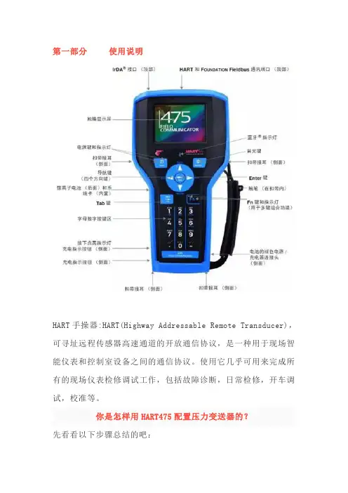
第一部分使用说明HART手操器:HART(Highway Addressable Remote Transducer),可寻址远程传感器高速通道的开放通信协议,是一种用于现场智能仪表和控制室设备之间的通信协议。
使用它几乎可用来完成所有的现场仪表检修调试工作,包括故障诊断,日常检修,开车调试,校准等。
你是怎样用HART475配置压力变送器的?先看看以下步骤总结的吧:1.开机,将手操器与仪表连接,选择HART2.通讯成功以后,选择Online(在线)当出现以下文字时,不要慌张,点YES就行3.具体操作,以川仪(EJA)为例。
改量程改位号、改单位回路测试(打点)调零点PS:在更改完数据后要选“SEND”发送给变送器HART475图形图像都说明了啥现场通讯器屏幕布局常用按钮使用下列按钮,可修改窗口上曲线图和图表的(以艾默生HART475为例)平移,触击按钮,选择图表或曲线图中的一点,拖动此点在窗口中反复地移动。
区域缩放,触击按钮,然后触击并拖动图表中的一点来创建放大的方框。
当您从窗口释放触笔后,图表将放大并适应此区域。
此控件仅可用于条形图表和曲线图。
放大,触击此按钮,从图表中心以固定比率放大。
再次触击,重复此操作。
缩小,触击此按钮,从图表中心以固定比率缩小。
再次触击,重复此操作。
重置,触击按钮,将图表或曲线图返回至原始主屏幕,取消您执行的任何平移或缩放操作。
下拉列表,触击此菜单,在不同的变量中选择,在图表上或曲线图的不同波形中高亮显示。
图形选项图像图像是设备的全屏幕照片。
图像可包含标识和多种图形,如容器。
要查看图像,选择菜单中的图像或绘图标签。
显示全屏幕图像。
要返回菜单视图,按任何键或触击触摸屏。
一些图像具有链接,可以运行方法或查看附加菜单。
如果图像具有链接,将在菜单中的图像或绘图标记旁出现箭头。
当打开图像后,使用向左键返回菜单、或按任意键启动方法或与图像或图纸关联的附加菜单。
如果链接未与图像关联,按任意键返回菜单。
HART475中文说明书
HART通信器是一种便携式的终端,它与采用HART通信协议的仪表一起使用,对其进行设定,更改和显示,它可监控输入/输出值和自诊断结果。
设定恒定电流的输出和调零。
当系统开动或维持操作时,只要把HART通信器接在4~20mA通信信号线上,就可以使用。
特点:■ 在线监控和通信通信期间,调制信号不会中断4~20mA DC信号■ 与采用HART通信协议的仪表可共用HART通信器能与采用HART通信协议的所有仪表一起使用■ 操作方便大显示屏幕(4行,每行18个字符),采用中文显示,用户看了一目了然,设定和更改方便■ 信息自诊断/保护功能自检查功能格式化密码保护低电压报警显示标准技术规格:装置的技术规格适用仪表:ROSEMOUNT1151 , ROSEMOUNT3051ABB日本富士YOKOGAWA EJA(带HART通信协议)等进口压力变送器DS-1151,DS-3351HK1151 , HK3151等国产智能压力变送器通信信号的连接:专用线缆,长1.1m(3.6ft)通信线:长度:1Km(0.62英里)(0.75~1.25mm2)负载电阻:250~600Ω负载电容:0.22uF以下负载电感:3.3mH以下与电源线的间距:15cm以上(避免平行走线)显示:128*64点阵液晶显示控制:触摸开关(4个方向键,19个功能键,一个电源开关)电源:4支1.2V可充电电池尺寸:180*80*54mm (长*宽*高)重量:700g功能说明基本功能:■ 设定、更改和显示各种参数,HART通信■ 恒定电流输出■ 调零附加功能:■ 格式化保护需要输入密码才能进行格式化■ 电池报警LCD显示的报警信息可提示电池电压偏低■ LCD对比度调节正常工作条件环境温度: -15~55℃存储条件:环境温度:0~50℃附件:■ 通信电缆:壹根,分别带一个弹簧夹。
■ 4只1.5V电池■ 手提包■ 说明书■ 250偶坶电阻EMC认可标准:EMI(辐射)—EN55011:1991hart475手操器 Rosemount罗斯蒙特HART475手操器 产品介绍 hart475手操器通讯器,艾默生过程管理的新型的475现场通讯器,是罗斯蒙特hart375手操器的改良升级型号,它即支持HART 通讯协议,也支持基金会现场总线通讯协议,并具有通用、可靠、便携、本安、易于升级等特点。
HART475手操器说明书(彩屏款)
目录第一节简介2第二节基本使用2安装电池组2启动和关闭2启动通信器3关闭3基本性能和功能3键区的使用4第三节电气连接方式5建立HART回路连接5查看在线菜单7第一节简介本仪表适合HART协议的智能变送器以及各类HART标准协议的流量仪表的通信操作,与HART275、HART375、HART475兼容,可通信1151,3051,EJA,ABB及其他HART协议的进口仪表,完全兼容国产的各种智能压力变送器以及带有HART协议的智能流量仪表。
第二节基本使用安装电池组1.将现场通信器正面朝下放在平稳的表面上。
2.按住电池后盖开关,将其推向■的一边打开后盖开关,将后盖揭开装进电池,当电池装好后再将后盖开关推向■的一边锁上开关。
(注意在揭开后盖时从缝隙处轻轻揭开,以免损坏后盖)启动和关闭该通信器使用5节5号干电池,使用前请确保:1.该通信器没有损坏2.电池组已安装好3.所有螺丝没有松动4.将通信器连接到回路,参见第三节:建立HART回路连接启动通信器按住开/关键,直到液晶屏点亮,表明装置已经工作。
开/关键位置可参见图2-1。
在启动期间,通信器将自动轮询检测HART回路设备,如果连接正常将显示被连接设备工位号及进入主菜单,您可以进行以下选择:关闭按住“开关”键半秒钟以上,松开按键,关机完成。
键区的使用开关键箭头导航键四个箭头导航键可便于您在菜单栏中移动,选择,进入或退出。
按右箭头导航键()可进入下一级菜单(同Enter 键),在操作界面为“确认”键功能或数据发送功能,对应屏幕显示右侧字符所表示的功能。
按左箭头导航键(口)可返回上一级菜单,在操作界面为“返回”或“取消”键功能,对应屏幕显示左侧字符所表示的功能。
在输入界面基本性能和功能HART 现场通讯接口液晶显示屏字母数字键区图2-1通讯器示意图① Power)用于现场通信器的启动或关闭。
JKL斗STLL开关键四个方向导航键所DawirrtdnlG4lfl r液晶背光B-^rtWFFDK时按下键为删除功能。
HART475手操器英文说明书

FIELD COMMUNICATORJIANGSU BOOST INSTRUMENT SCIENCE AND TECHNOLOGY CO.,LTDCHAPTER Ⅰ Introduction (2)CHAPTER Ⅱ Basic use (3)2.1 Field communicator basic performance and functions (3)2.2 Power Considerations (4)2.3 Key areas of use and instructions (5)CHAPTER Ⅲ menu online operation3.1 Test menu (6)3.1.1 Always poll (6)3.1.2 Ask before polling (7)3.1.3 Select the type (7)3.2 PRESS TRANS MAIN MENU (8)3.2.1 Process variables (8)3.2.2 Diagnostics and service (9)3.2.3 Characterization (11)3.2.4 Calibration (17)3.2.5 Display mode (19)3.2.6 General format (20)3.3 ELECTROMAGNETIC FLOWMETER MAIN MENU (20)3.4 VORTEX FLOWMETER MAIN MENU (20)3.5 FARGET FLOWMETER/ FLOAT LEV GAUGE MAIN MENU (20)3.6 METAL ROTAMETER MAIN MENU (20)3.7 GENERAL MAIN MENU (21)CHAPTER Ⅳ Troubleshooting (21)4.1 Description and remedy fault (21)4.2 Windows for warning (22)Appendix I (24)Appendix II (25)Appendix Ⅲ (31)CONTENTSCHAPTER Ⅰ IntroductionThank you for using HART475 Field Communicator, Communicator for the HART Communication protocol smart transmitter operation, and HART275, HART375,HART475 compatible with excellent compatibility, communication 1151,3051,EJA, ABB and flow aspects of the HART protocol imported instruments. Completely and yung made a variety of smart transmitters.The manual describes the basic use of field communication device, connection and operation in Content as well as troubleshooting and in the course should pay attention.Field Communicator using the HART475, please read the manual, In order to better play to the best performance of the product in use or maintenance of the product Before understanding of the appropriate content.Should the equipment needs repair, please contact our company. We will do our best to for you.The device is equipped with:a manual operatorBattery aPack aA chargerA communication cableManual aA 250 ohm resistorCHAPTER Ⅱ Basic use2.1 Field communicator basic performance and functionsCommunicatecableBatterydisplayDisplayFourkeysnavigationPV KeyEnterON/OFFAlphanumeric keypadCharger connectorLeft -right selectionkeyField Communicator2.2 Power ConsiderationsIn turn, ensure the following:* The Field Communicator is no mechanical damage* Battery is fully charged.* The Field Communicator to connect to the circuit (Figure 2-2) * String loop resistance of 250 ohms+··Power —+-Figure 2-2Start Field CommunicatorBefore starting to ensure that the device is fully charged. Start holding down the power key until To the bright LCD screen, a successful boot.CloseSuch as to close the Field Communicator, hold the key to open up their show off, shutdown complete.2.3 Key areas of use and instructionsOpen keyThe key is used to enable or disable the Field Communicator. Arrow navigation keysFour navigation arrow keys provide menu options. Press the right arrow navigation key to enter a menu of specific options. Press Left navigation key to return to the previous menu, up and down navigation keys can be cut down in the menu Change. In the character input mode digital down navigation keys can be used as a backspace key. EnterAfter entering the menu, you can modify the contents of the LCD's bottom Line will automatically display the "Edit" to modify the words For you press the Enter key, the change was successful.Alphanumeric keyboardCharacter numeric keypad to enter characters, numbers and other symbols, numbers, and he has Characters in both input modes, field communication device according to the need to select the appropriate input mode.To enter numbers, press the number directly to where the keys to enter characters, according to the word Character position on the keyboard, first pressA key, then press the characterkey is located. For example, to enter the character "A", the first Press the left selection key, then press the number 1 character keyboard.PV keyMonitoring real-time variable shortcuts, view real-time pressure, current, percentage, Temperature, frequency and other real-time variable. Digital input mode, the character, the key is invalid.CHAPTER Ⅲ menu online operation3.1 Detection menuHow to poll:2.Ask Bef PollFigure 3-13.1.1 Polling DetectionSelect the menu, Field Communicator polling numbers from the polling numbers from 0 to 15 followed by detection equipment, if detected, the device will automatically detect the transmitter and the station number(Figure 3-1-1), press the right navigation key to enter the device type selection menu (Figure3-1-2); if not Have detected the device does not detect the transmitter will appear warning.TRANS detected:TAG No[DS8001]Figure 3-1-13.1.2 Detection by poll numbersSpecified number of polling devices to detect, according to the up and down navigation keys Choose between 0 to 15 polling numbers, then press the right navigation key to start the test (test results If the same as Figure 3-1-1).3.1.3 Select Device Type1. Pressure Transmitter2 electromagnetic flowmeter3. Vortex Flowmeter4. Target Flowmeter / float level gauge5. Turn meter gold6 General menuSelect the type:2.Electromagnetic Flow meter3.Vortex Flowmeter4.Target Flowmeter / FloatLEV gauge5.Metal Rotameter6. General MenuWhen choosing the type of equipment must be selected according to the type of field device into a specific menu, if you select the type does not match the actual type, will cause an error. If the site becomes non-pressure equipment, electromagnetic, vortex, target-style, gold transfer device is connected into the general menu. Press the down navigation key to select the device type, then press the right navigation key to enter the selected device type detection, and enter the corresponding menu, if you select the type does not match with the test will be prompted.3.2 Pressure Transmitter Main MenuSubmenu1 Process Variable2 Configuration and testing3 Characterization4 Calibration Main menu:2.DIAG and Service 3.Characterization5 Display Modes6 common formatFigure 3-2-13.2.1 Process VariableReal-time display of pressure transmitter, the percentage of current, temperature and other parameters (Figure 3-2-2). Press the left navigation button for 3 seconds before the bounce out of real-time variable monitoring model.PRESS AO PC –0.2584.8205.127KpamA%TEMP 19.570 ℃3.2.2 Configuration and TestingDIAG and Service 2.Loop Test Submenu:1. Equipment Testing2. Loop test3. Basic Settings4. User range3.Basic setup Figure 3-2-3 3.2.2.1 Test equipmentTesting equipment status, if everything is normal, liquid crystal display "device normal", if wrong, will be a warning.3.2.2.2 Loop TestDetection of the D / A current output. First, a series ammeter in the circuit, and then type a 4-20mA current between the values into the transmitter, the transmitter will automatically output the current value type, if the type of value and ammeter display values are not equal, current fine-tuning to be done.3.2.2.3 Basic SettingsSubmenu:1. Unit2. Write Protect3. DampBasic Setup 2.Write Protect 3.Damping 4. Output5. Device Information6. Polling numbersFigure 3-2-4 UnitChange the primary variable units and display units. Provide MPa, Kpa, Pa, InH2O, InHg, psi, g / cm ², kg / cm ², FtH2O, torr,ATM, mmH2O, mmHg, Bar, mBar these 15 units. When the unit of measure on behalf of the Not recognize the number will automatically display "No" means that the unit "unknow". Repair Change methods, see the menu tree.Write ProtectRead-write device protection status, when the write-protected, the transmitter can not change the internal data. DampRead-write device damping coefficient (rounded to three decimal places). Seconds.OutputRead-write device output. Divided into linear, square root, and the unknown. The default is linear.Device InformationRead and write tag number, date, descriptor, message, final assembly numberPolling numbers3.2.2.4 User rangeUser Range2.Provide pressureFigure 3-2-5Keyboard inputSelect this menu, the first prompt sensor range, then enter the range of the setup menu, press the down navigation key to select zero or range, then enter the user needs to set the value (rounded to three decimal places), then press the right navigation key into the transmitter.Sensor Range L –180.000KPa H 180.000KPa User RangeL –180.000KPa H 180.000KPaFigure 3-2-6 Figure 3-2-7Provide pressure valuesPressure on the current value with the transmitter zero and span settings, press the up and down navigation keys, press the right navigation key to confirm.Provide Pressure2.RangeFigure 3-2-83.2.3 CharacterizationSubmenu:1 .Sensor trim2. Sensor measuring range3 user range4.K coefficient5 Formatting Characterization 2.Sensor range 3.User range6 small-signal removal7 Device Address8. Data Backup9. Data RecoveryThe menu will seriously affect the operation of the transmitter to work and accuracy, so enter this menu, you need to enter the authentication password (Figure 3-2-10).Please input password:******Figure 3-2-10The default password is: 6666663.2.3.1 Sensor trimSensor Trim2.Low Range Trim3.High Range TrimFigure 3-2-11Zero trimAfter the pressure transmitter with 0 to select this operation, the transmitter automatically adjust zero.Low fine-tuningTo increase low-pressure transmitter (in KPa), type the applied pressure values (rounded to three decimal places), thetransmitter automatically corrected, so that the output value of the applied pressure.High-end fine-tuningTo the transmitter plus high pressure (in KPa), type the applied pressure values (rounded to three decimal places), the transmitter automatically corrected, so that the output value of the applied pressure.3.2.3.2 Sensor RangeSensor Range2.Madify rangeFigure 3-2-12Select the rangeFirst select the type of sensor, and then select the range of the sensor code, then press the Enter key into the transmitter. (Figure 3-2-13,3-2-14)Sensor type Range Code[DP ][5]Figure 3-2-14Figure 3-2-13Modify RangeFirst select the range sensor code, then enter the code in the range of the scale. Note: The input pressure is measured in Pa, can only enter a positive integer. Change and then select the sensor range.3.2.3.3 User rangeKeyboard inputSelect this menu, the first prompt sensor range, then enter the range of the setup menu, press the up and down navigation key to select zero or range, then enter the user needs to set the value (rounded to three decimal places), enter and press the right navigation key to send into the transmitter.Sensor Range User RangeL –180.000KPa H 180.000KPa L –180.000KPaH 180.000KPaFigure 3-2-16Figure 3-2-15Provide pressure valuesPressure on the current value with the transmitter zero and span settings, press the up and down navigation keys, the right navigation key to confirm.pressProvide Pressure2.Range3.2.3.4 K factorLow-end need to be done, do high-end.K-factor2.High RangeFigure 3-2-18Low RangeAdd 0 to the pressure transmitter, type 0 in the increase of pressure, press the right navigation key into the transmitter, the transmitter automatically adjust the k-factor low.High RangeAdded to the positive terminal of a pressure transmitter (close to or equal to the physical range), the pressure increases the pressure must be greater than 0, type in the increase of pressure values (rounded to three decimal places, units KPa), press the right navigation key into the transmitter device, the transmitter automatically adjusts the k-factor high.Note: K factors must be operated in positive pressure conditions, and the input unit KPa.3.2.3.5 FormatFull-scale formatNote: This action will seriously affect the accuracy of the transmitter, the user is best not to make their own format.How-to: give added pressure transmitter (pressure points must be positive from the negative pressure up to maximum pressure), then enter the applied pressure (Figure 3-2-19, note: do the negative pressure side formatting , the input pressure to a minus sign in front.), then press the right navigation key to format it, after a successful return to the next point format, an unsuccessful return warning.All of range:01PRESS:[ ]PaFigure 3-2-19InterpolationAfter the ultra-poor calibration point format.Note: This action will seriously affect the accuracy of the transmitter, the user is best not to make their own format.How-to: give added pressure transmitter, and then enter the increase of pressure. (Note: do the formatting in the negative pressure side, the input pressure to a minus sign in front). Press the right navigation key, the interpolation done at this time point measured the pressure should be basically equal to the applied pressure.InterpolationPRESS:[ ]PaFigure 3-2-203.2.3.6 Small-signal removalThis function is to eliminate the zero drift. Enter the number of users than the extreme range.3.2.3.7 Device addressView a device's address. Device address is the unique identification number the smart board.3.2.3.8 Data BackupData backup: the value of the current user scale and format all the data back to FLASH the database, this function is to facilitate data recovery after a mistake. Click the menu "Backup" button3.2.3.9 Data RecoveryData Recovery: The instrument factory, manufacturers have the formatting operation on the instrument, and the correct data formatted to do a backup, misuse of the instrument when the user does not work, you can use the "Data Recovery" function of its error Content removal operation, and re-manufacturers will re-initialize the backup data is written instrument, easy instrument to restore the original data. Click the menu "Data Recovery" button.3.2.4 CalibrationCalibrationSubmenu2.Output Trim1 Sensor trim2 Output TrimFigure 3-2-213.2.4.1 Sensor trimSensor Trim2.Low Range Trim3.High Range TrimZero trimAfter the pressure transmitter with 0 to select this operation, the transmitter automatically adjust zero.Low fine-tuningTo increase low-pressure transmitter (in KPa), type the applied pressure values (rounded to three decimal places), the transmitter automatically corrected, so that the output value of the applied pressure.High-end fine-tuningTo the transmitter plus high pressure (in KPa), type the applied pressure values (rounded to three decimal places), the transmitter automatically corrected, so that the output value of the applied pressure.3.2.4.2 Output TrimOutput fine-tuning needs to be a precision ammeter in series to the circuit, into the fine-tuning, the LCD will prompt access ammeter, the current fine-tuning exit, the LCD will prompt recovery circuit.Warning:Please access circuitammeter!Figure 3-2-234mA current fine-tuningChoose 4mA current fine-tuning, the output should be 4.000mA, if the ammeter shows the value is not equal to 4.000mA, select "No", an input box, type the ammeter showsthe input box value (rounded to three decimal places), then press right navigation key to enter the current value into the transmitter, the transmitter will automatically calibrate the current output, the output of 4.000mA, if a less than satisfactory results, repeat this operation.(Note: The meter accuracy should be higher than the output precision of the table)Output Trim2. Trim DAC GainFigure 3-2-2420mA current fine-tuning4mA current methods of operation and fine-tuning the same. 3.2.5 Display Mode1.%Select this mode, the transmitter displays the percentage.ER SETSelect this mode, the transmitter displays the user settings. ER SET &%Select this mode, the transmitter displays the percentage of user settings and are displayed alternately every 4S.4.INPUT PRESSSelect this mode, the transmitter only the input pressure.5.INPUT PRESS &%Select this mode, the transmitter displays the percentage of input pressure and alternating every 4S.Display Mode2.USER SET3. USER SET&%Figure 3-2-253.2.6 General FormattingGeneral Format: (known as three, five-point format)This menu requires a password to enter the default password is 666666.(1) Select the instrument type and range of code to determine the instrument's physical range.(2) in the common format into the format, the original plate for 1151 current 22mA, the order of the physical range of 0%, 60%, 100% three-point format, or 0%, 60%, 100%, -60%, 100% five-point format. Communication device according to the first line shows the calculation of the percentage range of physical pressure, the pressure and the input Fill pressure (in Pa), right-click until the pressure stabilized first sent.(3) operation is successful, display the percentage of the next point, to continue or exit.Operation failed (such as the pressure increases the pressure and display the corresponding percentage difference too large to return to this point redo. Done 100% in three-point format according to exit after completion of five-point format at 100% done automatically exit. withdrawal of current from 22mA into a measurement of current.3.3 Electromagnetic Flowmeter Main MenuSee photos3.4 Vortex FlowmeterSee photos3.5 Target Flowmeter / float level gaugeSee photos3.6 meter gold transferSee photos3.7 Common main menuSee photosRemarks:The handheld contains vortex flowmeter, the target flowmeter, flow meter gold turn, Common menu and menu operation is similar to the electromagnetic flow meter, this is not setting them in, with Please refer to the distribution of body attached page menu menu tree operation.CHAPTER Ⅳ Troubleshooting4.1 Introduction and troubleshooting faultsIt does not really startIf in the course can not be switched, that can not start the Field Communicator, First check the battery. Should the battery power is still not start, there may be on-site Communication device to open the key is damaged. (Note: Please do not use the process of firm Hard thing to touch the buttons Field Communicator film to avoid damage. )Communication or communications are not interrupted If there is no communication on the first check HART field device loop and voltage. Almost all field devices have at least 4mA and 12VDC to Victoria maintain normal operation.Check the loop impedance, to see whether the access loop 250 ohm external Impedance. Access to 250 ohm resistors, will lead 250 ohm resistor at both ends of the access. And then view the communication is normal.Check the terminal and HART communications cable is damaged.HART communication by the control system interference. At this point stop control system HART communication, recognition and communication between the field device communication.4.2 Tips interfaceLow battery warningWhen the battery voltage is low, top right of the LCD display will flash a battery-shaped pattern.TAG No(DS8001)OnlinePRESS AO0.0064.000KpamAFigure 4-2-1Communication Failure WarningWhen the Field Communicator to the transmitter with the communication failure warning (Figure 4-2-2).Warning:Communication interruption!Check the equipmentFigure 4-2-2Date Input ErrorAllows you to enter a date range January 1, 1900 to December 31, 2155, when the input is not in the range of dates, enter the error message will appear (Figure 4-2-3), note the date input format xxxx xx xx day in May.Date entered incorrectlyFigure 4-2-3Data entry errorsWhen the input parameter is incorrect when the prompt appears, such as the removal of only a small signal input is an integer, if you enter a negative number, an error message will appear (Figure 4-2-4).Entered incorrectly!Appendix I: General menu list of unit typesNo. Unit No. Unit No.3 Unit No.4Unit1 InH2O2 InHg mmH2O mmHg5 9psikg/cm2ATML/S6 barPa7 mbarkPa8 g/cm2torr10141811151912162013 17 L/minm3/sm3/h℃m/smv21 25 29 33Ωm3minv22263034Hzm23273135mAcmh24283236Lmm%spH kg MT37 41 45lb 384246STg/h394347LT 404448g/skg/minlb/s g/minkg/hkg/sMT/min MT/h49 lb/min 50 lb/ h 51 ST/min 52 ST/h53 57 61 65 69 LT/hkg/lL/hKJ5458626670g/cm3g/l5559636771kg/m3m/h5660646872g/mlm3/minKJ/hNm3/hMJ/hMPaNm3/minMJ GJ/h GJ None NoAppendix II: various types of equipment menu tree Pressure Transmitter menu tree:Electromagnetic Flowmeter menu tree:Vortex Flowmeter menu tree:Target Flowmeter / float level gauge menu tree:Gold transfer meter menu tree:Common menu tree:Appendix 3: GlossaryAlphanumericAlphanumeric character set, often including other character sets, such as punctuation marks.Device configurationDefine the physical properties and operating characteristics of the device parameters. Does not include dynamic data.Device DescriptionWritten in the HART Foundation fieldbus devices instruction set, the device description language of the host application and the HART or FOUNDATION fieldbus device communication parameters, and methods of instruction are defined.Field EquipmentIn addition to HART digital communication signal, the field device can generate or receive analog signals.HART devicesUsing the HART protocol for information communication equipment.HART LoopOne communication network, the master and slave devices are HART smart or HART compatible devices.HART protocolAddressing a high-speed remote communications protocol converter. One for the digital add-type 4-20mA communications and intelligent field devices, industry-standard protocols.PollOne kind of query the network in order to determine the method that the device online.。
475手操器使用教程
475手操器使用教程引言:475(HART)手操器是一种用于操作和配置HART(Highway Addressable Remote Transducer)通讯协议的设备。
本文将详细介绍475手操器的使用方法和步骤,帮助读者快速熟悉和掌握该设备。
一、查找设备1.打开475手操器的电源,待其启动完毕后,进入主界面。
2. 在主界面上方,有一个“Find”按钮,点击该按钮进入设备查找模式。
3.在设备查找模式下,手操器会扫描附近的HART设备,当附近有设备可用时,手操器会显示在屏幕上。
如果屏幕上没有显示任何设备,则表示附近没有可用的HART设备。
4.点击手操器屏幕上显示的设备,即可选中该设备。
二、连接设备1. 选中设备后,点击手操器界面下方的“Connect”按钮,手操器将与所选设备建立连接。
2.当手操器与设备成功建立连接后,手操器界面将显示设备的基本信息,如设备名称、设备型号、设备状态等。
三、读取设备参数1.在设备连接成功后,手操器会自动读取设备的基本参数信息,并显示在手操器界面上。
2. 若要读取更多的设备参数信息,可以点击手操器界面上的“Read”按钮。
3.手操器会根据设备的配置,读取相应的参数信息,并显示在手操器界面上。
四、配置设备参数1.在手操器界面上,可以看到设备的各项参数信息。
2.若要修改一些参数,可以点击该参数所在的位置,并输入新的数值。
确保输入正确后,点击确认按钮进行参数修改。
3.在修改参数后,手操器会自动向设备发送新的参数配置命令,设备会根据手操器的配置进行相应的设置。
五、保存配置1.在参数修改完成后,为确保配置的持久性,需要将配置保存到设备中。
2. 点击手操器界面下方的“Save”按钮,手操器会将当前的配置信息保存到设备中,并显示保存成功的提示信息。
六、退出连接1.在配置完成后,需要断开和设备的连接。
2. 点击手操器界面下方的“Disconnect”按钮,手操器将与设备断开连接。
3.在断开连接后,手操器将返回到主界面,准备进行下一次操作。
475手操器中文使用手册
2简介3爆炸可能会导致严重伤害或死亡:在有爆炸危险的环境中使用时,必须遵守相关的本地、国家和国际标准、规范和规程。
请查阅《475型现场通讯器用户手册》中的“参考信息”和“产品认证”部分,以了解有关安全使用的限制规定。
触电可能会导致严重伤害或死亡。
此设备符合 FCC 规范的第 15 部分。
设备操作应符合以下两个条件:(1) 本设备可能不会产生有害干扰,以及 (2) 本设备必须接受任何接收到的干扰,包括可能会导致非预定操作的干扰。
©2009 艾默生过程管理。
保留所有权利。
HART 为 HART 通信基金会的注册商标。
F OUNDATION为现场总线基金会的商标。
IrDA 为红外数据协会的注册商标。
Bluetooth 为 Bluetooth SIG, Inc. 的注册商标。
AMS Suite 为艾默生电气公司的注册商标。
艾默生标志为艾默生电气公司的商标和服务标志。
所有其他商用标志的所有权归其各自的所有者。
简介《475型现场通讯器使用入门指南》提供了 475型现场通讯器的基本操作指南、注意事项和设置信息。
它不包括有关配置、诊断、维护、保养、故障排除或本质安全 (IS) 安装的详细说。
有关更多说明,请参阅资源 CD 里的《475型现场通讯器用户手册》或访问。
475型现场通讯器支持 HART 和 F OUNDATION现场总线设备,使您可以进行现场配置或排除故障。
电子设备描述语言 (EDDL) 技术使得 475型现场通讯器能与大量不同生产商的设备进行通讯。
4475 型现场通讯器概述475 型现场通讯器概述便携式 475 型现场通讯器包括一个彩色 LCD 触摸屏、一块锂离子电池(电源模块)、一个 SH3 处理器、存储组件以及集成通讯与测量电路。
当使用 475 型现场通讯器与设备进行通讯时,请遵守当地适用的所有标准和程序。
不遵守这些标准和程序可能会导致设备损坏和/或人身伤害。
请理解并遵守本手册中的各项内容。
hart475手操器中文说明书
目录第一章简介⋯⋯⋯⋯⋯⋯⋯⋯⋯⋯⋯⋯⋯⋯⋯⋯⋯⋯⋯⋯2第二章基本使用⋯⋯⋯⋯⋯⋯⋯⋯⋯⋯⋯⋯⋯⋯⋯⋯⋯⋯32.1 现场通讯器的基本性能和功能⋯⋯⋯⋯⋯⋯⋯⋯⋯⋯⋯⋯⋯⋯32.2 开机注意事项⋯⋯⋯⋯⋯⋯⋯⋯⋯⋯⋯⋯⋯⋯⋯⋯⋯⋯⋯⋯⋯42.3 键区的使用和说明⋯⋯⋯⋯⋯⋯⋯⋯⋯⋯⋯⋯⋯⋯⋯⋯⋯⋯⋯5第三章在线操作菜单⋯⋯⋯⋯⋯⋯⋯⋯⋯⋯⋯⋯⋯⋯⋯⋯63.1 检测菜单⋯⋯⋯⋯⋯⋯⋯⋯⋯⋯⋯⋯⋯⋯⋯⋯⋯⋯⋯⋯⋯⋯⋯6 3.1.1 轮询检测⋯⋯⋯⋯⋯⋯⋯⋯⋯⋯⋯⋯⋯⋯⋯⋯⋯⋯⋯⋯⋯6 3.1.2 按轮询号检测⋯⋯⋯⋯⋯⋯⋯⋯⋯⋯⋯⋯⋯⋯⋯⋯⋯⋯⋯7 3.1.3 选择设备类型⋯⋯⋯⋯⋯⋯⋯⋯⋯⋯⋯⋯⋯⋯⋯⋯⋯⋯⋯73.2 压力变送器主菜单⋯⋯⋯⋯⋯⋯⋯⋯⋯⋯⋯⋯⋯⋯⋯⋯⋯⋯⋯8 3.2.1 过程变量⋯⋯⋯⋯⋯⋯⋯⋯⋯⋯⋯⋯⋯⋯⋯⋯⋯⋯⋯⋯⋯8 3.2.2 组态与测试⋯⋯⋯⋯⋯⋯⋯⋯⋯⋯⋯⋯⋯⋯⋯⋯⋯⋯⋯⋯9 3.2.3 特征化⋯⋯⋯⋯⋯⋯⋯⋯⋯⋯⋯⋯⋯⋯⋯⋯⋯⋯⋯⋯⋯⋯12 3.2.4 校准⋯⋯⋯⋯⋯⋯⋯⋯⋯⋯⋯⋯⋯⋯⋯⋯⋯⋯⋯⋯⋯⋯⋯19 3.2.5 显示模式⋯⋯⋯⋯⋯⋯⋯⋯⋯⋯⋯⋯⋯⋯⋯⋯⋯⋯⋯⋯⋯21 3.2.6 通用格式化⋯⋯⋯⋯⋯⋯⋯⋯⋯⋯⋯⋯⋯⋯⋯⋯⋯⋯⋯⋯223.3 电磁流量计主菜单⋯⋯⋯⋯⋯⋯⋯⋯⋯⋯⋯⋯⋯⋯⋯⋯⋯⋯⋯233.4 涡街流量计主菜单⋯⋯⋯⋯⋯⋯⋯⋯⋯⋯⋯⋯⋯⋯⋯⋯⋯⋯⋯233.5 靶式流量计 /浮筒液位计主菜单⋯⋯⋯⋯⋯⋯⋯⋯⋯⋯⋯⋯⋯233.6 金转流量计主菜单⋯⋯⋯⋯⋯⋯⋯⋯⋯⋯⋯⋯⋯⋯⋯⋯⋯⋯⋯233.7 通用主菜单⋯⋯⋯⋯⋯⋯⋯⋯⋯⋯⋯⋯⋯⋯⋯⋯⋯⋯⋯⋯⋯⋯23 第四章故障排除⋯⋯⋯⋯⋯⋯⋯⋯⋯⋯⋯⋯⋯⋯⋯⋯⋯⋯244.1 故障介绍和排除方法⋯⋯⋯⋯⋯⋯⋯⋯⋯⋯⋯⋯⋯⋯⋯⋯⋯⋯244.2 提示界面⋯⋯⋯⋯⋯⋯⋯⋯⋯⋯⋯⋯⋯⋯⋯⋯⋯⋯⋯⋯⋯⋯⋯25附一⋯⋯⋯⋯⋯⋯⋯⋯⋯⋯⋯⋯⋯⋯⋯⋯⋯⋯⋯⋯⋯⋯⋯⋯27 附二⋯⋯⋯⋯⋯⋯⋯⋯⋯⋯⋯⋯⋯⋯⋯⋯⋯⋯⋯⋯⋯⋯⋯⋯281第一章简介感谢您使用本现场通讯器,本通讯器适合 HART 协议智能变送器的通讯操作,与 HART275 、HART388 、 HART375 兼容,具有极好的兼容性,可通讯 1151,3051,EJA,ABB 及流量方面的HART 协议的进口仪表。
hart475手操器中文说明书32774
目录第一章简介 (2)第二章基本使用 (3)2.1现场通讯器的基本性能和功能 (3)2.2开机注意事项 (4)2.3键区的使用和说明 (5)第三章在线操作菜单 (6)3.1检测菜单 (6)3.1.1轮询检测 (6)3.1.2按轮询号检测 (7)3.1.3选择设备类型 (7)3.2压力变送器主菜单 (8)3.2.1过程变量 (8)3.2.2组态与测试 (9)3.2.3特征化 (12)3.2.4校准 (19)3.2.5显示模式 (21)3.2.6通用格式化 (22)3.3电磁流量计主菜单 (23)3.4涡街流量计主菜单 (23)3.5靶式流量计/浮筒液位计主菜单 (23)3.6金转流量计主菜单 (23)3.7通用主菜单 (23)第四章故障排除 (24)4.1故障介绍和排除方法 (24)4.2提示界面 (25)附一 (27)附二 (28)第一章简介感谢您使用本现场通讯器,本通讯器适合HART协议智能变送器的通讯操作,与HART275、HART388、HART375兼容,具有极好的兼容性,可通讯1151,3051,EJA,ABB及流量方面的HART协议的进口仪表。
完全兼容国产的各种HART协议智能变送器。
该手册介绍了现场通讯器基本的使用、连接和操作方面的内容以及故障的排除和在使用过程中应该注意的事项。
在使用本现场通讯器之前,请阅读该该操作手册,为了更好发挥该产品的最佳性能,在使用或维修本产品之前,请深入掌握相应的内容。
如若设备需要维修,请联系我们公司。
我们将竭尽所能为您服务。
该设备配备:手操器一台电池(机内)一块包一个充电器一部通讯线缆一条操作手册一本250欧姆电阻一支第二章 基本使用2.1 现场通讯器的基本性能和功能现场通讯器示图开/关键数字字母按键区显示区PV 键 左中右选择键四个导航键 确认键 充电器接口通讯电缆电池显示2.2开机注意事项在开机前,请确保以下几点:·该现场通讯器没有物理机械损坏 ·电池已充满电。