
西屋VCW12样本2018.8.6
VCW系列12kV固封极柱真空断路器美国西屋电气西屋电气公司(Westinghouse Electric Corporation)。
1886年1月8日,由G.威斯汀豪斯在美国宾夕法尼亚州创立。
总部设在宾夕法尼亚州匹兹堡市。
1889年时曾改名西屋电工制造公司(Westinghouse Electric Manufacturing Company),1945年10月改用现名。
西屋电气公司在世界26个国家和地区设有 250家工厂,现有职工125000人,持股人135000人。
其主要业务领域涉及发电设备、输变电设备、用电设备和电控制设备、电子产品等门类共4000多种产品。
其中,以发电设备、输变电设备尤具特色,从公司成立以来,一直享有世界声誉。
西屋电气公司设有56个研究单位,有研究人员6792人,其中西屋研究发展中心有职工1750人(专业人员650名,其中博士325名)。
公司还设立了“西屋公司青少年天才发明奖”,以鼓励高中学生的发明创造。
1945年西屋电气公司曾与中国资源委员会签定协议接受中国70多名科技人员前去学习、培训。
其中有褚应璜、丁舜年等,他们中很多人成为中国电工发展的骨干力量。
80年代,中国从西屋电气公司引进30万千瓦和60万千瓦的汽轮机组,分别安装在石横电厂和平圩电厂。
自2009年9月起,美国西屋旗下的一系列种类广泛的电气产品及智能家居产品,重新回到了中国,为中国的发展与进步提供创新产品服务。
企业简介影响人类电气及应用科技进程的重大事件:1886年建立了第一座交流发电厂1891年建立第一条交流高压输电线路1895年生产第一台水轮发电机(尼亚加拉瀑布5000千瓦);照亮法布罗城,结束交直流电优势世纪之争,标志世界交流电应用正式开始1900年制造出首台汽轮发电机,标志世界通用汽轮机组的开始1937年制造出首台工业用核粒子加速器1955年试制成首台超临界、二次再热汽轮发电机1960年成功制造首台500千伏六氟化硫断路器1969年制造美国宇航局太空视频系统,视频发回地球1988年首个40KA 纵磁真空泡开发成功1994年推出世界上最大,效率最高的501G燃气轮机目录产品简介产品应用技术参数 (05)外形尺寸 ..................................06二次接线 ..................................08选型表 . (10)概况作为世界电气现代化进程最重要的开创者之一,西屋(Westinghouse)130年以来一直以电气行业的创新领导者引领技术的发展,推进了人类现代化文明。
从1945年开始西屋就支持并参与了中国的电气现代化进程,参与培养了褚应璜、丁舜年等中国电气发展的顶尖骨干力量;今天西屋带回中国VCW 中压真空断路器,产品采用西屋先进的真空灭弧室与固封绝缘制造技术,匹配智能化控制系统;90年真空技术的全新应用,对130年世界级创新做出了新的诠释,为用户提供全球共享的先进解决方案。
概况使用条件..............................01执行标准..............................01产品特色..............................02固封极柱..............................02机构..................................02VCW 真空断路器.. (02)选型指南..............................03结构及辅件............................03可选配件 (04)事业内容 I 工业、家庭用电气设备制造及销售主要产品 I 微型断路器 塑壳断路器真空断路器 框架断路器中低压开关柜 变压器高低压母线槽 电容电抗产品简介(A)38003150A34002500A300026002000A22001600A180014001250A1000630A6004000A及以上需强制风冷周围温度2030405060℃使用场合:VCW 系列真空断路器采用西屋先进的电气研发经验及制作工艺,可广泛用于电厂、电网、化工、冶金、新能源、基础设施配套等用电领域。
VCW 系列真空断路器适用环境:■ 抗震烈度:≤8度■ 海拔高度:≤4500m*(常规产品1000m 及以下,高海拔产品需订货时说明)■ 环境温度:-25~+40℃*(常规最低温度-15 ℃,-25 ℃ 需订货时说明)■ 环境湿度:日平均相对湿度≤95% 月平均相对湿度≤90% 日水蒸气压平均值≤2.2kPa 月水蒸气压平均值≤1.8kPa■环境污秽等级:≤2级(GB/T5582)■ 二次回路电磁干扰幅值≤1.6kV执行标准:■ GB1984-2014《高压交流断路器》■ GB/T11022-2011《高压开关设备和控制设备标准的功用技术要求》■ DL/T402-2007《高压交流断路器订货技术条件》■ DL/T593-2006《高压开关设备和控制设备标准的功用技术条件》■ JB/T3855-2008《高压交流真空断路器》■ IEC62271-100-2012《高压交流断路器》■ IEC60694-2002《高压开关设备和控制设备标准的通用规范》海拔修正系数Ka=eH-海拔(米) m-简化固定值=1对于工频、雷电冲击和相间操作冲击电压=0.9对于纵绝缘操作冲击电压 =0.75对于相对滴操作冲击电压温度降容对照表海拔降容对照表产品特色真空灭弧室■ 触头材料:采用国际先进原材料:50%:50%,cu、cr 烧结;■触头型式:纵磁场杯状触头,优点为开断大短路电流截流值低至2A。
■ 抽真空工艺:采用一次封排工艺■ 真空度:1*10-5Pa介质恢复强度高,低漏气率,使用寿命最长可达30年■ 接触电阻:仅组装式用真空灭弧室的70%,降低固封产品的发热量■ 机械强度高:机械寿命>5万次■电气性能:开断绝缘恢复性强,大大降低重燃及TRV 击穿固封极柱■ 材料:先进工艺及材料,吸湿性优于绝大多数热塑型电气工程塑料■ 工艺:APG 凝胶工艺■局放:超过GB 标准,产品最低<2PC■绝缘性能:爬电距离超过GB 及IEC标准,裕量高■ 强度:远大于组装式,由于整体浇筑,各部件联结导体形成整体,不会因震动而出现接触电阻超标事件■ 环境影响:因为密闭式固封,避免粉尘、潮气、气候、影响VCW 真空断路器■ 满足IEC、GB、DL 标准要求■结构牢固,使用寿命长,最高机械寿命>50000次■ 满容量分断次数最高50次■ 额度短路开断电流DC 分量≥50%■更小的开极距离,更小的冲击,确保降低真空漏气率增加机构寿命■二次附件具备EMC 电磁干扰防护,防止误动作■快速负载切换运行方式,用于0-0.3s-co-3min-co 自动重合闸■ 适用电容器开关操作,开断背对背电容器组不超过400A,单个电容器组不超过630A;并联电容器允许接通最大峰值10KA机构■ 采用增强型机构设计,结构更稳定,部件更少■ 采用特色自润滑轴承,保证机构50000次以上的运行免维护■ 采用特色的表面钝化处理,确保机构的使用工况及耐用范围■ 近百年的制造工艺,确保产品的稳定与先进■ 因采用优质触头材料截流值最低至2A,开断空载变压器不会产生危险过电压适用架空线路和电缆的操作,不会出现延弧导致过电压■ 对高压电机的启动过程开断,建议不高于600A 高压电机,采用浪涌吸收器防止过电压■ 产品具有完善的五防连锁可与KYN28等主流柜体配合■ 如断路器直接使用在保护发电机时,因瞬态过电压高于普通工况的10倍以上,需采用发电机保护用断路器■ 直流分量DC%,最高>70%产品简介产品简介0102地底盘车合闸按钮二次航空插座分合闸指示固封极柱储能指示分闸按钮计数器活门连锁储能手柄安装方式:W:抽出式 F:固定式额定电流(A) :630、1250、1600、2000、2500、3150、4000额定短路开断电流(kA):25、31.5、40、50电压(kV)产品型号W产品应用51627384910操动机构与闭锁电磁铁的技术数据*:选型表见末页产品应用产品应用过电流脱扣器防跳继电器合闸闭锁欠电压脱扣器操作手柄名称:合闸闭锁作用:防止误合闸装置参数:AC/DC- 110V、220V名称:欠压脱扣器(失压脱扣器)作用:主回路欠压保护动作,属于断路器主动保护器件参数:AC110V/AC220V 可选使用方法:通过主回路PT 二次侧供电,欠压即动作,使断路器分闸名称:防跳继电器作用:防止合闸线路故障导致的合闸跳跃使用方法:综保与断路器均有防跳,则需要取消其中一个,本断路器的取消方法详见接线图名称:过流脱扣器作用:主回路过流保护动作,属于断路器主动保护器件参数:2.5A、3A、5A 可选使用方法:通过主回路CT 二次侧供电,过流即动作,使断路器分闸名称:底盘车操作手柄作用:底盘车进出操作装置0304注:(1)额定电流4000A 时开关柜需带强制风冷技术参数电寿命与开断电流对应表技术参数手车式05开断电流Isc(kA)12kV, 1250A, 25kA ......开断电流Isc(kA)12kV,1250A ~4000A,40kA开断电流Isc(kA)12kV,1250A ~4000A,50kA开断电流Isc(kA)12kV, 3150A, 31.5kA......开断次数N开断次数N开断次数N开断次数N二次接线S9:位置辅助开关(工作位置时)HQ:合闸线圈R0-R1:电阻S8:位置辅助开关(试验位置时)TQ: 分闸线圈V0~V4:整流器(直流时可取消)S4:闭锁电磁铁的辅助开关M:储能电机k0:机构内部防跳继电器(*可选)S1~S3:储能微动开关Y7-Y9:间接式过流脱扣线圈(*可选)QF:辅助开关Y1:合闸闭锁电磁铁(*可选)二次接线手车式08A10A11B9B10A8A7A6B8B7B6A9G1L2T4S1-13G2A5A3A4B4B3B2A2A1B1C73E12C51C54C52B5PCBE11T2H2C11H1S2-21D11D12T25T31A12A10A11B9B10A8A7A6B8B7B6A9G1L2T4S1-13G2A5A3A4B4B3B2A2A1B1C73E12C51C54C52B5PCB电机回路过流脱扣(A)相过流脱扣(C)相过流脱扣(B)相合闸回路闭锁回路分闸回路说明:1.订货时须注明是否带防跳,若确定需取消防跳装置,则必须把B4、B5断开。
2.图示为断路器处于试验位置、未储能、分闸状态。
3.当操作电源为直流时,须保证虚线框中极性一致,电机按图示极性要求接线。
CNAS-CL01-A008检测和校准实验室能力认可准则在电磁兼容检测领域的应用说明
检测和校准实验室能力认可准则 在电磁兼容检测领域的应用说明
Guidance on the Application of Testing and Calibration Laboratories Competence Accreditation Criteria in the
2018 年 03 月 01 日发布
2018 年 09 月 01 日实施
CNAS-CL01-A008:2018
第 4 页 共 202 页
检测和校准实验室能力认可准则 在电磁兼容检测领域的应用说明
1 范围
本文件是 CNAS 根据电磁兼容(EMC)检测领域的专业特点制定的特定领域应 用说明,适用于电磁兼容检测领域。本文件主要是针对实验室质量和能力要求所 做出的进一步说明,内容没有包含环境保护和安全方面的内容。对在非固定场所 进行的检测活动,应参照 CNAS-CL01-G005《检测和校准实验室能力认可准则在 非固定场所检测活动中的应用说明》的相关要求。
2018 年 03 月 01 日发布
2018 年 09 月 01 日实施
CNAS-CL01-A008:2018
第 2 页 共 202 页
附录 M(规范性附录)领域代码:1215 ..............................................................................89 附录 N(规范性附录)领域代码:1216 ............................................................................101 附录 O(规范性附录)领域代码:1217 ............................................................................112 附录 P(规范性附录)领域代码:1218、1219 .................................................................123 附录 Q(规范性附录)领域代码:1220 ............................................................................143 附录 R(规范性附录)领域代码:1221 ............................................................................144 附录 S(规范性附录)领域代码:1222 ............................................................................147 附录 T(规范性附录)领域代码:1223 ............................................................................149 附录 U(规范性附录)领域代码:1224 ............................................................................151 附录 V(规范性附录)领域代码:1225 ............................................................................155 附录 W(规范性附录)领域代码:1226 ............................................................................166 附录 X(规范性附录)领域代码:1227 ............................................................................178
Fisher ET系列直通阀(中文)

产品样本
51.1:ET 2011 年 4 月
特点
D 符合《清洁空气法案》—ENVIRO-SEAL 填料系 统(图 10 和图 11)提供了改良的阀杆密封,有助于 防止过程流体流失。ENVIRO-SEAL 填料系统有动态 加载的 ULF 石墨填料或双填料供选择,降低了填料维 护成本。
D 拥有持久关断性能的 PTFE 阀座—标准阀座结构 的受控压缩能力可以保护金属密封和密封压环(图 2) 之间的 PTFE 密封环。在正常工作过程中,只有流动 介质会接触 PTFE 密封环的边缘。可通过支撑环或弹簧 保持的关断性能,让阀芯密封环压在阀笼上(图 2)。
带 Cavitrol III 二级阀笼的 ET 阀门
金属
V
ET 和 EAT,带 TSO(严密关断)阀内件 (CL125 磅级至 CL600 磅级)
EAT,带 TSO(严密关断)阀内件 (CL125 磅级至 CL600 磅级)
可更换的受保护 软密封
标准或 Cavitrol III 阀内件。 可更换的受保护 软密封。
D 符合欧洲标准—提供符合 EN/DIN 标准指定尺寸 的阀门。参见图 16。
D 酸性作业功能—除非另有说明,都参考 NACE MR0175-2002。可选材料符合 NACE MR0103 和 NACE MR0175 / ISO 15156 标准。这些标准对于材料的要求会 随年更新;如有特定标准要求,请说明。
独一无二的 ENVIRO-SEAL 填料系统(图 11)和 ENVIRO-SEAL 波纹管密封系统(图 10)适用于要求 遵守环境保护法规的应用。这个已获专利的排放控制 填料系统可将排放物含量保持在 EPA 要求的 100 ppm 以下。
HIGH-SEAL ULF 石墨填料系统(图 11)适用于无需 考虑环境因素的应用,可实现出色的阀杆密封。
血管介入类的外周介入-医药
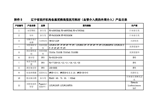
辽宁省医疗机构备案采购高值医用耗材(血管介入类的外周介入)产品目录
产品编号 产品名称
品牌
型号规格
生产商
1
血管鞘组 泰尔茂 RS*A50N25AQ.RS*A60N25AQ.RS*A70N25AQ
日本泰尔茂
2
导丝
泰尔茂 RF*PA35263M.RF*PS35263M
日本泰尔茂
动脉压迫止
3
血器
天津怡美 YM-GU-122P
GmbH& Co.Medizintechni
k KG
26
导丝
泰尔茂 RF*PA35153M RF*GA35183M RF*PA35183M; 直径:外径:0.035;长度:150/180cm
日本泰尔茂株式会 社
27
微导丝
ASAHI STM180-18S
朝日インテック株 式会社
28
微导管
ASAHI STD125-26S
Peripheral Vascular,Inc
37715120;37715220;37725120;
ReeKross 球
38050120;38050150;38050220;37950120;37950150;37950220;37725040;
爱尔兰
33
囊
巴德
38050040;38050080;37715040;37716040;37950040;37950080; 长度:
巴德
SK13514;SK15014;SK9018;SK13518;SK15018;SK6535M;SK9035M;SK13535M;SK15035M; 工作长度:150/135/90/65cm;兼容导丝:.014/.018/.035inch
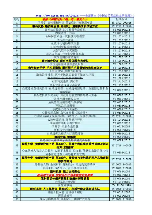
20160822全部医药强制性标准YY汇总0
49 50 51 52 53 54 55 56 57 58 59 60 61 62 63 64 65 66 67 68 69 70 71 72 73 74 75 76 77 78 79 80 81 82 83 84 85 86 87 88 89 90 91 92 93 94 95 96 97 98 99
神经和肌肉刺激器用电极
内镜器械 第2部分:腹腔镜用剪 牙科—光固化机 第2部分:发光二极管(LED)灯 血液透析和相关治疗用水处理设备技术要求 第2部分:用于单床透析 玻璃注射器 第2部分:蓝芯全玻璃注射器 等离子喷涂羟基磷灰石涂层 钛基牙种植体 立式蒸汽灭菌器 牙科学 汞及银合金粉 眼科光学 人工晶状体 第9部分:多焦人工晶状体 齿科藻酸盐印模材料
YY 0835-2011 YY 0837-2011 YY 0838-2011 YY 0843-2011 YY 0846-2011 YY 0847-2011 YY 0793.1-2010 YY 0801.2-2010 YY 0570-2013 YY 0573.3-2005 YY 0115-1993 YY 0500-2004 YY 0502-2005 YY 0337.1-2002 YY 0337.2-2002 YY 0346-2002 YY 0900-2013 YY 0334-2002 YY 0042-2007 YY 0498.2-2004 YY 0499-2004 YY 0803.1-2010 YY 0881-2013 YY 0166-2002 YY 91057-1999 YY 91064-1999 YY 91071-1999 YY 91072-1999 YY 91073-1999 YY 91092-1999 YY 91123-1999 YY 91146-1999 YY 0321.3-2009 YY 0331-2006 YY 0333-2010 YY 0790-2010 YY 0791-2010 YY 0792.2-2010 YY 0033-2000 YY 0045-2013 YY 0054-2010 YY 0059.1-1991 YY 0060-1991 YY 0065-2007 YY 0096-2009 YY 0097-1992 YY 0043-2005 YY 0068.1-2008 YY 0068.4-2009 YY 0070-2008 YY 0076-1992 YY 0450.2-2003 YY 0450.3-2007 YY 0459-2003
Amersham Imager 600
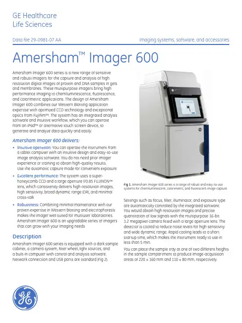
GE HealthcareLife SciencesData file 29-0981-07 AA Imaging systems, software, and accessories Amersham™ Imager 600Amersham Imager 600 series is a new range of sensitiveand robust imagers for the capture and analysis of highresolution digital images of protein and DNA samples in gelsand membranes. These multipurpose imagers bring highperformance imaging to chemiluminescence, fluorescence,and colorimetric applications. The design of AmershamImager 600 combines our Western Blotting applicationexpertise with optimized CCD technology and exceptionaloptics from Fujifilm™. The system has an integrated analysissoftware and intuitive workflow, which you can operatefrom an iPad™ or alternative touch screen device, togenerate and analyze data quickly and easily.Amersham Imager 600 delivers:• Intuitive operation: You can operate the instrument froma tablet computer with an intuitive design and easy-to-useimage analysis software. You do not need prior imagerexperience or training to obtain high-quality results.Use the automatic capture mode for convenient exposure• Excellent performance:The system uses a super-honeycomb CCD and a large aperture f/0.85 FUJINON™ lens, which consistently delivers high-resolution images, high sensitivity, broad dynamic range (DR), and minimal cross-talk• Robustness:Combining minimal maintenance with our proven expertise in Western blotting and electrophoresis makes the imager well suited for multiuser laboratories. Amersham Imager 600 is an upgradable series of imagers that can grow with your imaging needs DescriptionAmersham Imager 600 series is equipped with a dark sample cabinet, a camera system, filter wheel, light sources, anda built-in computer with control and analysis software. Network connection and USB ports are standard (Fig 2). Fig 1. Amersham Imager 600 series is a range of robust and easy-to-use systems for chemiluminescent, colorimetric, and fluorescent image capture. Settings such as focus, filter, illuminator, and exposure type are automatically controlled by the integrated software. You would obtain high resolution images and precise quantitation of low signals with the multipurpose 16-bit3.2 megapixel camera fitted with a large aperture lens. The detector is cooled to reduce noise levels for high sensitivity and wide dynamic range. Rapid cooling leads to a short startup time, which makes the instrument ready to use in less than 5 min.You can place the sample tray at one of two different heights in the sample compartment to produce image-acquisitionareas of 220 × 160 mm and 110 × 80 mm, respectively.2 29-0981-07 AAThe system can be used for a wide range of applications and it is fully upgradable between four different configurations (Table 1). Each configuration can be used for chemiluminescent detection and nonquantitative gel documentation. The different configurations are equipped with light sources and filters for UV and white light trans-illumination, and red, green and blueTable 1. Amersham Imager 600 series comprises four different configurations. Amersham Imager 600 QC is designed for QC applicationsAmersham Imager 600Amersham Imager 600UVAmersham Imager 600RGB Amersham Imager 600QCWhite light (epi)××××Chemiluminescence ××××UV Fluorescence o ×××RGB Fluorescence o o ×o White light (trans) calibrated OD measurements oo××× StandardO OptionalFig 2. Amersham Imager 600 is ready to capture images within 5 min after startup. The imager is equipped with USB ports and a network connection.Network connectionUSB portsUSB ports TouchscreenPower switch Sample tray Cabinet doorepi-illumination for multiple fluorescence detection. Optical density (OD) measurements are calibrated for quantitation of colorimetric staining applications.You can operate the system via an integrated computer, controlled from a wireless iPad, a USB-connected touch screen, or a traditional monitor with a mouse and keyboard.Imaging performanceA bright, wide aperture FUJINON f/0.85 lens developed for chemiluminescent imaging projects sharp images onto a specially patterned CCD (Fig 3).Fig 3. The special octagonal interwoven pixel layout offers a dense matrix fora more efficient capture of light compared to a standard, square-pixel layout.Intuitive operation and analysisAmersham Imager 600 can be controlled from either an iPad or an alternative touch screen device. The user interface is intuitive and the workflow is easy to follow. The system is fully automated, which means that after startup, you do not need to perform focusing, insertion of light sources, changing of filters, calibrations, or other adjustments.When the system is in automatic image capture mode, it performs a short pre-exposure of the whole sample to determine the optimum exposure time for the strongest signal without saturating the image so that an accurate quantitation of the sample can be attained. In semi-automatic image capture mode, an automated exposureis made based on an area of interest defined by you. Exposure times are also easy to set manually.After image acquisition, the seamless workflow allows youto detect and quantitate bands, determine molecular weight, and perform normalization. The results are presented in both tabular and graphical formats so that you can easily and quickly analyze your data. For additional flexibility during data analysis, we offer ImageQuant™ TL software.You can use the system to obtain images of colorimetric markers and stains, such as Coomassie™ Blue or silver. Moreover, white light imaging can be combined with chemiluminescence and fluorescence imaging to generate overlay images of marker and sample. This feature allows quick molecular weight estimation and simplified documentation.The images can be stored in the system, on a USB memory stick or external hard drive, or in a network folder. Examples of imaging applicationsThe following examples of applications illustrate the performance and flexibility of Amersham Imager 600. Chemiluminescent Western blotting detection Quantitative Western blotting requires a signal response that is proportional to the amount of protein. A broad dynamic range with linear response allows you to simultaneously quantitate both high and low levels of proteins. The combination of Amersham Imager 600 with either Amersham ECL™ Prime or Amersham ECL Select™ resultsin a limit of detection in the picogram range and a dynamic range covering three orders of magnitude.Amersham Imager 600 has high sensitivity, which allowsyou to detect very weak signals in chemiluminescence andfluorescence applications for both protein and nucleic acids.Moreover, the wide dynamic range of the imagers—over fourorders of magnitude—allows weak and strong signals tobe quantitated accurately at the same time. The camera iscooled to -25°C to reduce dark noise giving less backgroundnoise during longer exposure times, which is especiallyimportant for the precise quantitation of very weak signalsin chemiluminescent Western blotting. The images areautomatically corrected for both geometric and intensitydistortion (radial, dark frame, and flat frame) in each imagingmode. This provides images that need minimal post-processingfor publication.RobustnessAmersham Imager 600 is a highly robust series of instruments,making it suitable for multi-user environments. The imagersdo not require calibration. Short exposure times and a fastanalysis workflow means that several researchers can use thesystem in the course of a day. The camera system is designedfor simple operation.29-0981-07 AA 34 29-0981-07 AAFig 6. The chemiluminescence mode allows simultaneous imaging of chemiluminescent samples and colored molecular weight markers. This image was taken from experiments for optimizing the expression of the protein DHFR in E. coli grown under different conditions.Fig 7. Evaluation of linearity, dynamic range, and limit of detection forfluorescence detection with Amersham Imager 600. A two-fold dilution series of phosphorylase b prelabeled with Cy5 shows a dynamic range of 3.3 orders of magnitude.Fluorescent imagingAmersham Imager 600 combined with Amersham ECL Plex™ provides high-quality data in applications that demand high sensitivity over a wide dynamic range. Furthermore, theminimal crosstalk of Amersham Imager 600, and the spectrally resolved dyes Cy™2, Cy3, and Cy5, makes it a suitable system for a wide range of multiplexing applications, such as the detection of several proteins at the same time or different proteins of similar size.Sample:E. coli lysateMembrane: Amersham Hybond ECL Blocking: 3% BSA in PBS-TMarker:Full range ECL Plex Fluorescent Rainbow Marker Primary antibody: Rabbit anti DHFR C-terminal 1:1000Secondary antibody: ECL Anti-rabbit IgG horseradish peroxidase 1:100 000Detection: Amersham ECL Select Imaging:Amersham Imager 600Imaging method: Chemiluminescence with colorimetric markerSample: Two-fold dilution series of LMW marker with Phophorylase bstarting at 200 ng Prelabeling: Cy5Imaging:Amersham Imager 600Imaging method: Fluorescence Cy5Limit of detection: 98 pg phosphorylase b Dynamic range:3.3 orders of magnitude123456789DHFR8.07.06.05.04.03.0Log protein amount (pg)L o g i n t e g r a t e d i n t e n s i t yPhophorylase b200 ng98 pgFig 5. Evaluation of limit of detection with Amersham Imager 600 forchemiluminescence using a two-fold dilution series of transferrin from 625 pg.8.07.06.05.04.03.0Log protein amount (pg)L o g i nt e g r a t e d in t en s i t yTransferrin625 pg2.5 pgSample : Two-fold dilution series of transferrin from 625 pg to 2.5 pg Membrane : Amersham Hybond P Blocking :3% BSA in PBS-TPrimary antibody : Rabbit anti-transferrin 1:1000Secondary antibody : ECL Anti-rabbit IgG horseradish peroxidase 1:75 000 Detection : Amersham ECL Select Imaging :Amersham Imager 600Imaging method :Chemiluminescence Limit of detection (LOD): 2.5 pg transferrinFig 4. A two-fold dilution series of NIH/3T3 cell lysate starting at 5 µg total protein was subjected to chemiluminescent Western blotting and ERK was detected with Amersham ECL Select. Dynamic range and linearity weredetermined. ERK could be detected in a cell lysate with 9.8 ng of total protein. Amersham Imager 600 showed a linear response for chemiluminescent detection with low noise, high sensitivity, and a wide dynamic range.8.07.57.06.56.05.55.04.54.0Log cell lysate amount (ng)L o g i n te g r a t e d i n t en si t yNIH/3T3 cell lysate5 µg9.8 ngSample: NIH/3T3 cell lysate two-fold dilution series starting at 5 µg Membrane : Amersham Hybond™ P Blocking : Amersham ECL Prime blocking agent 2% in PBS-T Primary antibody : Rabbit anti-ERK1/2 1:10 000Secondary antibody : ECL Anti-rabbit IgG horseradish peroxidase 1:100 000Detection : Amersham ECL Select Imaging : Amersham Imager 600Imaging method : Chemiluminescence Dynamic range: 2.7 orders of magnitude Amersham Imager 600 offers chemiluminescence imaging with an automatic overlay function. This allows simultaneous imaging of a chemiluminescent sample and a colored molecular weight marker. The overlay image retains the marker color.29-0981-07 AA 5Fig 8. Multiplex detection of total protein and target protein with Amersham ECL Plex and Amersham Imager 600. Detection of DHFR (Cy3 green) in nine different samples from a growth optimization of E. coli. Total protein in the samples was prelabeled with Cy5 (red). The overlay image shows the DHFR band in yellow. Crosstalk between Cy5 and Cy3 was minimal for Amersham Imager 600, which makes it suitable for multiplex applications.Fig 9. (A) Proteins stained with Coomassie Brilliant Blue and detected with Amersham Imager 600. The illustration shows nine different samples of E. coli lysates, from a growth optimization experiment for the expression of DHFR. Purified DHFR was used as a reference (sample 10). (B) Two-fold dilution series of the LMW-SDS Marker stained with SYPRO Ruby and detected with Amersham Imager 600.Sensitive imaging of total protein stainsProteins may be visualized by treating a gel with a total protein stain after performing 1D or 2D electrophoresis. The most commonly used stains are Coomassie Blue or silver staining. Fluorescent staining methods such as SYPRO™ Ruby protein gel stain have the advantage of being more sensitive.Sample: E. coli lysates Blocking:3% BSA in PBS-TPrimary antibody: Rabbit anti DHFR C-terminal 1:1000Secondary antibody: ECL Plex Goat anti rabbit-Cy3 IgG 1:2500Imaging:Amersham Imager 600Imaging method: Fluorescence Cy3, Cy5Sample: E. coli lysatesMarker:Full range ECL Plex Fluorescent Rainbow Marker Post staining: Coomassie Brilliant Blue Imaging:Amersham Imager 600Imaging method:Colorimetiric, white light epi-illuminationSample: Two fold dilution seires of LMW markerstarting at 1000 ng Post staining: Sypro RubyImaging:Amersham Imager 600Imaging method: Fluorescence Blue Epi excitation Limit of detection: 2 ng of carbonic anhydrase123456789Prelabeling Cy5Total proteinWB: DHFR Cy3Overlay12345678910Carbonic anhydraseLMW 1000 ng2 ng(A)(B)6 29-0981-07 AAFig 11. Image of a two-fold dilution series of LMW-SDS Marker in a gel stained with Coomassie Brilliant Blue. The image was recorded on Amersham Imager 600 in trans-illumination mode, which allows you to measure the optical density of protein bands without calibration.Sample:Two fold dilution series of LMW marker Post staining: Coomassie Brilliant Blue Imaging:Amersham Imager 600Imaging method: Colorimetric white transillumination Limit of detection: 16 ng of carbonic anhydrase Dynamic range:1.8 orders of magnitudeLog amount of carbonic anhydrase (ng)L o g i n t e g r a t e d i n t e n s i t yLMW markers1000 ngDNA imagingElectrophoretic separation of DNA is a common technique that is typically used for the analysis of vector cleavages, DNA purification, and verification of successful PCR. Traditionally, ethidium bromide (EtBr) has been used for visualizing DNA, but today there are many alternative DNA stains available, such as SYBR™ Green.Fig 10.Three-fold dilution series of KiloBase DNA Marker in agarose gel stained with SYBR Green and detected with Amersham Imager 600.Sample:Three-fold dilution series of KiloBase DNA Marker Post staining: Sybr Green I nucleic acid gel stain Imaging:Amersham Imager 600Imaging method: Fluorescence Cy2Limit of detection: 0.3 ng of total DNA Dynamic range:2.9 orders of magnitude8.07.57.06.56.05.55.04.54.0Log amount of total DNA (pg)L o g i n t e g r a t e d i n t e n s i t yKiloBase DNA Marker 250 ngQuantitative OD measurementAmersham Imager 600 QC is a dedicated configuration for densitometry applications in a QC environment. The system contributes to a reliable control of products because it is equipped with highly sensitive optics that can detect trace amounts of impurities accurately. Amersham Imager 600 QC is available with IQ/OQ and validation support.Amersham Imager 600 is autocalibrated for accurate and reliable measurements of optical density of proteins stained with colorimetric stains such as Coomassie or silver.Installation and Operational Qualification (IQ/OQ) validation servicesGE Healthcare offers validation services to support your equipment throughout its entire life cycle. Our validation tests and protocols are developed and approved byvalidation experts and performed by trained and certified service engineers. Our approach is in alignment with GAMP5, ICH Q8-10 and ASTM E2500, whereby validation activities and documentation focus on what is critical for end-product quality, and are scaled according to risk, complexity, and novelty. Our validation offering includes Installation and Operational Qualification (IQ/OQ), Requalification, and Change Control Protocols (CCP).29-0981-07 AA 7Ordering informationProductCode number Amersham Imager 60029-0834-61Amersham Imager 600UV 29-0834-63Amersham Imager 600QC 29-0834-64Amersham Imager 600RGB29-0834-67Accessories included (depending on configuration)Black tray AI60029-0834-17UV trans tray AI60029-0834-19White trans Tray AI60029-0834-18White Insert AI60029-0880-60Diffuser Board AI60029-0834-20Additional Accessories Gel sheets (for UV trans tray)29-0834-57Apple iPad 2 Wi-Fi –16GB –Black 29-0938-27Touch Screen Monitor with Stand 29-0939-66RangeBooster N USB Adapter 29-0928-76Additional SoftwareImageQuant TL 8.1, node locked license*29-0007-37ImageQuant TL 8.1, 5 x 1 node locked license*29-0008-10* External computer needed. Cannot be installed on Amersham Imager 600.Upgrade options Part/DescriptionRelevant for configurationCode number AI600 Upgrade 600 to 600 UV 60029-0834-22AI600 Upgrade 600 UV to 600 QC 600 UV 29-0834-24 AI600 Upgrade 600 QC to 600 RGB 600 QC 29-0834-25 AI600 Upgrade 600 UV to 600 RGB 600 UV29-0834-26IQ/OQ Validation service Amersham Imager 600 IQ/OQ29-0983-45Technical featuresTable 2. Amersham Imager 600 RGB specificationsCCD model:Peltier cooled Fujifilm Super CCD Pixel area 15.6 × 23.4 mmLens model:FUJINON Lens f/0.85 43 mm Cooling:Two-stage thermoelectric module with air circulation CCD Operating temperature -25°C Cooling down time:< 5 minDynamic range:16-bit, 4.8 orders of magnitude CCD resolution:2048 × 1472, 3.2 MpixelImage resolution:Maximum 2816 × 2048, 5.8 Mpixel Operation:Fully automated (auto exposure, no focus or other adjustment or calibration needed)Capture modes:Automatic, semi-automatic, manual (normal/incremental)Exposure time:1/10 s to 1 hourPixel correction:Dark frame correction, flatframe correction, and distortion correctionImage output:Gray scale 16 bit tif, Color image jpg, Gray scale jpg Sample size:160 × 220 mm Light sources:Blue Epi light: 460 nm Green Epi light: 520 nm Red Epi light: 630 nmUV transillumination light: 312 nm White light: 470 to 635 nmEmission filters:Cy2: 525BP20Cy3/EtBr: 605BP40Cy5: 705BP40Interface:USB 2.0 and Ethernet port Dimensions (W × H × D): 360 × 785 × 485 mmWeight: 43.6 kg (Amersham Imager 600 RGB)Input voltage:100 to 240 V Voltage variation:±10%Frequency:50/60 Hz Max power:250 W Operating temperature:18°C to 28°CHumidity:20% to 70% (no dew condensation)imagination at work GE, imagination at work, and GE monogram are trademarks of General Electric Company.Amersham, Cy, Hybond, ImageQuant, ECL, and ECL Select are trademarks of GE Healthcare companies.Coomassie is a trademark of Imperial Chemical Industries, Ltd. Fujifilm and Fujinon are trademarks of Fujifilm Corporation. iPad is a trademark of Apple Inc. SYBR is a trademark of Life Technologies Corporation. SYPRO isa trademark of Life Technologies Corp.CyDye: This product is manufactured under an exclusive license from Carnegie Mellon University and is covered by US patent numbers 5,569,587 and 5,627,027.The purchase of CyDye products includes a limited license to use the CyDye products for internal research and development but not for any commercial purposes. A license to use the CyDye products for commercial purposes is subject to a separate license agreement with GE Healthcare. Commercial use shall include:1. Sale, lease, license or other transfer of the material or any material derived or produced from it.2. Sale, lease, license or other grant of rights to use this material or any material derived or produced from it.3. Use of this material to perform services for a fee for third parties, including contract research and drug screening. If you require a commercial license to use this material and do not have one, return this material unopened toGE Healthcare Bio-Sciences AB, Bjorkgatan 30, SE-751 84 Uppsala, Sweden and any money paid for the material will be refunded.GE Healthcare UK LimitedAmersham PlaceLittle ChalfontBuckinghamshire, HP7 9NAUKGE Healthcare Europe, GmbHMunzinger Strasse 5D-79111 FreiburgGermanyGE Healthcare Bio-Sciences Corp.800 Centennial Avenue, P.O. Box 1327Piscataway, NJ 08855-1327USAGE Healthcare Japan CorporationSanken Bldg., 3-25-1, HyakuninchoShinjuku-ku, Tokyo 169-0073Japan29-0981-07 AA 02/2014For local office contact information, visit /contact /imagingGE Healthcare UK LimitedAmersham PlaceLittle ChalfontBuckinghamshire HP7 9NAUnited Kingdom。
tslx
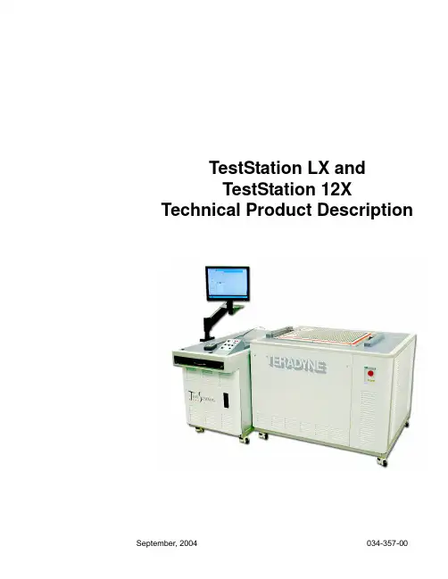
TestStation LX andTestStation 12X Technical Product DescriptiontTestStation LX andTestStation 12XTechnical Product DescriptionCopyright © Teradyne, Inc. 2004. All rights reserved under copyright laws of the United States and other countries. The technical data included herein, excluding computer software documentation, is subject to the LIMITED RIGHTS as set forth in FAR 52.227-15 (JUN 1987) and DFARS 252.227-7015 (JUN 1995). All technical data and computer software documentation contained herein is propri-etary and confidential to Teradyne, Inc. or its licensor. All computer software documentation contained herein is Commercial Com-puter Software Documentation, proprietary to Teradyne, Inc. or its licensor and furnished under limited license only. For solicitations issued by the United States, its agencies or instrumentalities (the "Government") on or after December 1, 1995 and the Department of Defense ("DoD") on or after September 29, 1995, the only rights provided in the Commercial Computer Software Documentation shall be those specified in a license customarily provided to the public by Teradyne, Inc. in accordance with FAR 12.212(a) and (b) (OCT 1995) or DFARS 227.7202-3(a) (JUN 1995). For solicitations issued before December 1, 1995 by the Government (other than DoD) use, duplication or disclosure of the documentation shall be subject to the RESTRICTED RIGHTS as set forth in subparagraph (c)(1) and (2) of the commercial computer software - restricted rights clause at FAR 52.227-19 (JUN 1987). For solicitations issued before September 29, 1995 by DoD: RESTRICTED RIGHTS LEGEND - The use, duplication, or disclosure by the Government is subject to restrictions as set forth in subparagraph (c)(1)(ii) of the Rights in Technical Data and Computer Software clause at DFARS 252.227-7013 (OCT 1988).The following are trademarks or registered trademarks of Teradyne, Inc.Product names listed are trademarks of their respective manufacturers. Company names listed are trademarks or trade names of their respective companies.The material in this manual is for informational purposes only and is subject to change, without notice. Teradyne assumes no respon-sibility for any error or for consequential damages that may result from the use or misinterpretation of any of the procedures in this publication.Access Analyzer™Ai-7 Series™Alchemist™APC™Argo™ATG XPRESS™AutoChecker™Autogen™AutoLoad™Autopub™Autotune™BasicSCAN™Bi4-Series™Bi-420™Boundary In-Circuit Test (BICT)™Boundary Scan Intelligent Diagnostics (BSID)™BusBust™BusScan™Call Sentinel™Cap Xpress™CapScan™CASTOR™CatSystem™CCU™Configural Recognition™CMU™Cshell™Component Designer (CDES)™D2B™Design-to-Build™D2B Alchemist™D2B DesignView™D2B ECO™D2B Strategist™D2B DFx™D-TRACKER™DBIU™Defect Display Station (DDS)™DeltaScan™Diamon™DigiBridge™DRMU™EJB-Tester™EJB-Monitor™EJB-Load™EJB-TestSuite™EKB-Test™E-MANAGER™E-SENTINEL™ENCOMPASS™FAST™FrameScan™FrameScan Plus™GENEVA®GenRad®GenRad CAT System™GR®GR-X90™GR-X130™GR-X130L™GR-X160L™GR-X1002™GR-X1500™GR-X1510™GR-X1525™GR-X1550™GR-X4005™GR-X4010™GR-X4011™GR-X7005™GR-X7010™GR2000™ GR4000™GR5000™GR 228X™GR & Des. ™GR AccelerATE®GR Advise™GR Navigate™GRNet™GR Producibility Analyzer™GR Stinger™GR SwitchManager™GR TestManager™GR TestStation™GR TestStation 12X™GR TestStation TSM™GR Versa™GR Versa OT™GR Xpert™GR X-Station 2D™GR X-Station 3-D™GridScan™Inline Device Programmer (ILDP) ™InterScan™Isolution™JUDGE™Junction Xpress™LASAR™L-Series™L200-Series™L300-Series™Lightning™M9-Series™MicroModal™Momentum™MultiScan™MultiScan II™Multi-Tester plus™NIM™NXR™Opens Xpress™Orient Xpress™Panel-Test™PinPoint™PRISM™Production Solutions International™Process Quality Manager™ProcessWatch™ProgramGuide™Program Xplorer™PrompTest™PXIscan™Quick-Check™QuickScan™RCU™RMU™SAC™Safecracker™SafeTest™Scan Pathfinder™Scavenger™Scot™ScratchProbe™SierraMate™SIMUL™Softbridge™Softbridge & Des.™ SoftProbe™Spectrum™Spectrum 8800-Series™SpeedPlus™Stinger™Stronghold™Syncload™The Technology of Knowledge®Teracode™Teradyne®TeraNet™Teradyne & Des. ™TestAdvisor™TestStudio™Test Toolbox™TEST XPRESS™TestLink™Testnet™TPS Converter Studio™TRACS™Vector Bus™Vector Performance (VP)™VICTORY™Virtual In-Circuit Test (VICT)™Virtual Component and Cluster Test (VCCT)™VRS™VXIscan®WaveScan™XFrame™XLT™Xpress Model™Xpress Start™Xpress Train™Xpress Transfer™Xpress Yield™XStation™XStation Combo™XStation HS™Z1800VP™Z1800-Series™Z1820VP™Z1840VP™Z1850VP™Z1880VP™Z1890VP™WARNINGS•Do not remove covers. Potentially lethal voltages are present inside the system. Observe all WARNING markings on the equipment and WARNING notices in the manual. If servicing is necessary, it should be performed only by a qualified person familiar with the electrical shock hazards present inside the system.•Grounding circuit continuity is vital for safe operation of the equipment. Never operate equipment with grounding conductor disconnected.•Safeguard your hands and fingers while handling any fixture or other accessory. Be sure it is securely supported if you reach under it. If it is heavy, you must have another person help to move it.•The symbol on equipment signifies that the manual contains information to prevent injury or equipment damage. Observe and heed all WARNING notices in the manuals and the equipment. WARNINGS call attention to personnel safety information.•Replace any fuse only with the same type and ratings as labeled on the equipment and/or listed in the manual.MISES EN GARDE•Ne pas enlever les couvercles. Les niveaux de tension se trouvant dans le système sont extrêmement dangereux. Respectez toutes les consignes de sécurité figurant sur l'équipement et les MISES EN GARDE données dan ce manuel. Seule une personne qualifée, connaisant les risques de décharge électrique du système, est autorisée à effecteur les opérations de nettoyage ou de réparation du système.•Le circuit doit être mis à la terre sans discontinuation pour garantir un fonctionnement sans danger de l'équipement. Ne jamais faire fonctionner l'équipement pendant que le raccord à la terre est déconnecté.•Protégez-vous les mains et les doigts pendant le maniement de tout dispositif de serrage ou autre accessoire.Assurez-vous que ceux-ci soient bien solidement fixés en place, avant de vous pencher sous eux. Si l'accessoire en question est trop lourd, faites-vous aider pour le déplacer.•Le symbole figurant sur l'équipement signifie que le manuel contient des informations permettant d'empêcher les accidents ou l'endommagement de l'équipement. Respectez toutes les consignes de MISES EN GARDE données dans le manuel et figurant sur l'équipement. Les MISES EN GARDE attirent l'attention sur la nécessité de se protéger.•Ne remplacez les fusibles qu'avec des fusibles du même type et de la même valuer que ceux mentionnés sur l'équipement et figurant dans le manuel.WARNHINWEISE•Abdeckungen nicht entfernen. Potentiell lebensgefährliche Spannungsbedingungen innerhalb des Systems vorhanden. Alle auf der Einrichtung befindlichen WARNMARKIERUNGEN und im Handbuch enthaltenen WARNHINWEISE beachten. Wartungsarbeiten dem qualifizierten Personal überlassen, das mit den innerhalb des Systems vorhandenen Gefahren eines elektrischen Schlags vertraut ist.•Die Erdung des Schaltungsdurchgangs ist eine Grundvoraussetzung für den sicheren Betrieb der Einrichtung.Einrichtung niemals ohne Erdleiter betreiben.•Hände und Finger bei der Handhabung einer Spannvorrichtung oder eines anderen Zubehörteils schützen.Sich vor der Plazierung der Hände unterhalb der Einrichtung vergewissern, daß die Einrichtung über ausreichenden Halt verfügt. Falls die Einrichtung schwer ist, sich von einer anderen Person beim Tragen helfen lassen.•Das auf der Einrichtung befindliche Symbol bedeutet, daß das Handbuch Informationen zur Verhinderung von Körperverletzungen oder Sachschäden enthält. Alle in den Handbüchern enthaltenen und auf der Einrichtung befindlichen WARNHINWEISE beachten und befolgen. WARNHINWEISE sollen auf Informationen zur persönlichen Sicherheit aufmerksam machen.•Sicherungen nur durch Sicherungen des gleichen Typs und der gleichen Nennleistung ersetzen. Auf der Einrichtung befindliche Etiketten und im Handbuch enthaltene Informationen zu Rate ziehen.!IEC417!IEC417!IEC417AVISOS•Não remova as tampas. Há voltagens potencialmente fatais presentes na parte interna do sistema. Observe todas as marcações de AVISOS no equipamento e discrições de AVISOS no manual. Se for necessário fazer manutenção, esta deve ser feita somente por uma pessoa qualificada familiarizada com os perigos de choques elétricos presentes na parte interna do sistema.• A continuidade do circuito de aterramento é vital para a operação segura do equipamento. Nunca opere o equipamento com o cabo de aterramento desligado.•Proteja as suas mãos e dedos ao operar qualquer dispositivo ou outro acessório. Certifique-se que ele esteja suportado com segurança se você tiver que alcançar algo debaixo dele. Se for pesado, você deve ter a ajuda de uma outra pessoa para movê-lo.•O simbolo no equipamento significa que o manual contém informações para prevenir ferimentos ou danos ao equipamento. Observe e preste atenção a todos os AVISOS nos manuais e no equipamento.Os AVISOS chamam a atenção a informações sobre a segurança pessoal.•Substitua qualquer fusivel somente com um do mesmo tipo e da mesma capacidade nominal como marcado no equipamento e listado no manual.ADVERTENCIAS•No quitar las tapas. En el interno del sistema hay voltajes potencialmente mortales. Obsérvense todos los rótulos de ADVERTENCIA presentes en el equipo, así como la descripción de las notas de ADVERTENCIA presentadas en el manual. De ser necesario, el servicio de mantenimiento deberá ser efectuado únicamente por personal calificado que esté familiarizado con los peligros de choque eléctrico presentes en el sistema.•La continuidad del circuito de puesta a tierra es de vital importancia para el functionamiento seguro del equipo.Nunca se debe usar el equipo con el conductor de puesta a tierra desconectado.•Protéjanse las manos y los dedos toda vez que sea necesario manipular un dispositivo u accesorio.Cerciorarse de que el mismo esté firmemente sujetado antes de proceder a trabajar debajo de él. Si el aparato u accesorio fuera pesado, pedir la ayuda de otra persona para moverlo.•El simbolo que aparece en el equipo significa que el manual contiene informaciones para evitar lesiones personales o daños al equipo. Obsérvense y préstese atención a toda las notas de ADVERTENCIA presentes en los manuales y en el equipo. Las ADVERTENCIAS sirven para llamar la atención sobre informaciones de seguridad para el personal.•Reemplazar los fusibles únicamente con otros del mismo tipo y capacidad, según lo indique el rótulo en el equipo y la descripción en el manual.CAUTIONS•Observe and heed all CAUTION notices in the manuals and on the equipment. CAUTIONS call attention to information about safeguarding equipment from damage.!IEC417!IEC417HANDLING PRECAUTIONS FOR ELECTRONIC DEVICES SUBJECT TO DAMAGE BY STATIC ELECTRICITYPlace instrument or module to be serviced, spare parts in conductive (anti-static) envelopes or carriers, hand tools etc. on a work surface defined as follows. The work surface must be conductive and reliably connected to earth ground through a safety resistance of approximately 250 kilohms. The sur-face must NOT be metal. (A resistivity of 30 to 300 kilohms per square inch is suggested.) Avoid placing tools or electri-cal parts on insulators.Ground the frame of any line-powered equipment, test instru-ments, lamps, soldering irons, etc., directly to earth ground. To avoid shorting out the safety resistance, be sure that grounded equipment has rubber feet or other means of insu-lation from the work surface. The module being serviced should be insulated while grounded through the power-cord ground wire, but must be connected to the work surface before, during and after any disassembly or other procedure in which the line cord is disconnected.Exclude any hand tools (such as non-conductive plunger-type solder suckers) that can generate a static charge.Ground yourself reliably, through a resistance, to the work surface; use, for example, a conductive strap or cable with a wrist cuff. The cuff must make electrical contact directly with your skin; do NOT wear it over clothing. (Resistance between skin contact and work surface through a commer-cially available personnel grounding device is typically 250 kilohms to 1 megohm.)If any circuit or IC packages are to be stored or transported, enclose them in conductive envelopes or carriers. Remove them only with the above precautions; handle IC packages without touching the contact pins.Avoid circumstances that are likely to produce static charges, such as wearing clothes of synthetic material, sitting on a plastic-covered stool (particularly while wearing wool), comb-ing your hair, or making extensive erasures. These circum-stances are most significant when the air is dry.When testing static sensitive devices, be sure DC power is on before, during, and after application of test signals. Be sure all pertinent voltages have been switched off while boards orcomponents are removed or inserted.ContentsUsing This ManualOverview . . . . . . . . . . . . . . . . . . . . . . . . . . . . . . . . . . . . . . . . . . . . . . . . . . . . . . . . . . . . . . . . . . . . . . xi Technical Support Center . . . . . . . . . . . . . . . . . . . . . . . . . . . . . . . . . . . . . . . . . . . . . . . . . . . . . . . . . xi How To Order Additional Documentation. . . . . . . . . . . . . . . . . . . . . . . . . . . . . . . . . . . . . . . . . . . . . . xii Patent Information . . . . . . . . . . . . . . . . . . . . . . . . . . . . . . . . . . . . . . . . . . . . . . . . . . . . . . . . . . . . . . . xiiIntroductionIntroduction . . . . . . . . . . . . . . . . . . . . . . . . . . . . . . . . . . . . . . . . . . . . . . . . . . . . . . . . . . . . . . . . . . .1 - 1 Standard System Configuration. . . . . . . . . . . . . . . . . . . . . . . . . . . . . . . . . . . . . . . . . . . . . . . . . . . .1 - 3 System Software . . . . . . . . . . . . . . . . . . . . . . . . . . . . . . . . . . . . . . . . . . . . . . . . . . . . . . . . . . .1 - 3 Test Hardware . . . . . . . . . . . . . . . . . . . . . . . . . . . . . . . . . . . . . . . . . . . . . . . . . . . . . . . . . . . . .1 - 4 Computer and Peripherals . . . . . . . . . . . . . . . . . . . . . . . . . . . . . . . . . . . . . . . . . . . . . . . . . . . .1 - 6 Service and Support . . . . . . . . . . . . . . . . . . . . . . . . . . . . . . . . . . . . . . . . . . . . . . . . . . . . . . . . .1 - 6 Optional System Software . . . . . . . . . . . . . . . . . . . . . . . . . . . . . . . . . . . . . . . . . . . . . . . . . . . . . . . .1 - 6 Optional System Hardware . . . . . . . . . . . . . . . . . . . . . . . . . . . . . . . . . . . . . . . . . . . . . . . . . . . . . . .1 - 7 Optional Computer Peripherals . . . . . . . . . . . . . . . . . . . . . . . . . . . . . . . . . . . . . . . . . . . . . . . . . . . .1 - 8 Overview of Software Licenses . . . . . . . . . . . . . . . . . . . . . . . . . . . . . . . . . . . . . . . . . . . . . . . . . . . .1 - 8Analog SubsystemOverview . . . . . . . . . . . . . . . . . . . . . . . . . . . . . . . . . . . . . . . . . . . . . . . . . . . . . . . . . . . . . . . . . . . . .2 - 1 Instrumentation . . . . . . . . . . . . . . . . . . . . . . . . . . . . . . . . . . . . . . . . . . . . . . . . . . . . . . . . . . . . . . . .2 - 2 ICA Module . . . . . . . . . . . . . . . . . . . . . . . . . . . . . . . . . . . . . . . . . . . . . . . . . . . . . . . . . . . . . . . .2 - 2 Digital Voltmeter (DVM) . . . . . . . . . . . . . . . . . . . . . . . . . . . . . . . . . . . . . . . . . . . . . . . . . . . . . .2 - 3 AC and DC Current Measure . . . . . . . . . . . . . . . . . . . . . . . . . . . . . . . . . . . . . . . . . . . . . . . . . .2 - 3 DC/AC Source Amplifiers . . . . . . . . . . . . . . . . . . . . . . . . . . . . . . . . . . . . . . . . . . . . . . . . . . . . .2 - 3 Impedance Measurement . . . . . . . . . . . . . . . . . . . . . . . . . . . . . . . . . . . . . . . . . . . . . . . . . . . . .2 - 4 Arbitrary Waveform Generator (AWG) . . . . . . . . . . . . . . . . . . . . . . . . . . . . . . . . . . . . . . . . . . .2 - 4 Digital Multimeter (DMM) . . . . . . . . . . . . . . . . . . . . . . . . . . . . . . . . . . . . . . . . . . . . . . . . . . . . .2 - 5 ICA Controls, Triggers, and Timers . . . . . . . . . . . . . . . . . . . . . . . . . . . . . . . . . . . . . . . . . . . . .2 - 5 ICA Instrument Multiplexer . . . . . . . . . . . . . . . . . . . . . . . . . . . . . . . . . . . . . . . . . . . . . . . . . . . .2 - 6 High Voltage Source . . . . . . . . . . . . . . . . . . . . . . . . . . . . . . . . . . . . . . . . . . . . . . . . . . . . . . . . .2 - 6 Calibration Daughter Board . . . . . . . . . . . . . . . . . . . . . . . . . . . . . . . . . . . . . . . . . . . . . . . . . . .2 - 6 Self-Test Circuits . . . . . . . . . . . . . . . . . . . . . . . . . . . . . . . . . . . . . . . . . . . . . . . . . . . . . . . . . . .2 - 6 IEEE-488 Multiplexer . . . . . . . . . . . . . . . . . . . . . . . . . . . . . . . . . . . . . . . . . . . . . . . . . . . . . . . .2 - 7ContentsRelay-Driver Function . . . . . . . . . . . . . . . . . . . . . . . . . . . . . . . . . . . . . . . . . . . . . . . . . . . . . . . .2 - 7 ICA Specifications . . . . . . . . . . . . . . . . . . . . . . . . . . . . . . . . . . . . . . . . . . . . . . . . . . . . . . . . . .2 - 8 High Voltage Source . . . . . . . . . . . . . . . . . . . . . . . . . . . . . . . . . . . . . . . . . . . . . . . . . . . . . . . .2 - 11 AWG Source . . . . . . . . . . . . . . . . . . . . . . . . . . . . . . . . . . . . . . . . . . . . . . . . . . . . . . . . . . . . . .2 - 14 Scanner Switching Matrix. . . . . . . . . . . . . . . . . . . . . . . . . . . . . . . . . . . . . . . . . . . . . . . . . . . . . . . .2 - 16 Switching Matrix Specifications . . . . . . . . . . . . . . . . . . . . . . . . . . . . . . . . . . . . . . . . . . . . . . .2 - 20 Measurement Methods and Specifications . . . . . . . . . . . . . . . . . . . . . . . . . . . . . . . . . . . . . . . . . .2 - 22 UUT Shorts Test . . . . . . . . . . . . . . . . . . . . . . . . . . . . . . . . . . . . . . . . . . . . . . . . . . . . . . . . . . .2 - 22 Opens Test . . . . . . . . . . . . . . . . . . . . . . . . . . . . . . . . . . . . . . . . . . . . . . . . . . . . . . . . . . . . . . .2 - 22 Capacitive Tests . . . . . . . . . . . . . . . . . . . . . . . . . . . . . . . . . . . . . . . . . . . . . . . . . . . . . . . . . . .2 - 23 Junction Xpress . . . . . . . . . . . . . . . . . . . . . . . . . . . . . . . . . . . . . . . . . . . . . . . . . . . . . . . . . . .2 - 25 Resistance Measurements . . . . . . . . . . . . . . . . . . . . . . . . . . . . . . . . . . . . . . . . . . . . . . . . . . .2 - 25 Impedance Measurements . . . . . . . . . . . . . . . . . . . . . . . . . . . . . . . . . . . . . . . . . . . . . . . . . . .2 - 32 AC Resistance . . . . . . . . . . . . . . . . . . . . . . . . . . . . . . . . . . . . . . . . . . . . . . . . . . . . . . . . . . . .2 - 32 Capacitance Test . . . . . . . . . . . . . . . . . . . . . . . . . . . . . . . . . . . . . . . . . . . . . . . . . . . . . . . . . .2 - 33 Inductance Test Procedures . . . . . . . . . . . . . . . . . . . . . . . . . . . . . . . . . . . . . . . . . . . . . . . . . .2 - 35 6-Wire AC Measurement . . . . . . . . . . . . . . . . . . . . . . . . . . . . . . . . . . . . . . . . . . . . . . . . . . . .2 - 36 Diode Test . . . . . . . . . . . . . . . . . . . . . . . . . . . . . . . . . . . . . . . . . . . . . . . . . . . . . . . . . . . . . . .2 - 37 Transistor Test. . . . . . . . . . . . . . . . . . . . . . . . . . . . . . . . . . . . . . . . . . . . . . . . . . . . . . . . . . . . . . . .2 - 38 NPN and PNP Tests . . . . . . . . . . . . . . . . . . . . . . . . . . . . . . . . . . . . . . . . . . . . . . . . . . . . . . . .2 - 38 FET Channel Impedance Test . . . . . . . . . . . . . . . . . . . . . . . . . . . . . . . . . . . . . . . . . . . . . . . .2 - 39 Zener Diode Test . . . . . . . . . . . . . . . . . . . . . . . . . . . . . . . . . . . . . . . . . . . . . . . . . . . . . . . . . .2 - 39 SCR Test . . . . . . . . . . . . . . . . . . . . . . . . . . . . . . . . . . . . . . . . . . . . . . . . . . . . . . . . . . . . . . . .2 - 40 Operational Amplifier Test . . . . . . . . . . . . . . . . . . . . . . . . . . . . . . . . . . . . . . . . . . . . . . . . . . .2 - 41 Analog Functional/Mixed Signal Testing . . . . . . . . . . . . . . . . . . . . . . . . . . . . . . . . . . . . . . . . . . . .2 - 42Digital SubsystemOverview . . . . . . . . . . . . . . . . . . . . . . . . . . . . . . . . . . . . . . . . . . . . . . . . . . . . . . . . . . . . . . . . . . . . .3 - 1 System Controller. . . . . . . . . . . . . . . . . . . . . . . . . . . . . . . . . . . . . . . . . . . . . . . . . . . . . . . . . . . . . . .3 - 2 Controller Functions . . . . . . . . . . . . . . . . . . . . . . . . . . . . . . . . . . . . . . . . . . . . . . . . . . . . . . . . .3 - 2 Clock/Sync/Trigger Logic. . . . . . . . . . . . . . . . . . . . . . . . . . . . . . . . . . . . . . . . . . . . . . . . . . . . . . . . .3 - 3 Timing Specifications for the CST . . . . . . . . . . . . . . . . . . . . . . . . . . . . . . . . . . . . . . . . . . . . . .3 - 4 Clock Drive/Synchronization for the CST . . . . . . . . . . . . . . . . . . . . . . . . . . . . . . . . . . . . . . . . .3 - 4 Trigger Pins for the CST . . . . . . . . . . . . . . . . . . . . . . . . . . . . . . . . . . . . . . . . . . . . . . . . . . . . . .3 - 5 Driver/Sensor Modules. . . . . . . . . . . . . . . . . . . . . . . . . . . . . . . . . . . . . . . . . . . . . . . . . . . . . . . . . . .3 - 6 Driver/Sensor Architecture . . . . . . . . . . . . . . . . . . . . . . . . . . . . . . . . . . . . . . . . . . . . . . . . . . . .3 - 7 Additional Features of Ultra 12X Pin Boards . . . . . . . . . . . . . . . . . . . . . . . . . . . . . . . . . . . . . .3 - 9 SafeTest. . . . . . . . . . . . . . . . . . . . . . . . . . . . . . . . . . . . . . . . . . . . . . . . . . . . . . . . . . . . . . . . . . . . .3 - 10ContentsAutomatic Driver Verification . . . . . . . . . . . . . . . . . . . . . . . . . . . . . . . . . . . . . . . . . . . . . . . . .3 - 10 Real-Time Backdrive Current Measurement Capabilities . . . . . . . . . . . . . . . . . . . . . . . . . . . .3 - 10 Closed Loop, Low Output Impedance Drivers . . . . . . . . . . . . . . . . . . . . . . . . . . . . . . . . . . . .3 - 10 Multi-Level Digital Isolation . . . . . . . . . . . . . . . . . . . . . . . . . . . . . . . . . . . . . . . . . . . . . . . . . . .3 - 10 Per Pin Programmable Logic Level Assignments . . . . . . . . . . . . . . . . . . . . . . . . . . . . . . . . .3 - 10 Programmable Backdrive Currents and Duration . . . . . . . . . . . . . . . . . . . . . . . . . . . . . . . . . .3 - 11 Specialized Digital Controller and Timing . . . . . . . . . . . . . . . . . . . . . . . . . . . . . . . . . . . . . . . .3 - 11Optional Test HardwareOverview . . . . . . . . . . . . . . . . . . . . . . . . . . . . . . . . . . . . . . . . . . . . . . . . . . . . . . . . . . . . . . . . . . . . .4 - 1 Analog Functional Test Module (AFTM) . . . . . . . . . . . . . . . . . . . . . . . . . . . . . . . . . . . . . . . . . . . . .4 - 1 AFTM Specifications . . . . . . . . . . . . . . . . . . . . . . . . . . . . . . . . . . . . . . . . . . . . . . . . . . . . . . . . .4 - 2 DC Voltage Measure . . . . . . . . . . . . . . . . . . . . . . . . . . . . . . . . . . . . . . . . . . . . . . . . . . . . . . . .4 - 2 AC Voltage Measure . . . . . . . . . . . . . . . . . . . . . . . . . . . . . . . . . . . . . . . . . . . . . . . . . . . . . . . .4 - 3 DC Source . . . . . . . . . . . . . . . . . . . . . . . . . . . . . . . . . . . . . . . . . . . . . . . . . . . . . . . . . . . . . . . .4 - 3 AC Source . . . . . . . . . . . . . . . . . . . . . . . . . . . . . . . . . . . . . . . . . . . . . . . . . . . . . . . . . . . . . . . .4 - 4 Sync Source . . . . . . . . . . . . . . . . . . . . . . . . . . . . . . . . . . . . . . . . . . . . . . . . . . . . . . . . . . . . . . .4 - 4 Instrument Multiplexer . . . . . . . . . . . . . . . . . . . . . . . . . . . . . . . . . . . . . . . . . . . . . . . . . . . . . . .4 - 4 Frequency/Time Interval Meter (FTM) . . . . . . . . . . . . . . . . . . . . . . . . . . . . . . . . . . . . . . . . . . .4 - 5 Deep Serial Memory . . . . . . . . . . . . . . . . . . . . . . . . . . . . . . . . . . . . . . . . . . . . . . . . . . . . . . . . . . . .4 - 5 DSM Applications . . . . . . . . . . . . . . . . . . . . . . . . . . . . . . . . . . . . . . . . . . . . . . . . . . . . . . . . . . .4 - 6 Custom Function Board (CFB). . . . . . . . . . . . . . . . . . . . . . . . . . . . . . . . . . . . . . . . . . . . . . . . . . . . .4 - 7 Custom Function Board Applications . . . . . . . . . . . . . . . . . . . . . . . . . . . . . . . . . . . . . . . . . . . .4 - 8 Vehicle Control Interface (VCI) . . . . . . . . . . . . . . . . . . . . . . . . . . . . . . . . . . . . . . . . . . . . . . . . .4 - 8 Frequency/Time Interval Instrument Module (FTI) . . . . . . . . . . . . . . . . . . . . . . . . . . . . . . . . . .4 - 8 FTI Specifications . . . . . . . . . . . . . . . . . . . . . . . . . . . . . . . . . . . . . . . . . . . . . . . . . . . . . . . . . .4 - 9 Duty Cycle . . . . . . . . . . . . . . . . . . . . . . . . . . . . . . . . . . . . . . . . . . . . . . . . . . . . . . . . . . . . . . .4 - 10 System Frequency/Time Meter (SFTM). . . . . . . . . . . . . . . . . . . . . . . . . . . . . . . . . . . . . . . . . . . . .4 - 10Unit Under Test Power SuppliesOverview . . . . . . . . . . . . . . . . . . . . . . . . . . . . . . . . . . . . . . . . . . . . . . . . . . . . . . . . . . . . . . . . . . . . .5 - 1 Programmable Voltage Power Supplies . . . . . . . . . . . . . . . . . . . . . . . . . . . . . . . . . . . . . . . . . . . . .5 - 1 Common Specifications . . . . . . . . . . . . . . . . . . . . . . . . . . . . . . . . . . . . . . . . . . . . . . . . . . . . . .5 - 2 Programmable Power Supply Specifications . . . . . . . . . . . . . . . . . . . . . . . . . . . . . . . . . . . . . .5 - 3 Optional Fixed Voltage Power Supplies. . . . . . . . . . . . . . . . . . . . . . . . . . . . . . . . . . . . . . . . . . . . . .5 - 4System Layout and Mechanical/Industrial SpecificationsSystem Layout. . . . . . . . . . . . . . . . . . . . . . . . . . . . . . . . . . . . . . . . . . . . . . . . . . . . . . . . . . . . . . . . .6 - 1 Power Bay . . . . . . . . . . . . . . . . . . . . . . . . . . . . . . . . . . . . . . . . . . . . . . . . . . . . . . . . . . . . . . . .6 - 1。
BV船级社型式认可试验标准
of control elements in the case of computer systems
July 2011 with January 2012 amendments
standard atmosphere conditions temperature: 25°C ± 10°C relative humidity: 60% ± 30% air pressure: 96 KPa ± 10 KPa
Other information
• drawings, design data
2-30 Test Db
Humidity: 95%
Duration: 2 cycles (12 + 12 hours)
• measurement of insulation resistance before test
ripple voltage from the charging
device
• +20% to –25% for equipment not
connected to the battery during
charging
4c Pneumatic and
−
Pressure: ± 20%
hydraulic
4a Electric A.C. power supply variations
−
COMBINATION
Voltage variation Frequency varia-
permanent
tion permanent
ADC121C021资料
Key Specifications
■ Resolution
12 bits; no missing codes
■ Conversion Time
1µs (typ)
■ INL & DNL
±1 LSB (max) (up to 22kSPS)
■ Throughput Rate
188.9kSPS (max)
Block Diagram
Package TSOT-6 TSOT-6 Tape-and-Reel TSOT-6 TSOT-6 Tape-and-Reel
Evaluation Board
Top Mark X30C X30C X31C X31C
30020903
2
ADC121C021/ADC121C027
Normal power consumption using a +3V or +5V supply is 0.26mW or 0.78mW, respectively. The automatic powerdown feature reduces the power consumption to less than 1µW while not converting. Operation over the industrial temperature range of −40°C to +105°C is guaranteed. Their low power consumption and small packages make this family of ADCs an excellent choice for use in battery operated equipment.
计量标准代码
计量标准名称代码目录计量标准代码计量标准名称01000000几何量01191420手持式激光测距仪检定装置01200000线纹01200011激光干涉仪工作基准装置01200012长光栅工作基准装置01200013长光栅位移传感器工作基准装置01200014长光栅测量系统工作基准装置01213300显微标尺标准器01213500基线场检定装置01213700基线尺检定装置01213705光学机械比较仪标准装置01213711双频激光干涉仪标准装置01213712纳米光栅校准装置01213730温度线膨胀系数检定装置01214100长光栅检定装置01214107长光栅线位移传感器标准装置01214109位移测量仪检定装置01214110引伸计检定装置01214500线纹尺检定装置01214501光电光波比长仪标准装置01214900线纹尺标准装置01214901激光干涉比长仪标准装置01214910一等线纹尺标准装置01214920二等线纹尺标准装置01214930三等线纹尺标准装置01214931一等金属线纹尺标准装置01214935二等金属线纹尺标准装置01214937三等金属线纹尺标准装置01214939三等金属线纹尺检定装置01214951一等玻璃线纹尺标准装置01214955二等玻璃线纹尺标准装置01214956短标尺标准装置01215500钢卷尺标准装置01215501π尺标准装置01215600纤维细度测微尺标准装置01215900木 (折) 直尺检定装置01215901水平尺校准装置01215902通用卡尺检定装置01216600玻璃线纹尺标准装置01217500基线场标准装置01253100因瓦水准标尺检定装置01300000端度01300011量块工作基准装置01313200量块检定装置01313231柯氏干涉仪标准装置01313233激光干涉仪标准装置01313251测长机标准装置01313300量块标准装置01313311一等量块标准装置01313322二等量块标准装置01313333三等量块标准装置01313334引伸计标定器检定装置01313344四等量块标准装置01313355薄量块标准装置01313700光面量规标准装置01313800滚动轴承径向游隙标准装置01313900环规检定装置01313901电容式条干均匀度仪标准器检定装置01314000圆锥量规标准装置01314001园度标准装置01314002圆度、圆柱度测量仪标准装置01314032一等圆锥量规标准装置01314100圆锥塞规检定装置01314300塞尺检定装置01314320塞规检定装置01314500三针检定装置01314510三针量规检定装置01314600千分表检定仪检定装置01314700千分表检定仪标准装置01314710千分表、百分表检定仪标准装置01314800百分表检定仪检定装置01314900百分表检定仪标准装置01315300检定游标量具标准器组01315310检定万能量具标准装置01315400检定测微量具标准器组01315500检定指示量具标准器组01316500端度测量仪器检定装置01316501接触式干涉仪检定装置01316502(分度值0.02m)光学计检定装置01316503光学计检定装置01316505测长仪检定装置01316506测长机检定装置01316507电感式比较仪检定装置01316508测厚仪检定装置01316509镀层膜厚标准装置01316515小角度测量仪检定装置01316517孔径测量仪检定装置01316518孔板几何尺寸检定装置01316600玻璃刻度尺标准装置01317300线宽检定装置01318300波长标准器01318301光波长标准装置01318307氦氖激光标准器01318309兰姆凹陷稳频激光标准器01318311双频激光标准器01500000角度01513100正多面棱体标准器组01513101一等正多面棱体标准器组01513102二等正多面棱体标准器组01513103三等正多面棱体标准器组01513104四等正多面棱体标准器组01513105光电度盘检定装置01513106光电度盘检查仪标准装置01513200多齿分度台标准装置01513500正多面棱体标准装置01513600正多面棱体检定装置01513602测角仪标准装置01513701光学角规检定装置01513900检定圆分度校准仪标准器01513905圆光栅标准器01513911度盘标准器01513917圆感应同步器标准器01514000圆分度校准仪标准装置01514100旋光度标准装置01514600光学分度台标准装置01515500小角度检查仪标准装置01515502合象水平仪检定装置01515503电子水平仪检定装置01515504光学测角比较仪检定装置01515900角度块检定装置01516000角度块标准装置015160010 级角度块标准器组015160111 级角度块标准器组015160222 级角度块标准器组01516200角度规检定装置01516500圆光栅检定装置01516600圆锥量规检定装置01516800方箱检定装置01517100直角尺检定装置01517200直角尺检定仪检定装置01517500正弦尺检定装置01517600样板直尺检定装置01517700平面等倾干涉仪标准装置01517701平面度标准装置01517900平面平晶检定装置01518200平面平晶标准装置01518201长平晶标准装置01518500研磨面平尺检定装置01518700平尺、平板检定装置01518800水平仪检定装置01518900水平仪检定器检定装置01600000粗糙度01613100单刻线样板标准装置01613101单刻线样板检定装置01613110粗糙度标准样板检定装置01613200多刻线样板标准装置01613210多刻线样板标准器组01613211单刻线样板标准器组01613300表面粗糙度比较样板标准装置01613301表面粗造度比较样板检定装置01613302表面粗糙度测量仪检定装置01613303表面粗糙度比较样块校准装置01613310检定粗糙度仪器标准器组01613311光切显微镜检定装置01613323干涉显微镜检定装置01613325电动轮廓仪检定装置01700000螺纹, 齿轮01700011齿轮渐开线工作基准装置01711350齿轮螺旋线样板检定装置01711360齿轮齿距检定装置01712200齿轮测量中心标准装置01713200齿轮齿距标准装置01713300螺旋线样板标准装置01713400渐开线样板检定装置01713401点数渐开线标准装置01713402齿轮浙开线样板检定装置01713500渐开线样板标准器组01713501检定齿轮仪器标准器组01713502检定螺旋线检查仪标准器组01713503齿轮渐开线样板标准器组01713506万能渐开线检查仪标准装置01713507检定万能渐开线检查仪标准器组01713519检定单盘渐开线检查仪标准器组01713600螺旋线样板标准器组01713610齿轮单齿仪标准装置01714500石油套管螺纹量规校准装置01714600螺纹, 丝杆检定装置01714700半径螺纹样板检定装置01714800石油钻杆接头螺纹量规校准装置01714900石油油管螺纹量规检定装置01800000形位01813200检定座标测量仪标准器组01813201激光两座标测量仪标准装置01813202校准坐标测量机标准器组01813300圆度仪检定装置01813311圆度标准装置01813500圆柱度检定装置01900000其他01912000光学仪器检具检定装置01913100检定皮革面积测量机标准器组01913400检定光学仪器标准器组01913500万能测量显微镜标准装置01914100皮革面积计检定装置01914500光电测距仪检定装置01914600光电测距仪全站仪检定装置01914700全球卫星定位系统(GPS)接收机校准装置01914800水准仪检定装置01914810经纬仪、水准仪检定装置01914900经纬仪检定装置01914910空间角度标准装置01914920水平准线标准装置01915100光纤参数标准装置01921100纳米几何结构检定装置04000000热学04100000温度04100011铂电阻温度计工作基准装置041000121.2~24K温度工作基准装置04100013温度灯工作基准装置04100014低温铂电阻温度计工作基准装置04100015中温铂电阻温度计工作基准装置04100016套管铂电阻温度计标准装置04100017长杆铂电阻温度计标准装置0410001883.8058~1234.93K温度工作基准装置04113100高温铂电阻温度计标准装置04113200热电偶标准装置04113201铂铑10-铂热电偶标准装置04113205标准组铂铑10-铂热电偶固定点检定装置04113210标准铂铑10-铂热电偶组标准装置04113211一等铂铑10-铂热电偶标准装置04113212二等铂铑10-铂热电偶标准装置04113221一等铂铑30-铂铑6热电偶标准装置04113223二等铂铑30-铂铑6热电偶标准装置04113233一级铂铑13-铂热电偶标准装置04113234二级铂铑13-铂热电偶标准装置04113246铜-康铜热电偶标准装置04113249镍铬-镍硅热电偶标准装置04113300动态温度标准装置04113710钨铼热电偶检定装置04113800热电阻温度计标准装置04113801一等铂电阻温度计标准装置04113803二等铂电阻温度计标准装置04114700温度计标准装置04114701一等水银温度计标准装置04114702二等水银温度计标准装置04114703二等体温计标准装置04114704贝克曼温度计标准装置04115000数字温度计检定装置04115100石英频率温度计标准装置04115110石英晶体数字温度计标准装置04115200低温铂电阻温度计标准装置04115300低温度计检定装置04115321(15-200mK)铑铁、铂电阻标准装置04115355(0.5-9.2K)温度标准装置04115367(0.5-30 K)温度标准装置04115400低温金属导热系数标准装置04117100温度二次仪表检定装置04117101配热电阻用温度仪表检定装置04117103配热电隅用温度仪表检定装置04117105电子自动平衡电桥检定装置04117106自动平衡式显示仪表检定装置04117107电子自动电位差计检定装置04117108温度变送器检定装置04117109温度变送器标准装置04117600温度灯标准器04117700温度灯标准装置04117701银和铝凝固温度灯标准装置04118100光学高温计标准装置04118101辐射高温计检定装置04118200光学高温计标准装置04118300非接触式测温仪检定装置04118301光学高温计检定装置04118303隐丝式光学高温计检定装置04118305辐射感温器检定装置04118310热流量标准装置04118320辐射温度计检定装置04118400辐射感温器标准装置04118401工业用辐射感温器检定装置04118700低温面源黑体标准装置04118701中温黑体标准装置04118800常温黑体辐射标准装置04118900红外测温仪检定装置04400000热量04413700比热标准装置04413705低温比热标准装置04413711高温比热标准装置04414705水银气压表标准装置04414707水文气象温度表检定装置04414709深度温度计检定装置04414710颠倒温度计(表)检定装置04414711表层水温表检定装置04414712机械式深度温度计检定装置04500000热流量04511000热量计标准装置04511100制冷压缩机热量计标准装置04511200热流传感器标准装置04512000热量计检定装置04512001氧弹式热量计检定装置04513100等温式热量计检定装置04513200热能表检定装置04513700气体热量计检定装置04513900绝热式热量计检定装置04514000气体流量计检定装置04515100微量热量计检定装置04515200示差扫描热量计检定装置04600000热辐射04800000热物性04900000其他12000000力学12100000质量、密度12100010砝码工作基准装置(mg,g,kg) 12100011公斤组砝码工作基准装置(1-20kg) 12100012克组砝码工作基准装置(1-500g) 12100013毫克组砝码工作基准装置(1-500mg) 12100014微克组砝码工作基准装置(0.1-0.5mg) 12100015克砝码工作基准装置12100016公斤砝码工作基准装置12113300砝码标准器组12113301大砝码标准器组12113311E2级公斤组砝码标准器组12113313F1级等公斤砝组码标准器组12113314F2级公斤组砝码标准器组12113321E2级等克组砝码标准器组12113323F1级克组砝码标准器组12113324F2级克组砝码标准器组12113335E2级毫克组砝码标准器组12113337F1级毫克组砝码标准器组12113338F2级毫克组砝码标准器组12113343 等级毫克组砝码标准器组12113351 等级公斤组砝码标准器组12113359专用砝码标准组装置12113500砝码标准装置12113501一等砝码标准装置(mg,g,kg) 12113502二等砝码标准装置(mg,g,kg) 12113507一等公斤组砝码标准装置12113508二等公斤组砝码标准装置12113510F1等砝码标准装置12113511一等克组砝码标准装置12113513二等克组砝码标准装置12113515一等毫克组砝码标准装置12113517二等毫克组砝码标准装置12113520 等级砝码组标准装置12113525 等级克砝码标准装置12113526 等级公斤砝码标准装置12113531 等级公斤组砝码标准装置12113532E2等级克组砝码标准装置12113533 等级毫克组砝码标准装置12113540E2等砝码标准装置12113541三等大砝码标准装置12113544F2等大砝码标准装置12113545四等大砝码标准装置12113550大质量标准装置12113561 等级公斤组砝码标准装置12113566M2等级大砝码标准装置12113580500Kg砝码标准装置12113590三吨砝码标准装置12114700衡器检定装置12114707天平检定装置12114711定量秤检定装置12114715料斗秤检定装置12114722定量包装机(含罐装机)检定装置12115801600Kg负荷标准装置12116000密度计检定装置12116010检定玻璃浮计标准器组12116011液体密度计检定装置12116023气体密度计检定装置12116025核子湿度、密度计检定装置12116100密度计标准器组12116101一等密度计标准器组12116103二等密度计标准器组12116400洒精计标准器组12116401一等酒精计标准器组12116403二等酒精计标准器组12117100糖量计标准器组12117200海水密度计标准器组12117205一等海水密度计标准器组12117207二等海水密度计标准器组12117301一等石油密度计检定装置12117302二等石油密度计检定装置12200000容量12213300金属量器标准装置12213301一等金属量器标准装置12213305二等金属量器标准装置12213400玻璃量器标准装置12213405一等玻璃量器标准装置12213411二等玻璃量器标准装置12213420微型体积管标准装置12215100玻璃量器检定装置12215111常用玻璃量器检定装置12215117微量分析玻璃量器检定装置12215123专用玻璃量器检定装置12215124移液器检定装置12216100加油机容量检定装置12216200售油机检定装置12216500计量罐容积检定装置12216501立式金属罐容积检定装置12216503卧式金属罐容积检定装置12216505水泥罐容积检定装置12216507球形金属罐容积检定装置12216509船舶舱容积检定装置12216510铁路车辆容积检定装置12216511汽车罐容积检定装置12300000流量12311001流速标准装置12311002激光多普勒流速仪检定装置12312200油气水三相流检定装置12313200漏率标准装置12313300水流量标准装置12313301环行激光式水流量标准装置12313302质量法水流量标准装置12313303静态水流量标准装置12313304质量法液体流量标准装置12313305动态水流量标准装置12313311标准表法水流量标准装置12314300油流量标准装置12314305差压式流量计检定装置12314306质量流量计检定装置12314308燃油动态流量标准装置12314900体积管标准装置12314910活塞式体积管标准装置12315100蒸汽流量标准装置12315103标准表法蒸汽流量标准装置12316001质量时间(mt)法气体流量标准装置12316002质量法气体流量标准装置12316300气体流量标准装置12316301标准表法气体流量标准装置12316302烟草专用气体流量标准装置12316303钟罩式气体流量标准装置12316304烟草专用气体流速标准装置12316305几何法气体流量标准装置12316311音速喷嘴法气体流量标准装置12316312PV压法气体流量标准装置12316313音速喷管天然气流量标准装置12316314矿用风速测量仪表检定装置12316315PVTt法气体流量标准装置12316321点流速法气体流量标准装置12316325恒压式气体微流量标准装置12316331临界流喷嘴法气体流量标准装置12316400差压流量计节流元件检定装置12316500皂膜流量标准装置12317100水表检定装置12317110加气机检定装置12317600煤气表检定装置12318100风量标准装置12318200流量二次仪表检定装置12324307标准表法油流量标准装置12324310(LPG)流量计检定装置12400000真空、压力12400011活塞式压力计工作基准装置12400012超高压活塞式压力计工作基准装置12413100真空标准装置12413101金属流导法真空标准装置12413102玻璃流导法真空标准装置12413103玻璃膨胀法真空标准装置12413104静态膨胀法真空标准装置12413105膨胀法真空标准装置12413106玻璃膨胀法低真空标准装置12413107相对法高真空标准装置12413110玻璃标准漏孔校准装置12413111校准漏孔标准装置12413113高真空相对校准装置12413200真空计标准装置12413201一等压缩式真空计标准装置12413202动态流量法超高真空计标准装置12413205二等电容薄膜真空计标准装置12413206真空漏率标准装置12413207校准漏孔检定装置12413211二等磁悬浮真空计标准装置12413233二等电离真空计标准装置12413241真空计电参数检定装置12413243真空安全性试验标准装置12413700压力真空计标准装置12413701一等活塞式压力真空计标准装置12413711二等双活塞压力真空计标准装置12413715三等双活塞压力真空计标准装置12413733二等杯形水银压力真空计标准装置12414100活塞式压力计标准装置12414101一等活塞式压力计标准装置12414130液位标准装置12414131二等活塞式压力计标准装置12414132差压变送器标准装置12414133压力变送器检定装置12414161三等活塞式压力计标准装置12414162气体活塞式压力计标准装置12414200一等活塞式气体压力计标准装置12414300超高压活塞式压力计标准装置12414400超高压电阻式压力计标准装置12414800液体压力计标准装置12414803一等液体压力计标准装置12414805二等液体压力计标准装置12414807三等液体压力计标准装置12414900补偿式微压计标准装置12414905一等补偿式微压计标准装置12414911二等补偿式微压计标准装置12414933三等补偿式压力计标准装置12415100精密压力表标准装置12415101烟草专用气体压力标准装置12415300浮球式压力计标准装置12416200血压计检定装置12416300血压表检定装置12416400气压标准装置12416500数字式压力计检定装置12416600氧气吸入器检定装置12416700激波管动态压力标准装置12416800压陷式眼压计检定装置12416900压力传感器动态校准仪标准装置12500000力值12513100测力仪标准装置125131010.01级测力仪标准装置125131020.03级测力仪标准装置125131030.05级测力仪标准装置125131530.3 级测力仪标准装置125131550.5 级测力仪标准装置125131580.1 级测力传感器标准装置12513163管式测力杠杆检定装置12513200测力机标准装置12513201杠杆式力标准装置12513202叠加式测力机标准装置12513203叠加式力校准装置12513204标准测力杠杆检定装置12513205叠加式力标准装置12513213液压式力标准装置12513235静重式测力机标准装置12513236静重式力标准装置12513237冲击试验机检定装置12514200扭矩标准装置12514210扭矩板子检定装置12514220桩基静载仪检定装置12514300扭力仪检定装置12514400扭矩机检定装置12514500材料试验机检定装置12514501微小力值材料试验机检定装置12514502数显式测力杠杆检定装置12514503扭转试验机检定装置12514505电子式万能材料试验机检定装置12514509电动抗折试验机检定装置12514511非金属薄板抗折试验机检定装置12514513管式测力计检定装置12600000硬度12600011布氏硬度工作基准装置12600012洛氏硬度工作基准装置12600013维氏硬度工作基准装置12600014肖氏硬度工作基准装置12600015表面洛氏硬度工作基准装置12600016显微硬度工作基准装置12600017国际橡胶硬度工作基准装置12600018塑料球压痕硬度工作基准装置12600019塑料洛氏硬度工作基准装置12613300硬度块检定装置12613301布氏硬度块检定装置12613303洛氏硬度块检定装置12613305维氏硬度块检定装置12613310布氏硬度标准装置12613311标准肖氏硬度块检定装置12613315表面洛氏硬度块检定装置12613316表面洛氏硬度标准装置12613317显微硬度块检定装置12613321国际橡胶硬度块检定装置12613322橡胶塑料硬度检定装置12613323A型邵氏硬度计检定装置12615100硬度计检定装置12615101布氏硬度计检定装置12615102洛氏硬度计检定装置12615103维氏硬度计检定装置12615104肖氏硬度计检定装置12615105表面洛氏硬度计检定装置12615106混凝土回弹仪检定装置12615107里氏硬度计检定装置12615108韦氏硬度计检定装置12615111显微硬度计检定装置12615121橡胶硬度计检定装置12700000振动、冲击、速度12700011振动工作基准装置12712000压电加速设计标准装置12713300冲击加速度标准装置12713301激光干涉法冲击加速度标准装置12713302弹射激光多普勒冲击加速度标准装置12713303加速度计重力场校准装置12713306基桩动态测量仪检定装置12713311(落球法)冲击加速度标准装置12713322压电加速度计标准装置12713333离心机加速度标准装置12713410落锤式冲击力标准装置12713420加速度计检定装置12713430称重传感器标准装置12713460火药摩擦感度仪检定装置12713461火药撞击感度仪检定装置12713700振动台检定装置12713800高频振动标准装置12713801测振仪标准装置12713802滚动轴承振动标准装置12713900中频振动标准装置12713901电荷放大器自动校准装置12713902电荷放大器检定装置12713903弹道摆冲测检定装置12713904弹道摆冲标准装置12713905动态信号分析仪12713907比较法中频振动标准装置12713911绝对法中频振动标准装置12714000低频振动标准装置12714001低频垂直振动标准装置12714002低频水平振动标准装置12714010绝对法低频振动标准装置12714020绝对法振动幅值和相位标准装置12714100横向灵敏度比标准装置12714110振动实验台检定装置12714200超低频振动标准装置12714300地表检波器测试仪检定装置12714700转速标准装置12714702转速检定装置(10万转/分) 12715300公路管理速度监测仪(器)检定装置12715301手握式雷达测速仪检定装置12715302机动车雷达测速仪检定装置12715305雷达测速仪标准装置12715306雷达测速仪检定装置12715307炸药爆速仪检定装置12715308风速炸药爆速仪检定装置12715309固体推进剂燃速检定装置12715319(用小型发动机测定)固体推进剂比冲标准装置12715329固体推进剂烟雾信号标准装置12715500汽车管理里程计价(器)检定装置12715505出租汽车计价器检定装置12715510机动车辆计量检测标准装置12715517出租汽车计价器本机检定装置12715520汽车里程表整车检定装置12715521装入机动车辆后的车速里程表检定装置12715523汽车里程表检定装置12716100转速表检定装置12716101水泥软练设备检定装置12716300风速标准装置12717100水泥胶砂振动台检定装置12900000其他15000000电磁学15100000交直流电压与电流15100011电池工作基准装置15100012直流电动势工作基准装置15110000交直流电压与电流计量标准器具15113300电池标准装置15113302一等电池标准装置15113303二等电池标准装置15113304直流10v电压传递标准装置15113720直流低电阻表检定装置15113721电阻测量仪检定装置15114500直流电压、电流发生器标准装置15114503直流标准电压发生器标准装置15114505直流标准电流发生器标准装置15114700交流电压、电流发生器标准装置15114701交流电压、电流标准装置15114703交流标准电压发生器标准装置15114705交流标准电流发生器标准装置15114900交直流电压、电流表标准装置15114901直流电压、电流表标准装置15114902检流计检定装置15114903直流电压表标准装置15114904直流弱电流标准装置15114905直流电流表标准装置15114906直流大电流标准装置15114907交流电压、电流表标准装置15114911交流电流表标准装置15114913数字繁用表检定装置15115100数字多用表标准装置15115101直流数字电压表标准装置15115200高压静电电压表检定装置15115300交直流电压、电流表检定装置15115301直流电压、电流表检定装置15115303直流电压表检定装置15115305直流电流表检定装置15115311交流电压表检定装置15115313交流电压、电流表检定装置15115319交流电流表检定装置15115321直流电流表精试装置15115400热转换器检定装置15115500数字多用表检定装置15115503直流数字电压表检定装置15115504交直流数字电压表检定装置15115505交流数字电表检定装置15115506直流数字式欧姆表检定装置15115507泄漏电流测量仪(表)检定装置15115700交直流标准电压、电流发生器检定装置15115701直流标准电压、电流发生器检定装置15115703直流标准电压发生器检定装置15115704多功能源检定装置15115705直流标准电流发生器检定装置15115707交流标准电压、电流发生器检定装置15115709交流标准电压发生器检定装置15115711交流标准电流发生器检定装置15115713低压电器电压试验仪检定装置15115714冲击电压标准装置15115900电位差计标准装置15115903直流比较仪式电位差计标准装置15115904直流比较仪式电位差计检定装置15115911直流电位差计标准装置15115921交流电位差计标准装置15115923表面电位差计检定装置15117000电压、电流交直流转换标准装置15117100电压、电流交直流转换检定装置15117300静电电压表检定装置15117500钳形电表检定装置15300000电能、电功率15313100电能表标准装置15313103单相交流电能表标准装置15313105三相电能表标准装置15313106单三相功率、电能标准装置15313107单相数字电能表标准装置15313111三相数字电能表标准装置15313500电能表检定装置15313503单相电能表检定装置15313505三相电能表检定装置15313507单相数字电能表检定装置15313511三相数字电能表检定装置15313512功率电能标准装置15313700交直流电压、电流、功率表标准装置15313703直流电压、电流、功率表标准装置15313707交流电压、电流、功率表标准装置15313709直流功率表标准装置15313711交流功率表标准装置15313715数字功率表标准装置15313716数字功率表检定装置15313717交直流功率比较装置15313721多功能标准源标准装置15313722交流电流电压标准装置15314500交直流电压、电流、功率表检定装置15314501交直流精密电表标准装置15314503直流电压、电流、功率表检定装置15314507交流电压、电流、功率表检定装置15314508工频电压比例标准装置15314509工频电流比例标准装置15314510工频电压比例标准移动检定装置15314511工频电流比例标准移动检定装置15315500工频相位表标准装置15315501单、三相工频相位表标准装置15315503单相工频相位表标准装置15315507三相工频相位表标准装置15315509单相数字相位表标准装置15315511三相数字相位表标准装置15315700工频相位表检定装置15315711单、三相工频相位表检定装置15315715单相工频相位表检定装置15315735单、三相数字相位表检定装置15315737单相数字相位表检定装置15315739三相数字相位表检定装置15317100音频电压、电流、功率标准装置15500000电阻, 电容, 电感15500011直流电阻工作基准装置155000121Ω电阻工作基准装置15500013电容工作基准装置15500014电感工作基准装置15513200直流电阻标准装置15513203一等直流电阻标准装置15513207二等直流电阻标准装置15513215直流高阻标准装置15513225直流高电压高电阻器标准装置15513227交直流高压标准装置15513231耐电压测试仪检定装置15513232耐电压测试仪及静电电压表检定装置15513235高压高阻检定装置15513236纤维检验专用高阻标准装置15513237纺织专用高阻器标准装置15513300直流高阻箱标准装置15513400直流高阻计标准装置15513410直流电阻计检定装置15513415直流电阻器检定装置15513500直流电阻箱标准装置15513501(电阻箱)直流电桥检定装置15513510直流电桥标准装置15513600直流电阻箱检定装置15513700直流数字电阻表标准装置15513710接地电阻测量仪检定装置15513800直流分压箱标准装置15513900直流分压箱检定装置15514100电感标准装置15514103低频电感标准装置15514200电感箱标准装置15514300大电容检定装置15514310高压电容器检定装置15514400大电感检定装置15514500感应分压器标准装置15514507直流小电流标准装置。
U1251B 和 U1252B 手持式数字万用表
产品类别:
根据 WEEE 指令附件 1 中说明的设备类型,将此仪器分类为 “ 监测和控制仪器 ” 产品。 附加的产品标签显示如下。
切勿丢弃在家庭垃圾中。 要退还不需要的仪器,请与您最近的 Keysight 服务中心联系,或访问 /en/companyinfo/environment/takeback.shtml 了解详细 信息。
Keysight U1251B 和 U1252B 用户及维修指南
5
测 CAT III 1000 V/ CAT IV,600 V 的安全 分级。
测量 CAT I 在没有直接连接到 AC 主电源的电路上执行测量。例如,对不是从 AC 主电源导出的电路(特别是受保护(内部)的主电源导出的电路)进行的测量。
. . . . . . . . . . . . . . . . . . . . . . .4
测量类别
. . . . . . . . . . . . . . . . . . . . . . . . .6
法规标记
. . . . . . . . . . . . . . . . . . . . . . . . .7
销售与技术支持
要联系 Keysight 的销售和技术支持,请参考以下 Keysight 网站上的支持链接: – /find/handhelddmm
(特定于产品的信息和支持、软件与文档更新) – /find/assist
(查询世界各地的维修和服务联系信息)
Keysight U1251B 和 U1252B 手持式数字万用表
用户及维修 指南
声明
版权声明