无线数据采集终端产品说明书
Z-2050 系列移动数据采集器 说明书

Z-2050系列移动数据采集器用 户 手 册注意 此数据采集器有时会产生无线电射频能量,如果没有按照本手册的指南进行安装和使用,有可能会造成对无线电通信的干扰。
此设备已被测试并达到了A 级计算机安全设备标准(EN55022和47 CFP 的第2及第15部分)。
以下是需要特别注意的提示标志:警告:警告标志表示用户必须遵守的操作,否则有可能导致系统不稳定,甚至可能对硬件造成灾难性后果 注意:注意标志表示用户应尽可能遵守的操作CE 标准:Z-2050完全符合CE 关于移动电子设备的有关标准,但请注意有关操作必须遵循本手册的要求。
(1) 使用终端时,不要摔或敲打设备,这 样可能对设备造成不可挽回的后果。
(2) 终端设备要远离水或其他液态物质。
(3) 不要在高温下操作终端设备。
(4) 一定要使用制造商提供的电池和充 电器。
(5) 如果长时间不用应该把终端设备从 底座上拔下来。
(6) 不要自主的拆卸此设备,设备出了故 障,应交由专业人员来维修。
声明ZEBEX 是巨豪实业股份有限公司的注册商标,本手册中提到的其余商标均属于相应公司所有。
本手册的内容可能会被更改或更新而不另行通知,本手册所提供的信息也可能不够准确,ZEBEX 公司对此不承担任何法律责任。
版权所有,未经ZEBEX公司授权不得转印、复制或出售本文档的任何内容,本手册最终解释权归ZEBEX公司所有。
版本号:2007-04介绍 (1)拆包 (2)外观及说明 (3)电源充电 (4)连接到PC机和数据线的选择 (7)如何扫描 (8)休眠 (8)关于显示屏 (10)调节音量大小 (10)Z-2050的扫描器维护 (11)激光安全 (11)系统的重新启动 (11)附录A: 产品规格及特性 (12)附录B: 故障与排除 (14)2050主要菜单介绍 (16)首先感谢您选用ZEBEX公司这款移动数据产品,在使用该产品之前请认真阅读本手册的有关安全注意事项、请严格按照本手册之规定进行电池安装、电源连接、设定等。
WFET-1000专变采集终端使用说明书

WFET-1000专变采集终端使用说明书目录1概述............................................................................................................................................. - 1 -2执行标准..................................................................................................................................... - 1 -3技术参数..................................................................................................................................... - 1 -3.1外形与尺寸 (1)3.2主要技术指标 (2)4功能描述..................................................................................................................................... - 3 -4.1数据采集与统计分析 (3)4.2状态监测与告警功能 (4)4.3存储功能 (5)4.4GPRS/CDMA无线数据通信功能 (6)4.4.1GPRS模块主要特点 ..................................................................................................... - 7 -4.4.2CDMA模块主要特点.................................................................................................... - 7 -4.5停电上报功能(需要配后备电池). (8)4.6负荷控制功能 (8)4.6.1遥控............................................................................................................................ - 8 -4.6.2电能量定值闭环控制 ................................................................................................ - 8 -4.6.3功率定值闭环控制 .................................................................................................... - 9 -4.6.4保电、剔除功能 ....................................................................................................... - 11 -4.7软件升级功能 . (11)4.8对时功能 (11)4.9后备电池(选配) (11)5调试........................................................................................................................................... - 12 -5.1键盘说明 (12)5.2液晶显示 (12)5.3界面操作 (12)5.4调试步骤 (13)6终端菜单操作指南................................................................................................................... - 14 -6.1菜单格式说明 (14)6.2菜单规范说明 (16)6.3菜单工作流程 (17)6.3.1轮循显示页.............................................................................................................. - 17 -6.3.2负控告警页.............................................................................................................. - 17 -6.3.3按键查询页.............................................................................................................. - 22 -6.3.4按键设置页.............................................................................................................. - 30 -7安装、调试注意事项............................................................................................................... - 37 -7.1安装用电现场管理终端 (37)7.2接线端子说明 (38)WFET-1000T用电现场管理终端使用说明书(V0.1)7.3电源选择 (39)7.4连接RS-485通信线 (40)7.5GPRS/CDMA通信调试 (41)7.5.1GPRS通信调试 ........................................................................................................... - 41 -7.5.2CDMA通信调试.......................................................................................................... - 41 -8维护........................................................................................................................................... - 42 -8.1终端日常维护的基本步骤 (42)8.2如何处理常见故障 (42)8.3更换表计时需要注意些什么 (42)8.4终端增加表计时应注意些什么 (42)8.5如何更换故障终端 (43)8.6如何进行远程升级和维护 (43)9故障分析与排除....................................................................................................................... - 44 -10包装、运输与储存 .............................................................................................................. - 45 -11设备清单 .............................................................................................................................. - 46 -WFET-1000专变采集终端使用说明书1概述请在使用本产品前仔细阅读各章节。
无线数据收集系统手持终端设计说明书

A Design of Digital Handheld Terminal in WirelessData Acquisition SystemXingguo SUNKey Lab of Intelligent Computing and Signal Processing of Ministry of Education, Anhui UniversityHefei, ChinaShouxian WENKey Lab of Intelligent Computing and Signal Processing of Ministry of Education, Anhui UniversityHefei, ChinaLei XUKey Lab of Intelligent Computing and Signal Processing of Ministry of Education, Anhui UniversityHefei, ChinaXiaohui LI*Key Lab of Intelligent Computing and Signal Processing of Ministry of Education, Anhui UniversityHefei, ChinaAbstract—In order to make data collection more convenient, quick and accurate in working site in the existing wireless data acquisition system, one kind of multi-function handheld terminal is designed which combines the wireless and wired data acquisition. The paper adopts Atmega128 of ATMEL as micro-controller, nRF905 of Nordic as data transmission module. It designs power management, liquid-crystal display and data storage circuits. The results of practical test show that the handheld terminal can be applied to all kinds of wireless data acquisition networks, and it has several advantages like easy to carry, large data storage capacity, rich function and low cost.Keywords-DS18B20 ; NRF905 ; Handheld terminal ; Data acquisition systemI.INTRODUCTIONWith the popularization of the large amount, cheap and highly integrated wireless module and the rapid development of wireless communication technology, the wireless data acquisition system has been widely used in industry, agriculture, medical and other fields. The existing wireless data acquisition system is composed of a convergent node, basic nodes and the server. The convergent node exchanges information with basic nodes by the radio frequency (RF) module or Zigbee module[1-4].Basic nodes collect information by the digital sensors and send it to the converge node in the form of packet. The data which is gathered by the converge node can be sent to the local server[5]or be transmitted to the remote server by GPRS [6]or GSM[7]. This way need to pay for the expensive network cost, and can not collect data conveniently, quickly and accurately[2].Based on the analysis above, this paper proposes a design scheme of handheld terminal. nRF905 is chosen as communication module which can realize remote transmission. We design the routing protocol which realizes automatic searching and manual setting. It makes the handheld terminal collect data information reliably in any effective area of the wireless network coverage and then display the data on LCD. Handheld terminal has the USB interface circuit which can be directly connected to the computer and allow computer to receive or send commands and data. In addition, it also supports the wired data acquisition, data printing.II.APPLICATIONSCENARIOFigure 1. Network StructureFigure 1 illustrates the network structure of application scenario. The wireless data acquisition system can be divided into three parts: extension, handheld terminal and the server.24LC256I/O1I/O2. . . . . .. . . . . .DS18B20. . . . . .. . . . . .. . . . . .. . . . . .DS18B20. . . .. . . .. . . .Figure 2. Extension Structure*Corresponding author.National Conference on Information Technology and Computer Science (CITCS 2012)Extension structure is shown in Figure 2. According to the received instructions, the extension samples the data of temperature and humidity and then transmits to the handheld. We use DS18B20 and SHT75 as temperature and humidity sensors respectively. The circuit of temperature data sampling adopts 1-Wire single-bus mode, so multiple temperature sensors can be mounted on each I/O port. In order to identify the physical location of DS18B20 and to facilitate the server data management, the corresponding layer information is written into the DS18B20 alarm trigger register[8]. When it’s power on, the extension reads DS18B20 ROM serial number and the layer information in alarm trigger register and then store ROM serial number in 24LC256 according to the different I/O ports and layer information. The physical location of DS18B20 can be determined according to the ROM serial number’s store address to realize the effective data management.Handheld terminal works as a convergent node in the wireless network .It collects the data of extension through the nRF905 and transmits it to the computer through the USB interface. In the working site, handheld terminal can search extension through the routing discovery menu and establish a routing table. According to the actual situation, we input an extension’s address. The handheld terminal will set up a path according to the routing table information to realize communication with the extension. The data will be displayed on the LCD after processed. Handheld terminal has data storage, data printing and cable numbering functions. Cable numbering can facilitate system maintenance. When an I/O port of a certain extension appears bad points, these points will be identified through measuring temperature. Handheld terminal ignores these bad points and rewrites layer information of other sensors through cable numbering function. In addition, handheld terminal can collect temperature and humidity data using wired way through link it to cable together directly in the following two cases. One case is that some small temperature and humidity acquisition systems will not use wireless extensions in order to reduce the cost; the other case is that the geographical position is too scattered to suitable for networking.The server transmits specified instructions to handheld terminal through the USB interface. The handheld terminal sends these instructions to the corresponding extension node through the wireless network. With this, the data can be gathered and passed back to the server. The server completes data analysis and management.III. D ESIGN OF HARDWARE CIRCUITHardware of handheld terminal consists of several parts,which is shown in Fig. 3.Figure 3. Hardware StructureA. Control ModuleThis paper chooses a low power consumption, high performance microprocessor Atmega128 as main control chip, which makes the handheld terminal processing faster and working longer. This module is a core control unit of handheld terminal. It obtains instructions from the keyboard and coordinates the whole system.B. Wireless ModuleThe wireless transceiver module adopts radio transceiver single-chip nRF905 which works in the 433/868/915MHz of ISM (Industrial Scientific Medical). The ShockBurst TM feature automatically handles preamble and the CRC (Cyclical Redundancy Check)[9]. In addition, the nRF905 has stand by and power down modes which can save more energy. The Atmega128 connects with nRF905 through SPI. When transmitting the data, the Atmega128 just sends the configuration register information, the receiver address and the transmitted data to nRF905, then nRF905 packages and sends all data (plus preamble and the CRC). When receiving the data, nRF905 detects the carrier and matches the address automatically. The data is received correctly and the preamble, address and CRC are removed, and then the data is transmitted to Atmega128 through SPI.C. Power ModuleLithium Battery is for power supply of the handheld. The charge management chip is CN3052. In the processing of charging, the system automatically switches to an external power to ensure that the system can still work. Once the charge cycle has terminated, the charging indicator light on the handheld will turn off. Due to the working voltage of printer module is 5V, while the other modules operating voltage is 3.3V. The proposed scheme chooses ME6211A33 as 3.3V voltage regulator and LTC1700 as 5V high-current output voltage regulator.D. Function ModuleThe handheld terminal uses CP2102 to achieve a high-speed interface to realize communication between the computer and the single-chip Atmega128. We use a 128×128 lattice LCD screen as display module and use 2×2 matrixkeyboard to realize man-machine information exchange. EN25B16 is a 2M bytes external storage flash and the data can be stored in it. The DS1302 will support time information. In addition, a printer module RD-OEM57V1 is embedded in the handheld terminal which supports data printing.IV. S OFTWARE D ESIGNThe embedded software of handheld terminal is programmed by C Language with the development of IAR Embedded Workbench, and adopts module program structure design. The main tasks of software include data processing, ask sequencing and job scheduling. When the program stars, handheld will initialize the system, including LCD, nRF905, the detecting of battery energy and the corresponding registers, then enter into the initial interface. User can select menu to complete the corresponding function by keyboard. Work flowdiagram of handheld is shown in Figure. 4Figure 4. The flow chart of the softwareThe communication protocol of the system bases on the master-slave structure. The extension can not initiatively launch communication, and it only has a passive response ability. In the system, each extension has two addresses: one is physical address; the other is network address. The physical address of all the extensions is 0xFF, but the network address is unique. When the extension receives instruction, it will determine whether the address correctly or not. Only the address is correct, the extension will execute instructions and return the data. Data frames format of nRF905 is as following table .ⅠTABLE I.D ATA F RAMEF ORMATType Route Route_Depth Route_ Direction DataType code is 1 byte, it is used to distinguish the different operations. Route is 5 bytes. It represents routing information which is obtained from the routing table. The first byte is the source address, the next byte is the destination address, the last 3 bytes are the relay address; the Route_Depth and Route_Direction are all 1 byte which are used to point to the next address. Data represents the transmitted data. If the data is less than 10 bytes, the remaining bits are complemented with 0. When the handheld failed to send message for 10 consecutive times, we can manually change the routing or alternatively enter the routing discovery phase. The wireless network uses dynamic routing mechanism[10]. Each frame of data contains the routing information from the source address to the destination address. The extension need not do any routing operations. It only transmits the data to the next extension, according to the routing information in the packet. During the routing discovery, the handheld terminal broadcasts RREQ packet to all extensions. If the received RREQ extension address is the destination address of routing requesting, the extension will return RREP packet to the handheld terminal, or it will forward RREQ packet. The RREP packet carries the routing information from the source address to the destination address. The flow diagram of route is shownin Figure 5.Figure 5.The flow diagram of routeV. T HE E XPERIMENTAL R ESULTSHandheld terminal collects temperature and humidity information of sensors which are mounted on NO.3 extension through NO.2 relay extension. NO.3 extension hangs two cables. There are six DS18B20 on each cable. The data results are shown in Figure 6.Figure 6. Experimental resultsVI.CONCLUSIONThis handheld terminal combines the wireless and wired data acquisition. It can detect data of working site by wireless way and collect temperature and humidity information by linking to cable directly. The handheld terminals can still work normally in the environment where working site has various forms or extension structure is complicate. In addition, handheld terminal can also connect with computer and allow PC to realize real-time detection, data backup, data sharing and so on.ACKNOWLEDGEMENTThis project is supported by the National Natural Science Foundation of China (No. 60972040), the Anhui Provincial Natural Science Foundation (No. 11040606Q06), the Provincial Project of Natural Science Research for Colleges and Universities of Anhui Province of China (No. KJ2012A003) and the 211 Project of Anhui University.REFERENCE[1]Chang Chun-bo. Design and Realization of the Wireless GrainInformation Monitoring Syestem of Low Power Consumption[D].Taiyuan: Taiyuan University of Technology, 2007 [2]Wang Quan, Chen Jia-lin, Xie Ying, Dai Jian-bo, Liu Chao. “Designand Implementation of Industrial Field ZigBee handheld Controller”, Journal of Microcomputer Information, Vol.25,No.5-2,2009[3]Wang Quan,Wang Jing-chuan,Wei Min,Chen Jia-lin. “Design andImplementation of Industrial Wireless Handheld Operator”,Journal of Industrial Control Computer, Vol.22,No.6,2009[4]Zheng Li-hua,Ling Qing-nian,Li Lu-wei. “The Design of Handset Basedon Industrial Wireless Network”,Journal of Electrical Measurement & Instrumentation,Vol.47,NO.536A, 2010[5]Jiang Xiao, Bei Jiang, Kan Jiang-ming, “Design of Wirelss Temperatureand Humidity Monitoring System of the Intelligent Greenhouse,”ICCET.Beijing, pp. 59-63 V3.April 2010[6]Rui Zhao, Kaixue Yao, Meng Wei. “The Research and Design ofEngine Room Temperature and Humidity Remote Monitoring System Based on GPRS,”IHMSC.Guiyang.pp.219-222. August 2011[7]Jifeng Ding, Jiyin Zhao, Biao Ma. “Remote monitoring system oftemperature and humidity based on GSM,”CISP.Dalian, pp.1-4. October 2009[8] Xu lei, Zhang Hong-wei, Li Xiao-hui and Wu Xian-liang. “A Design ofWireless Temperature and Humidity Monitoring System,”ICCT. Hefei, pp. 13-16. November 2010[9]Yingli Zhu, Wanghui Zeng and Lingqing Xie. “Design of MonitoringSystem for Coal Mine Safty Based on MSP430 and nRF905,”ISIE.Nanchang, pp. 98-101.October 2011[10]Dou Niu, Yan Zhang, Yanjuan Zhao, Mei Yang, “Research on RoutingProtocols in Ad Hoc Networks,” WNIS. Jilin, pp.27-30. October 2009。
ORIENTFLAG POWERWSN-80 系列无线数传终端产品说明书

POWERWSN-80系列无线数传终端产品说明书版本A02011年5月上海东旗自动化控制技术有限公司声明本手册包含的内容并不代表本公司的承诺,本公司保留对此手册更改的权利,且不另行通知。
对于任何因安装、使用不当而导致的直接、间接、有意或无意的损坏及隐患概不负责。
订购产品前,请向本公司详细了解产品性能是否符合您的需求。
ORIENTFLAG是上海东旗自动化控制技术有限公司的注册商标。
本手册所涉及到的其他商标,其所有权为相应的产品厂家所拥有。
本手册内容,未经许可,不得以机械、电子或其它任何方式进行复制。
目录1 概述 (4)2 功能描述 (4)3 技术参数 (4)4 成套性 (5)5 POWERWSN-8000A无线数传终端 (6)5.1 产品外型 (6)5.2 接口功能 (6)5.3 指示灯功能 (7)5.4 安装说明 (7)6 POWERWSN-8010A无线数传终端 (8)6.1 产品外型 (8)6.2 接口功能 (8)6.3 指示灯功能 (9)6.4 安装说明 (9)7 附录网关单元与控制主机串行接口通信规范 (10)7.1 引言 (10)7.2 数据规范 (10)1 概述POWERWSN-80系列无线数传终端是可以用于支持POWERWSN系列无线变送器、无线传感器以及无线数采设备的无线数据传输设备,它负责定时收集现场设备的数据,通过RS232、RS485、 USB、Ethernet、Wifi等通信接口将数据传送到控制主机或其它自动化系统。
同时,POWERWSN-80系列无线数传终端也可以作为通用无线数据传输设备,通过通信接口接收其它现场设备的数据信息,将现场数据通过无线传感器网络的方式传输到控制主机。
POWERWSN-8000A无线数传终端需要外部电源供电,POWERWSN-8010A无线数传终端有内置可充电锂电池电源。
2 功能描述无线数传终端支持无线组网功能,在逻辑上,无线数传终端可以分为无线接收器、无线中继器、网关等三种逻辑设备。
LORA-NB-iot传感器无线采集终端说明书-20190730

传感器无线采集终端产品型号:LoRa版:YL-120L NB-IoT版:YL-1D0D 版本:V1.2更新日期:2018-5-26内蒙古德明电子科技有限公司目录一、产品简介 (3)二、传感器采集终端规格参数 (4)三、传感器采集终端尺寸图 (4)四、传感器采集终端结构及安装方式 (5)五、传感器采集终端参数配置 (5)六、用LoRa模块采集传感器数据 (7)七、上位机模块串口通讯协议 (8)八、用LoRa网关采集传感器数据 (9)(一)网关管脚定义: (9)(二)网关参数配置软件: (9)九、LoRa网关/NB-IoT上报服务器数据说明 (11)十、NB-IoT温湿度数据上传云服务器测试(待定) (11)十一、NB-IoT模块上报服务器数据说明(待定) (11)包装清单 (12)保修指南 (12)内蒙古德明电子科技有限公司一、产品简介传感器无线采集终端可以和任何485接口的设备连接,定时主动访问相连的传感器,可实现远距离,超低功耗的无线传输。
大量用于压力、液位、桥梁等等相关行业的传感器终端管理。
功能特点:1、采集终端可休眠,超低功耗,待机电流<6uA;2、采集终端内置大容量锂亚电池供电,可使用3年以上;3、IP65防水设计,两端螺丝孔固定,体积小,安装方便。
4、采集终端可设置采集时间,定时检测传感器端数据,并上报云平台或接收其他设备;5、可远程修改采集终端和传感器的参数设置(LoRa通讯参数除外);6、常用规格的压力液位传感器,可直接在我公司云平台(PC或手机端)查询相关数据,并可实现远程控制管理(向业务人员申请用户名和密码,即可使用);7、其他暂不支持的传感器规格,采集终端可直接将数据透传上报到云平台或其他接收设备,由用户自行解析传感器数据,我公司提供配合支持;8、采集终端可支持定制,客户提供相关对接的传感器,向业务人员申请定制服务;无线数据传输采用LoRa和NB-IoT两种方案:LoRa方案(DM120L):基于Semtech的低功耗远距离LoRa扩频无线数传方案Sx1278,信号覆盖1km。
西域讯达 VMS-300YM-WIFI 网络数采仪 用户手册说明书
网络数采仪用户手册VMS-300YM-WIFIVer1.0目录第1章产品简介 (3)1.1产品概述 (3)1.2功能特点 (3)1.3主要参数 (3)1.4产品选型 (3)1.5产品外观 (4)1.6使用拓扑图 (4)第2章硬件连接 (5)2.1设备安装前检查 (5)2.2设备尺寸 (5)2.3设备安装 (5)2.3.2导轨卡扣安装(选配) (6)2.4485总线接口说明 (6)2.5485现场布线说明 (6)第3章设备操作说明 (6)3.1设备连接 (6)3.2设备配置 (6)3.3设备字典及实时数据选项说明 (8)3.3.1设备字典 (8)3.4导入导出功能 (10)第4章常见问题及解决办法 (11)1、问:平台设备在线,查看数据为零? (11)2、问:平台设备离线? (11)3、问:配置软件使用失败? (11)第1章产品简介1.1产品概述网络数采仪是一款数据采集设备,可通过485总线可将我司所有的RS485型的变送器(温湿度、雨雪、风速风向等)接入采集器,最可连接8台485型设备,并通过WIFI将数据实时上传至我司提供的免费云平台。
用户可通过网页、微信公众号、手机APP实现对现场环境的智能监测。
设备支持NFC近场通讯技术,可通过手机APP快速且方便的配置参数。
也可以读取实时值以及设备状态。
设备造型美观,体积小巧。
方便安装,可选择多种安装方式。
1.2功能特点▇具有1路ModBus-RTU主站接口,最多可接入8台485型设备,支持我司所有类型的485变送器例如:风速、风向、土壤水分等变送器。
▇可通过手机NFC APP进行配置和读取实时值,方便快捷。
▇可自动识别RS485接口从设备是否工作正常。
▇自带WIFI上传,通过WIFI可将数据实时上传至我司提供的免费云平台,可通过网页端、微信公众号、手机APP进行查看数据。
▇体积小、安装灵活,使用方便。
▇功能强大,可自由设置起始寄存器、读取寄存器个数以及功能码。
WFET-2000S使用说明书

5〉RS-485、拨号话音MODEM、专线MODEM和电源等采用多级防雷保护措施。
6〉数据通信模块为可热插拔式,可灵活更换,其电源单独可控,进一步防止数据通信模块死机。
7〉终端电表规约库丰富,能接入多种国内外电表规约。
8〉终端以轮询方式采集电表数据,带时标存储窗口电量、分时电量、电表事件记录、终端本身的事件记录以及电压、电流等瞬时量和有关的遥测电量数据,按指定的时间起点、指定的内容向主站传送。
◆维护通信接口
1路RS-485,可接RS-485—RS-232转换器用于本地维护、参数设置和数据读取。
◆显示与键盘
160×160LCD显示,全中文菜单式操作;6个按键。
◆存贮容量
采用大容量FLASH数据存储器(FLASH存储器标准配置32MB,可选配64MB或128MB),数据断电可保存10年。
◆数据备份方式(可选)
9〉支持多套采集方案,可按不同周期采集远传不同数据;可同时与2个远程主站进行通信;与主站配合,支持二次拨号功能;支持远程升级和远程维护功能,灵活满足今后的系统功能扩充要求。
1.4
◆主站通信规约
1〉支持IEC60870-5-102规约和其它公司的扩展版本。
2〉支持SCTM规约(可选)。
◆主站通信接口
支持多种主站通信接口:
基本配置3路抄表RS-485,每路RS-485可接入3种不同规约的电表,每路最大可接32块电表,通讯速率1200bps-9600bps。
◆电表采集周期
1分钟~24小时根据数据类别可调,最小间隔1分钟。
◆电表规约库
DL/T 645(含威胜国标、华隆、华立、龙电、浩宁达、许继等)、威胜、浙江、IEC1107、ZB、ZD、EDMI、EMAIL、ABB、ION等。
无线采集器使用说明
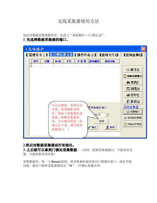
无线采集器使用方法
每次对数据采集器操作时,先进入“系统维护->门锁记录”。
1. 先选择数据采集器的端口。
可点击搜索,系统自动
寻找,如果搜索没响
应,则按下采集器任意
按钮,唤醒采集器再
试。
点击确定保存(如
果以后不变,则不用再
设置端口。
)
2.然后对数据采集器进行初始化。
3. 之后就可以拿到门锁处采集数据。
(对同一把锁采集数据后,不能再次采集,只能初始化再采集)
采集数据时,按一下Record按钮,将采集器的底部靠向门锁感应窗口,绿灯开始闪烁,最后门锁和采集器都发出“嘀”一声确认传输完毕。
4. 数据采集完毕后就可到“系统维护->门锁记录”处读取,点击“读无线采集器”后,会显示房间地址,点击对应的地址即可将记录显示。
点击“读无线采集
器”后,会显示房间
地址,点击对应的地
址即可读取。
- 1、下载文档前请自行甄别文档内容的完整性,平台不提供额外的编辑、内容补充、找答案等附加服务。
- 2、"仅部分预览"的文档,不可在线预览部分如存在完整性等问题,可反馈申请退款(可完整预览的文档不适用该条件!)。
- 3、如文档侵犯您的权益,请联系客服反馈,我们会尽快为您处理(人工客服工作时间:9:00-18:30)。
无
线
数
据
采
集
终
端
产品说明书
济南华通中控科技有限公司
HT-8系列户内数据采集终端
一、产品概述
HT-8系列户内数据采集终端,是根据本公司多年无线通信经验,本着安全、经济、合理、可靠的原则而设计的,具有数据采集、控制、保护、等多功能的新型户内采集设备,同时可根据用户要求加入模拟量测量等功能。
产品具有结构新颖、合理、防护等级高、安装调试、维护及检修方便等优点。
产品符合GB7251.1-1997,并通过了3C认证,是目前无线数据监测遥测理想的成套装置。
HT-8系列户内数据采集终端适用于无线数据采集,远程遥控遥测等多种应用。
二、产品特点
HT-8系列户内数据采集终端,有模拟量采集+控制,数字量采集+控制两种。
用户可根据需要选择不同方案,具体方案号如下:
01——模拟量采集+控制 02——数字量采集+控制
三、主要性能
1、监测及时迅速效果好,工作可靠。
2、保护功能:过压,量程超限等功能。
3、自动运行功能:停电退出、送电后自动恢复
四、运行条件
1、环境温度: -40℃~+55℃
2、空气相对湿度:≤90%(相对环境温度为20℃~25℃)
3、海拔高度:不超过2000m
4、环境条件:适用于箱体内安装,不适用于有火灾、爆炸危险、严重污秽、化学腐蚀及剧烈震
动的地方。
5、安装位置:与地面垂直的倾斜度不超过5º
五、技术参数:
1、额定电压:220V
2、额定频率:50Hz
六、安装调试
1、安装前检查
检查设备是否完好无损,随机资料及配件是否齐全,如发现问题应及时与厂家联系。
2、安装接线
1)产品安装于室内,固定牢固。
2)产品的安装由专业技术人员来完成严禁随意操作。
3、通电前的检查与实验
产品安装完毕后,投入运行前需进行如下项目的检查与实验。
1)检查箱体内是否干燥、清洁。
2)电器元件的操作机构是否灵活,不应有卡涩或操作力过大现象。
3)主要电器元件的通断是否可靠、准确,辅助接点的通断是否可靠准确。
4)PLC与通信模块指示是否正确。
5)用500伏兆欧表测量绝缘电阻不得低于10兆欧。
七、使用与维护注意事项
1)必须由合格的电气人员进行该产品的操作、维护和检修。
2)维修时要先断开电源再进行维修。
3)电缆进出处应采用可靠密封措施,确保运行安全。
4)空开应定期进行维修。
八、柜内元器件布置图。