13T.Q说明书-Model1
ESC POS指令手册说明书
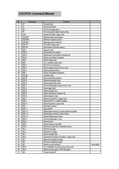
ESC/POS Command ManualCommand DescriptionsCommand Notation[Name]The name of the control command.[Format]The code sequence.In this description, < > H denotes hexadecimal numbers, < >denotesdecimal numbers and < > B denotes binary numbers.[ ] k indicates the contents of the [ ] should be repeated k times.[Range]The allowable range for the arguments.[Description]Description of the command function.[Details] If necessary provides important information on setting and using the printer command. [Default] The default values for the commands.[Reference]List related commands.[Example]Example of using the commands.The numbers denoted by <>H is hexadecimal.The numbers denoted by <>B is binary.Print CommandsThe WTP series supports the following commands for printing characters and advancingpaper.HT[Name] Horizontal tab[Format] ASCII HTHex 09Decimal 9[Description] Moves the print position to the next tab position.[Details] ·This command is ignored unless the next tab position has been set.·If the next horizontal tab position exceeds the printing area, the printersets the printing position to [Printing area width + 1].·Horizontal tab positions are set using “ESC D”.·If this command is received when the printing position is at [printing area width +1], the printerexecutes print buffer-full printing of the current line and horizontal tab processing from thebeginning of the next line.·The default setting of the horizontal tab position for the paper roll is font A(12 x 24) every 8th character (9th, 17th, 25th, … column).[Reference] ESC DLF[Name] Print and line feed[Format] ASCII LFHex 0ADecimal 10[Description] ·Prints the data in the print buffer and feeds one line based on the currentline spacing.[Details] ·This command sets the print position to the beginning of the line.[Reference] ESC 2, ESC 3CR[Name] Print and carriage return.[Format] ASCII CRHex 0DDecimal 13[Description] When automatic line feed is enabled, this command functions the same as LF; when automatic line feed is disabled, this command is ignored.[Details] ·Sets the print starting position to the beginning of the line.·The automatic line feed is ignored.[Reference] LFFF[Name] Print and return to standard mode in page mode.[Format] ASCII FFHex 0CDecimal 12[Description] Prints the data in the print buffer and returns to standard mode.[Details] ·The buffer data is deleted after being printed.·The printing area set by ESC W is reset to the default setting.·The printer does not execute paper cutting.·This command sets the print position to the beginning of the line.·This command is enabled only in page mode.[Reference] ESC FF, ESC L, ESC SCAN[Name] Cancel print data in page mode[Format] ASCII CANHex 18Decimal 24[Description] In page mode, delete all the print data in the current printable area. [Details] ·This command is enabled only in page mode.·If data that existed in the previously specified printable area also exists inthe currently specified printable area, it is deleted.[Reference] ESC L, ESC WDLE EOT n[Name] Real-time status transmission.[Format] ASCII DLE EOT nHex 10 04 nDecimal 16 4 n[Range] 1≤n≤4[Description] Transmits the selected printer status specified by n in real-time,according to the following parameters:n=1 : Transmit printer statusn=2 : Transmit off-line statusn=3 : Transmit error statusn=4 : Transmit paper roll sensor status[Details] ·The printer transmits the current status. Each status is represented byone-byte data.·The printer transmits the status without confirming whether the hostcomputer can receive data.·The printer executes this command upon receiving it.·This command is executed even when the printer is offline, the receivebuffer is full, or there is an error status.·When Auto Status Back (ASB) is enabled using the GS a command, thestatus transmitted by the DLE EOT command and the ASB status mustbe differentiated.·Even though the printer is not selected using ESC = (select peripheraldevice), this command is effective.[Notes] ·The status is transmitted whenever the data sequence of<10>H<04>H<n> (1≤n≤4) is received.Example :In ESC * m nL nH d1…dk d1=<10>H, d2=<04>H, d3=<01>H·This command should not be used within the data sequence of anothercommand that consists of 2 or more bytes.Example :If you attempt to transmit ESC 3 n to the printer, but DTR (DSR forthe host computer) goes to MARK before n is transmitted and thenDLE EOT 3 interrupts before n is received, the code <10> H for DLEEOT 3 is processed as the code for ESC 3 <10>H.correcting the cause of the error and executing DLE ENQ n (1 ≤ n ≤ 2). If an errordue to a circuit failure (e.g. wire break) occurs, it is impossible to recover.Bit 6: When printing is stopped due to high print head temperature until the print headtemperature drops sufficiently or when the paper roll cover is open during printing,bit 6 is On.[Reference] DLE ENQ, GS a, GS rDLE ENQ n[Name] Real-time request to printer[Format] ASCII DLE ENQ nHex 10 05 nDecimal 16 5 n[Range] 1≤n≤2[Description] Responds to a request from the host computer.[Details] ·When the printer is disabled with ESC = (Select peripheral device), thiscommand is effective.·This command is effective only when an auto-cutter error occurs.·The printer starts processing data upon receiving this command.·This command is executed even when the printer is offline, the receive buffer is full, or there isan error status with a serial interface model.·The status is also transmitted whenever the data sequence of <10>H<05>H< n> (1≤n≤2) isreceived.Example:In ESC * ** * m nL nH d k, d1 = <10>H, d2 = <05>H, d3 = <01>H·This command should not be contained within another command that consists of two or morebytes.Example:If you attempt to transmit ESC 3 n to the printer, but DTR (DSR for the host computer)goes to MARK before n is transmitted, and DLE ENQ 2 interrupts before n is received,the code <10>H for DLE ENQ 2 is processed as the code for ESC 3 <10>H. [Reference] DLE EOTDLE DC4 n m t[Name] Generate pulse at real-time[Format] ASCII DLE DC4 n m tHex 10 14 n m tDecimal 16 20 n m t[Range] n=1m=0,11≤t≤8[Description][Details] ·When the printer is in an error status when this command is processed,this command is ignored.·When the pulse is output to the connector pin specified while ESC p or DEL DC4 is executedwhile this command is processed, this command is ignored.·The printer executes this command upon receiving it.·This command is executed even when the printer is off-line, the receive buffer is full, or there is anerror status.·If print data includes the same character strings as this command, the printer performs the sameoperation specified by this command. The user must consider this.·This command should not be used within the data sequence of another command that consists of2 or more bytes.·This command is effective even when the printer is disabled with ESC = (Select peripheral device). [Reference] ESC pESC FF[Name] Print data in page mode[Format] ASCII ESC FFHex 1B 0CDecimal 27 12[Description] In page mode, prints all buffered data in the printable area collectively.[Details] ·This command is enabled only in page mode.·After printing, the printer does not clear the buffered data, setting value for ESC T and ESC W,and the position for buffering character data.[Reference] FF, ESC L, ESC SESC SP n[Name] Set right-side character spacing[Format] ASCII ESC SP nHex 1B 20 nDecimal 27 32 n[Range] 0≤n ≤255[Description] Sets the character spacing for the right side of the character to[n x horizontal or vertical motion units].[Details] ·The right-side character spacing for double-width mode is twice thenormal value. When characters are enlarged, the right-side characterspacing is n times normal value.·This command does not affect the setting of Kanji characters.·This command sets values independently in each mode (standard and page modes).·The horizontal and vertical motion units are specified by GS P.Changing the horizontal or vertical motion units does not affect the current right-side spacing.·The GS P command can change the horizontal (and vertical) motion unit. However, the valuecannot be less than the minimum horizontal movement amount, and it must be in even unitsof the minimum horizontal movement amount.·In standard mode, the horizontal motion unit is used.·In page mode, the horizontal or vertical motion unit differs in page mode, depending on startingposition of the printable area as follows:①When the starting position is set to the upper left or lower right of the printable area usingESC T, the horizontal motion unit (x) is used.②When the starting position is set to the upper right or lower left of the printable area usingESC T, the vertical motion unit (y) is used.·The maximum right-side spacing is 35.983 mm {255/180”}. Any setting exceeding the maximumis converted to the maximum automatically.[Default] n = 0[Reference] GS PESC ! n[Name] Select print mode(s)[Format] ASCII ESC ! nHex 1B 21 nDecimal 27 33 n[Range]0≤n ≤255[Description] Selects print mode(s) using n as follows:[Details] ·When both double-height and double-width modes are selected,quadruple size characters are printed.·The printer can underline all characters, but can not underline the space set by HT or 90clockwise rotated characters.·The thickness of the underline is selected by ESC-, regardless of the character size.·When some characters in a line are double or more height, all the characters on the line arealigned at the baseline.·ESC E Can also turn on or off emphasized mode. However, the setting of the last receivedcommand is effective.·ESC -Can also turn on or off underline mode. However, the setting of the last receivedcommand effective.·GS ! Can also select character size, However, the setting of the last received command iseffective.·Emphasized mode is effective for alphanumeric and Kanji. All print modes except emphasizedmode is effective only for alphanumeric.[Default] n = 0[Reference] ESC E, ESC -, GS !ESC $ n L n H[Name] Set absolute print position[Format] ASCII ESC $ n L n HHex 1B 24 n L n HDecimal 27 36 n L n H[Range] 0≤nL≤2550≤nH≤255[Description] Sets the distance from the beginning of the line to the position at which subsequent characters are to be printed.[Details] ·The distance from the beginning of the line to the print position is[(n L + n H x 256) x (vertical or horizontal motion unit)] inches.·Settings outside the specified printable area are ignored.·The horizontal and vertical motion units are specified by “GS P”.·The GS P command can change the horizontal (and vertical) motion unit.However, the value cannot be less than the minimum horizontal movement amount, and itmust be in even units of the minimum horizontal movement amount. In standard mode, thehorizontal motion unit is used.·In page mode, the horizontal or vertical motion unit differs depending on the starting position ofthe printable area as follows :1. When the starting position is set to the upper left or lower right of the printable areausing ESC T, the horizontal motion unit (x) is used.2. When the starting position is set to the upper right or lower left of the printable areausing ESC T, the vertical motion unit (y) is used.[Reference] ESC \, GS $, GS \, GS PESC % n[Name] Select/cancel user-defined character set[Format] ASCII ESC % nHex 1B 25 nDecimal 27 37 n[Range] 0≤n ≤255[Description] Selects or cancels the user-defined character set·When the LSB of n is 0, the user-defined character set is canceled.·When the LSB of n is 1, the user-defined character set is selected.[Details] ·When the user-defined character set is canceled, the internal characterset is automatically selected.·n is available only for the least significant bit.[Default] n = 0[Reference] ESC &, ESC ?ESC & y c1 c2 [x1 d1…d(y x x1)]..[ xk d1..d(y x xk)][Name] Define user-defined characters[Format] ASCII ESC & y c1 c2 [x1 d1...d(y ⨯ x1)]...[xk d1...d(y ⨯ xk)]Hex 1B 26 y c1 c2 [x1 d1...d(y ⨯ x1)]...[xk d1...d(y ⨯ xk)]Decimal 27 38 y c1 c2 [x1 d1...d(y ⨯ x1)]...[xk d1...d(y ⨯ xk)][Range] y = 332 ≤c1≤c2≤ 1260 ≤ x ≤ 12 Font A (when font A (12 x 24) is selected)0 ≤ x ≤ 9 Font B (when font B (9 x 17) is selected)0 ≤ d1 ... d(y x x k) ≤ 255[Description] Defines user-defined characters·y specifies the number of bytes in the vertical direction.·c1 specifies the beginning character code for the definition, and c2 specifies the final code.·X specifies the number of dots in the horizontal direction.[Details] ·The allowable character code range is from ASCII code <20>H to<7E>(95characters).·It is possible to define multiple characters for consecutive character codes.·If only one character is desired, use c1 = c2.·d is the dot data for the characters. The dot pattern is in the horizontal direction from the leftside. Any remaining dots on the right side are blank.·The data to define a user-defined character is (y ⨯ x) bytes.·Set a corresponding bit to 1 to print a dot or 0 to not print a dot.·This command can define different user-defined character patterns by each fonts. To select afont, use ESC !·A user-defined character and a downloaded bit image cannot be defined simultaneously. Whenthis command is executed, the downloaded bit image is cleared.·The user-defined character definition is cleared when:①ESC @ is executed.②ESC ? is executed.③FS q is executed.④GS * is executed.⑤ The printer is reset or the power is turned off.·When the user-defined characters are defined in font B (9 x 24), only the most significant bit ofthe 3rd byte of data in vertical direction is effective.ESC *m n L n H [d1...dk][Name] Select bit-image mode[Format] ASCII ESC *m n L n H d1...dkHex 1B 2A m n L n H d1...dkDecimal 27 42 m n L n H d1...dk[Range] m = 0, 1, 32, 330≤n L ≤2550≤n H ≤30≤d ≤255[Details] ·If the values of m is out of the specified range, nL and data following areprocessed as normal data.·The nL and nH indicate the number of dots of the bit image in the horizontal direction. Thenumber of dots is calculated by nL + nH x 256.·If the bit-image data input exceeds the number of dots to be printed on a line, the excess data isignored.·d indicates the bit-image data. Set a corresponding bit of 1 to print a dot or to 0 to not print a dot.·If the width of the printing area set by GS L and GS W less than the width required by the datasent with the ESC *command the following will be performed on the line in question (but theprinting cannot exceed the maximum printable area) :① The width of the printing area is extended to the right to accommodate the amount ofdata.② If step ① does not provide sufficient width for the data, the left margin is reduced toaccommodate the data.·After printing a bit image, the printer returns to normal data processing mode.·This command is not affected by print modes(emphasized, double-strike, underline, charactersize or white/black reverse printing), except upside-down printing mode.·Refer to Figure 3.12.3 for the bit image development position in page mode.·The relationship between the image data and the dots to be printed is as follows:·When 8-dot bit image is selected:ESC - n[Name] Turn underline mode on/off[Format] ASCII ESC - nHex 1B 2D nDecimal 27 45 n[Range] 0≤n ≤2, 48≤n ≤50[Details] ·The printer can underline all characters (including right-side characterspacing), but cannot underline the space set by HT.·The printer cannot underline 90˚ clockwise rotated characters and white/black invertedcharacters.·When underline mode id turned off by setting the value of n to 0 or 48, the following data is notunderlined, and the underline thickness set before the mode is turned off does not change.The default underline thickness is 1 dot.·Changing the character size does not affect the current underline thickness.·Underline mode can also be turned on or off by using ESC!. Note, however, that the lastreceived command is effective.·This command does not affect Kanji printing.[Default] n = 0[Reference] ESC !ESC 2[Name] Select default line spacing[Format] ASCII ESC 2Hex 1B 32Decimal 27 50[Description] Selects approximately 4.23 mm {1/6”} spacing.[Details] ·The line spacing can be set independently in standard mode and inpage mode.[Reference] ESC 3ESC 3 n[Name] Set line spacing[Format] ASCII ESC 3 nHex 1B 33nDecimal 27 51 n[Range] 0≤n ≤255[Description] Sets the line spacing to [n x (vertical or horizontal motion unit)] inches.[Details] ·The line spacing can be set independently in standard mode and inpage mode.·The horizontal and vertical motion unit is specified by GS P.Changing the horizontal or vertical motion unit does not affect the current line spacing.·The GS P command can change the horizontal (and vertical) motion unit.However, the value cannot be less than the minimum vertical movement amount, and it mustbe in even units of the minimum vertical movement amount.·In standard mode, the vertical motions until (y) is used.·In page mode, this command function as follows, depending on thestarting position of the printable area :①When the starting position is set to the upper left or lower right to the printable areausing ESC T, the vertical motion unit (y) is used.②When the starting position is set to the upper right or lower left ofthe printable area using ESC T, the horizontal motion unit (x) is used.·The maximum paper feed amount is 1016 mm {40”}. Even if a paper feed amount of more than1016 mm{40”}is set, the printer feeds the paper only 1016 mm{40”}[Default] Line space is equivalent to approximately 4.23 mm{1/6”}.[Reference] ESC 2, GS PESC = n[Name] Set peripheral device[Format] ASCII ESC = nHex 1B 3D nDecimal 27 61 n[Range] 1≤n ≤255[Description] Selects device to which host computer sends data, using n as follows:[Details] ·When the printer is disabled, it ignores all data except for error-recoverycommands (DLE EOT, DLE ENQ, DLE DC4) until it is enabled by this command. [Default] n=1ESC ? n[Name] Cancel user-defined characters[Format] ASCII ESC ? nHex 1B 3F nDecimal 27 63 n[Range] 32 ≤n ≤126[Description] Cancels user-defined characters.[Details] ·This command cancels the pattern defined for the character codespecified by n. After the user-defined characters is canceled, the corresponding pattern for theinternal character is printed.·This command deletes the pattern defined for the specified code in thefont selected by ESC !.·If a user-defined character has not been defined for the specifiedcharacter code, the printer ignores this command.[Reference] ESC &, ESC %ESC @[Name] Initialize printer[Format] ASCII ESC @Hex 1B 40Decimal 27 64[Description] Clears the data in the print buffer and resets the printer mode to the modethat was in effect when the power was turned on.[Details] ·The DIP switch settings are not checked again.·The data in the receive buffer is not cleared.·The macro definition is not cleared.·The NV bit image data is not cleared.·The data of the NV user memory is not cleared.ESC D [n1...nk] NUL[Name] Set horizontal tab positions[Format] ASCII ESC D n1……nk NULHex 1B 44 n1……nk 00Decimal 27 68 n1……nk 0[Range] 1≤n ≤2550≤k ≤32[Description] Set is horizontal tab positions.·n specifies the column number for setting a horizontal tab position from the beginning of the line.·k indicates the total number of horizontal tab positions to be set.[Details] ·The horizontal tab position is stored as a value of [character width x n]measured from the beginning of the line. The character width includes the right-side characterspacing, and double-width characters are set with twice the width of normal characters.·This command cancels the previous horizontal tab settings.·When setting n = 8, the print position is moved to column 9 by sending HT.·Up to 32 tab positions (k=32) can be set. Data exceeding 32-tab positions s is processed asnormal data.·Transmit [n]k in ascending order and place a NUL code 0 at the end.·When [n]k is less than or equal to the preceding value [n]k-1, tab setting is finished and thefollowing data is processed as normal data,·ESC D NUL cancels all horizontal tab positions.·The previously specified horizontal tab positions do not change, even if the character widthchanges.·The character width is memorized for each standard and page mode.[Default] The default tab positions are at intervals of 8 characters (columns 9, 17, 25, ...) for the font A (12 X 24).[Reference] HTESC E n[Name] Turn emphasized mode on/off[Format] ASCII ESC E nHex 1B 45 nDecimal 27 69 n[Range] 0≤n ≤255[Description] Turns emphasized mode on or off.·When the LSB of n is 0, emphasized mode is turned off.·When the LSB of n is 1, emphasized mode is turned on.[Details] ·Only the least significant bit of n is enabled.·This command and ESC! Turn on and off emphasized mode in the same way. Be careful whenthis command is used with ESC!.[Default] n = 0[Reference] ESC !ESC G n[Name] Turn on/off double-strike mode[Format] ASCII ESC G nHex 1B 47 nDecimal 27 71 n[Range] 0≤n ≤255[Description] Turns double-strike mode on or off.·When the LSB of n is 0, double-strike mode is turned off.·When the LSB of n is1, double-strike mode is turned on.[Details] ·Only the lowest bit of n is enabled.·Printer output is the same in double-strike mode and in emphasized mode.[Default] n = 0[Reference] ESC EESC J n[Name] Print and feed paper[Format] ASCII ESC J nHex 1B 4A nDecimal 27 74 n[Range] 0≤n ≤255[Description] Prints the data in the print buffer and feeds the paper [n x vertical or horizontal motion unit]. [Details] ·After printing is completed, this command sets the print starting positionto the beginning of the line.·The paper feed amount set by this command does not affect the values set by ESC 2 or ESC 3.·The horizontal and vertical motion unit is specified by GS P.·The GS P command can change the vertical (and horizontal) motion unit.However, the value cannot be less than the minimum vertical movement, and it must be ineven units of the minimum vertical movement amount.·In standard mode, the printer uses the vertical motion unit(y).·In page mode, this command functions as follows, depending on the starting position of theprintable area.①When the starting position is set to the upper left or lower right of the printable areausing ESC T, the vertical motion unit (y) is used.②When the starting position is set to the upper right or lower left of the printable areausing ESC T, the horizontal motion unit (x) is used.·The maximum line spacing is 1016 mm{40”}. When the setting value exceeds the maximum, it isconverted to the maximum automatically.[Reference] GS PESC L[Name] Select page mode[Format] ASCII ESC LHex 1B 4CDecimal 27 76[Description] Switches from standard mode to page mode.[Details] ·This command is enabled only when input at the beginning of a line instandard mode.·This command has no effect in page mode.·After printing by FF is completed or by using ESC S, the printer returns to standard mode.·This command sets the position where data is buffered to the position specified by ESC T withinthe printing area defined by ESC W.·This command is switches the setting for the following commands (in which the values can beset independently in standard mode and page mode) to those for page mode.① Set right-side character spacing : ESC SP, FS S②Select default line spacing : ESC 2, ESC3·Only valve settings is possible for the following commands in pagemode; these commands are not executed.① Turn 90 clockwise rotation mode on/off: ESC V② Select justification: ESC a③ Turn upside-down printing mode on/off: ESC {④ Set left margin: GS L⑤ Set printable area width: GS W·The following command is ignored in page mode:①Execute test print: GS W·The following command is not available in page mode:①Print NV bit image : FS p②Define NV bit image : FS q③Print raster bit image : GS v 0·The printer returns to standard mode when power is turned on, the printer is reset, or ESC @ isused.[Reference] FF, CAN, ESC FF, ESC S, ESC T, ESC W, GS $, GS \ESC M n[Name] Select character font[Format] ASCII ESC M nHex 1B 4D nDecimal 27 77 n[Range] n= 0, 1 , 48, 49[Description] Selects character fonts[Details] ·The ESC ! command can also select the character fonts. However, thesetting of the last received command is effective. [Reference] ESC !ESC R n[Name] Select an international character set[Format] ASCII ESC R nHex 1B 52 nDecimal 27 82 n[Range] 0≤n ≤13[Description][Default] n = 0[Reference] 3.2.12 International Character SetESC S[Name] Select standard mode[Format] ASCII ESC SHex 1B 53Decimal 27 83[Description] Switches from page mode to standard mode.[Details] ·This command is effective only in page mode.·Data buffered in page mode and the printable area developed in page mode are cleared.·This command is switches the setting for the following command (in which the values can be setindependently in standard mode and page mode) to those for standard mode:① Set right-side character spacing: ESC SP, FS S② Select default line spacing : ESC 2, ESC 3·The following commands are enabled only to set in standard mode.① Set printing area in page mode : ESC W② Set print direction in page mode : ESC T·The following commands are ignored in standard mode.①Set absolute vertical print position in page mode : GS $②Set relative vertical print position in page mode : GS \·Standard mode is selected automatically when power is turned on, the。
InstantFit LED灯泡兼容性说明说明书

This is real compatibilityOther lamps claim compatibility, but only InstantFit has been proven to work with 50% more ballasts 1 delivering even light output, proven energy savings and a long average lifetime. That’s true compatibility.• InstantFit works with over 200 ballasts — more than any other lamp — so you know it’s going to perform as expected and keep you from having to redo any jobs • Proven over 40% energy savings 2 over fluorescent means a satisfied customer and no time wasted going back to a job• Lifetime delivered — average life rating of 50,000 hours 3, with up to 70,0003 in the portfolio, means satisfied customers• Improved profit and more time growing business instead of doing rework• Light quality and performance predictability—consistent light output and no flicker means satisfied happy customers and no wasted time redoing a job.• Proven product history and a company with a long history of innovation and reliability in the lighting industry.InstantFit lampsLEDSee footnotes on last page.Ordering, electrical and technical data (Subject to change without notice)Product Number Model Number(s)DLC Product ID 8Ordering CodeVolts (Depending on Ballast)Base CRI Color Temp. (K)Pkg Qty LED Lifetime 4MOL (In.)Beam Angle InstantFit LED T8 - 4'InstantFit LED T8 - 4' high output glass 47009-69290013430Pending 14T8 PRO LED/48-3000 IF G 10/1120-277, 347 G13 8230001050,00048240°47010-49290013431PV2NCR1M 14T8 PRO LED/48-3500 IF G 10/1120-277, 347 G13 8235001050,00048240°47011-29290013432PUQ8ZEAH 14T8 PRO LED/48-4000 IF G 10/1120-277, 347 G13 8240001050,00048240°47012-09290013433P8HU6SVS 14T8 PRO LED/48-5000 IF G 10/1120-277, 347 G13 8250001050,00048240°InstantFit LED T8 - 4' ultra high output 46313-39290012267PNGUXZUY 16.5T8 LED/48-3500 IF 10/1 UHO 120-277, 347G1382350010 70,000 48160°46314-19290012268PZ5C8FWR 16.5T8 LED/48-4000 IF 10/1 UHO 120-277, 347G1382400010 70,000 48160°46315-89290012269PS8REP3K 16.5T8 LED/48-5000 IF 10/1 UHO 120-277, 347G1382500010 70,000 48160°InstantFit LED T8 - 4'glass 45656-69290011511Not DLC Certified 17T8/48-4000 IFG 10/1120-277, 347G138240001036,00048240°45657-49290011512Not DLC Certified 17T8/48-5000 IFG 10/1120-277, 347G138250001036,00048240°InstantFit LED T8 - 3'46932-09290013113No DLC Category 9T8 LED/36-3000 IF 10/1120-277, 347G138230001050,00036160°46933-89290013114No DLC Category 9T8 LED/36-3500 IF 10/1120-277, 347G138235001050,00036160°46934-69290013115No DLC Category 9T8 LED/36-4000 IF 10/1120-277, 347G138240001050,00036160°46935-39290013116No DLC Category 9T8 LED/36-5000 IF 10/1120-277, 347G138250001050,00036160°InstantFit LED T8 - 2' high output 46927-09290013108Not DLC Certified 7T8 LED/24-3000 IF 10/1120-277, 347G138230001050,00024160°46928-89290013109PM745MKV 7T8 LED/24-3500 IF 10/1120-277, 347G138235001050,00024160°46929-69290013110PKTG4YER 7T8 LED/24-4000 IF 10/1120-277, 347G138240001050,00024160°46930-49290013111PW99TC5B 7T8 LED/24-5000 IF 10/1120-277, 347G138250001050,00024160°InstantFit LED T8/T12 - 8'46923-99290013077No DLC Category 35T8/96-3000 IF FA8 10/1120-277, 347FA88230001050,00096160°46924-79290013078No DLC Category 35T8/96-3500 IF FA8 10/1120-277, 347FA88235001050,00096160°46925-49290013146No DLC Category 35T8/96-4000 IF FA8 10/1120-277, 347FA88240001050,00096160°46926-29290013147No DLC Category 35T8/96-6500 IF FA8 10/1120-277, 347FA88265001050,00096160°InstantFit LED T5 high output 46712-69290012837Not DLC Certified 24T5 LED/HO/48-3000 IF 10/1120-277, 347-480V G58230001050,00046160°46713-49290012838PR7H998W 24T5 LED/HO/48-3500 IF 10/1120-277, 347-480V G58235001050,00046160°46714-29290012839PUFNVUMP 24T5 LED/HO/48-4000 IF 10/1120-277, 347-480V G58240001050,00046160°46715-99290012840PJHYX3QV 24T5 LED/HO/48-5000 IF 10/1120-277, 347-480V G58250001050,00046160°InstantFit LED T8 U-Bent - 6" high output 46937-99290013118PTESWFZT 13T8 LED/24-3000 IF-6U 10/1120-277, 347G138230001050,00024160°46938-79290013119P14MK6P713T8 LED/24-3500 IF-6U 10/1120-277, 347G138235001050,00024160°46939-59290013120P3WDMMYN 13T8 LED/24-4000 IF-6U 10/1120-277, 347G138240001050,00024160°46940-39290013121PSR46S6R 13T8 LED/24-5000 IF-6U 10/1120-277, 347G138250001050,00024160°LED InstantFit - 4' rotatable high output 46865-29290013033P1Z3VUZP 14T8/48-3000 IF 10/1 ROT 120-277, 347G138230001050,00048160°46866-09290013034PMRXKRUT 14T8/48-3500 IF 10/1 ROT 120-277, 347G138235001050,00048160°46867-89290013035P2R73QWZ 14T8/48-4000 IF 10/1 ROT 120-277, 347G138240001050,00048160°46868-69290013036PQ2TMYAQ14T8/48-5000 IF 10/1 ROT120-277, 347G138250001050,00048160°See footnotes on last page.Please refer to /instantfit for instant start ballasts details and the latest ballast compatibility guide 5. For more information on Philips’ limited warranty please visit /warranties.Many lamps claim compatibility. InstantFit proves it.Product Number Bare Lamp Watts(W)Average System Watts (W)Initial Lumens6Low BallastFactor (0.78)Normal BallastFactor (0.88)High BallastFactor (1.18)Low BallastFactor (0.78)Normal BallastFactor (0.88)High BallastFactor (1.18)InstantFit LED T8 - 4'46826-4 10.011.013.016.013001500170046827-2 10.011.013.016.013001500180046828-0 10.011.013.016.014001600185046829-8 10.011.013.016.014001600185046956-9 10.011.013.016.013001500170046957-7 10.011.013.016.013001500180046958-5 10.011.013.016.014001600185046959-3 10.011.013.016.0140016001850InstantFit LED T8 - 4' dimmable high output46830-614.015.017.023.018002000270046831-414.015.017.023.018002000270046832-214.015.017.023.019002100280046833-014.015.017.023.019002100280046960-114.015.017.023.018002000270046961-914.015.017.023.018002000270046962-714.015.017.023.019002100280046963-514.015.017.023.0190021002800InstantFit LED T8 - 4' high output glass47009-614.015.017.023.017502000235047010-414.015.017.023.017502000235047011-214.015.017.023.018502100245047012-014.015.017.023.0185021002450s InstantFit LED T8 - 4' ultra high output46313-316.518.020.027.022002400295046314-116.518.020.027.022502500305046315-816.518.020.027.0225025003050InstantFit LED T8 - 4' glass45656-617.018.020.026.518502100245045657-417.018.020.026.5185021002450InstantFit LED T8 - 3'46932-09.010.511.515.59501100130046933-89.010.511.515.59501100130046934-69.010.511.515.510501200140046935-39.010.511.515.5105012001400InstantFit LED - 2' high output46927-07.0 8.5 9.5 13.59501050120046928-87.0 8.5 9.5 13.59501050120046929-67.0 8.5 9.5 13.510501150130046930-47.0 8.5 9.5 13.5105011501300InstantFit LED T8/T12 - 8'46923-935.0 N/A 41.0 N/A N/A4000N/A46924-735.0 N/A 41.0 N/A N/A4000N/A46925-435.0 N/A 41.0 N/A N/A4200N/A46926-235.0 N/A 41.0 N/A N/A4200N/AInstantFit LED T5 high output46712-624.0 N/A 28.0 N/A N/A3300N/A46713-424.0 N/A 28.0 N/A N/A3300N/A46714-224.0 N/A 28.0 N/A N/A3500N/A46715-924.0 N/A 28.0 N/A N/A3500N/AInstantFit LED T8 U-Bent - 6" high output46937-913.014.016.021.018002000270046938-713.014.016.021.018002000270046939-513.014.016.021.019002100280046940-313.014.016.021.0190021002800LED InstantFit - 4' dimmable rotatable high output46865-214.015.0 17.0 23.018002000270046866-014.015.0 17.0 23.018002000270046867-814.015.0 17.0 23.019002100280046868-614.015.0 17.0 23.0190021002800 Ballast technical data (Subject to change without notice)See footnotes on last page. Many lamps claim compatibility. InstantFit proves it.Ordering, electrical and technical data (Subject to change without notice)Ballast technical data (Subject to change without notice)ProductNo.Model No.Ordering CodeVolts (Dependingon Ballast)Base CRIColor Temp.(K)LED Liftetime(hrs.)4MOL(In.)BeamAngle InstantFit LED T8 EM compatible5 – 4' glass46311-7929001226520T12 EM LED/48-4000 IF G 120-277G1383400036,00048240°46312-5929001226620T12 EM LED/48-6500 IF G120-277G1383650036,00048240°Suitable for use in fixtures where ambient temperature is between -4°F (-20°C) and 113°F (45°C).ProductNo.Bare Lamp Watts(W)Average System Watts (W)Initial Lumens4Low Ballast Factor(0.78)Normal BallastFactor (0.88)High Ballast Factor(1.18)Low BallastFactor (0.78)Normal BallastFactor (0.88)High Ballast Factor(1.18) InstantFit LED T8 EM compatible – 4' glass46311-720202331 185021002800 46312-52020 2331185021002800System wattage of the Philips InstantFit T8 vs a comparable linear T127Ballast Model No.Manufacturer System Voltage No. of Lamps System Power (W) T12 Fluorescent System Power (W) T8 LED Energy Savings (%)9 R-140-1-TP Philips Advance120152.126.150.0%RL-140-TP Philips Advance120132.825.621.7%R-2S40-1-TP Philips Advance120288.947.147.0% XQM-2S40-TP Philips Advance220295.551.945.6%V-2S40-1-TP Philips Advance277290.245.349.8% RQM-2S40-3-TP Philips Advance120286.946.446.6%R-2S34-TP-5Philips Advance120281.141.548.8%V-2S34-TP Philips Advance277279.242.646.3%RM-2S35-TP Philips Advance120260.941.232.4%See footnotes on last page.Philips InstantFit LED T8 electro magnetic compatible lampsShipping data (Subject to change without notice)ProductNumberSKU UPC(0-46677)Outer Bar Code(5-00-46677)CaseQty.Case Weight(lbs.)Case Cube(cu. Ft.)PalletQtyLamps/SKUSKUsperLayerLayersHighSKU Dimensions(L x W x H) (In.)Case Dimensions(L x W x H) (In.)Pallet Dimensions(L x W x H) (In.)InstantFit LED T8 - 4'46826-447219-146826-710 6.20.4211201701648.0 x 1.1 x 1.149.3 x 5.5 x 2.750.4 x 39.4 x 48.746827-247220-746827-410 6.20.4211201701648.0 x 1.1 x 1.149.3 x 5.5 x 2.750.4 x 39.4 x 48.746828-047221-446828-110 6.20.4211201701648.0 x 1.1 x 1.149.3 x 5.5 x 2.750.4 x 39.4 x 48.746829-847222-146829-810 6.20.4211201701648.0 x 1.1 x 1.149.3 x 5.5 x 2.750.4 x 39.4 x 48.746956-947260-346956-1109.70.606001601048.0 x 1.1 x 1.148.8 x 6.0 x 3.549.2 x 39.4 x 40.946957-747261-046957-8109.70.606001601048.0 x 1.1 x 1.148.8 x 6.0 x 3.549.2 x 39.4 x 40.946958-547262-746958-5109.70.606001601048.0 x 1.1 x 1.148.8 x 6.0 x 3.549.2 x 39.4 x 40.946959-347263-446959-2109.70.606001601048.0 x 1.1 x 1.148.8 x 6.0 x 3.549.2 x 39.4 x 40.9InstantFit LED T8 - 4' dimmable high output46830-647223-846830-410 6.20.4211201701648.0 x 1.1 x 1.149.3 x 5.5 x 2.750.4 x 39.4 x 48.746831-447224-546831-110 6.20.4211201701648.0 x 1.1 x 1.149.3 x 5.5 x 2.750.4 x 39.4 x 48.746832-247225-246832-810 6.20.4211201701648.0 x 1.1 x 1.149.3 x 5.5 x 2.750.4 x 39.4 x 48.746833-047226-946833-510 6.20.4211201701648.0 x 1.1 x 1.149.3 x 5.5 x 2.750.4 x 39.4 x 48.746960-147264-146960-8109.70.606001601048.0 x 1.1 x 1.148.8 x 6.0 x 3.549.2 x 39.4 x 40.946961-947265-846961-5109.70.606001601048.0 x 1.1 x 1.148.8 x 6.0 x 3.549.2 x 39.4 x 40.946962-747266-546962-2109.70.606001601048.0 x 1.1 x 1.148.8 x 6.0 x 3.549.2 x 39.4 x 40.946963-547267-246963-9109.70.606001601048.0 x 1.1 x 1.148.8 x 6.0 x 3.549.2 x 39.4 x 40.9InstantFit LED T8 - 4' high output glass47009-645240-747009-310 6.20.425501501648.0 x 1.1 x 1.149.5 x 7.1 x 3.950.6 x 39.4 x 48.347010-445275-947010-910 6.20.425501501648.0 x 1.1 x 1.149.5 x 7.1 x 3.950.6 x 39.4 x 48.347011-245325-147011-610 6.20.425501501648.0 x 1.1 x 1.149.5 x 7.1 x 3.950.6 x 39.4 x 48.347012-045248-347012-310 6.20.425501501648.0 x 1.1 x 1.149.5 x 7.1 x 3.950.6 x 39.4 x 48.3InstantFit LED T8 - 4' ultra high output46313-346313-746313-2109.70.5960016010 1.1 x 1.1 x 48.048.8 x 6.0 x 3.549.2 x 39.4 x 40.946314-146314-446314-9109.70.5960016010 1.1 x 1.1 x 48.048.8 x 6.0 x 3.549.2 x 39.4 x 40.946315-846315-146315-6109.70.5960016010 1.1 x 1.1 x 48.048.8 x 6.0 x 3.549.2 x 39.4 x 40.9InstantFit LED T8 - 4' glass45656-645656-645656-110 9.7 1.0636014010 1.1 x 1.1 x 48.049.8 x 8.8 x 4.251.2 x 39.4 x 43.445657-445657-345657-8 10 9.7 1.0636014010 1.1 x 1.1 x 48.049.8 x 8.8 x 4.251.2 x 39.4 x 43.4InstantFit LED T8 - 3'46932-047231-346932-510 4.50.3114401901635.7 x 1.0 x 1.037.1 x 5.4 x 2.750.6 x 39.4 x 48.646933-847232-046933-210 4.50.3114401901635.7 x 1.0 x 1.037.1 x 5.4 x 2.750.6 x 39.4 x 48.646934-647233-746934-910 4.50.3114401901635.7 x 1.0 x 1.037.1 x 5.4 x 2.750.6 x 39.4 x 48.646935-347234-446935-610 4.50.3114401901635.7 x 1.0 x 1.037.1 x 5.4 x 2.750.6 x 39.4 x 48.6InstantFit LED T8 - 2' high output46927-047227-646927-110 2.60.23224011401623.7 x 1.0 x 1.025.3 x 5.8 x 2.751.1 x 39.4 x 48.646928-847228-346928-810 2.60.23224011401623.7 x 1.0 x 1.025.3 x 5.8 x 2.751.1 x 39.4 x 48.646929-647229-046929-510 2.60.23224011401623.7 x 1.0 x 1.025.3 x 5.8 x 2.751.1 x 39.4 x 48.646930-447230-646930-110 2.60.23224011401623.7 x 1.0 x 1.025.3 x 5.8 x 2.751.1 x 39.4 x 48.6InstantFit LED T8/T12 - 8'46923-946923-846923-31016.7 2.06300130100.0 x 0.0 x 0.095.9 x 9.4 x 3.996.4 x 29.9 x 45.246924-746052-546052-01016.7 2.06300130100.0 x 0.0 x 0.095.9 x 9.4 x 3.996.4 x 29.9 x 45.246925-446925-246925-71016.7 2.06300130100.0 x 0.0 x 0.095.9 x 9.4 x 3.996.4 x 29.9 x 45.246926-246926-946926-41016.7 2.06300130100.0 x 0.0 x 0.095.9 x 9.4 x 3.996.4 x 29.9 x 45.2InstantFit LED T5 high output46712-646712-846712-310 4.70.2220001100200.0 x 0.0 x 0.046.3 x 4.0 x 2.147.2 x 40.6 x 47.646713-446713-546713-010 4.70.2220001100200.0 x 0.0 x 0.046.3 x 4.0 x 2.147.2 x 40.6 x 47.646714-246714-246714-710 4.70.2220001100200.0 x 0.0 x 0.046.3 x 4.0 x 2.147.2 x 40.6 x 47.646715-946715-946715-410 4.70.2220001100200.0 x 0.0 x 0.046.3 x 4.0 x 2.147.2 x 40.6 x 47.6InstantFit LED U-Bent - 6" high output46937-947235-146937-0108.2 1.203001100322.4 x 7.1 x 1.123.1 x 7.5 x 11.947.2 x 39.4 x 41.446938-747236-846938-7108.2 1.203001100322.4 x 7.1 x 1.123.1 x 7.5 x 11.947.2 x 39.4 x 41.446939-547237-546939-4108.2 1.203001100322.4 x 7.1 x 1.123.1 x 7.5 x 11.947.2 x 39.4 x 41.446940-347238-246940-0108.2 1.203001100322.4 x 7.1 x 1.123.1 x 7.5 x 11.947.2 x 39.4 x 41.4LED InstantFit - 4' rotatable high output46865-247268-946865-610 6.20.421120170160.0 x 0.0 x 0.049.3 x 5.5 x 2.750.4 x 39.4 x 48.746866-047269-646866-310 6.20.421120170160.0 x 0.0 x 0.049.3 x 5.5 x 2.750.4 x 39.4 x 48.746867-847270-246867-010 6.20.421120170160.0 x 0.0 x 0.049.3 x 5.5 x 2.750.4 x 39.4 x 48.746868-647271-946868-710 6.20.421120170160.0 x 0.0 x 0.049.3 x 5.5 x 2.750.4 x 39.4 x 48.7See footnotes on last page. Many lamps claim compatibility. InstantFit proves it.Shipping Data (Subject to change without notice)Product NumberSKU UPC (0-46677)Outer Bar Code (5-00-46677)Case Qty.Case Weight (lbs.)Case Cube (cu. Ft.)Pallet Qty Lamps/SKUSKUs per Layer Layers High SKU Dimensions (W x D x H) (In.)Case Dimensions(W x D x H) (In.)Pallet Dimensions (W x D x H) (In.)InstantFit LED T8 EM compatible - 4' glass 46311-746311-346311-810 6.26 1.063601409 1.1 x 1.1 x 48.049.8 x 8.8 x 4.251.2 x 39.4 x 43.446312-546312-046312-5106.261.0636014091.1 x 1.1 x 48.049.8 x 8.8 x 4.251.2 x 39.4 x 43.44' T8 Lamps – 0.88 BF Ballast Ambient Temperature (°C)R e l a t i v e L u m e n s (%)101025W Relative light output with respect to 25˚C rated temperature203040506070203040506070809010011012028W 32W T8InstantFit TLEDSuitable for use in fixtures where ambient temperature is between -4°F (-20°C) and 113°F (45°C).Warning: Philips LED T8 InstantFit lamps will only operate properly on compatible Instant-start and Programmed-start ballasts. Please refer to the Philips LED T8 InstantFit Installation Guide, which can be obtained through your local Philips Sales Representative, or visit /instantfitFCC Note: This device complies with Part 18 of the FCC Rules.Relative Light Output vs. Ambient Temperature4' T8 Lamps - 0.88 BF Ballast。
格兰富高压水泵说明书
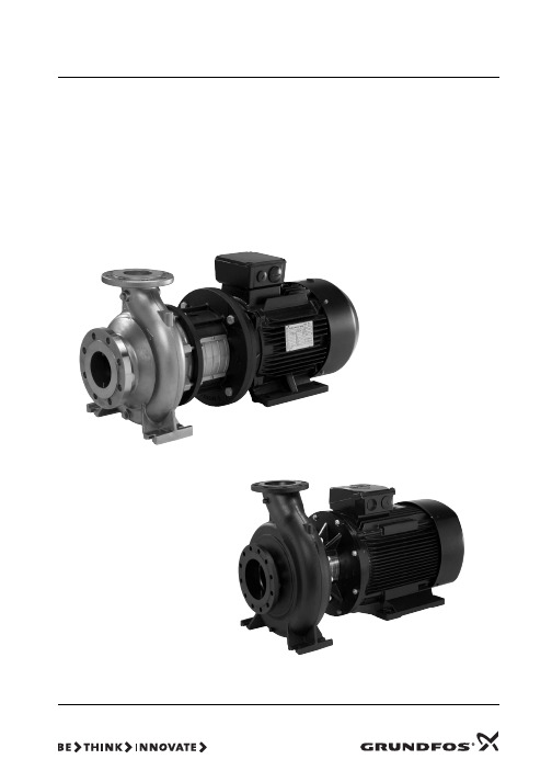
重量: 见包装箱上的标签。
警告 泵配电机4 kw以上配有吊装环,但此吊装环不能用来 起吊整个泵。 见图4。 应使用尼龙带和扣环或吊钩来吊装水泵,如图1到3所示。
图 3 不带电机水泵的正确吊装
TM05 3309 1112
TM03 3972 1306
TM03 3973 1306
96145329
青铜/黄铜
1.4301/1.4308
C EN-GJL-250
EN-GJL-200
青铜/黄铜
1.4401/1.4408
D EN-GJL-250
青铜 CuSn10
青铜/黄铜
1.4401/1.4408
E EN-GJL-250
EN-GJL-200
EN-GJL-250
9. 法兰受力与力矩
10. 电气连接 10.1 电机保护 10.2 变频器操作
11. 试运行和启动 11.1 概述 11.2 试运行 11.3 启动注水 11.4 检查旋转方向 11.5 启动 11.6 轴封磨合期 11.7 起动与停止次数 11.8 监控设备的参考读数
12. 12.1 12.2 12.3 12.4
2
Model B 96126252 P2 0612 0001
3
Q 23.4 m3/h H 22.6 m n 2900 min-1 p/t 16/120 bar/°CMAX 0(, 0.70 Șp 68.8 % 6
4
Made in Hungary
5
78
9
图 5 NB 泵铭牌示例
图例
位置号
1 2 3 4 5 6 7 8 9
Standards used: EN 809:1998 + A1:2009. — ATEX Directive (94/9/EC).
LG 直升机吸尘器所有者手册说明书

Model Language Page Material Size(W*H)Designer Designer ConfirmColor(cover/body)Part No.DescriptionDate No.Date Chage RecordChange contentECO No.Weight123456789V-UP255NB ENGLISH20100g2007.05.29150*210mmyangzhihuaowner's manual2/13828FI3828QTABLE OF CONTENTSIMPORTANT SAFEGUARDS (3)ASSEMBLING CLEANER (5)- STEP 1. UNPACK CARTON (5)- STEP 2. ASSEMBLE HOSE (6)- STEP 3. ASSEMBLE HANDLE (6)- STEP 4. ASSEMBLE CORD (7)- STEP 5. ATTACH TOOLS (7)CLEANER DESCRIPTION (8)SPECIAL FEATURES (9)- Automatic Adjusting Nozzle (9)- Detachable Attachment Kit (9)- Edge Cleaning Feature (9)OPERATION (10)- Important Safety Tips (10)- On/Off Switch (10)- Handle Positions (10)- Transporting Cleaner (11)- Using the Cord Hanger (11)- Using Cord Hook (11)- Using Attachments (12)REMOVING CLOGS (13)REPLACEMENT INSTRUCTIONS (14)- Removing/Installing the Bottom Plate (14)- Replacing Belt and/or Agitator (15)- Replacing Exhaust Filter (15)- Replacing Dust Bag (16)- Replacing Clean Filter (16)MAINTENANCE (17)- Cleaning Agitator (17)SPECIFICATIONS (17)PARTS (17)BEFORE REQUESTING SERVICE (18)Important for users in the UK.The wires in the mains lead of this appliance are coloured in accordance with the following code:BLUE - neutral BROWN - liveAs the colours of the wires in the mains lead of this appliance may not correspond with the coloured markings identifying the terminals in your plug.PROCEED AS FOLLOWS:The wire which is coloured BROWN must be connected to the terminal which is marked L or coloured RED.The wire which is coloured BLUE must be connected to the terminal which is marked N or coloured BLACK!VERY IMPORTANT:Neither wire is to be connected to the earth terminal of a 3 pin plug. If a 13 amp plug is fitted, fit a 13 amp BS 1362 fuse. If any other type of plug is used, protect with a 15 amp fuse at the distribution board.For appliances which come with mains lead and plug moulded on: the plug moulded on to the cord incorporates a fuse.For replacement use a 13 amp BS 1362 fuse.Only ASTA approved or certified fuses should be used.The fuse cover/carrier must be replaced in the event of changing the fuse.The plug must not be used if the fuse cover/carrier is lost. A replacement cover/carrier must be obtained from authorized electrical goods retailers.WARNING!Should it become necessary to replace the moulded on plug then the detective plug should be destroyed to avoid any possible shock hazard that could occur should such a plug be inserted into a 13 amp socket elsewhere in the house.1CarryingMAINTENANCESPECIFICATIONSModelPower supply 230V Power NOR-1300W, MAX-1500W Frequency 50HzDimension/upright position (WxDxH)approx. 335 x 1138 x 322 mm(13 3/16x 44 13/16x 12 11/16")Cord length 7.7 m(25')Weight (approx.) 6.4 kg(14lb)PARTSV -UP255NB20。
Westward Hydraulic Quick Lift Service Jacks 产品说明书

Westward Hydraulic Quick Lift Service JacksBefore Use1. Verify that the product and application are compatible.2. Before using this product, read the operator's manual completely and familiarize yourself thoroughly with the product, its components and recognize the hazards associated with its use.3. To familiarize yourself with basicoperation, locate and turn the release valve (handle):a. Clockwise until firm resistance is felt to further turning. This is the‘CLOSED ’ release valve position used to raise the saddle.b. Counter-clockwise, but no more than 1/2 turn from the closedposition. This is the ‘OPEN ’ release valve position used to lower the saddle.4. With saddle fully lowered, remove the vent screw. Pump 6 to 8 full strokes. This will help release any pressurized air which may be trapped within the reservoir. Check oil level. Proper oil level will vary from just covering the ram cylinder to 3/16” above it as seen from the oil filler hole. Reinstall vent screw.5. Ensure that jack rolls freely. Raise and lower the unloaded saddle throughout the lifting range before putting into service to ensure the pump operates smoothly. Replace worn or damaged parts and assemblies with authorized replacement parts only.OperationOnly attachments and/or adapterssupplied by the manufacturer shall be used. Lift only on area of the vehicle as specified by the vehicle manufacturer. Never use hydraulic jack as a stand alone device! Always transfer the lifted load immediately to a pair of appropriately rated jack stands. Do not exceed rated capacity.General Safety InformationStudy, understand, and follow allinstructions and safety precautionsprovided with/on this product before use . Do not exceed rated capacity. Use only on hard, level surface. This is a lifting device only! Immediately after lifting, support the load with a pair of appropriately rated jack stands. Lift only on areas of the vehicle as specified by the vehicle manufacturer. Do not move or dolly the vehicle while on the jack. Inspect jack before each use. Do not use if bent, broken, leaking, or damaged components are noted. No alterations shall be made to this product. Never workU.S. Patent No's.6,199,379 • 5,946,912 • 7,194,857and others by observing all safety information. Failure to comply with instructions could result in personal injury and/or property damage! Retain instructions for future reference.®DescriptionWestward Hydraulic Quick Lift Service Jack is designed to lift, but not support, one end of a vehicle. The Service Jack (13X032, 13X037) with Quick Lift System providing one pump to lift point contact, which allows a no-load lift possible in seconds. It is designed to be used in conjunction with jack stands. Intended use: To lift one axle of a vehicle for the purpose of service and /or repair of vehicle components. After lifting, loads must be immediately supported by a pair of appropriately rated jack stands. Check with vehicle manufacturer’s owners manual for proper lift points. This jack complies with applicable ANSI/PALD Standards.13X032 3.5 Ton 30-7/8” 49-7/8” 4" 21-5/8"13X037 2.5 Ton 29-3/8” 49-7/8” 4” 20-1/4”SHI844Printed in China 06/11Handle Figure 1 - Typical Jack Nomenclatureon, under or around a load supported only by hydraulic jack. Do not use this device to lift, level, lower, support nor move a house, mobile home, travel trailer, camper or any building structure. Failure to heed any one or combination of these warnings may result in severe personal injury and/or property damage.Assembly1. Assemble the 2-piece handle with provided bolt.2. Insert handle into the handle fork. Tighten the bolt on handle fork to prevent accidental removal of handle while in use.2Westward Operating Instructions and Parts Manual13X032 and 13X037Westward Hydraulic Quick Lift Service Jacks®Operation (continued)LIFTING1. Follow the vehicle manufacturer’s recommended guidelines for lifting. Engage the emergency brake and chock each unlifted wheel in bothdirections to prevent inadvertent vehicle movement.2. Close the release valve by turning the handle clockwise until firm resistance is felt.3. Refer to the vehicle manufacturer owner’s manual to locate approved lifting points on the vehicle. Center jack saddle under lift point.4. Verify lift point, pump handle to contact lift point. To lift, pump handle until load reaches desired height.5. Transfer the load immediately to appropriately rated jack stands.Be sure all tools andpersonnel are clearbefore lowering load. Slowly open therelease valve! The more you turn the handle counter-clockwise, the faster the load will come down. Maintain control of the rate of speed at which the load lowers at all times!LOWERINGMaintenanceIMPORTANT: Use only good grade hydraulic jack oil. Avoid mixing different types of fluid and NEVER use brakefluid, turbine oil, transmission fluid, motor oil or glycerin. Improper fluid can cause premature failure of the jack and the potential for sudden and immediate loss of load. We recommend Mobil DTE 13M or equivalent.ADDING OIL1. With saddle fully lowered set jack in its upright, level position. Remove vent screw.2. Fill with oil until 3/16" above the inner cylinder as seen from the oil filler hole. Reinstall vent screw.CHANGING OILFor best performance and longest life, replace the complete fluid supply at least once per year.1. With saddle fully lowered, remove vent screw.2. Lay the jack on its side and drain the fluid into a suitable container.Note. Dispose of hydraulic fluid in accordance with local regulations.3. Fill with oil until 3/16" above the inner cylinder as seen from the oil filler hole. Reinstall vent screw. LUBRICATIONA periodic coating of light lubricating oil to pivot points, axles and hinges will help to prevent rust and assure that wheels, casters and pump assemblies move freely.CLEANINGPeriodically check the pump piston and ram for signs of rust or corrosion. Clean as needed and wipe with an oily cloth.Note: Never use sandpaper or abrasive material on these surfaces! STORAGEWhen not in use, store the jack with saddle fully lowered.1. Raise load high enough to clear the jack stands.2. Remove jack stands carefully.3. Slowly turn the handle counter-clockwise, but no more than 1/2 full turn. If the load fails to lower:a. Use another jack to raise the vehicle high enough to reinstall jack stands.b. Remove the malfunctioning jack and then remove the jack stands.c. Use the functioning jack to lower the vehicle.4. After removing jack from under the vehicle, fully lower the saddle to reduce ram exposure to rust and contamination.Troubleshooting ChartJack will not lift load 1. Release valve not tightly closed 1. Ensure release valve tightly closed2. Load is too heavy2. Consider higher capacity jack Jack will lift, but not maintain pressure 1. Release valve not tightly closed 1. Ensure release valve tightly closed 2. Hydraulic unit malfunctioning 2. ReplaceJack will not lower after unloading 1. Reservoir overfilled 1. Drain fluid to proper level 2. Linkages binding 2. Clean and lubricate moving parts 3. Fluid level low3. Ensure proper fluid levelPoor lift performance 1. Fluid level low1. Ensure proper fluid level2. Hydraulic unit malfunction 2. ReplaceWill not lift to full extensionFluid level lowEnsure proper fluid levelSymptomPossible Cause(s)Corrective ActionFor Repair Parts, call 1-800-323-062024 hours a day - 365 days a yearPlease provide following information:-Model number-Serial number (if any)-Part description and number as shown in parts listRepair Parts ListFigure 2 — Repair Parts Illustration for Model 13X032 And 13X0371G730-04000-000G25L-03000-000Hydraulic Power Unit 12G730-90009-K01G730-90009-K01Front Wheel Assy.23G520-90026-K02G520-90026-K02Rear Caster Assy.24G730-00004-000G700-00004-000Saddle15G62S-03300-200 G62S-03300-200Vent Screw Assy.16G730-90009-K04G730-90009-K04U-joint Assy.17G730-90009-K02 G730-90009-K02Handle 18G933-00001-000G933-00001-000Handle Grip195102-08018-0005102-08018-000Handle Retaining Bolt, M8*18110a G931-00009-000G931-00009-000Spring, Handle Fork (Right)110b G610-00008-000G610-00008-000Spring, Handle Fork (Left)111G931-00003-000G931-00003-000Spring, Lift Arm 212G610-03005-000G610-03005-000Spring, Pump 113G610-00009-000G610-00009-000Bolt1145303-00020-0005303-00020-000Lock Washer, M20215G62S-00008-000G62S-00008-000Bolt, M124165303-00012-0005303-00012-000Lock Washer, M12417G730-00005-000G700-00002-000Cover118G730-90009-K03G730-90009-K03Pump Piston Assembly 119G62S-05000-000G62S-05000-000Handle Fork 1**G6122S-120G6122S-120Repair Kit-3871456181223131419171516JKHHGFEDCBNJ WQ P A M NL A M NL VU TS9R1110b10aWestward Hydraulic Quick Lift Service Jacks®LIMITeD WARRANTyWeSTWARD ONe-yeAR LIMITeD WARRANTy. Hydraulic Quick Lift Service Jacks , Models covered in this manual, is warranted by Westward to the original user against defects in workmanship or materials under normal use for one year after date of purchase. Any part which is determined to be defective in material or workmanship and returned to an authorized service location, as Westward designates, shipping costs prepaid, will be, as the exclusive remedy, repaired or replaced at Westward's option. For limited warranty claimprocedures, see PROMPT DISPOSITION below. This limited warranty gives purchasers specific legal rights which vary from jurisdiction to jurisdiction.LIMITATION OF LIABILITy. To the extent allowable under applicable law, Westward's liability for consequential and incidental damages is expressly disclaimed. Westward's liability in all events is limited to and shall not exceed the purchase price paid.WARRANTy DIScLAIMeR. Westward has made a diligent effort to provide product information and illustrate the products in this literature accurately; however, such information and illustrations are for the sole purpose of identification, and do not express or imply a warranty that the products are MercHAnTAbLe, or FiT For A PArTicuLAr PurPoSe, or that the products will necessarily conform to the illustrations or descriptions.Except as provided below, no warranty or affirmation of fact, expressed or implied, other than as stated in the "LiMiTeD WArrAnTY" above is made or authorized by Westward.PRODUcT SUITABILITy . Many jurisdictions have codes and regulations governing sales, construction, installation, and/or use of products for certain purposes, which may vary from those in neighboring areas. While Westward attempts to assure that its products comply with such codes, it cannot guarantee compliance, and cannot be responsible for how the product is installed or used. before purchase and use of a product, review the product applications, and all applicable national and local codes and regulations, and be sure that the product, installation, and use will comply with them.certain aspects of disclaimers are not applicable to consumer products; e.g., (a) some jurisdictions do not allow the exclusion or limitation of incidental or consequential damages, so the above limitation or exclusion may not apply to you; (b) also, some jurisdictions do not allow a limitation on how long an implied warranty lasts, consequentially the above limitation may not apply to you; and (c) by law, during the period of this Limited Warranty, any implied warranties of implied merchantability or fitness for a particular purpose applicable to consumer products purchased by consumers, may not be excluded or otherwise disclaimed.PROMPT DISPOSITION . Westward will make a good faith effort for prompt correction or other adjustment with respect to any product which proves to be defective within limited warranty. For any product believed to be defective within limited warranty, first write or call dealer from whom the product was purchased. Dealer will give additional directions. if unable to resolve satisfactorily, write to Westward at address below, giving dealer's name, address, date, and number of dealer's invoice, and describing the nature of the defect. Title and risk of loss pass to buyer on delivery to common carrier. If product was damaged in transit to you, file claim with carrier.Manufactured for Grainger International, 100 Grainger Pkwy., Lake Forest, Illinois 60045 U.S.A.4Manufactured for Grainger International, Inc.,Lake Forest, IL 60045 U.S.A.。
OMRON 多功能控制器说明书

From Machine Control to Information Management _Multiple-application Controllers with a Wide Range of FunctionsCat. No. R090-E1-04Printed in Japan 0705-1MProgrammable ControllersNote: Do not use this document to operate the Unit.Authorized Distributor:Note: Specifications subject to change without notice.Printed on 100% Recycled PaperOMRON CorporationIndustrial Automation Company Control Devices Division H.Q. Shiokoji Horikawa, Shimogyo-ku, Kyoto, 600-8530JapanTel:(81)75-344-7109Fax:(81)75-344-7149Regional HeadquartersOMRON EUROPE B.V.Wegalaan 67-69, NL-2132 JD Hoofddorp The NetherlandsTel:(31)2356-81-300/Fax:(31)2356-81-388OMRON ELECTRONICS LLC1 East Commerce Drive, Schaumburg,IL 60173 U.S.A.Tel:(1)847-843-7900/Fax:(1)847-843-8568OMRON ASIA PACIFIC PTE. LTD. 83 Clemenceau Avenue,#11-01, UE Square,Singapore 239920Tel:(65)6835-3011/Fax:(65)6835-2711OMRON (CHINA) CO., LTD.Room 2211, Bank of China Tower,200 Yin Cheng Zhong Road,PuDong New Area, Shanghai, 200120 China Tel:(86)21-5037-2222/Fax:(86)21-5037-2200In order to create facilites that have the production capability machinery movement with greater precision.In order to allow easier development of complex programs, costs.The know-how that our c ustomers have ac Total Cost ReductionMeeting Tighter DeadlinesDeveloping Core TechnologiesGlobal StandardsCustomization Price Competition Time to MarketInternational CompetitionCost DiversificationOriginal Products Manufacturing Industryexpandability.CS1H-CPU67HLot No. 031001 0000 Ver. 3.0OMRON Corporation MADE IN JAPANCPU UNITdiagram.UnitLong-distance Expansion with Up to 72 Units and 7 Racks960 ptsReduced Variation in Cycle Time During Data Processing(LD: 0.02 µs, DM: 448 Kwords (LD: 0.02 µs, DM: 256 Kwords (LD: 0.04 µs, DM: 128 Kwords )(LD: 0.02 µs, DM: 64 Kwords (LD: 0.02 µs, DM: 64 Kwords (LD: 0.04 µs, DM: 64 Kwords (LD: 0.04 µs, DM: 64 Kwords (LD: 0.04 µs, DM: 64 Kwords Units of 8 points each 8 points eachController Link Unit Serial CommunicationsData links Remote I/OProtocol macrosRefresh function Instructions that require long execution time, such as table data processing instructions and text string processing instructions, are processed overmultiple cycles to minimize variations in cycle time and maintain stable I/O response.With an expansion capacity of up to 80 Units and 7 Racks over adistance of 12 meters, the CS1 can meet large-scale control needs. Alternatively, an I/O Control Unit and I/O Interface Units can be used to connect two series of CS1 Long-distance Expansion Racksextending up to 50 m each andcontaining a total of up to 72 Units and 7 Racks. CS1 Basic I/O Units, CS1 Special I/O Units, and CS1 CPU Bus Units can be mounted anywhere on the Racks and programmed without beingconcerned about special remote programming requirements.Note: C200H Units cannot be mounted on the Long-distance Expansion Racks.efficiency. As many as 960 I/O points can be controlled by simply mounting ten Basic I/O Units, with 96 I/O points each, to the CPU Rack. Alternatively, as many as 80 analog I/O points can be used by mounting five Analog Input Units and five Analog Output Units.Simpler Ladder ProgramsLadder programs that use a lot of basic instructions can be simplified using differentiation instructions LD NOT, AND NOT, and OR NOT, andinstructions that access bits in the DM and EM Areas.CS1, debugging is simple forapplications that display messages on a PT or other display device based on the Easy Reading of Maintenance Data via DeviceNet(for CPU Unit Ver. 2.0 or Later)The addition of special explicit message instructions makes it easy to send explicit messages without having to consider FINS commands. Transferring data among PLCs with explicit messages is also simplified.Binary Set Values forTimer/Counter InstructionsThe SV for a timer or counterinstruction can be specified using either BCD or binary. Using binary SV enables longer timers and higher-value counters.Examples: Timer/Counter Instructions TIM (BCD): 0 to 999.0 sTIMX(550) (binary) 0 to 6553.5 s CNT (BCD): 0 to 999 countsCNTX(546) (binary) 0 to 65,535 counts Applicable Timer/Counter Instructions TIMER: TIMX(550)COUNTER: CNTX(546)HIGH-SPEED TIMER: TIMHX(551)ONE-MS TIMER: TMHHX(552)ACCUMULATIVE TIMER: TTIMX(555)LONG TIMER: TIMLX(553)MULTI-OUTPUT TIMER: MTIMX(554)REVERSIBLE COUNTER: CNTRX(548)RESET TIMER/COUNTER: CNRX(547)TIME-PROPORTIONAL OUTPUT (TPO) Instruction(for CPU Unit Ver. 2.0 or Later)Compared using BCMP2 instructionUpper limit Lower limitComparison table Angular dataconverted by Easy Cam Switch Control with Ladder InstructionsEasy Calendar Timer Function(for CPU Unit Ver. 2.0 or Later)every eveningImproved Support Software for an Integrated Windows-based Development EnvironmentMore efficient design and development using the CX-Programmer for programming and network configuration, and CX-Simulator for operation simulation.System PLC CS1CX-ProgrammerCX-SimulatorCX-Net Network Configuration ToolDebugging console windowData Logging On-site and Operation Verification in the Comprehensive Debugging Functions Including LadderCopy and Paste betweenSpreadsheets and Symbol TablesYou can use your favorite spreadsheet application to prepare an allocation table with symbol names, addresses, and I/O comments, then copy and paste it into a symbol table, and also do the reverse. This greatly improves programming productivity.Use SYSMAC Compolet forcommunications with OMRON PLCs to greatly reduce development time of user applications for CS1 I/O memory read and write, forced set/reset, and FINS message communications using Use PLC Reporter 32 to automatically collect specific CS1 I/O memory data into Excel 97 or Excel 2000 cells without special programming. Basically, a system can be constructed with acomputer, PLC Reporter 32, Excel, and a host link cable. The cost of constructing a monitoring system can thus be greatly Download only the revised tasks.CX-Programmer list of duplicate addressesWhen development is done by several people, only the tasks that have been revised need to be downloaded from CX-Programmer.Sequential data from I/O memory in the actual PLC can be obtained and saved The Structured Text (ST)Language Enables Trigonometric Functions and other Arithmetic Processes Recovery Possible byUploading Function Blocks from Working PLC (Unit Ver. 3.0 or later)(Unit Ver. 3.0 or later)CX-Programmer Ver. 5.0 or In addition to ladder programming,function block logic can be written in ST, which conforms to IEC61131-3. With ST, arithmetic processing is also possible, including processing of absolute values, square roots, logarithms, andtrigonometric functions (SIN, COS, and TAN). Processing difficult to achieve in ladder programs becomes easy to write.Programs with function blocks can be uploaded from CPU Units, just likenormal programs, without the need for additional memory, such as a MemoryParallel processing mode(Peripheral servicing)CS1Programmable Terminal Programmable Terminalmore power than ever before.SerialCommunicationsHost Links No-protocolResponseTXD instructionorRXD instructionusing CPU Unit'sRS-232 port or SerialCommunications BoardTXD instructionRXD instructionusing SerialCommunicationsProtocol macrosProtocol macrosProtocol macrosMicrocomputer,etc.Commercially-availableexternal deviceTemperature controller,bar code reader, etc.General-purpose protocolusing BASIC in ASCII UnitCommercially-availableexternal deviceProduction site Programming ConsoleModemHost Linkrung comments to be stored in the CPUServomotorServomotor W SeriesServo DriverEncoderAnalogPulse/analog outputCommunicationsJUSP-NS115 Interface Unit for MECHATROLINK-II (Yaskawa)PLC-based Process ControlEthernet/Controller LinkOperation, Monitoring, and Data LoggingPLC (CS-series)PLC (CS1 Duplex)User ApplicationProvides an exceptionally open environment with PLC-based process control to advance standardization and IT integration of the process control system.HMI SoftwareCS1D Process-control CPU Duplex Process-control CPU Unit can help reduce riskinsystems that must not stop. Process I/O UnitsAnalog I/O Units are available for diverse functions such as Isolators, power supplies, and signal conversion.Loop Control Board/Unit Condenses DCS functions in a compact Unit and enables function-block programming.CX-Process ToolFunction blocks can be pasted into windows and graphic programming can be perfomed by arranging blocks with the mouse.Special HMI softwareCX-Process Monitor Plus Commercially available HMI software HMI software compatible with FinsGatewayFunction block programming Sequence programming using either step ladders or sequence tablesA direct link to HMI productsDuplex operation supported Complete maintenance functions2021A Complete Lineup of Units for Optimum C ontrol.Only CS1-series Units (i.e., with model numbers starting ÒCS1WÓ) can be used with CS1D PLCs.The HMC-EF372/EF672 cannot be used with CS1G-CPU H, CS1H-CPU H, CJ1G-CPU H, and CJ1H-CPU H CPU Units with lot numbers of 02108 or earlier (i.e., CPU Units manufactured before 8 January 2002) or with NS7-series PTs with lot numbers of 0852 or earlier (i.e., PTs manufactured before 8 May 2002). Be careful when ordering.There are restrictions in data transfers with the CPU Unit for bit and DM Area specifications for the C200H Special I/O Units marked with asterisks, as well as in data transfers programmed from these Units. Refer to CS-series PLC Operation manuals for details.ResistorMemory CardCV500-CN 2CV500-TER01(Two provided with CS1W-IC102.)HMC-372/672C200HW-PA204/PA204R/PA204S/PA209R/PD024/PD025/PD106RCS1 CPU Bus UnitsPower Supply UnitsI/O BackplanesC200HW-PA204/PA204S/PA204R/PA209R/PD024/PD025C200HW-PA204/PA204S/PA209R/PD024/PD025/PD106RC200H-CN 1(30 or 70 cm; 2, 5, or 10 m)Controller Link Units16 ptsC200H-B7A11/O1C200H-TM001Group-2 Unit C200H-B7A02/12/21/22C200H Special I/O UnitsTemperature Sensor Units C200H-TS2-axis Motion Control Unit*C200H-MC221Cam Positioner Unit*C200H-CP114DeviceNet I/O Link Unit CompoBus/S Master UnitC200HW-SRM21-V1C200HW-BI 1(-V1)(3, 5, 8, or 10 slots)Temperature Control Units C200H-TC C200H-TVID Sensor Units*C200H-IDSASCII Units*C200H-ASCPosition Control Units*C200HW-NC High-speed Counter Units*C200H-CTPID Control Units C200H-PID0CS1 I/OConnecting CablesExpansion I/O RackExpansion I/O RackSYSMAC Link Units DeviceNet UnitNote: These Expansion Backplanes are for CS122A C200H Expansion Backplane can be used in addition to the above Backplanes.Note1: The Open Network Controller is the same as the Open Network Controller for DeviceNet except that the DeviceNet section has been converted to a CS1 bus interface.2: Inquire when developing user applications for the Open Network Controller (with CS1 bus interface).3: All optional software for the Open Network Controller can be used.4: Inquire regarding the Windows driver for the CS1 bus interface board.5: The CS1W-CLK12-V1 and CS1W-CLK52-V1 manufactured on June 1, 2003 or later from lot number 030602 or later support automatic 1:N data links and changing data link tables during operation.6: Controller Link Support Boards with a "-V1" suffix now support automatic 1:N data links, changing data link tables during operation, and connection to up to 62 wired nodes.CPU Bus UnitsInternational StandardsSpecial I/O UnitsC200H and C200HW Special I/O Units can be used in addition to the above Units.As of May 31, 2005, the designated products conform to UL, CSA, cULus, cUL, NK, Lloyd's standards, and EC Directives. (U: UL, U1: UL (Class I Division 2 Hazardous Area Certification),C: CSA, UC: cULus, UC1: cULus (Class I Division 2 Hazardous Area Certification), CU: cUL, N: NK, L: Lloyd's, CE: EC Directives)Consult your OMRON representative for details on operating condition.2425MEMO.2627。
SANWA遥控器RD6000使用说明书(中文版)
控模型论坛RD6000使用说明书(page 13)飞机用基本功能功能说明STW计时器可当作码表或倒数计时器REV正逆器单独调整各伺服的转向D/R大小舵角用于升降舵及副翼的大小舵角调整CNT中心点用于各种控制面的中心点调整,建议值为正负30度EPA伺服行程调整用于限制伺服器的最大行程,建议值为80%-150%MSL模型样式选择四台份的记忆可供设定或选择TYP机型种类选择飞行的机型如固定翼飞机(AERO)或直升机(HEL)RST重设将所有已设定的数据改为预设值BASIC基本功能基本功能可以启动或开关,关闭时则使用进阶功能。
直升机用基本功能功能说明STW计时器可当作码表或倒数计时器MSL模型样式选择四台份的记忆可供设定或选择REV正逆转单独调整各伺服的转向D/R大小舵角用于升降,副翼及方向的大小舵角调整CNT中心点用于各控制面的中心点调整。
建议值为正负30度。
EPA伺服行程调整用于限制伺服器的最大行程。
建议值为80%-150%TH-C油门曲线设定油门曲线PI-C螺距曲线设定螺距曲线RV旋转混控旋转混控点可设定TYP机型种类选择飞行的机型如固定翼飞机(AERO)或直升机(HELI)RST重设将所有已设定的数据改为预设值BASIC基本功能基本功能可以启动或关闭。
关闭时则使用进阶功能。
初学者建议使用基本功能。
进阶飞行者使用者则可关闭基本功能而使用进阶功能。
进阶功能中已包括所有的基本功能选项。
(page 14)RD6000 使用说明---飞机用互补混控1.2及副翼-方向舵混控液晶显示器升降大小舵角切换开关副翼大小舵角值调整钮,互补混控2切换开关训练开关油门切断开关油门(上/下),方向舵(左/右) 升降舵(上/下),副翼(左/右)油门数位微调升降舵数位微调方向舵数位微调副翼数位微调输入键面板电源开关起落架襟翼/襟翼-升降舵混控92777接收机指定频道控模型论坛接收机插座号码伺服机功能1升降舵(EL)2副翼(AI)3油门(TH)4方向舵(RU)5起落架(G)6襟翼或第二副翼伺服(P/F)7/B 电池(Page 15)飞机用基本功能选单结构设定飞机用基本功能设定TYP 模型样式初始设定RD6000 发射机的原始设定是Model#1 AR1基本飞机用Model#2 HL2 基本直升机用Model#3 AR3 基本飞机用Model#4 HL4 基本直升机用改变初始设定的程序如下:打开发射机并按下END键,荧幕显示ARI及电池计量。
大金VRVBS装置说明书
BSVQ-P BS UnitsEDUS39-800-F8BSVQ-PBS Units1.Specifications (2)2.Dimensions (3)3.Piping Diagrams (5)4.Wiring Diagrams (6)5.Electric Characteristics (7)6.Sound Levels (8)7.Installation (9)8.Accessories (24)Specifications EDUS39-800-F81.SpecificationsBS UnitsNote:★1In case of connecting with a 07~18 type indoor unit, match to the size of field pipe using the attached pipe.(Connection between the attached pipe and the field pipe must be brazed.)★2In case of connecting with indoor unit capacity index 54 or more and 60 or less, match to the size of the field pipe using the attached pipe.(Connection between the attached pipe and the field pipe must be brazed.)ModelBSVQ36PVJU BSVQ60PVJU Power Supply1 Phase 60Hz 208~230V1 Phase 60Hz 208~230VTotal Capacity Index of Connectable Indoor UnitLess than 36Less than 60No. of Connectable Indoor Units Max. 5Max. 8CasingGalvanized Steel Plate Galvanized Steel Plate Dimensions: (H×W×D)in 8-1/8 × 15-1/4 × 12-13/168-1/8 × 15-1/4 × 12-13/16Sound Absorbing Thermal Insulation MaterialFoamed Polyurethane, Frame Resisting Needle FeltFoamed Polyurethane, Frame Resisting Needle FeltPiping ConnectionIndoor Unit Liquid Pipes φ 3/8 C1220T (Brazing Connection) ★1φ 3/8 C1220T (Brazing Connection)Gas Pipesφ 5/8 C1220T (Brazing Connection) ★1φ 5/8 C1220T (Brazing Connection) ★2Outdoor UnitLiquid Pipes φ 3/8 C1220T (Brazing Connection)φ 3/8 C1220T (Brazing Connection)Suction Gas Pipes φ 5/8 C1220T (Brazing Connection)φ 5/8 C1220T (Brazing Connection) ★2Discharge Gas Pipesφ 1/2 C1220T (Brazing Connection)φ 1/2 C1220T (Brazing Connection) ★2Mass Lbs 2626Standard Accessories Installation Manual, Attached Pipe, Insulation Pipe Cover, ClampsInstallation Manual, Attached Pipe, Insulation Pipe Cover, ClampsDrawing No.4D058233A 4D058234AEDUS39-800-F8Dimensions 2.DimensionsBSVQ36PVJUDimensions EDUS39-800-F8 BSVQ60PVJUEDUS39-800-F8Piping Diagrams 3.Piping DiagramsWiring Diagrams EDUS39-800-F8 4.Wiring DiagramsEDUS39-800-F8Electric Characteristics 5.Electric CharacteristicsSound Levels EDUS39-800-F86.Sound LevelsOverallOctave Band Level208V~230VNotes:Operation noise differs with operation and ambient conditions.Model 208~230V, 60HzOperating SoundStoppage SoundBSVQ36PVJU 4232BSVQ60PVJU4332BSVQ60PEDUS39-800-F8Installation 7.InstallationCenter of GravityInstallation EDUS39-800-F8EDUS39-800-F8InstallationInstallation EDUS39-800-F8EDUS39-800-F8InstallationAccessories EDUS39-800-F8 8.AccessoriesStandard AccessoriesOptional Accessories (For Unit) of Options BSVQ36PVJU BSVQ60PVJU1Cool / Heat Selector KRC19-26A1-1Fixing Box KJB111ASpecifications, designs and other content appearing in this brochure are current as of January 2008 but subject to change without notice.EDUS39-800-F8。
Moxa AWK-3131A 3-in-1 工业无线AP 桥 客户端说明说明书
AWK-3131A SeriesIndustrial IEEE802.11a/b/g/n wireless AP/bridge/clientFeatures and Benefits•IEEE802.11a/b/g/n AP/bridge/client support•Easy setup and deployment with AeroMag•Millisecond-level Client-based Turbo Roaming1•Complete redundancy with AeroLink Protection•Integrated antenna and power isolation•-40to75°C operating temperature range(-T models)•5GHz DFS channel supportCertificationsIntroductionThe AWK-3131A3-in-1industrial wireless AP/bridge/client meets the growing need for faster data transmission speeds by supporting IEEE802.11n technology with a net data rate of up to300Mbps.The AWK-3131A is compliant with industrial standards and approvals covering operating temperature,power input voltage,surge,ESD,and vibration.The two redundant DC power inputs increase the reliability of the power supply,and the AWK-3131A can be powered via PoE to make deployment easier.The AWK-3131A can operate on either the2.4or5GHz bands and is backwards-compatible with existing802.11a/b/g deployments to future-proof your wireless investments.Advanced802.11n Industrial Wireless Solution•802.11a/b/g/n compliant AP/bridge/client for flexible deployment•Software optimized for long-distance wireless communication with up to1km line of sight and external high-gain antenna(available only on5 GHz)•Supports60clients connected concurrently•DFS channel support allows a wider range of5GHz channel selection to avoid interference from existing wireless infrastructureAdvanced Wireless Technology•AeroMag supports error-free setup of your industrial applications’fundamental WLAN settings•Seamless roaming with client-based Turbo Roaming1for<150ms roaming recovery time between APs(Client Mode)•Supports AeroLink Protection for creating a redundant wireless link(<300ms recovery time)between APs and their clientsIndustrial Ruggedness•Integrated antenna and power isolation designed to provide500V insulation protection against external electrical interference•Hazardous location wireless communication with Class I Div.II and ATEX Zone2certifications•-40to75°C wide operating temperature models(-T)provided for smooth wireless communication in harsh environmentsSpecificationsWLAN InterfaceWLAN Standards802.11a/b/g/n802.11i Wireless SecurityModulation Type DSSSMIMO-OFDMOFDMFrequency Band for US(20MHz operating channels) 2.412to2.462GHz(11channels)1.The Turbo Roaming recovery time indicated herein is an average of test results documented,in optimized conditions,across APs configured with interference-free20-MHz RF channels,WPA2-PSK security,and default Turbo Roaming parameters.The clients are configured with3-channel roaming at100Kbps traffic load.Other conditions may also impact roaming performance.For more information about Turbo Roaming parameter settings,refer to the product manual.5.180to5.240GHz(4channels)5.260to5.320GHz(4channels)25.500to5.700GHz(11channels)25.745to5.825GHz(5channels)Frequency Band for EU(20MHz operating channels) 2.412to2.472GHz(13channels)5.180to5.240GHz(4channels)5.260to5.320GHz(4channels)25.500to5.700GHz(11channels)2Frequency Band for JP(20MHz operating channels) 2.412to2.484GHz(14channels)5.180to5.240GHz(4channels)5.260to5.320GHz(4channels)25.500to5.700GHz(11channels)2Wireless Security WEP encryption(64-bit and128-bit)WPA/WPA2-Enterprise(IEEE802.1X/RADIUS,TKIP,AES)WPA/WPA2-PersonalTransmission Rate802.11b:1to11Mbps802.11a/g:6to54Mbps802.11n:6.5to300MbpsTransmitter Power for802.11a23±1.5dBm@6to24Mbps21±1.5dBm@36Mbps20±1.5dBm@48Mbps18±1.5dBm@54MbpsTransmitter Power for802.11b26±1.5dBm@1Mbps26±1.5dBm@2Mbps26±1.5dBm@5.5Mbps25±1.5dBm@11MbpsTransmitter Power for802.11g23±1.5dBm@6to24Mbps21±1.5dBm@36Mbps19±1.5dBm@48Mbps18±1.5dBm@54MbpsTransmitter Power for802.11n(2.4GHz)23±1.5dBm@MCS0/820MHz18±1.5dBm@MCS7/1520MHz23±1.5dBm@MCS0/840MHz17±1.5dBm@MCS7/1540MHzTransmitter Power for802.11n(5GHz)23±1.5dBm@MCS0/820MHz18±1.5dBm@MCS7/1520MHz23±1.5dBm@MCS0/840MHz17±1.5dBm@MCS7/1540MHzTransmitter Power2.4GHz26dBm18dBm18dBm5GHz(UNII-1)23dBm21dBm21dBm5GHz(UNII-2)23dBm21dBm21dBm5GHz(UNII-2e)23dBm23dBm23dBm5GHz(UNII-3)23dBm––Note:Based on regional regulations,the maximum transmission power allowed onthe UNII bands is restricted in the firmware,as indicated above.Receiver Sensitivity for802.11a-90dBm@6Mbps-88dBm@9Mbps-88dBm@12Mbps-85dBm@18Mbps-81dBm@24Mbps2.DFS(Dynamic Frequency Selection)channel support:In AP mode,when a radar signal is detected,the device will automatically switch to another channel.However,according to regulations,after switching channels,a60-second availability check period is required before starting the service.-78dBm@36Mbps-74dBm@48Mbps-72dBm@54MbpsReceiver Sensitivity for802.11b-93dBm@1Mbps-93dBm@2Mbps-93dBm@5.5Mbps-88dBm@11MbpsReceiver Sensitivity for802.11g-88dBm@6Mbps-86dBm@9Mbps-85dBm@12Mbps-85dBm@18Mbps-85dBm@24Mbps-82dBm@36Mbps-78dBm@48Mbps-74dBm@54MbpsReceiver Sensitivity for802.11n(2.4GHz)-70dBm@MCS720MHz-69dBm@MCS1520MHz-67dBm@MCS740MHz-67dBm@MCS1540MHzReceiver Sensitivity for802.11n(5GHz)-69dBm@MCS720MHz-71dBm@MCS1520MHz-63dBm@MCS740MHz-68dBm@MCS1540MHzWLAN Operation Mode Access point,Client,Client-Router,Master,Slave,SnifferAntenna External,2/2dBi,Omni-directionalAntenna Connectors2RP-SMA femaleEthernet InterfacePoE Ports(10/100/1000BaseT(X),RJ45connector)1Standards IEEE802.1D-2004for Spanning Tree ProtocolIEEE802.1Q for VLAN TaggingIEEE802.1w for Rapid Spanning Tree ProtocolIEEE802.1X for authenticationIEEE802.3for10BaseTIEEE802.3ab for1000BaseT(X)IEEE802.3af for PoEIEEE802.3u for100BaseT(X)Ethernet Software FeaturesManagement DHCP Server/Client,DNS,HTTP,IPv4,LLDP,Proxy ARP,SMTP,SNMPv1/v2c/v3,Syslog,TCP/IP,Telnet,UDP,Wireless Search Utility,VLAN,MXview,MXconfig Redundancy Protocols RSTP,STPSecurity HTTPS/SSL,RADIUS,SSHTime Management SNTP ClientUnicast Routing Static RouteFirewallFilter ICMP,MAC address,IP protocol,Port-basedSerial InterfaceConsole Port RS-232,8-pin RJ45LED InterfaceLED Indicators PWR1,PWR2,PoE,FAULT,STATE,SIGNAL,WLAN,LANInput/Output InterfaceDigital Inputs2Max.input current:8mA+13to+30V for state1+3to-30V for state0Alarm Contact Channels Relay output with current carrying capacity of1A@24VDCButtons Reset buttonPhysical CharacteristicsHousing MetalIP Rating IP30Dimensions52.7x135x105mm(2.08x5.32x4.13in)Weight860g(1.9lb)Installation DIN-rail mounting,Wall mounting(with optional kit)Power ParametersInput Current0.6A@12VDC,0.15A@48VDCInput Voltage12to48VDC,Redundant dual inputs,48VDC Power-over-EthernetPower Connector1removable10-contact terminal block(s)Power Consumption7.2W(max.)Reverse Polarity Protection SupportedEnvironmental LimitsOperating Temperature Standard Models:-25to60°C(-13to140°F)Wide Temp.Models:-40to75°C(-40to167°F)Storage Temperature(package included)-40to85°C(-40to185°F)Ambient Relative Humidity5to95%(non-condensing)Standards and CertificationsEMC EN61000-6-2/-6-4EMI CISPR32,FCC Part15B Class BEMS IEC61000-4-2ESD:Contact:8kV;Air:15kVIEC61000-4-3RS:80MHz to1GHz:3V/mIEC61000-4-4EFT:Power:2kV;Signal:2kVIEC61000-4-5Surge:Power:2kV;Signal:1kVIEC61000-4-6CS:3VIEC61000-4-8PFMFHazardous Locations ATEX,Class I Division2,IECExRadio ANATEL,EN300328,EN301489-1/17,EN301893,FCC ID SLE-WAPN008,MIC,NCC,RCM,SRRC,WPC,KC,RCMSafety EN60950-1,UL60950-1Vibration IEC60068-2-6MTBFTime570,854hrsStandards Telcordia SR332WarrantyWarranty Period5yearsDetails See /warrantyPackage ContentsDevice1x AWK-3131A Series wireless AP/bridge/clientInstallation Kit2x cap,plastic,for RJ45port1x DIN-rail kit1x cable holder with screwAntenna2x2.4/5GHz antennaDocumentation1x quick installation guide1x warranty cardDimensionsOrdering InformationModel Name Band Standards Operating Temp. AWK-3131A-EU EU802.11a/b/g/n-25to60°C AWK-3131A-EU-T EU802.11a/b/g/n-40to75°C AWK-3131A-JP JP802.11a/b/g/n-25to60°C AWK-3131A-JP-T JP802.11a/b/g/n-40to75°C AWK-3131A-US US802.11a/b/g/n-25to60°C AWK-3131A-US-T US802.11a/b/g/n-40to75°C Accessories(sold separately)AntennasANT-WDB-ANF-0407 2.4/5GHz,omni-directional antenna,4/7dBi,N-type(male)ANT-WDB-ANF-0609 2.4/5GHz,omni-directional antenna,6/9dBi,N-type(female)ANT-WDB-ANM-0306 2.4/5GHz,omni-directional antenna,3/6dBi,N-type(male)ANT-WDB-ANM-0407Dual-band omni-directional antennas,4dBi at2.4GHz or7dBi at5GHzANT-WDB-ANM-0502 2.4/5GHz,omni-directional antenna,5/2dBi,N-type(male)ANT-WDB-ANM-0609 2.4/5GHz,omni-directional antenna,6/9dBi,N-type(male)ANT-WDB-ARM-02 2.4/5GHz,omni-directional rubber duck antenna,2dBi,RP-SMA(male)ANT-WDB-ARM-0202 2.4/5GHz,panel antenna,1.8/1.8dBi,RP-SMA(male)ANT-WDB-PNF-1518 2.4/5GHz,panel antenna,15/18dBi,N-type(female)MAT-WDB-CA-RM-2-0205 2.4/5GHz,ceiling antenna,2/5dBi,MIMO2x2,RP-SMA-type(male)MAT-WDB-DA-RM-2-0203-1m 2.4/5GHz,desktop antenna,2/3dBi,MIMO2x2,RP-SMA-type(male),1m cableMAT-WDB-PA-NF-2-0708 2.4/5GHz,panel antenna,7/8dBi,MIMO2x2,N-type(female)ANT-WSB5-ANF-125GHz,omni-directional antenna,12dBi,N-type(female)ANT-WSB5-PNF-185GHz,directional panel antenna,18dBi,N-type(female)ANT-WSB-ANF-09 2.4GHz,omni-directional antenna,9dBi,N-type(female)ANT-WSB-PNF-12 2.4GHz,directional panel antenna,12dBi,N-type(female)ANT-WSB-PNF-18 2.4GHz,directional panel antenna,18dBi,N-type(female)ANT-WSB-AHRM-05-1.5m 2.4GHz,omni-directional/dipole antenna,5dBi,RP-SMA(male),1.5m cableWireless AdaptorsA-ADP-RJ458P-DB9F-ABC01DB9female to RJ45connector for the ABC-01Wireless Antenna CableA-CRF-RFRM-R4-150RF magnetic stand,RP-SMA(male)to RP-SMA(female),RG-174/U cable,1.5mA-CRF-RFRM-S2-60SS402cable,RP-SMA(male)to RP-SMA(female)A-CRF-RMNM-L1-300N-type(male)to RP SMA(male),LMR-195Lite cable,3mA-CRF-RMNM-L1-600N-type(male)to RP SMA(male),LMR-195Lite cable,6mA-CRF-RMNM-L1-900N-type(male)to RP SMA(male),LMR-195Lite cable,9mSurge ArrestorA-SA-NFNF-01Surge arrestor,N-type(female)to N-type(female)A-SA-NMNF-01Surge arrester,N-type(female)to N-type(male)Wireless Terminating ResistorA-TRM-50-RM Termination resistor,50ohms,N-type maleWireless Antenna CableCRF-N0117SA-3M N-type(male)to RP SMA(male),CFD200cable,3mWall-Mounting KitsWK-51-01Wall-mounting kit,2plates,6screws,51.6x67x2mm©Moxa Inc.All rights reserved.Updated May02,2019.This document and any portion thereof may not be reproduced or used in any manner whatsoever without the express written permission of Moxa Inc.Product specifications subject to change without notice.Visit our website for the most up-to-date product information.。
Cascade T凝胶分压器型号C Cascode手册说明书
cascadeாFor Technical Assistance call: 800-227-2233, Fax: 888-329-8207Serial NumberModel c Parts ManualPush/Pull 45E-PB-552PublicationsTO O L C A T A L O GPA R T S M A N U A LSE RVI CE M AN UA LGA0006.epsINS T AL LA T I O N I N S TR M cascade Ordering Information FAX:Mail:Phone:513-325-9270Cascade Corporation513-322-1199P .O. Box 360Springfield, Ohio 45501aster Service Manual –Part No. 673969Service Literature Index and Order Formcascade PERATOR’S GUIDEOPART NO.DESCRIPTIONParts Manual 686455Service Manual 684945Operators Guide685531Operators Pocket Guide 684944Installation Instructions680664Servicing Cascade Cylinders-VHS 679929Tool Catalog673964Literature Index Order FormDecalsPlatensNote: Usable platen lengths are determined by measuringfrom the faceplate (fully retracted position) to the platen tipor total platen length minus 4 1/2".REF QTY PART NO.DESCRIPTION352189Platen Group11352217Platen L. H.21352216Platen R. H.32622907Pin428007Rivet52622908Spring62622897Handle72s685533Upper Hook84685677Capscrew9@682858Shim (.030)102682851Lower Hook114667225Washer124209016Capscrew13q —Shim (.060)@ As required.q As required (2 maximum)s Items 3 through 7 are included in Upper Hook Assembly688386.Ref: S-3408Frame Group ITA IIPP0063.ill1254326NOTE: This tubing can be used left or right handed.7835E/45EREF QTY PART NO.DESCRIPTION204649Frame Group 11204651Frame 232453Fitting, 6-631686509Tube 41686510Tube512680Fitting, 6-6612375Fitting, 6-672683001Washer 82683142CapscrewNon S/S Mounting Group ITA II35E/45EREF QTY PART NO.DESCRIPTION682832Mounting Group-39" Wide 11682550Anchor Bracket-39" Wide 22671165Bearing Segment 32768759Setscrew42682814Bearing547403Grease Fitting 1 2 3 45PP0065.illQuick-Change Lower Hook Group ITA II35E/45EREF QTY PART NO.DESCRIPTION683179Lower Hook Group ITA II12678832Pin22675514Hook34683182Capscrew42675515Guide° ! #4°&)&(#!°5^$#°@!#%›fl ° ‡‹ 645& 987126!4%*¤^!#⁄53# ! °#! 3 5 )# ! ° fi^54*5 4 & 4⁄( PP0086.ill35E/45EREF QTY PART NO.DESCRIPTION204644Mechanism Group 11204691Arm-Inner Secondary R. H.21204692Arm-Secondary Outer R. H.34683154s Bushing4q683161Shim (.030)5q683162Shim (.060)64205070Roller7q683163Shim (.030)8q683164Shim (.060)94683155s Bushing101682821Pin11156229Washer122685661Capscrew1315682999Eye-Pin142682822Pin-Head152205065Pin166683153s Bushing17q204532Shim (.12)182204694Arm-Outer Primary 194204533Pin-Frame204204535s Bushing214204695Pin221204604Arm-Inner Primary 231204693Arm-Secondary Outer L. H. 241204690Arm-Inner Secondary L. H. 252204696Pin-Outer262682823Pin-Rod272683165Spacer2813767961Capscrewq Quantity as required.s Included in Bushing Service Kit 205075.CylinderREF QTY PART NO.DESCRIPTION582636Cylinder Assembly 11–Spacer21564159Seal s317348Snap Ring41564161Piston51562717Shell61558626Rod71662448Seal s812787O-Ring s91615130Back-Up Ring s 101558628Retainer111636853Wiper s124559697Bearing131559698Spacer141678019Nut151671048Seal Loader Kit ss Included in Service Kit 562339.Ref: S-3424Hydraulic Group REF QTY PART NO.DESCRIPTION 685828Hydraulic Group ITA II 11685831Hose 22683173Hose312375Fitting, 6-648604511Fitting, 6-651682812s Valve62765329Capscrew, M8x1.25x20-8.872685978Hose ITA II 82684956Cable tie 94605235Fitting 5-6101200647Tube 112604510Plug, 6121200649Tube 131200648Tubes See Valve page for parts breakdown.7294089419@#9!35464PP0036.ill35E/45EValveLoad Push/Pull35E/45EREF QTY PART NO.DESCRIPTION682812Valve Assembly 11677125Sequence Valve (Retract) 22669597Service Kit31682813Body45663694Fitting, 351677124Sequence Valve (Extend) 61659058Gripper Check Valve 71667516Service Kit35E/45EREFQTYPART NO.DESCRIPTIONREF QTY PART NO.DESCRIPTION205966Faceplate Group 40" x 40" s 205961Gripper Jaw Assembly q 11204634Faceplate 40" x 40" s 21205959Junction Block 31206396Gripper Jaw 42673385Drive Pin52682844Gripper Cylinder w 68617915Fitting, 4-472200877Drive Pin 81206403Gripper Bar 91672712Gripper Pad1056444Lockwasher115768794Capscrew, M8x1,25x20-8.8122604511Fitting, 6-6132686573Bearing 142205957Hose 152205958Hose162768710Capscrew 172609234Plug, 4184779010Capscrew192763166Capscrew, M8x1,25x25-8.8204682850Stops Width x height.q Includes items 2 through 20.w See Gripper Cylinder page for parts breakdown.Faceplate GroupPP0226.illGripper Cylinder682844Gripper Cylinder w 11646540Seal w 21636850Wiper w 312718O-Ring w 412710O-Ringw 51615122Back-Up Ring 61685662Shell 71685663Rod 81685664Retainer 91685665Piston 101563462Nut 111563916Ring121684284Snap Ring w 131663728Piston Seal35E/45EREF QTY PART NO.DESCRIPTIONwIncluded in Service Kit 684827.Do you have questions you need answered right now? Call your nearest Cascade Parts Department.Cascade (UK) Ltd.15, Orgreave Crescent Dore House Industrial Estate HandsworthSheffield S13 9NQEnglandTel: 742-697524FAX: 742-695121Cascade Scandinavia Hydraulik A.B.Muskötgatan 19, E8-9 S25466 Helsingborg SwedenTel: 42-151135FAX: 42-152997Cascade N.V. European Headquarters P.O. Box 30091300 El Almere Damsluisweg 561332 ED AlmereThe NetherlandsTel: 31-36-5492911 FAX: 31-36-5492964Cascade Norway Østerliveien 37A 1153 Oslo NorwayTel: 47-22-743160 FAX: 47-22-743157Cascade France S.A.R.L.11, Rue Jean CharcotZone Industrielle Sud orB.P. 2291421 Morangis CedexFranceTel: 1- 64547501FAX: 1-9790584Cascade Hispania S.A.Avenida De La Fabregada, 7Hospitalet De LlobregatBarcelonaSpainTel: 3-335-5158FAX: 3-335-4756Cascade Canada Inc.5570 Timberlea Blvd.Mississauga, OntarioCanada L4W-4M6Tel: 905-629-7777FAX: 905-629-7785Cascade GmbHD-41199 MonchengladbachKlosterhofweg 52GermanyTel: 21-66-602091FAX: 21-66-680947Cascade N.V.Benelux Sales and ServiceP.O. Box 30091300 El AlmereDamsluisweg 561332 ED AlmereThe NetherlandsTel: 31-36-5492950FAX: 31-36-5492974Cascade Finland01370 VantasFinlandTel: 358-0-836-1925FAX: 358-0-836-1935Cascade Corporation2501 Sheridan Avenue Springfield, OH 45505Tel:888-CASCADE (227-2233) FAX: 888-329-0234c Cascade Japan Ltd. 5-5-41,Torikai Kami Settsu, Osaka Japan, 566Tel: 81-726-53-3490 FAX: 81-726-53-3497Cascade KoreaRoom 508, Pum Yang Bldg. 750-14, Bang Bac-Dong Se-Cho Ku, SeoulKoreaTel: 2599-7131 ext. 512 FAX: 2533-8089HYCO-Cascade Pty. Ltd.1445 Ipswich RoadRocklea,Queensland 4107AustraliaTel: 3-274-2722FAX: 3-274-3456HYCO-Cascade (NZ) Ltd.15 Ra Ora Drive, East TamakiP.O. Box 38-440Howick, AucklandNew ZealandTel: 9-273-9136FAX: 9-273-9137Cascade (Africa) Pty. Ltd.P.O. Box 625, Isando 160060A Steel RoadSparton, Kempton ParkSouth AfricaTel: 975-9240FAX: 394-1147Cascade-Xiamen Wanshan No. 1 Workshop Huli RoadXiamen 361006Fujian, PRCTel: 592-562-4600 FAX: 592-562-4671Cascade (Singapore) Trading Co.Four Seasons Park Autumn Block - Apt. 1802 12 Cascaden Walk SingaporeTel: 65-834-1935FAX: 65-834-1936。