配置cisco交换机三层交换的综合范例
cisco交换机配置实例(自己制作)

二层交换机配置案例(配置2层交换机可远程管理):Switch>Switch>en进入特权模式Switch#config进入全局配置模式Switch(config)#hostname2ceng更改主机名为2ceng2ceng(config)#interfacevlan1进入VLAN12ceng(config-if)#noshut激活VLAN12ceng(config-if)#exit退出到全局配置模式2ceng(config)#interfacevlan2创建VLAN22ceng(config-if)#noshut激活VLAN22ceng(config-if)#exit退出到全局配置模式2ceng(config)#interfacevlan3创建VLAN32ceng(config-if)#noshut激活VLAN32ceng(config-if)#ipaddress2ceng(config-if)#exit2ceng(config)#interfacerangefa0/1-122ceng(config-if-range)#exit2ceng(config)#interfacerangefa0/13-23telnet2ceng(config)#exit2ceng#wr保存配置Buildingconfiguration...[OK]三层(或多层)交换机配置实例:Switch>Switch>enSwitch#configConfiguringfromterminal,memory,ornetwork[terminal]? Enterconfigurationcommands,oneperline.EndwithCNTL/Z. Switch(config)#hostname3ceng3ceng(config)#interfacevlan13ceng(config-if)#noshut3ceng(config-if)#exit3ceng(config)#interfacevlan23ceng(config-if)#noshut3ceng(config-if)#exit3ceng(config)#interfacevlan33ceng(config-if)#noshut3ceng(config-if)#ipaddress3ceng(config-if)#descriptionguanli描述vlan3为管理3ceng(config-if)#exit3ceng(config)#interfacerangefa0/1-123ceng(config-if-range)#switchportmodeaccess3ceng(config-if-range)#switchaccessvlan13ceng(config-if-range)#exit3ceng(config)#interfacerangefa0/13-243ceng(config-if-range)#switchaccessvlan23ceng(config-if-range)#exit3ceng(config)#ipdhcppoolvlan1设置VLAN1DHCP3ceng(dhcp-config)#network设置DHCP的网段3ceng(dhcp-config)#dns-server设置3ceng(dhcp-config)#default-router设置3ceng(dhcp-config)#exit3ceng(config)#ipdhcppoolvlan23ceng(dhcp-config)#network3ceng(dhcp-config)#dns-server3ceng(config)#exit3ceng#wrBuildingconfiguration...[OK]。
思科(三层)交换机

1.switch(config)# hostname hostname在基于CLI的交换机上设置主机名/系统名:switch(enable) set system name name-string2.在基于IOS的交换机上设置登录口令:switch(config)# enable password level 1 password在基于CLI的交换机上设置登录口令:switch(enable) set passwordswitch(enable) set enalbepass3.在基于IOS的交换机上设置远程访问:switch(config)# interface vlan 1switch(config-if)# ip address ip-address netmaskswitch(config-if)# ip default-gateway ip-address在基于CLI的交换机上设置远程访问:switch(enable) set interface sc0 ip-address netmask broadcast-address switch(enable) set interface sc0 vlanswitch(enable) set ip route default gateway4.在基于IOS的交换机上启用和浏览CDP信息:switch(config-if)# cdp enableswitch(config-if)# no cdp enable为了查看Cisco邻接设备的CDP通告信息:switch# show cdp interface [type modle/port]switch# show cdp neighbors [type module/port] [detail]在基于CLI的交换机上启用和浏览CDP信息:switch(enable) set cdp {enable disable} module/port为了查看Cisco邻接设备的CDP通告信息:switch(enable) show cdp neighbors[module/port] [vlan duplex capabilities detail]5.基于IOS的交换机的端口描述:switch(config-if)# description description-string基于CLI的交换机的端口描述:switch(enable)set port name module/number description-string6.在基于IOS的交换机上设置端口速度:switch(config-if)# speed{10100auto}在基于CLI的交换机上设置端口速度:switch(enable) set port speed moudle/number {10100auto}switch(enable) set port speed moudle/number {416auto}7.在基于IOS的交换机上设置以太网的链路模式:switch(config-if)# duplex {auto full half}在基于CLI的交换机上设置以太网的链路模式:switch(enable) set port duplex module/number {full half}8.在基于IOS的交换机上配置静态VLAN:switch# vlan databaseswitch(vlan)# vlan vlan-num name vlaswitch(vlan)# exitswitch# configure teriminalswitch(config)# interface interface module/numberswitch(config-if)# switchport mode accessswitch(config-if)# switchport access vlan vlan-numswitch(config-if)# end在基于CLI的交换机上配置静态VLAN:switch(enable) set vlan vlan-num [name name]switch(enable) set vlan vlan-num mod-num/port-list9. 在基于IOS的交换机上配置VLAN中继线:switch(config)# interface interface mod/portswitch(config-if)# switchport mode trunkswitch(config-if)# switchport trunk encapsulation {isl dotlq}switch(config-if)# switchport trunk allowed vlan remove vlan-listswitch(config-if)# switchport trunk allowed vlan add vlan-list在基于CLI的交换机上配置VLAN中继线:switch(enable) set trunk module/port [on off desirable auto nonegotiate] Vlan-range [isl dotlq dotl0lane negotiate]10.在基于IOS的交换机上配置VTP管理域:switch# vlan databaseswitch(vlan)# vtp domain domain-name在基于CLI的交换机上配置VTP管理域:switch(enable) set vtp [domain domain-name]11.在基于IOS的交换机上配置VTP 模式:switch# vlan databaseswitch(vlan)# vtp domain domain-nameswitch(vlan)# vtp {sever cilent transparent}switch(vlan)# vtp password password在基于CLI的交换机上配置VTP 模式:switch(enable) set vtp [domain domain-name] [mode{ sever cilent transparent }][password password] 12. 在基于IOS的交换机上配置VTP版本:switch# vlan databaseswitch(vlan)# vtp v2-mode在基于CLI的交换机上配置VTP版本:switch(enable) set vtp v2 enable13. 在基于IOS的交换机上启动VTP剪裁:switch# vlan databaseswitch(vlan)# vtp pruning在基于CL I 的交换机上启动VTP剪裁:switch(enable) set vtp pruning enable14.在基于IOS的交换机上配置以太信道:switch(config-if)# port group group-number [distribution {source destination}]在基于CLI的交换机上配置以太信道:switch(enable) set port channel moudle/port-range mode{on off desirable auto}15.在基于IOS的交换机上调整根路径成本:switch(config-if)# spanning-tree [vlan vlan-list] cost cost在基于CLI的交换机上调整根路径成本:switch(enable) set spantree portcost moudle/port costswitch(enable) set spantree portvlancost moudle/port [cost cost][vlan-list]16.在基于IOS的交换机上调整端口ID:switch(config-if)# spanning-tree[vlan vlan-list]port-priority port-priority在基于CLI的交换机上调整端口ID:switch(enable) set spantree portpri {mldule/port}priorityswitch(enable) set spantree portvlanpri {module/port}priority [vlans]17. 在基于IOS的交换机上修改STP时钟:switch(config)# spanning-tree [vlan vlan-list] hello-time secondsswitch(config)# spanning-tree [vlan vlan-list] forward-time secondsswitch(config)# spanning-tree [vlan vlan-list] max-age seconds在基于CLI的交换机上修改STP时钟:switch(enable) set spantree hello interval[vlan]switch(enable) set spantree fwddelay delay [vlan]switch(enable) set spantree maxage agingtiame[vlan]18. 在基于IOS的交换机端口上启用或禁用Port Fast 特征:switch(config-if)#spanning-tree portfast在基于CLI的交换机端口上启用或禁用Port Fast 特征:switch(enable) set spantree portfast {module/port}{enable disable}19. 在基于IOS的交换机端口上启用或禁用UplinkFast 特征:switch(config)# spanning-tree uplinkfast [max-update-rate pkts-per-second]在基于CLI的交换机端口上启用或禁用UplinkFast 特征:switch(enable) set spantree uplinkfast {enable disable}[rate update-rate] [all-protocols off on]20. 为了将交换机配置成一个集群的命令交换机,首先要给管理接口分配一个IP地址,然后使用下列命令: switch(config)# cluster enable cluster-name21. 为了从一条中继链路上删除VLAN,可使用下列命令:switch(enable) clear trunk module/port vlan-range22. 用show vtp domain 显示管理域的VTP参数.23. 用show vtp statistics显示管理域的VTP参数.24. 在Catalyst交换机上定义TrBRF的命令如下:switch(enable) set vlan vlan-name [name name] type trbrf bridge bridge-num[stp {ieee ibm}]25. 在Catalyst交换机上定义TrCRF的命令如下:switch (enable) set vlan vlan-num [name name] type trcrf{ring hex-ring-num decring decimal-ring-num} parent vlan-num26. 在创建好TrBRF VLAN之后,就可以给它分配交换机端口.对于以太网交换,可以采用如下命令给VLAN 分配端口:switch(enable) set vlan vlan-num mod-num/port-num27. 命令show spantree显示一个交换机端口的STP状态.28. 配置一个ELAN的LES和BUS,可以使用下列命令:ATM (config)# interface atm number.subint multiointATM(config-subif)# lane serber-bus ethernet elan-name29. 配置LECS:ATM(config)# lane database database-nameATM(lane-config-databade)# name elan1-name server-atm-address les1-nsap-addressATM(lane-config-databade)# name elan2-name server-atm-address les2-nsap-addressATM(lane-config-databade)# name …30. 创建完数据库后,必须在主接口上启动LECS.命令如下: ATM(config)# interface atm numberATM(config-if)# lane config database database-nameATM(config-if)# lane config auto-config-atm-address31. 将每个LEC配置到一个不同的A TM子接口上.命令如下: ATM(config)# interface atm number.subint multipointATM(config)# lane client ethernet vlan-num elan-num32. 用show lane server 显示LES的状态.33. 用show lane bus显示bus的状态.34. 用show lane database显示LECS数据库可内容.35. 用show lane client显示LEC的状态.36. 用show module显示已安装的模块列表.37. 用物理接口建立与VLAN的连接:router# configure terminalrouter(config)# interface media module/portrouter(config-if)# description description-stringrouter(config-if)# no shutdown38. 用中继链路来建立与VLAN的连接:router(config)# interface module/port.subinterfacerouter(config-ig)# encapsulation[isl dotlq] vlan-numberrouter(config-if)# ip address ip-address subnet-mask39. 用LANE 来建立与VLAN的连接:router(config)# interface atm module/portrouter(config-if)# no ip addressrouter(config-if)# atm pvc 1 0 5 qsaalrouter(config-if)# atm pvc 2 0 16 ilnirouter(config-if)# interface atm module/port.subinterface multipointrouter(config-if)# ip address ip-address subnet-maskrouter(config-if)# lane client ethernet elan-numrouter(config-if)# interface atm module/port.subinterface multipointrouter(config-if)# ip address ip-address subnet-namerouter(config-if)# lane client ethernet elan-namerouter(config-if)# …40. 为了在路由处理器上进行动态路由配置,可以用下列IOS命令来进行: router(config)# ip routingrouter(config)# router ip-routing-protocolrouter(config-router)# network ip-network-numberrouter(config-router)# network ip-network-number41. 配置默认路由:switch(enable) set ip route default gateway42. 为一个路由处理器分配VLANID,可在接口模式下使用下列命令: router(config)# interface interface numberrouter(config-if)# mls rp vlan-id vlan-id-num43. 在路由处理器启用MLSP:router(config)# mls rp ip44. 为了把一个外置的路由处理器接口和交换机安置在同一个VTP域中:router(config)# interface interface numberrouter(config-if)# mls rp vtp-domain domain-name45. 查看指定的VTP域的信息:router# show mls rp vtp-domain vtp domain name46. 要确定RSM或路由器上的管理接口,可以在接口模式下输入下列命令:router(config-if)#mls rp management-interface47. 要检验MLS-RP的配置情况:router# show mls rp48. 检验特定接口上的MLS配置:router# show mls rp interface interface number49. 为了在MLS-SE上设置流掩码而又不想在任一个路由处理器接口上设置访问列表:set mls flow [destination destination-source full]50. 为使MLS和输入访问列表可以兼容,可以在全局模式下使用下列命令:router(config)# mls rp ip input-acl51. 当某个交换机的第3层交换失效时,可在交换机的特权模式下输入下列命令:switch(enable) set mls enable52. 若想改变老化时间的值,可在特权模式下输入以下命令:switch(enable) set mls agingtime agingtime53. 设置快速老化:switch(enable) set mls agingtime fast fastagingtime pkt_threshold54. 确定那些MLS-RP和MLS-SE参与了MLS,可先显示交换机引用列表中的内容再确定:switch(enable) show mls include55. 显示MLS高速缓存记录:switch(enable) show mls entry56. 用命令show in arp显示ARP高速缓存区的内容。
三层交换机实现路由功能配置示例与详解(CiscoPackerTracer模拟器)
三层交换机实现路由功能配置⽰例与详解(CiscoPackerTracer模拟器)计算机⽹络实验作业 <(* ̄▽ ̄*)/本来计划⼀个晚上写出来的,然后这个⼩⽬标没完成- - ⽤了两天【原理】三层交换机实现路由器功能,需要主机,三个交换机,⼀个路由器【效果图】【配置代码】注意注意端⼝⼀定要对,【我只保留了代码命令,命令后的效果给删除了】交换机1: 配置端⼝Switch>enSwitch#confSwitch(config)#vlan 2Switch(config-vlan)#EXITSwitch(config)#int f0/2Switch(config-if)#switchport access vlan 2Switch(config-if)#no shutSwitch(config-if)#int f0/24Switch(config-if)#switchport mode trunk交换机2:配置端⼝Switch#enSwitch#confSwitch(config)#int f0/2Switch(config-if)#switchport access vlan 2% Access VLAN does not exist. Creating vlan 2Switch(config-if)#no shutSwitch(config-if)#exitSwitch(config)#int f0/24Switch(config-if)#switchport mode trunk**三层交换机:(配置)Switch>Switch>enSwitch#confSwitch(config)#int f0/1 //配置端⼝f0/1 为trunkSwitch(config-if)#switchport mode accessSwitch(config-if)#switchport mode trunkSwitch(config-if)#EXITSwitch(config)#int f0/2 //配置端⼝ f0/2 为trunkSwitch(config-if)#switchport mode accessSwitch(config-if)#switchport mode trunkSwitch(config-if)#exitSwitch(config)#vlan 2 // 创建vlan2Switch(config-vlan)#exitSwitch(config)#vlan 1 // 创建vlan1Switch(config-vlan)#exitSwitch(config)#int vlan 1 // 配置 vlan 1 的 ip地址(⽹关)Switch(config-if)#no shutSwitch(config-if)#ip address 192.168.1.168 255.255.255.0Switch(config-if)#exitSwitch(config)#int vlan 2 //配置 vlan 2 的 ip地址(⽹关)Switch(config-if)#ip address 192.168.2.168 255.255.255.0Switch(config-if)#exitSwitch(config)#int f0/3 // 配置端⼝f0/3 到路由器为不交换Switch(config-if)#no switchportSwitch(config-if)#ip address 192.168.10.1 255.255.255.0// 配置到路由器 ip 地址Switch(config-if)#no shutSwitch(config-if)#exitSwitch(config)#ip routing // 配置路由器 IP 地址Switch(config)#ip route 0.0.0.0 0.0.0.0 192.168.10.2**路由器:(配置)Router>enRouter#confRouter(config)#int f0/0 //配置端⼝启动Router(config-if)#no shutRouter(config-if)#exitRouter(config)#int f0/1Router(config-if)#no shutRouter(config-if)#exitRouter(config)#ip route 0.0.0.0 0.0.0.0 192.168.10.1 // 配置路由器默认ip地址Router(config)#exitRouter#%SYS-5-CONFIG_I: Configured from console by consoleRouter#confRouter(config)#int f0/1 // 配置路由器到第三层交换机 ip 地址Router(config-if)#ip address 192.168.10.2 255.255.255.0Router(config-if)#// 注意若路由器下直接有主机的话需要以下配置 ip地址 (⽹关)*************************华丽的分割线********************************Router(config)#int f0/0.1 // 配置⼦⽹络1Router(config-subif)#encapsulation dot1Q 1Router(config-subif)#ip address 192.168.3.168 255.255.255.0 // 配置⼦⽹关Router(config-subif)#exitRouter(config)#int f0/0.2 // 配置⼦⽹络 2Router(config-subif)#encapsulation dot1Q 2Router(config-subif)#ip address 192.168.4.168 255.255.255.0 // 配置⼦⽹关Router(config-subif)#exit*************************华丽的分割线********************************【测试】⽤ PC-1 ping 其他主机----- > ping 192.168.2.2同⼀交换机下,不同vlan,不同⽹段,可以ping 通第⼀次出现丢包原因: ping第⼀个数据是,建⽴和对应表,因为是不知道对⽅的所以丢包第⼆次就可以100%成功----- > ping 192.168.2.4不同交换机下,不同vlan ,不同⽹段,可以ping 通----- > ping 192.168.1.3不同交换机下,同⼀vlan ,同⼀⽹段,可以ping 通***************************************************************************************************************************************************若在实现过程中发现问题,欢迎指正 (#^.^#)。
思科Cisco交换机配置——三层交换机实现VLAN间通信实验详解

思科Cisco交换机配置——三层交换机实现VLAN间通信实验详解本⽂实例讲述了思科Cisco三层交换机实现VLAN间通信实验。
分享给⼤家供⼤家参考,具体如下:⼀、实验⽬的:⽤三层交换机让同⼀vlan的主机能通信,不同vlan的主机也能通信⼆、拓扑图如下三、具体步骤如下:先给每台主机和服务器配置ip地址和⽹关例:(1)S1三层交换机配置:Switch>en --进⼊特权模式Switch#conf t --进⼊全局配置模式Enter configuration commands, one per line. End with CNTL/Z.Switch(config)#hostname S1 --修改三层交换机主机名为S1S1(config)#vtp domain test --创建vtp域Domain name already set to test.S1(config)#vtp mode server --设置当前交换机在vtp的⼯作模式为server Device mode already VTP SERVER.S1(config)#vlan 10 --创建vlan 10S1(config-vlan)#vlan 20 --创建vlan 20S1(config-vlan)#vlan 30 --创建vlan 30S1(config-vlan)#vlan 40 --创建vlan40S1(config-vlan)#interface f0/1 --进⼊端⼝S1(config-if)#switchport mode access --将端⼝模式改为access模式S1(config-if)#switchport mode trunk --将端⼝模式改为trunk模式S1(config-if)#interface range f0/2-3 --进⼊端⼝S1(config-if-range)#switchport mode access --将端⼝模式改为access模式S1(config-if-range)#switchport access vlan 40 --将端⼝划⼊vlan 40S1(config-if-range)#exit --返回上⼀级S1(config)#ip routing --启动三层交换机的路由功能S1(config)#interface vlan 10 --进⼊vlan 10S1(config-if)#ip address 192.168.1.254 255.255.255.0 --给vlan 10添加ip地址S1(config-if)#interface vlan 20 --进⼊vlan 20S1(config-if)#ip address 192.168.2.254 255.255.255.0 --给vlan 20添加ip地址S1(config-if)#interface vlan 30 --进⼊vlan 30S1(config-if)#ip address 192.168.3.254 255.255.255.0 --给vlan 30添加ip地址S1(config-if)#interface vlan 40 --进⼊vlan 40S1(config-if)#ip address 192.168.4.254 255.255.255.0 --给vlan 40添加ip地址S1(config-if)#end --返回特权模式S1#copy running-config startup-config --保存配置[OK] --保存成功(2)S2交换机配置Switch>en --进⼊特权模式Switch#conf t --进⼊全局配置模式Enter configuration commands, one per line. End with CNTL/Z.Switch(config)#hostname S2 --修改交换机名为S2S2(config)#vtp mode client --设置当前交换机在vtp中为客户机模式Device mode already VTP CLIENT.S2(config)#interface f0/10 --进⼊端⼝S2(config-if)#switchport mode trunk --将端⼝设置为trunk模式S2(config-if)#interface f0/1 --进⼊端⼝S2(config-if)#switchport mode access --将端⼝设置为access模式S2(config-if)#switchport access vlan 30 --将端⼝划⼊vlan30S2(config-if)#interface f0/2 --进⼊端⼝S2(config-if)#switchport mode access --将端⼝设置为access模式S2(config-if)#switchport access vlan 20 --将端⼝划⼊vlan 20S2(config-if)#interface f0/3 --进⼊端⼝S2(config-if)#switchport mode access --将端⼝设置为access模式S2(config-if)#switchport access vlan 10 --将端⼝划⼊vlan 10S2(config-if)#end --返回特权模式S2#copy running-config startup-config --保存配置[OK] --保存成功(3)S3交换机配置Switch>en --进⼊特权模式Switch#conf t --进⼊全局配置模式Enter configuration commands, one per line. End with CNTL/Z.Switch(config)#hostname S3 --修改交换机名为S3S3(config)#vtp mode client --设置当前交换机在vtp中为客户模式Device mode already VTP CLIENT.S3(config)#interface range f0/10-12 --进⼊端⼝S3(config-if-range)#switchport mode trunk --将端⼝设置为trunk模式S3(config-if-range)#interface f0/1 --进⼊端⼝S3(config-if)#switchport mode access --将端⼝设置为access模式S3(config-if)#switchport access vlan 30 --将端⼝划⼊vlan 30S3(config-if)#interface f0/2 --进⼊端⼝S3(config-if)#switchport mode access --将端⼝设置为access模式S3(config-if)#switchport access vlan 20 --将端⼝划⼊vlan20S3(config-if)#interface f0/3 --进⼊端⼝S3(config-if)#switchport mode access --将端⼝设置为access模式S3(config-if)#switchport access vlan 10 --将端⼝划⼊vlan 20S3(config-if)#end --返回特权模式S3#copy running-config startup-config --保存配置[OK] --保存成功(4)S4交换机配置Switch>en --进⼊特权模式Switch#conf t --进⼊全局配置模式Enter configuration commands, one per line. End with CNTL/Z.Switch(config)#hostname S4 --修改交换机名为S4S4(config)#vtp mode client --设置当前交换机在vtp中为客户模式Device mode already VTP CLIENT.S4(config)#interface f0/10 --进⼊端⼝S4(config-if)#switchport mode trunk --将端⼝设置为trunk模式S4(config-if)#interface f0/1 --进⼊端⼝S4(config-if)#switchport mode access --将端⼝设置为access模式S4(config-if)#switchport access vlan 30 --将端⼝划⼊vlan 30S4(config-if)#interface f0/2 --进⼊端⼝S4(config-if)#switchport mode access --将端⼝设置为access模式S4(config-if)#switchport access vlan 20 --将端⼝划⼊vlan 20S4(config-if)#interface f0/3 --进⼊端⼝S4(config-if)#switchport mode access --将端⼝设置为access模式S4(config-if)#switchport access vlan 10 --将端⼝划⼊vlan 10S4(config-if)#end --返回特权模式S4#copy running-config startup-config --保存配置[OK] --保存成功四、验证测试不同vlan下的主机是否互通(1)PC11与PC33vlan10与vlan30互通(2)PC13与PC21vlan10与vlan20互通。
cisco路由器三层交换机简单环境配置实例
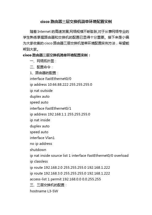
cisco路由器三层交换机简单环境配置实例随着Internet的高速发展,网络规模不断膨胀,对于从事网络专业的学生熟练掌握路由器和交换机的配置已显得十分重要。
接下来是小编为大家收集的cisco路由器三层交换机简单环境配置实例方法,希望能帮到大家。
cisco路由器三层交换机简单环境配置实例:一、网络拓扑图:二、配置命令:1、路由器的配置:interface FastEthernet0/0ip address 10.66.88.222 255.255.255.0ip nat outsideduplex autospeed autointerface FastEthernet0/1ip address 192.168.1.1 255.255.255.0ip nat insideduplex autospeed autointerface Vlan1no ip addressshutdownip nat inside source list 1 interface FastEthernet0/0 overload ip classlessip route 192.168.2.0 255.255.255.0 192.168.1.222ip route 192.168.3.0 255.255.255.0 192.168.1.222access-list 1 permit 192.168.0.0 0.0.255.255三、三层交换机的配置:hostname L3-SWip dhcp pool vlan2poolnetwork 192.168.3.0 255.255.255.0 default-router 192.168.3.1dns-server 202.101.172.35ip dhcp pool vlan1poolnetwork 192.168.2.0 255.255.255.0 default-router 192.168.2.1dns-server 202.101.172.35interface FastEthernet0/1no switchportip address 192.168.1.222 255.255.255.0 duplex autospeed autointerface FastEthernet0/2 switchport mode trunkinterface FastEthernet0/5 switchport mode trunkinterface Vlan1ip address 192.168.2.1 255.255.255.0 interface Vlan2ip address 192.168.3.1 255.255.255.0 ip classlessip route 0.0.0.0 0.0.0.0 192.168.1.1四、二层交换机的配置:1、switch0的配置:hostname sw0interface FastEthernet0/1 switchport mode trunkinterface FastEthernet0/2 switchport mode access2、switch1的配置:hostname sw1interface FastEthernet0/1switchport mode trunkinterface FastEthernet0/2switchport access vlan 2switchport mode access看了“cisco路由器三层交换机简单环境配置实例”还想看:1.思科交换机基本配置实例讲解2.三层交换机配置的实例教程3.cisco路由器怎么在虚拟环境下配置三层交换4.cisco2960交换机的简单配置5.交换机配置基础及实例讲解6.思科三层交换机与路由器的比较方法7.思科交换机配置教程详解。
交换机、路由器综合实验(三)
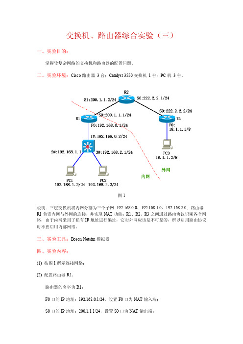
交换机、路由器综合实验(三)一、实验目的:掌握较复杂网络的交换机和路由器的配置问题。
二、实验环境:Cisco路由器3台;Catalyst 3550交换机1台;PC机3台。
图1说明:三层交换机将内网分割为三个子网192.168.0.0、192.168.1.0、192.168.2.0;路由器R1负责内网与外网的连接,并实现NAT功能;R1、R2、R3之间通过路由协议识别各个网络,由于内网采用了私有IP地址进行编址,它对外网应该是不可见的,所以启用路由协议时不要启用内部网络。
三、实验工具:Boson Netsim模拟器四、实验内容:(1) 按图1所示连接网络;(2) 配置路由器R1:路由器的名字为R1;F0口的IP地址:192.168.0.1/24,设置F0口为NAT输入端;S0口的IP地址:200.1.1.1/24,设置S0口为NAT输出端;配置NAT池,地址范围为200.1.1.10~200.1.1.20,将内网中格式为192.168.*.* 的IP 地址转换为NAT池中的IP地址;配置静态路由,将目的网络为192.168.1.0 或192.168.2.0 的数据报发往192.168.0.2;配置OSPF路由协议,区域号为10,在它的外网地址上启用协议。
(3) 配置路由器R2:路由器的名字为R2;S0口的IP地址:222.2.2.1/24;S1口的IP地址:200.1.1.2/24;配置OSPF路由协议,区域号为10,在它的所有直连网络上启用协议。
(4) 配置路由器R3:路由器的名字为R3;F0口的IP地址:18.1.1.1/8;S0口的IP地址:222.2.2.2/24;配置OSPF路由协议,区域号为10,在它的所有直连网络上启用协议。
(5) 配置三层交换机:把F0/1口设置为三层路由口,IP地址为192.168.0.2/24;把F0/2口设置为三层路由口,IP地址为192.168.1.1/24;把F0/3口设置为三层路由口,IP地址为192.168.2.1/24;配置默认路由,方向为R1路由器的F0口;启用路由功能。
Cisco3560三层交换机VLAN的配置案例
3、网络拓扑图
4、配置三层交换机 本例以思科三层交换机为例,具体配置命令如下所示:
1)、创建5个vlan 3560(config)#vlan 10 3560(config-vlan)#vlan 20 3560(config-vlan)#vlan 30 3560(config-vlan)#vlan 40 3560(config-vlan)#vlan 50 3560(config-vlan)#exit
2、各机房IP地址分配
机房一、二: IP:192.168.7.X/24,网关:192.168.7.254 机房三、四: IP:192.168.8.X/24,网关:192.168.8.254 机房五、六: IP:192.168.10.X/24,网关:192.168.10.254 机房七: IP:192.168.11.X/24,网关:192.168.11.254 服务器: IP:192.168.12.X/24 网关:192.168.12.254
2)、将端口划分到相应的VLAN
3560(config)#int range f0/1-5 3560(config-if-range)#switchport mode access 3560(config-if-range)#switchport access vlan10 3560(config-if-range)#exit 3560(config)#int range f0/6-10 3560(config-if-range)#switchport mode access 3560(config-if-range)#switchport access vlan20 3560(config-if-range)#exit 3560(config)#int range f0/11-15 3560(config-if-range)#switchport mode access 3560(config-if-range)#switchport access vlan30 3560(config-if-range)#exit 3560(config)#int range f0/16-20
思科三层交换机配置总结
思科三层交换机配置总结思科交换机的基本配置命令学习CISCO交换机基本配置:Console端口连接用户模式hostname# ;特权模式hostname(config)# ;全局配置模式hostname(config-if)# ;交换机口令设置:switch>enable ;进入特权模式switch#config terminal ;进入全局配置模式switch(config)#hostname csico ;设置交换机的主机名switch(config)#enable secret csico1 ;设置特权加密口令switch(config)#enable password csico8 ;设置特权非密口令switch(config)#line console 0 ;进入控制台口switch(config-line)#line vty 0 4 ;进入虚拟终端switch(config-line)#login ;虚拟终端允许登录switch(config-line)#password csico6 ;设置虚拟终端登录口令csico6switch#exit ;返回命令交换机VLAN创建,删除,端口属性的设置,配置trunk端口,将某端口加入vlan中,配置VTP:switch#vlan database ;进入VLAN设置switch(vlan)#vlan 2 ;建VLAN 2switch(vlan)#vlan 3 name vlan3 ;建VLAN 3并命名为vlan3 switch(vlan)#no vlan 2 ;删vlan 2switch(config)#int f0/1 ;进入端口1switch(config)#speed ? 查看speed命令的子命令switch(config)#speed 100 设置该端口速率为100mb/s (10/auto)switch(config)#duplex ? 查看duplex的子命令switch(config)#duplex full 设置该端口为全双工(auto/half)switch(config)#description TO_PC1 这是该端口描述为TO_PC1 switch(config-if)#switchport access vlan 2 ;当前端口加入vlan 2switch(config-if)#switchport mode trunk ;设置为trunk模式(access模式)switch(config-if)#switchport trunk allowed vlan 1,2 ;设置允许的vlanswitch(config-if)#switchport trunk encap dot1q ;设置vlan 中继switch(config)#vtp domain vtpserver ;设置vtp域名相同switch(config)#vtp password ;设置发vtp密码switch(config)#vtp server ;设置vtp服务器模式switch(config)#vtp client ;设置vtp客户机模式交换机设置IP地址,默认网关,域名,域名服务器,配置和查看MAC地址表:switch(config)#interface vlan 1 ;进入vlan 1switch(config-if)#ip address 192.168.1.1 255.255.255.0 ;设置IP地址switch(config)#ip default-gateway 192.168.1.6 ;设置默认网关switch(config)#ip domain-name /doc/0113809409.html, 设置域名switch(config)#ip name-server 192.168.1.18 设置域名服务器switch(config)#mac-address-table? 查看mac-address-table 的子命令switch(config)#mac-address-table aging-time 100 设置超时时间为100msswitch(config)#mac-address-table permanent 0000.0c01.bbcc f0/3 加入永久地址在f0/3端口switch(config)#mac-address-table restricted static 0000.0c02.bbcc f0/6 f0/7 加入静态地址目标端口f0/6源端口f0/7 switch(config)#endswitch#show mac-address-table 查看整个MAC地址表switch#clear mac-address-table restricted static 清除限制性静态地址交换机显示命令:switch#write ;保存配置信息switch#show vtp ;查看vtp配置信息switch#show run ;查看当前配置信息switch#show vlan ;查看vlan配置信息switch#show interface ;查看端口信息switch#show int f0/0 ;查看指定端口信息switch#show int f0/0 status;查看指定端口状态switch#dir flash: ;查看闪存Cisco路由器配置命令大全网络2010-06-26 06:43:44 阅读657 评论0 字号:大中小订阅 .(1)模式转换命令用户模式----特权模式,使用命令"enable"特权模式----全局配置模式,使用命令"config t"全局配置模式----接口模式,使用命令"interface+接口类型+接口号"全局配置模式----线控模式,使用命令"line+接口类型+接口号"注:用户模式:查看初始化的信息.特权模式:查看所有信息、调试、保存配置信息全局模式:配置所有信息、针对整个路由器或交换机的所有接口接口模式:针对某一个接口的配置线控模式:对路由器进行控制的接口配置(2)配置命令show running config 显示所有的配置show versin 显示版本号和寄存器值shut down 关闭接口no shutdown 打开接口ip add +ip地址配置IP地址secondary+IP地址为接口配置第二个IP地址show interface+接口类型+接口号查看接口管理性show controllers interface 查看接口是否有DCE电缆show history 查看历史记录show terminal 查看终端记录大小hostname+主机名配置路由器或交换机的标识config memory 修改保存在NVRAM中的启动配置exec timeout 0 0 设置控制台会话超时为0service password-encryptin 手工加密所有密码enable password +密码配置明文密码ena sec +密码配置密文密码line vty 0 4/15 进入telnet接口password +密码配置telnet密码line aux 0 进入AUX接口password +密码配置密码line con 0 进入CON接口password +密码配置密码bandwidth+数字配置带宽no ip address 删除已配置的IP地址show startup config 查看NVRAM中的配置信息copy run-config atartup config 保存信息到NVRAM write 保存信息到NVRAMerase startup-config 清除NVRAM中的配置信息show ip interface brief 查看接口的谪要信息banner motd # +信息 + # 配置路由器或交换机的描素信息description+信息配置接口听描素信息vlan database 进入VLAN数据库模式vlan +vlan号+ 名称创建VLANswitchport access vlan +vlan号为VLAN为配接口interface vlan +vlan号进入VLAN接口模式ip add +ip地址为VLAN配置管理IP地址vtp+service/tracsparent/client 配置SW的VTP工作模式vtp +domain+域名配置SW的VTP域名vtp +password +密码配置SW的密码switchport mode trunk 启用中继no vlan +vlan号删除VLANshow spamming-tree vlan +vlan号查看VLA怕生成树议2. 路由器配置命令ip route+非直连网段+子网掩码+下一跳地址配置静态/默认路由show ip route 查看路由表show protocols 显示出所有的被动路由协议和接口上哪些协议被设置show ip protocols 显示了被配置在路由器上的路由选择协议,同时给出了在路由选择协议中使用的定时器等信息router rip 激活RIP协议network +直连网段发布直连网段interface lookback 0 激活逻辑接口passive-interface +接口类型+接口号配置接口为被动模式debug ip +协议动态查看路由更新信息undebug all 关闭所有DEBUG信息router eigrp +as号激活EIGRP路由协议network +网段+子网掩码发布直连网段show ip eigrp neighbors 查看邻居表show ip eigrp topology 查看拓扑表show ip eigrp traffic 查看发送包数量router ospf +process-ID 激活OSPF协议network+直连网段+area+区域号发布直连网段show ip ospf 显示OSPF的进程号和ROUTER-IDencapsulation+封装格式更改封装格式no ip admain-lookup 关闭路由器的域名查找ip routing 在三层交换机上启用路由功能show user 查看SW的在线用户clear line +线路号清除线路3. 三层交换机配置命令配置一组二层端口configure terminal 进入配置状态nterface range {port-range} 进入组配置状态配置三层端口configure terminal 进入配置状态interface {{fastethernet | gigabitethernet} interface-id} | {vlan vlan-id} | {port-channel port-channel-number} 进入端口配置状态no switchport 把物理端口变成三层口ip address ip_address subnet_mask 配置IP地址和掩码no shutdown 激活端口例:Switch(config)# interface gigabitethernet0/2Switch(config-if)# no switchportSwitch(config-if)# ip address 192.20.135.21 255.255.255.0Switch(config-if)# no shutdown配置VLANconfigure terminal 进入配置状态vlan vlan-id 输入一个VLAN号, 然后进入vlan配态,可以输入一个新的VLAN号或旧的来进行修改。
Cisco 三层交换
第16章
Page 1/11
单臂路由实现VLAN之间通信
VLAN之间的通信需要路由器来完成
Router(config)#interface fastEthernet 0/0 Router(config-if)#no shutdown Router(config-if)#exit f0/0 Router(config)#interface fastEthernet 0/0.1 Router(config-subif)#encapsulation dot1q 1 Router(config-subif)#ip address 10.1.1.1 255.0.0.0 Router(config-subif)#exit VLAN 1
f0/16-23
192.168.3.156 Vlan 3
SW-2L
f0/11-15 192.168.2.156 Vlan 2 192.168.2.0/24
192.168.3.0/24
Page 5/11
三层交换机实现VLAN互通实例9-2
在2层交换机上配置VLAN
SW-2L(config)#vlan 2 SW-2L(config-vlan)#vlan 3 SW-2L(config-vlan)#exit SW-2L(config)#interface range f0/11 - 15 SW-2L(config-if-range)#switchport access vlan 2 SW-2L(config-if-range)#switchport mode access SW-2L(config)#interface range f0/16 - 23 SW-2L(config-if-range)#switchport access vlan 3 SW-2L(config-if-range)#switchport mode aN的IP地址
Cisco 3560 系列简单三层划分 配置
Cisco 3560 系列简单三层划分配置三层交换机具备网络层的功能,实现VLAN 相互访问的原理是:利用三层交换机的路由功能,通过识别数据包的IP地址,查找路由表进行选路转发,三层交换机利用直连路由可以实现不同VLAN 之间的相互访问。
三层交换机给接口配置IP 地址。
采用SVI(交换虚拟接口)的方式实现VLAN 间互连。
SVI是指为交换机中的VLAN 创建虚拟接口,并且配置IP地址。
实现目标:PC3能访问PC1和PC2, 但PC1不能和PC2/PC3互通 PC2不能和PC1/PC3互通。
\一、首先我们配置PC上的IP和GateWay:PC1IP: 192.168.1.2Submark: 255.255.255.0Gateway: 192.168.1.1PC2IP: 192.168.2.2Submark: 255.255.255.0Gateway: 192.168.2.1PC3IP: 192.168.1.3Submark: 255.255.255.0Gateway: 192.168.1.1二、其次进行对Cisco2950进行vlan划分:Switch1:Switch>en --进入特权Switch#conf t --全局配置Enter configuration commands, one per line. End with CNTL/Z.Switch(config)#vlan 2 --创建vlan 2 使用默认vlan名Switch(config-vlan)#exit --退出vlan 2 配置操作Switch(config)#vlan 3 --创建vlan 3Switch(config-vlan)#exit -- 退出vlan 3 配置操作Switch(config)#int fa0/2 --配置交换机2口Switch(config-if)#switch access vlan 2 设置交换机2口为vlan 2 Switch(config-if)#exit --退出2口操作Switch(config)#int fa0/3 --配置3口Switch(config-if)#switch acces vlan 3 --设置交换机3口为 vlan 3 Switch(config-if)#exit --退出3口配置操作。
- 1、下载文档前请自行甄别文档内容的完整性,平台不提供额外的编辑、内容补充、找答案等附加服务。
- 2、"仅部分预览"的文档,不可在线预览部分如存在完整性等问题,可反馈申请退款(可完整预览的文档不适用该条件!)。
- 3、如文档侵犯您的权益,请联系客服反馈,我们会尽快为您处理(人工客服工作时间:9:00-18:30)。
配置cisco交换机三层交换的综合范例所有服务器划分为一个VLAN,即VLAN 50。
四台Catalyst 2950G-24-SMI交换机也只划分为一个VLAN,分别为VLAN 60、VLAN 70、VLAN 80和VLAN 90。
Catalyst 3550-24-EMI划分为4个VLAN,分别为VLAN 10、VLAN 20、VLAN 30和VLAN 40。
Catalyst 3550-24-SMI划分2个VLAN,分别为VLAN 60和VLAN 80,与另外两台Catalyst 2950G-24-SMI交换机分别位于同一VLAN。
实例分析由于所有Catalyst 2950G交换机都是一个独立的VLAN,因此,必须先在这些交换机上创建VLAN(VLAN 60~VLAN 90),并将所有端口都指定至该VLAN。
然后,再在Catalyst 4006交换机相应端口上分别创建VLAN。
Catalyst 4006的1000Base-X端口分别与各Catalyst 2950G的1000Base-X端口连接。
其中,GigabitEthernet3/2端口连接至1号Catalyst 2950交换机(VLAN 60),GigabitEthernet3/3端口连接至2号Catalyst 2950交换机(VLAN 70),GigabitEthernet3/4端口连接至3号Catalyst 2950交换机(VLAN 80),GigabitEthernet3/5端口连接至4号Catalyst 2950交换机(VLAN 90),GigabitEthernet3/6端口连接至6号楼交换机(VLAN 80)。
由于在Catalyst 3550-24-EMI上划分有4个VLAN(VLAN 10~VLAN 40),而4个VLAN 都需借助于一条1000Base-X链路实现与Catalyst 4006的GigabitEthernet3/1端口连接,因此,必须在Catalyst 4006与Catalyst 3550-24- EMI之间创建一个Trunk。
同样,在Catalyst 3550-24-SMI上划分有2个VLAN(VLAN 60和VLAN 80),而4个VLAN 都需借助于一条1000Base-X链路实现与Catalyst 4006的GigabitEthernet3/6端口连接,因此,必须在Catalyst 4006与Catalyst 3550-24- EMI之间创建一个Trunk。
另外,所有服务器均连接至Catalyst 4006的1000Base-T模块,并单独成为一个VLAN(VLAN 90),因此,也必须为这些交换机创建一个VLAN,并将所有端口指定至该VLAN。
需要注意的是,考虑到网络管理的需要,也可以剩余几个RJ-45端口(如21至24端口)不指定至任何VLAN,从而便于连接网络管理设备。
默认状态下,所有端口都属于VLAN1,而且也只有在VLAN1中才能实现对网络中所有设备的管理。
配置清单●Cisco Catalyst 4006交换机配置清单Current configuration : 5594 bytes!version 12.1no service padservice timestamps debug uptimeservice timestamps log uptimeno service password-encryptionservice compress-config!hostname hsnc!boot system bootflash:cat4000-is-mz.121-8a.EW1.binno logging consoleenable secret level 1 5 $1$rkQW$1HKyKdN5f.Ri5zxeoF8Yv/!ip subnet-zero!!!interface GigabitEthernet1/1no snmp trap link-status!--不为Supervisor Engine III G引擎中的1000Base-X插槽指定VLAN interface GigabitEthernet1/2no snmp trap link-status!!interface GigabitEthernet2/1switchport access vlan 50no snmp trap link-status!--将端口GigabitEthernet2/1指定至VLAN 50!interface GigabitEthernet2/2switchport access vlan 50no snmp trap link-status!interface GigabitEthernet2/3switchport access vlan 50no snmp trap link-status!interface GigabitEthernet2/4switchport access vlan 50no snmp trap link-status!switchport access vlan 50no snmp trap link-status!interface GigabitEthernet2/6 switchport access vlan 50no snmp trap link-status!interface GigabitEthernet2/7 switchport access vlan 50no snmp trap link-status!interface GigabitEthernet2/8 switchport access vlan 50no snmp trap link-status!interface GigabitEthernet2/9 switchport access vlan 50no snmp trap link-status!interface GigabitEthernet2/10 switchport access vlan 50no snmp trap link-status!interface GigabitEthernet2/11 switchport access vlan 50no snmp trap link-status!interface GigabitEthernet2/12 switchport access vlan 50no snmp trap link-status!interface GigabitEthernet2/13 switchport access vlan 50no snmp trap link-status!interface GigabitEthernet2/14 switchport access vlan 50no snmp trap link-status!interface GigabitEthernet2/15 switchport access vlan 50no snmp trap link-status!switchport access vlan 50no snmp trap link-status!interface GigabitEthernet2/17switchport access vlan 50no snmp trap link-status!interface GigabitEthernet2/18switchport access vlan 50no snmp trap link-status!interface GigabitEthernet2/19switchport access vlan 50no snmp trap link-status!interface GigabitEthernet2/20switchport access vlan 50no snmp trap link-status!--不将GigabitEthernet2/20~24指定至任何VLAN!interface GigabitEthernet3/1switchport trunk encapsulation dot1q!--启用802.1Q Trunk封装协议,即在该端口创建Trunk switchport trunk allowed vlan 1-80!--允许vlan 1-90在该中继线通讯!--可以拒绝或允许某个VLAN访问该Trunk!--确保未被授权的VLAN通过该Trunk,实现VLAN的访问安全 switchport mode trunk !--将该端口设置为Trunkdescription netcenterno snmp trap link-status!interface GigabitEthernet3/2switchport access vlan 60no snmp trap link-status!--将端口GigabitEthernet3/2指定至VLAN 60!interface GigabitEthernet3/3switchport access vlan 70no snmp trap link-status!--将端口GigabitEthernet3/3指定至VLAN 70!interface GigabitEthernet3/4switchport access vlan 80no snmp trap link-status!--将端口GigabitEthernet3/4指定至VLAN 80!interface GigabitEthernet3/5switchport access vlan 90no snmp trap link-status!--将端口GigabitEthernet3/5指定至VLAN 90!interface GigabitEthernet3/6switchport trunk encapsulation dot1q!--启用802.1Q Trunk封装协议,即在该端口创建Trunk switchport trunk allowed vlan 1-80!--允许vlan 1-90在该中继线通讯!--可以拒绝或允许某个VLAN访问该Trunk!--从而确保未被授权的VLAN通过该Trunk,实现VLAN访问安全switchport mode trunk!--将该端口设置为Trunkdescription netcenterno snmp trap link-status!interface Vlan1description netmangerno ip address!!--对VLAN1进行描述interface Vlan10description network centerno ip address!--对VLAN2进行描述!interface Vlan20description computer centerno ip address!interface Vlan30description network labno ip address!interface Vlan40description huaxuelouno ip address!interface Vlan50description wulilouno ip address!interface Vlan60description shengwulouno ip address!interface Vlan70description zhongwenxino ip address!interface Vlan80description tushuguanno ip address!!line con 0stopbits 1line vty 0 4password aaalogin!end●Cisco Cata lyst 3550-EMI配置清单Building configuration...Current configuration : 4055 bytes!version 12.1no service padservice timestamps debug uptimeservice timestamps log uptimeno service password-encryption!hostname office!enable secret 5 $1$p0fU$JeyPOM0RuL.Fqfe71efHF1 !ip subnet-zero!!spanning-tree extend system-id!!!interface FastEthernet0/1switchport access vlan 10!--将端口FastEthernet0/1指定至VLAN 10 no ip address!interface FastEthernet0/2switchport access vlan 10no ip address!interface FastEthernet0/3switchport access vlan 10no ip address!interface FastEthernet0/4switchport access vlan 10no ip address!interface FastEthernet0/5switchport access vlan 10no ip address!interface FastEthernet0/6switchport access vlan 20no ip address!--将端口FastEthernet0/6指定至VLAN 20 !interface FastEthernet0/7switchport access vlan 20no ip address!interface FastEthernet0/8switchport access vlan 20no ip address!interface FastEthernet0/9switchport access vlan 20no ip address!interface FastEthernet0/10switchport access vlan 20no ip address!interface FastEthernet0/11switchport access vlan 30no ip address!--将端口FastEthernet0/6指定至VLAN 30 !interface FastEthernet0/12switchport access vlan 30no ip address!interface FastEthernet0/13switchport access vlan 30no ip address!interface FastEthernet0/14switchport access vlan 30no ip address!interface FastEthernet0/15switchport access vlan 30no ip address!interface FastEthernet0/16switchport access vlan 30no ip address!interface FastEthernet0/17switchport access vlan 30no ip address!interface FastEthernet0/18switchport access vlan 30no ip address!interface FastEthernet0/19switchport access vlan 40no ip address!--将端口FastEthernet0/6指定至VLAN 40 !interface FastEthernet0/20switchport access vlan 40no ip address!interface FastEthernet0/21switchport access vlan 40no ip address!interface FastEthernet0/22switchport access vlan 30no ip address!interface FastEthernet0/23switchport access vlan 40no ip address!interface FastEthernet0/24switchport access vlan 40no ip address!interface GigabitEthernet0/1switchport trunk encapsulation dot1q!--启用802.1Q Trunk封装协议,即在该端口创建Trunk switchport trunk allowed vlan 1-80!--允许vlan 1-80在该中继线通讯switchport mode trunk!--将该端口设置为Trunkno ip address!interface GigabitEthernet0/2no ip address!interface Vlan1ip address 172.16.100.12 255.255.255.0!--LAN1指定IP地址no ip route-cacheno ip mroute-cache!ip classlessip http server!!!!line con 0line vty 0 4password aaaloginline vty 5 15login!end●Cisco Catalyst 3550-SMI配置清单Building configuration...Current configuration : 4055 bytes!version 12.1no service padservice timestamps debug uptimeservice timestamps log uptimeno service password-encryption!hostname office!enable secret 5 $1$p0fU$JeyPOM0RuL.Fqfe71efHF1 !ip subnet-zero!!spanning-tree extend system-id!!!interface FastEthernet0/1switchport access vlan 60!--将端口FastEthernet0/1指定至VLAN 60no ip address!interface FastEthernet0/2switchport access vlan 60no ip address!interface FastEthernet0/3switchport access vlan 60no ip address!interface FastEthernet0/4switchport access vlan 60no ip address!interface FastEthernet0/5switchport access vlan 60no ip address!interface FastEthernet0/6switchport access vlan 20no ip address!--将端口FastEthernet0/6指定至VLAN 20 !interface FastEthernet0/7switchport access vlan 20no ip address!interface FastEthernet0/8switchport access vlan 20no ip address!interface FastEthernet0/9switchport access vlan 20no ip address!interface FastEthernet0/10switchport access vlan 20no ip address!interface FastEthernet0/11switchport access vlan 80no ip address!--将端口FastEthernet0/6指定至VLAN 80 !interface FastEthernet0/12switchport access vlan 80no ip address!interface FastEthernet0/13switchport access vlan 80no ip address!interface FastEthernet0/14switchport access vlan 80no ip address!interface FastEthernet0/15switchport access vlan 80no ip address!interface FastEthernet0/16switchport access vlan 80no ip address!interface FastEthernet0/17switchport access vlan 80no ip address!interface FastEthernet0/18switchport access vlan 80no ip address!interface FastEthernet0/19switchport access vlan 80no ip address!--将端口FastEthernet0/6指定至VLAN 80!interface FastEthernet0/20switchport access vlan 80no ip address!interface FastEthernet0/21switchport access vlan 80no ip address!interface FastEthernet0/22switchport access vlan 80no ip address!interface FastEthernet0/23switchport access vlan 80no ip address!interface FastEthernet0/24switchport access vlan 80no ip address!interface GigabitEthernet0/1switchport trunk encapsulation dot1q!--启用802.1Q Trunk封装协议,即在该端口创建Trunk switchport trunk allowed vlan 1-80!--允许vlan 1-80在该中继线通讯switchport mode trunk!--从将该端口设置为Trunkno ip address!interface GigabitEthernet0/2no ip address!interface Vlan1ip address 172.16.100.13 255.255.255.0!--为LAN1指定IP地址no ip route-cacheno ip mroute-cache!ip classlessip http server!!!!line con 0line vty 0 4password aaaloginline vty 5 15login!end●Cisco Catalyst 2950G配置清单四台Cisco Catalyst 2950G的配置基本相同,下面仅列出VLAN 60的配置情况。