ASHLY 24.24M使用手册
扩声个性化设计的实质就是以人为本的扩声清晰度之设计

扩声个性化设计的实质就是以人为本的扩声清晰度之设计——兼述北京师范大学体育馆扩声工程个性化设计2010-6-1 祝科(总工)一、概述扩声工程个性化设计实质就是以人为本,以最佳效果为目的的两方面设计1. 针对各个不同声场环境的扩声清晰度设计2. 服务于扩声清晰度的功能与管理控制设计目前的问题是:业主投入各种项目的扩声资金不断提高,扩声清晰度却一直不高,但却能通过验收!原因之一:工程验收的五项扩声指标里,目前暂时没有规定可测量的清晰度STTPA指标,因此满足扩声五项指标要求后还听不清也只能验收!原因是扩声五项指标是为清晰度服务的必要条件,但它们不是实现扩声清晰度的充分条件(要达到多种语言可懂度,清晰度STTPA指标要大于0.50 STI以上)原因之二:投入巨大资金做建声处理后的大型场馆,混响时间很难达标。
其原因很复杂………实际的混响时间往往比设计的偏长,这种环境下选择常规音箱、多声源布局扩声方式,语言清晰度很难达标。
围绕体育场馆的扩声清晰度设计主要有三个部分。
首先:语言清晰度的设计是第一位的,如何配置扩声系统设备来实现语言清晰度;如何实现音乐丰满度及多种功能的实现。
其次:是扩声系统五项技术指标如何设计,实质上也是语言清晰度的设计,只是必要条件而已。
语言清晰度的设计,并结合该项目招标要求的五项扩声技术指标的设计,这才是扩声清晰度的充分必要条件。
尤其是奥运会体育场馆提出语言可懂度STIPA>0.50的技术指标,使其扩声系统设计指标更加完善。
最后:是声学EASE软件仿真模型设计,是在工程设计阶段,就可预测体育场馆竣工后的语言清晰度(语言辅音清晰度损失率的百分比)。
笔者例举北京师范大学体育馆之扩声工程个性化设计,就是依照上述之三个部分,按顺序进行设计的。
本体育馆是北京奥运会的美国国家队各项目参赛队的专用综合热身馆,也是备受关注的最著名的梦之队——美国国家篮球队热身的地方。
美国方面要求语言扩声能让队员们“很轻松的听清楚”,竟然要求达到扩声语言清晰度STIPA>0.70(超过普通小型会议室的扩声语言清晰度要求)国内对于扩声清晰度方面的实践经验与研究相对落后和缺乏,不太适应这种非常高的清晰度要求. 截至目前,国内还没有哪个体育场馆的扩声语言清晰度有如此之高的要求!美国人测试认为:200Hz-4KHz间(1/3倍频程)对语言清晰度贡献之和为91.5%中国人测试认为:200Hz-4KHz间(1/3倍频段)对语言清晰度贡献之和为93.8%美国声学专家唐•戴维斯说:“提供平滑的频响比扩展频响更重要!由增加频带宽度所引起的听觉感受,弱于不平坦的频响所带来的差别感受,对此很少有人能理解”。
ASHLY软件控制说明书

此版本目前只做内部参考用(最终细节均以ASHLY 英文原版参考手册为准翻译/编写:ONLY.CHENG Protea System Software 软件控制说明(ASHLY Protea 4.24C)硬件名称:ASHLY Protea 4.24C软件名称:Protea System Software软件版本:5.0语言环境:英语系统平台:WIN95/98/2000/NT简单介绍:ASHLY Protea 4.24C是ASHLY 公司出品的数字式分频器/系统处理器,具有4 个输入,8个输出;占用1U机架空间;可以任意分配输入至输出;具有分频、均衡、延时和限幅等功能;具有LINKWITZ-RILEY、BESSEL和BUTTERWORTH 滤波器;滤波器斜率分别为12、18、24、48dB/倍频程;参数式均衡器;带通、1/64 至4 倍频程范围;输入和输出延时;每一输出均具有限幅器;直观的用户界面;通过PC 或MIDI 进行控制;AMX 兼容网络链接控制;专门的输入和输出电平表;平衡式输入和输出;XLR 信号连结器;双重安全保护设置;使用简单方便,设定好之后,甚至无需人工操控,简洁精致的电路设计,保证了它能够实现无忧、高性能的工作。
与其它同类产品相比较,它的体积小巧,重量更轻,音质细腻,PC 控制软件使用方便,操作灵活,高级的音质和效果,大众化的价钱,正是这些特点,使它适用于专业录音棚、电台、舞台上、剧院里、餐馆、俱乐部、酒吧、旅馆、商场、健身室、保龄球场以至户外的游乐场、火车站、体育场馆等……甚至音乐家的家里……所以它能够广泛的用在固定安装和现场扩声系统中,受到了众多专家和用户的一致好评,本说明主要介绍怎样通过软件对ASHLY Protea 4.24C进行设定,是您对ASHLY Protea 4.24C以及它的PC控制软件Protea System Software有一个基本的了解。
ASHLY Protea 4.24C 技术特性:输入:有源平衡式,18KΩ阻抗最大输入电平:+20dBu输出:有源平衡式,100Ω阻抗最大输出电平:+20dBu频率响应:±2.5dB,20Hz-20kHz总谐波失真:<0.01%@1kHz, +20dBu动态范围:>110dB(20-20kHz),不计权输出噪声:<-90dBu, 不计权EQ 滤波器:数量:6 个/输入,4 个/输出参数式带宽:1/64 至4 倍频程范围:+15/-30dB,0.1dB步进值频率间隔:1/24 倍频程高通滤波器斜率:6 或12dB/备频程可选此版本目前只做内部参考用(最终细节均以ASHLY 英文原版参考手册为准翻译/编写:ONLY.CHENG频率范围:19.7Hz-20kHz范围:+15,0.1dB步进值低通滤波器斜率:6 或12dB/备频程可选频率范围:3.1886kHz-20.1587kHz范围:+15,0.1dB步进值分频滤波器高通滤波器类型:linkwitz-riley,Bessel,butterworth斜率:12/18/24/48 倍频程频率范围:0-21.9833kHz,245 步进值低通滤波器类型:linkwitz-riley,Bessel,butterworth斜率:12/18/24 倍频程频率范围:0-21.9833kHz,245 步进值延时输入最大延时:682.5ms输出最大延时:21.33ms步进值:20μs输入和输出增益范围:+12/-40dB,0.1dB步进值极性:0゜或180゜压缩器/限幅器门阈:-20dBu-20dBu 1dB步进值压缩比:1.2:1-∞(1.2,1.5,2,3,4,6,10,20, ∞:1)上冲时间:0.5ms-50ms/dB释放时间:10ms-1s/dB范围:20Hz-10.6kHz处理器输入模/数转换:24bit输出数/模转换:24bit处理器:24bit,56bit存储器采样率:48kHz信号延时:1.46ms其它电源要求:80-260VAC,30W包装重量:10 磅尺寸:19”x1.75”x6.0”(宽x 高x 深)输入输出连接器:XLR环境温度:40-120゜F控制方式protea system software(windows tm95、98、2000 和NT平台)、MIDI或SIA-Smaart软件进行编程和控制。
Ashly FX系列DSP功能强大的音频放大器说明书
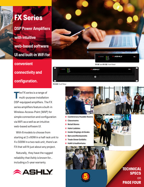
FX 500 Front PanelFX 60 and FX 125 Front PanelThe FX series is a range of multi-purpose installationDSP-equipped amplifiers. The FX series amplifiers feature a built-in Wireless-Access-Point (WAP) for simple connection and configuration via WiFi as a well as an intuitive web-based software UI. With 6 models to choose from starting at 2 x 60W in a half rack unit to 4 x 500W in a two rack unit, there’s an FX that will fit just about any project.Naturally, they have the rugged reliability that Ashly is known for…including a 5-year warranty.TECHNICALSPECSonPAGE FOURFX SeriesDSP Power A mplifiers with intuitive web-based software UI and built-in WiFi for convenient connectivity and configuration.❚Conference/Huddle Rooms ❚Classrooms ❚Retail Stores ❚Hotel Lobbies❚Inside Displays & Kiosks ❚Bars and Restaurants ❚Trade Show Exhibits ❚HoW & AuditoriumsFX 60 and FX 125 Front PanelFX 500 Front PanelFX 500.2 – Back FX 500.4 – Back – Amplifier operational.– Standby Mode.– GPIO triggered Standby Mode– No input signal present.– Signal present on one or more inputs.– Signal limiting/clipping on one or more inputs.Off – No output signal present.Green – Signal present on one or more outputs.Amber – Signal limiting/clipping on one or more outputs.Red – One or more channel pair is in overload/protection mode.4-Channel Models– WiFi disabled. – WiFi enabled– No Ethernet network detected. – Network enabled– Ethernet network detected.AnalogAnalog AC receptacle100-240VAC 50/60HzInput/Output 2-Channel ModelsEach FX model offers a healthy compliment of IO (include Digital SPDIF In & Out) and programmable integration ports for remote Volume Control, GP triggers and more.FX is networkable via Ethernet for wired LAN connection, or via its built-in WiFi hotspot. FX allows system configurations that don’t require additional equipment, such as stand-alone DSP or speaker system processors. All of that is in one box.Page 3 of 4FX SeriesHigh-Density DSP Power AmplifiersIntelligent DSPTo control FX’s powerful DSP, you’ll find easy access to its intuitive and user-friendly interface via a simple web browser (similar to AquaControl). No software to install (it’s built into the FX unit).Just connect using the Ethernet port or built-in WiFi and you’re ready to Rock & Roll. The WiFi connection allows secure ID and password protection from unauthorized use and for more advanced users, Ethernet allows custom IP settings for use on a more complex wired LAN.The FX Series features a powerful DSP engine that canconfigure to suit virtually any task, without the need for additional equipment. From processing input sources, routing and output DSP that can fine tune the sound of any speaker. Everything you need is right there. These will mixinto Zones A-D and then into Outputs (2 or 4 depending on the number of amplifier channels). All models have a 4-channel DSP configuration with Input processing, Zone Processing, Output Processing, Speaker Processing and Device SettingsAnalog 3Analog 2Analog 1Analog 4SPDIF (stereo)Input Setupgn i t u o R & p u t e S e n o Z Output SetupOutput 1Output 2Output 3Output 4sr e t e m a r a P t n e m t s u j d A m o o R sr e t e m a r a P t n e m t s u j d A r e k a e p S Four-Channel models onlyIntuitive Software UIBrowser-based control from any deviceFA1.2RPM – 1 or 2-amp rack-mount kitFA2.2RPM – Rear rack support kitAshly Audio, Inc. • 847 Holt Road • Webster, NYUSA • US toll-free +1.585.872.0010 Fax +1.585.872.0739•***************©2019-2022 Ashly Audio A Division of JAM Industries USA, LLC. All Rights Reserved. Ashly is a registered trademark. Any other trademarks are property of their respective holders.All Specifications are subject to change.FX_DS_v01.1FX SERIES ARCHITECT & ENGINEERING SPECIFICATIONSin .txt format are available in the DOWNLOADS section of FX SERIES2D AUTOCAD FILES are available in the DOWNLOADS section of https://bit.ly/3ppPEvUDownload the full FX User Manual at https://bit.ly/3GL73FdUSER MANUALOptional Rack Mounts (For half rack models)1) N ote:*100V line mode operates @ -1 dB (≈ 90 V)**FX125.4 and FX 500.4 may only Powershare across Ch1/2 and Ch3/4 Country Of Origin (COO): FX60.x and 125.x is China and FX 500.x is Thailand。
Ashly nX Power Amplifiers产品介绍说明书

Ashly’s new line of nX Power Amplifiers feature lightweight, energy-efficient Class-D switching amplifier technology combined with a switch mode power supply. nX amplifiers are available in three product families (nX, nXe, nXp) and are designed to meet the most demanding live sound and fixed installation sound systems in stadiums, arenas, performance venues, worship spaces and convention centers.nXp Series features Protea™ DSP and is available in either 2 or 4-channel models. Use rear panel DIP switches to program each channel output for either High-Z (70V or 100V Constant Voltage) or Low-Z (stable down to 2 Ohms) operation. When in sleep mode, the nX amplifiers draw less than 1 Watt.nXp is networkable with Ethernet control. It also has serial data control, aux preamp outputs, instant standby mode, preset recall, fault condition logic outputs, and optional network audio and digital audio capability all controlled using our Protea™ Software Suite. nXp amplifiers add 32-bit SHARC DSP processing (with 48kHz & 96kHz sampling) as standard equipment for comprehensive audio processing, with built-in signal generator or test tone and noise-masking. Swept load impedance monitoring is available on each amplifier channel output.nXp Series Features:• 2 and 4-channel high-output, lightweight amplifiers with programmable output on each channel (High-Z or Low-Z, selected via rear panel DIP switches)• P ower-saving, Energy Management System ‡ (Ashly EMS™) automatic <1W sleep-mode (defeatable)• F ront panel power switch and level controls (can be disabled for security)• R ear panel DIP switches per channel for selection of high pass filter, limiter, input gain, and High-Z or Low-Z speaker output configuration• R emote DC level control on each input channel• S witch mode power supply automatically detects 120V or 240V AC operation • E xtensive protection circuitry, continuously variable cooling fans• M ultiple independent internal power sup -plies provide increased channel separation and reliability• E thernet port for use with control and monitoring of amplifier functions, with front panel COM activity LED • S erial data port for use with Ashly remote control devices, or optional RS-232 con -verter for third party controllers (INA-1)• U se Protea™ Software to remotely disable all front panel controls, including the on/off switch, for a tamper-proof installationNXP3.04NXP3.02NXP1.54NXP1.52NXP8004NXP8002NXP4004NXP4002NXP SERIESP ower A mPlifiers w / P rogrAmmAble o utPuts A nd P roteA ™70V Rated 100V Rated5-Year WarrantyAshly EMS™Hand-built in Webster, NY* Measurements based on CEA-2006/490A, 20mS 1kHz 1% THD+N, 480mS 1kHz -20dB.‡ <1W sleep mode can be defeated for applications that are subject to third-party performance standards that prohibit a sleep mode, including those used for Mass Notification and Emergency Communication Systems and those subject to ANSI/UL 2572. Note: When making a true comparison of energy efficiency, one must look at the Thermal Dissipation (BTU/hr) numbers for a product. All other efficiency, i.e. "percentage" numbers are not standards based, and therefore may be marketing hype. Ashly Audio builds highly efficient Class-D amplification with SMPS that will equal or surpass the competition on BTU/hr thermal output (unused energy given off as heat). Please check our published BTU/hr specifications for more information.SelectableComponentsAdditional Features:• R eal-Time Clock with Event Scheduler• I nstant Standby Mode, 30% reduction in power consumption with on/off triggered by contact closure, software control, or event scheduler • P rogrammable power-on delay• P reset recall via contact closure, software control, remote control, or event scheduler• A ux preamp outputs, and fault condition logic outputs • O ptional Cobranet® or Dante® network audio and AES3 digital audio input with pass-through• D ynamics, gain, equalization, FIR filter ready, 2x4 or 4x4 matrix mixer, crossover, delay, metering, and signal generator functions for test and noise masking applications• P recision swept load impedance monitoring of each amplifier channel for quick and easy diagnosis of sound system problems remotely via Ethernet• N eutrik® Combo XLR – 1/4” TRS jack plus Euroblock input connectors• N eutrik® speakON® twist locking loudspeaker connectors for security, safety, and reliability• Neutrik® powerCON® detachable AC mains connectornXp 3.04 Rear Panel ConfigurationAshly Audio, Inc.847 Holt RoadWebster, NY 14580 USA +1-800-828-6308 US toll free +1-585-872-0010 tel +1-585-872-0739 fax **************u ***************u u©2013 All features, specifications and graphical representations are subject to change or improvement without notice and may not represent the final product.Ashly Audio is a division of Jam Industries, Ltd. DS-1 1113d igitAl s ignAl P rocessing for nXP A mPlifiersProt ea is compatible with Microsoft® Windows 8, 7 (Vista/XP) 32 & 64 bit systems.Audio professionals find our Protea™ DSP to be very intuitive and easy to navigate—and you will too. No need to attend a one-week training class away from home to learn our software. Common sense layout of controls and features, on-line help, or a visit to the Technical Support page on our website provides answers to all of your questions.ne Series Amplifiers and Processors, the ne24.24M Matrix Processor, and Protea System Processors.。
ASHLY KLR功放说明书

All Rights Reserved r 0611KLR-Series AmplifiersKLR 2000, KLR 3200, KLR 4000, KLR 5000Operator ManualAshly Audio Inc.847 Holt Road, Webster, NY 14580-9103Toll Free (800) 828-6308, Telephone (585) 872-0010, FAX (585) 872-0739All Trademarks referred to herein, are the property of their respective owners.Page - 2Operator Manual – KLR Series AmplifiersCopyright© 2011 – Ashly Audio Inc.Important Safety InstructionsConsignes de sécurité à lire attentivementThis power amplifier can produce dangerous output voltage, power and sound pressure levels. In order to minimize the risk of injury, damage, or hearing loss, please read the entire owner’s manual.Cet amplificateur de puissance peut produire un voltage et une pression acoustique qui pourrait être dangereuse ou pourrait meme causer desproblêmes ou perte accuité auditive. Consultez le manuel d’instruction et observez les consignes.1. Read these instructions.2. Keep these instructions.3. Heed all warnings.4. Follow all instructions.5. To reduce the risk of fire or electric shock, do not exposethis apparatus to rain or moisture. 6. Do not use this apparatus near water. 7. Clean only with dry cloth.8. Do not block any ventilation openings. Install inaccordance with the manufacturer’s instructions.9. Do not install near any heat sources such as radiators, heatregisters, stoves, or other apparatus (including amplifiers) that produce heat.10. Do not defeat the safety purpose of the polarized orgrounding-type plug. A polarized plug has two blades with one wider than the other. A grounding type plug has two blades and a third grounding prong. The wide blade or the third prong are provided for your safety. If the provided plug does not fit into your outlet, consult an electrician for replacement of the obsolete outlet.11. Protect the power cord from being walked on or pinchedparticularly at plugs, convenience receptacles, and the point where they exit from the apparatus.12. Only use attachments/accessories specified by themanufacturer.13. Use only with the cart, stand, tripod, bracket, or tablespecified by the manufacturer, or sold with the apparatus. When a cart is used, use caution when moving the cart/apparatus combination to avoid injury from tip-over.14. Unplug this apparatus during lightning storms or whenunused for long periods of time.15. Refer all servicing to qualified service personnel.Servicing is required when the apparatus has beendamaged in any way, such as power-supply cord or plug is damaged, liquid has been spilled or objects have fallen into the apparatus, the apparatus has been exposed to rain or moisture, does not operate normally, or has been dropped.1. Lisez ces instructions.2. Conservez ces instructions.3. Observez les avertissements.4. Suivez ces instructions.5. Pour réduire le risque de feu ou la décharge électrique, ne pas exposer cet appareil pour pleuvoir ou l'humidité.6. Ne pas utiliser l’appareil près de l’eau.7. Le nettoyer à l’aide d’un tissus sec.8. Ne pas bloquer les ouvertures de ventilation, installer selon les consignes du fabricant.9. Eloigner des sources de chaleur tel: radiateurs, fourneaux ou autres appareils qui produisent de la chaleur.10.Ne pas modifier ou amputer le système de la mise à terre. Une prise avec mise à terre comprend deux lames dont une plus large ainsi qu’une mise à terre: ne pas la couper ou la modifier. Si la prise murale n’accepte pas la fiche, consulter un électricien pour qu’il remplace la prise désuète.11. Protéger le cordon de secteur contre tous bris ou pincement qui pourraient l’endommager, soit à la fiche murale ou à l’appareil.12. N’employer que les accessoires recommandés par le fabricant.13. N’utiliser qu’avec les systèmes de fixation,chariots, trépied ou autres, approuvés par le fabricant ou vendus avec l’appareil.14. Débrancher l’appareil lors des orages électriques ou si inutilisé pendant une longue période de temps.15.Un entretient effectué par un centre de service accrédité est exigé si l’appareil a été endommagé de quelque façon: si il a été exposé à la pluie,, l’humidité ou s’il ne fonctionne pas normalement ou qu’il a été échappé.Important Safety Instructions - 2 Introduction - 3 The KLR Series - 4 Physical Description - 5 Installation - 6 Troubleshooting - 10 Spec Table - 11 Warranty - 12This manual uses a Perpetual Table Of Contents . Each page has a copy of the manual’s contents in a gray box just like this one. The section you are in will always be bold with the other sections “grayed out.” The feature allows you to jump directly to anothersection without having to return to a Table Of Contents page.Le symbole de la flèche dans un triangle équilateral symbolisant la foudre est prévu pour sensibiliser l’utilisateur à la présence de tension de voltage non isolée à l’intérieur de l’appareil. Elle pourrait constituer un danger de risque dedécharge électrique pour les utilisateurs. Le point d’exclamation dans le triangle équilatérale alerte l’utilisateur de la présence de consignes qu’il doit d’abord consulter avant d’utiliser l’appareil.The lightning flash with arrowhead symbol, within an equilateral triangle, is intended to alert the user to the presence of uninsulated "dangerous voltage" within the product's enclosure that may be of sufficient magnitude to constitute a risk of electric shock to persons. The exclamation point within an equilateral triangle is intended to alert the user to the presence of important operating and maintenance instructions in the literature accompanying the device.Operator Manual – KLR Series AmplifiersPage - 3All Rights Reserved r 0611IntroductionCongratulations on your purchase of an Ashly KLR-Series amplifier. The KLR-Series is made up of powerful, high-efficiency, lightweight amplifiers incorporating the latesttechnologies. We are confident that you will be pleased with the high performance, superb sound quality, reliability, and more.About AshlyAshly Audio was founded in 1974 by a group of recording engineers, concert soundprofessionals, and electronics designers. The first products were elaborate custom consoles for friends and associates, but business quickly spread to new clients and the businessgrew. The philosophy we established from the very beginning holds true today: to offer only the highest quality audio tools at an affordable cost to the professional user – ensuring reliability and long life. More than thirty years later, Ashly remains committed to these principles.FCC ComplianceThis device complies with part 15 of the FCC Rules. Operation is subject to the following two conditions:1. This device may not cause harmful interference2. This device must accept any interference received, including interference that maycause undesired operation.Important Safety Instructions - 2 Introduction - 3 About Ashly FCC Compliance The KLR Series - 4 Physical Description - 5 Installation - 6 Troubleshooting - 10Spec Table - 11Warranty - 12Page - 4Operator Manual – KLR Series AmplifiersCopyright© 2011 – Ashly Audio Inc.The KLR SeriesKLR-Series amplifiers are high-efficiency, lightweight high power amplifiers incorporating the latest amplifier technologies.The series provides a power range of 1000 to 2500 watts per channel at 2 ohms (20Hz-20kHz, 1% THD). The KLR series is available in 2 channel versions at four power points. All models will drive 2, 4, or 8 ohm loads.*The KLR 3200 can also be used as a two channel 70V distributed output amplifierproviding up to 800W per channel. For 70V applications, Ashly recommends setting the amplifier’s HiPass filter switch to 50Hz (see page 5).KLR-Series Power Ratings (per channel)Stereo Mono Bridged Model 70V 8Ω 4Ω 2Ω 4Ω KLR 2000 X 350W 600W 1000W 2000W KLR 3200* 800W 650W 1100W 1600W 3200W KLR 4000 X 850W 1400W 2000W 4000W KLR 5000 X 1000W 1700W 2500W 5000W• Inputs are via 3-pin Euroblock, XLR, and ¼” TRS connectors.• Switch mode power supply provides high efficiency and low weight • Output connectors are four pin Speakon type.• Rear panel switches include: Gain and Operation Mode, Limiter, and HPF. • Forced air cooled (front panel intake, rear panel exhaust)• Front panel indicators for output level, clip/protect, and power on/off • Gain selectable switch for both channels •Removable dust filters on front panel•Rack ears for permanent installation in a standard 2RU 19”(rack mount width) enclosureProtectionKLR-Series Amplifiers come standard with several protection circuits:Output over-current protection DC output protectionChassis internal temperature monitoring Inrush limitingMains circuit breaker (Mains fuse used in KLR-5000)WARNING: Do not remove the mains connector ground.Important Safety Instructions – 2 Introduction - 3 The KLR Series - 4 Protection Physical Description - 5 Installation - 6 Troubleshooting - 10 Spec Table - 11 Warranty - 12Operator Manual – KLR Series AmplifiersPage - 5All Rights Reserved r 0611Physical DescriptionEach model in the KLR-Series is 2RU. The model number is indicated on the left side of thefront panelAmplifier Front Panel1. Mounting Holes – For rack mounting.2. Air Inflow Vents – Cool air enters here.3. Channel Attenuators – These knobs adjust the attenuation of the input signal of each channel from ∞ to 0.4.Signal, Clip, and Protect LEDs – Indicates output level of -30, -20, -10dB, Clip, and amplifier protect.5.Power Switch and LED – Switches the unit on or off. The KLR 2000, KLR 3200, and KLR 4000 use a switch with a built in mains circuit-breaker. The KLR 5000 uses a non-breaker switch and an internal mains fuse instead.Amplifier Rear Panel (Note: KLR 5000 rear panel has different feature locations )1. AC Cord – For connection to the AC mains2. CH 1, CH 2, Bridged Output Connector – This connector provides the amplifier’s Channel 1, channel 1 and 2, or bridged output.3. CH 2 Output Connector – This connector provides the amplifier’s Channel 2 output.4. Air Outflow Vents – Warm air exits here.5. Gain Switch – The Gain switch sets the gain for both channels. Gain selections vary between models. Check specifications for each model.6. Mode Switch – This switch selects the amplifier’s operating mode (Bridge, Stereo, or Parallel Mono).7. 3-Pin Euroblock Input Connectors – These connectors are used for balanced or unbalanced input signals. For parallel mode or bridged mode, use INPUT 1 only.8. Combination XLR, 1/4” TRS Input Connectors – These connectors are used for balanced or unbalanced input signals, and are wired in parallel with the Euroblock connector.9. Limiter Switch – This switch engages the limiter. There is a separate limiter for each channel.10. HPF Switch – This switch selects the input HiPass filter to 30Hz, 50Hz, or Off.Important Safety Instructions – 2 Introduction - 3The KLR Series - 4 Physical Description - 5 Front Panel Rear Panel Installation - 6 Troubleshooting - 10 Spec Table - 11 Warranty - 12Page - 6Operator Manual – KLR Series AmplifiersCopyright© 2011 – Ashly Audio Inc.InstallationKLR-Series amplifiers are designed for use in both fixed and mobile sound systems. Each amplifier is shipped (unless otherwise specified) with the following factory settings:Front panel: Rear panel: On/Off Switch = Off Attenuators = ∞High Pass Filter(s) = OffGain Selector = Max Gain Position Mode Selector = Stereo Limiter Switch = OffBefore connecting to mains power, make sure that the switches are set to the configuration needed for your particular application. Always switch the amplifier off before making any changes to the settings. Failure to do so could result in damage to the unit or other components in your system. CAUTION: When mounting or connecting the amplifier, always disconnect it from the mains. Use four screws and washers when mounting the amplifier to the front rack rails. Rear support is also recommended, especially for mobile or touring use. To reduce the risk of fire or electric shock, do not expose this apparatus to rain or moisture.RequirementsKLR-Series amplifiers have specific physical, electrical and signal requirements for proper operation. These requirements will vary depending on your specific application, setup, and the settings on the amplifier. When setting up and testing your system, please take special care to double check all connections and settings. Please refer to the specifications section of this manual for specific input, output and other figures.Installation DensityKLR-Series amplifiers produce substantial power output from a small chassis. Whendriven at the higher-end of their potential, they do produce heat that must be dissipated. In cases where multiple KLR amplifiers are mounted together (or a single KLR with other equipment), it is recommended that a 1RU space is left between units to allow for proper air circulation. If the amplifier overheats, it will go into ‘thermal’ protect mode to prevent damage to itself and any connected components and speakers.Important Safety Instructions – 2 Introduction - 3 The KLR Series - 4 Physical Description - 5 Front Panel Rear Panel Installation – 6 Requirements Installation Density Typical Applications Connectors & Polarity Speaker Connections Troubleshooting - 10 Spec Table - 11 Warranty - 12Operator Manual – KLR Series AmplifiersPage - 7All Rights Reservedr 0611Typical Applications (Note: KLR 5000 not shown – see page 5)The most common use of a KLR-Series amplifier is a 2-channel source driving 2 speaker channels. In this illustration, the amplifier is receiving a stereo signal and is driving two stereo speakers. The amplifier is in STEREO mode.Another use of a KLR-Series amplifier is a single channel source driving both speaker channels. In this illustration, the amplifier is receiving a signal and is driving both channel speakers with the same signal. The amplifier is in PARALLEL mode.KLR-Series amplifiers are well suited to BRIDGED operation to drive a speaker load such as a subwoofer. This illustration shows a KLR driving a signal in BRIDGED mode. Note the special wiring to the channel 1 connector for Bridge mode. Minimum Bridged load impedance is 4Ω (2Ω per channel).Important Safety Instructions – 2 Introduction - 3 The KLR Series - 4 Physical Description - 5 Installation – 6 Requirements Installation Density Typical Applications Connectors & Polarity Speaker ConnectionsTroubleshooting - 10 Spec Table - 11 Warranty - 12Page - 8Operator Manual – KLR Series AmplifiersCopyright© 2011 – Ashly Audio Inc.Connectors & PolarityKLR-Series amplifiers utilize three types of professional audio connectors. For the inputs, 3-pin Euroblock connectors are utilized with their polarity clearly marked on theamplifier’s rear panel, and combination XLR and 1/4” phone jack are all wired in parallel. Outputs are four pin Speakon type connectors. The polarity for these connections is marked on the unit’s chassis. Note that polarity changes when the unit is operated in BRIDGED mode. Be sure to read the Operation section of this manual for importantinformation on the operating modes.Important Safety Instructions – 2 Introduction - 3 The KLR Series - 4 Physical Description - 5Installation – 6 Requirements Installation Density Typical Applications Connectors & Polarity Speaker ConnectionsTroubleshooting - 10 Spec Table - 11 Warranty - 12Operator Manual – KLR Series AmplifiersPage - 9All Rights Reservedr 0611Speaker Connections (Note: KLR 5000 speaker outputs not shown – see page 5)Stereo Speaker WiringIn this mode, the amplifier’s channels operate fully independent of each other. Each signal enters the unit and is amplified separately and wired using different connectors.Stereo Speaker Wiring Using Single 4-Conductor Speaker CableIn this mode, the amplifier’s channels still operate independent of each other. Each signal is amplified separately, however both channels are wired using the Channel 1 connector.Bridged (Mono) ModeIn this mode, a single input is connected to channel 1 and is connected to the two output channels that have been “Bridged” together using the Channel 1 connector. Minimum Bridged load impedance is 4Ω.Important Safety Instructions – 2 Introduction - 3 The KLR Series - 4 Physical Description - 5 Installation – 6 Requirements Installation Density Typical Applications Connectors & Polarity Speaker Connections Troubleshooting - 10 Spec Table - 11 Warranty - 12Page - 10Operator Manual – KLR Series AmplifiersCopyright© 2011 – Ashly Audio Inc.TroubleshootingSituationIndicationActionSignal LED not lit Clip LEDs not lit Check AC plug. Confirm that AC outlet works by plugging in another device.Signal LED not litMake sure the signal source is operating and try another cable. Check position of Volume Pots.Signal LEDs responding to signal level Check the speaker wiring for breaks. Try another speaker and cable.No SoundProtect LED is litOverheating will cause protective muting. Check for proper ventilation.No Channel SeparationNo Channel SeparationCheck the mode indicators on the back panel and make sure the mode selector on the rear panel is in the stereo position. Make sure other equipment in the signal path such as mixers and preamps are set for stereo, not monoPower LED is litA faulty speaker or a loose connection could cause this. Check the wiring and try another speaker.Signal LEDs responding to signal levelThe signal source might be clipping. Keep the volume pots at least halfway up so that the source does not have to be overdriven.Distorted Sound Clip LEDs not litKeep the volume pots at least halfway up and try changing input sensitivity with the gain selector on the rear.Hiss HissUnplug the amplifier input to confirm that the hiss is coming from the source or from a device upstream. Erratic or popping noises indicate an electronic fault in the offending unit. To keep the noise floor low, operate the primary signal source at full level, without clipping. Avoid boosting the signal further between the source and the amplifier.Squeals and FeedbackSqueals and FeedbackMicrophone feedback should be eliminated with mixer controls. If noise continues to build up with no microphone gain, there is a serious fault in the signal processors or cables.Working in succession from the signal source towards the amplifier and check each device in the signal path by reducing its gain or by unplugging it.Important Safety Instructions – 2 Introduction - 3 The KLR Sries - 4 Physical Description - 5 Installation – 6 Troubleshooting - 10 Spec Table - 11 Warranty - 12Operator Manual – KLR Series Amplifiers Page - 11 All Rights Reserved r 0611Specification Table KLR 2000 KLR 3200 KLR 4000 KLR 5000Power Output Per ChannelStereo Mode, both channels driven8Ω, 20Hz - 20kHz, 1% THD 350W 650W 850W 1000W 4Ω, 20Hz - 20kHz, 1% THD 600W 1100W 1400W 1700W 2Ω, 20Hz - 20kHz, 1% THD 1000W 1600W 2000W 2500W 70V Output, 20Hz - 20kHz, 1% THD, per channel X 800W X XBridged Mono Mode4Ω, 20 Hz - 20 kHz, 1% THD 2000W 3200W 4000W 5000W Line Current Draw* (all channels driven @4Ω) Idle (120VAC 60Hz) * 0.99A 0.92A 1.05A 1.14A 1/8th Power Pink Noise (120VAC 60Hz) * 9.7A 11.4A 14.0A 17.5A 1/3 Power Sine Wave (120VAC 60Hz) * 14.9A 16.6A 19.8A 24.7A Thermal Dissipation (all channels driven @4Ω) Idle (BTU/hr) 164 136 171 215 1/8th Power Pink Noise (BTU/hr) 1876 2063 2489 3111 1/3 Power Sine Wave (BTU/hr) 2880 3001 3516 4395 Input Gain Switch 1V, 26dB, 20dB 1V, 32dB, 26dB 1V, 32dB, 26dB 1.4V, 32B, 26dB Signal to Noise Ratio(20Hz-20kHz, rated power @ 8Ω unweighted) >108 dB >109 dB >109 dB >110 dB Output Circuitry: Class AB 2 Step Class H 2 Step Class H 2 Step Class H Frequency Response 1W @ 8Ω 20Hz-20kHz (-3dB down point) +/- 0.3dB5Hz – 70kHzDamping Factor – 100Hz @ rated power @8Ω > 380THD 20Hz-20kHz, 10dB below rated output @4Ω <0.05%Input Impedance 12 k Ω, balancedHPF (30Hz, 50Hz, Off) 12dB/OctAmplifier Protection Output Overcurent, DC Output, Chassis Temperature, Mains Breaker(KLR-5000 uses Internal Mains Fuse Instead of Breaker)Cooling Variable Speed Fan, Front to Rear Air FlowFront Panel Indicators Prot/Clip, Signal, PowerAttenuators Per channel: front panelInput Connectors, each channel 3- Pin Euroblock, XLR, ¼” TRS Phone JackOutput connectors, each channel Four pin Speakon typeOperating Temperature/Humidity Temperature: -10C - +40C / Humidity: 0% - 90%Power Cable Connector 3-Prong NEMA 5-15 (5-20 for KLR-5000)Dimensions 19” x 3.5” x 16” (482mm x 88mmx x407mm)Weight 24 lbs (10.9kg) 26.4 lbs (12kg) 26.7 lbs (12.1kg) 28.2 lbs (12.8kg)* For 230VAC 50Hz models, divide Line Current Draw values by 2.All Specifications Subject to Change or Improvement Without Notice.Important Safety Instructions – 2 Introduction - 3 The KLR Series - 4 Physical Description - 5 Installation – 6 Troubleshooting - 10 Spec Table – 11 Warranty - 12Page - 12Operator Manual – KLR Series Amplifiers Copyright© 2011 – Ashly Audio Inc. Ashly Audio Inc. LIMITED WARRANTY (USA ONLY) (Other countries please contact your respective distributor or dealer.) For units purchased in the USA , warranty service for this unit shall be provided by ASHLY AUDIO, INC. in accordance with the following warranty statement. ASHLY AUDIO, INC. warrants to the owner of this product that it will be free from defects in workmanship and materials for a period of FIVE years from the original-date-of-purchase. ASHLY AUDIO INC. will without charge, repair or replace at its discretion, any defective product or component parts upon prepaid delivery of the product to the ASHLY AUDIO, INC. factory service department, accompanied with a proof of original-date-of-purchase in the form of a valid sales receipt. This warrantygives you specific legal rights, and you may also have other rights, which vary from state to state.EXCLUSIONS: This warranty does not apply in the event of misuse, neglect, or as a result of unauthorized alterations or repairs made to the product. This warranty is void if the serial number is altered, defaced, or removed. ASHLY AUDIO, INC. reserves the right to make changes in design, or make additions to, or improvements upon, this product without any obligation to install the same on products previously manufactured.Any implied warranties, which may arise under the operation of state law, shall be effective only for FIVE years from the original-date-of-purchase of the product. ASHLY AUDIO, INC. shall be obligated to only correct defects in the product itself. ASHLY AUDIO, INC. is not liable for any damage or injury, which may result from, or be incidental to, or a consequence of, such defects. Some states do not allow limitations on how long an implied warranty lasts, or the exclusion, or limitation of incidental or consequential damages, so the above limitations or exclusions may not apply to you.OBTAINING WARRANTY SERVICE:For warranty service in the United States, please follow this procedure:1) Return the product to ASHLY AUDIO, INC. freight prepaid, with a written statement describing the defect and application that the product is used in. ASHLY AUDIO, INC. will examine the product and perform any necessary service, including replacement of defective parts, at no further cost to you.2) Ship your product to:ASHLY AUDIO, INC.Attention: Service Department847 Holt RoadWebster, NY 14580-9103Important SafetyInstructions – 2Introduction - 3The KLR Series - 4Physical Description - 5Installation – 6Troubleshooting - 10Spec Table - 11Warranty - 12。
ASHLY 4_24C面板手动操作使用说明

ASHLLY 4.24C24BitDigitalCrossover and System processor 手动操作使用说明目录一介绍 (1)二参数设置 (2)1 功能键和数据调节旋钮 (3)2 预置 (4)2.1 (操作一:如何储存预置) (4)3 输入通路选择 (5)3.1 (操作二:输入通路设置) (5)4 输出通路设置 (5)4.1(操作三:输出通路的选择) (6)4.2 (操作四:参数选择设置的操作) (6)4.3 举例 (7)4.3.1 如何设置EQ的参数 (7)4.3.2 如何设置DELAY (8)4.3.3 如何设置CROSSOVER (9)4.3.4 如何设置LIMITER (10)4.3.5 如何设置起始时间(A__ms) (10)和恢复时间 (R__ms)5 COPY设置的操作方法 (11)6 Mute设置方法 (11)7 Util设置方法 (12)7.1 如何选择full access和full lockout (13)7.2 如何去除密码 (14)7.3 dBu/VU 表选择 (14)7.4 MIDI 通路选择 (15)7.5 工厂设置(如何恢复清除所有预置的名字, (15)恢复工厂设置)一介绍Protea System Ⅱ 4.24C 数字分频器/系统处理器具有与用户界面耦合的4个输入和8个输出,以及作为一个精确的分频器和声音控制系统所要求的全部音频信号处理工具。
使用简单方便,甚至无需人工操控。
可以控制每一输入的增益、延时、和6个滤波器(你可将每个滤波器设置为参数式滤波器或高、低通滤波器)。
可以设置每一输出得分频频率和指定任一输入或任意输入的组合。
此外,还可以通过编程控制4个滤波器(你可将每个滤波器选择为参数式滤波器或高、通滤波器)、调节延时时间和输出增益、反相、控制压缩器/均衡器以保护扬声器系统。
本处理器的外形尺寸为1标准机构空间,输入输出为XLR型连接器。
当然,你也可以通过Ashlly的Protea System Software(Windows 95、98、2000和NT平台)、MIDI或SIA-Smaart 软件进行编程和控制。
美国雅士尼ASHLY NIE系列
美国雅士尼ASHLY NIE系列
东汇
【期刊名称】《演艺设备与科技》
【年(卷),期】2008()4
【摘要】ASHLY NE系列的放大器是为满足各类低阻抗25V、70V和100V性能装置或恒定应用需要而设计的。
使用标准10/100协议和PROTEA NE软件。
NE24.24M矩阵处理器采用模块化扩展卡,可以提供24条通道用于音频矩阵化和处理操作。
基础单元的配置杰4入/4出。
每一输入和输出扩展卡均具有单独的DSP处理器,允许用户同时扩展基础单元的输入和输出声道。
扩展卡可以在现场安装,安装操作十分简便,无需对设备重新编程。
【总页数】1页(P94-94)
【关键词】DSP处理器;美国;扩展基础;安装操作;扩展卡;使用标准;音频矩阵;现场安装
【作者】东汇
【作者单位】
【正文语种】中文
【中图分类】TN911.72;TU470.3
【相关文献】
1.中国道路交通安全协会与美国艾利·丹尼森公司联合宣布启动"中国道路交通安全系列活动" [J], 协宣
2.美国Ashly[雅士尼]公司引入以太网远程控制放大器 [J], 尚珊珊
3.美国凯米尼尔有限公司——20系列搅拌机传动装置 [J],
4.美国凯米尼尔有限公司20系列搅拌机传动装置 [J],
5.达尼家庭影院AXS雅士系列音箱 [J], 李直
因版权原因,仅展示原文概要,查看原文内容请购买。
ASHLY4.24C说明书
16 个方便切换的设置。再下面可以很直观的看到,4 路输入,每一输入通道都具有 mute(哑 音)、delay(延时)、gain(增益)和 EQ(均衡)等功能;8 路输出,每一输出通道都具有 routing(路 由)、hpflpf(高低通)、EQ(均衡)、delay(延时)、gain(增益)、limiter(限幅)和 mute (哑音)等功能。再下面是针对每一项具体功能的具体显示窗口。
此版本目前只做内部参考用(最终细节均以 ASHLY 英文原版参考手册为准 翻译/编写: ONLY.CHENG
(图 1.1.2) 2.在打开的对话框中,选择您联接的 PC 机端口名称,选择好之后,点击 OK。(图 1.1.3)
(图 1.1.3) 3.选择 Communications/enable Communications,显示已联机,并且软件主界面显示出当前 ASHLYProtea 4.24C 的路由、分频、延时和均衡等状态。 4.联机成功 注意: 在进行联机操作时,请使用附带的串口线,连接 PC 机的 RS232 端口到 ASHLY 4.24C 的 RS232 端口;也可以在不联机的情况下,在 Protea System Software 5.0 中,进行路由、分 频、延时和均衡等设定,设定好之后,存储在 PC 机上,以便在下次联机时,将设置文件 上传到 ASHLY 4.24C 上,设置文件的后缀名为 PCC。
此版本目前只做内部参考用(最终细节均以 ASHLY 英文原版参考手册为准 翻译/编写: ONLY.CHENG
软件安装
首先在 PC 机上进行软件的安装,软件名称是 Protea System Software,在随机的光碟中 可以得到,或者到 进行下载,目前的版本是 Protea System Software 5.0。具 体的安装步骤在这里不作介绍。
ASHLY 中文说明书
D i g i t a l A u d i o P r o d u c t s Digital Crossover System ProcessorOperating Manual目 录1.简介1.1 特点 (1)1.2 用户界面 (1)2.包装 (1)3.电源要求 (1)4.前面板 (1)4.1 功能键和数据轮FUNCTION KEYS & DATA WHEEL (1)4.2 预设PRESETS (2)4.3 输入选择INPUT (2)4.4 输出选择OUTPUT (2)4.5 LED 指示 (2)4.6 功能 (2)4.6a 增益GAIN (2)4.6b 均衡EQ (2)4.6c 延迟DELAY (3)4.6d 分频CROSSOVER (4)4.6e 限幅LIMIT (5)4.7 其他功能 (5)4.7a 唤醒RECALL (5)4.7b 保存SAVE (6)4.7c 复制COPY (6)4.7d 静音MUTE (6)4.7e 便利功能UTILITIES (6)4.7f 工厂设置FACTORY RESET (7)5.连接 (7)6.常见问题 (7)7.尺寸 (8)8.技术规格 (8)9.质量保证 (9)10.用户设置记录 (10)注意:交流电源电压模式选择开关在后面板。
适用从80V到260V交流50~处理器使用了先进DSP数字信号处理感谢您使用数字音频处理器。
Ⅱ1. 简介INTRODUCTION1.1 AUDIO FEATURES 特点技术,输入输出部分使用了24BIT,128倍 48KHz采样率Delta-sigma模/数,模/数转换器。
数字处理部分包括增益调整,极性(相位)转换,参量均衡,数字滤波,时间延迟,压缩限幅和各种分频模式,使用两颗高性能DSP处理器完成所有计算。
所有的输入输出使用平衡带屏蔽的XLR接口。
1.2 USER INTERFACE 用户界面用户界面包括2行20位带背光LCD显示屏和各种功能键可以方便调整各种参数和系统设置。
ASHLY简单说明
调节键输入信号源A、B、C输出信号通道1、2、3、4、5、6ESC ------退出键------选择键1------选择键2 增益键载入键均衡键储存键延时键复制键分频键静音键压限键功能键显示屏分上下两行可以用选择键1,2来选择上下菜单按输入信号源A 、B 、C: 按输出通道1、2、3、4、5、6:输入信号 输出通道 输入信号源 增益大小 增益大小 输出相位注:以上红色字可以用选择键+调节键来调整参数. 蓝色字可以通过点输入、输出通道按扭转换.EQ 均衡键按输入信号源A 、B 、C: 按输出通道1、2、3、4、5、6: 输入信号输出通道 参量均衡的类型 增益大小 增益大小(增益) (频点) (均衡的Q 值)(增益)(频点) (均衡的Q 值)注:以上红色字可以用选择键+调节键来调整参数. 蓝色字可以通过点输入、输出通道按扭转换.Delay 延时键按输入信号源A 、B 、C 及输出通道1、2、3、4、5、6:输入或输出通道 以毫秒为延时单位 以米为延时单位 以英尺为延时单位 注:以上红色字可以用选择键+调节键来调整参数. 蓝色字可以通过点输入、输出通道按扭转换.Gain A 0.0dB GAIN 1 Source:A 0.0dB Pol:Normal EQ A IN Filtr:1-PEQ 0.0dB 1000Hz 1.00EQ 1 IN Filtr:1-PEQ 0.0dB 1000Hz 1.00 DELAY A 0.00ms 0.0m 0.00ft通道1输出的分频器高通分频点分频点的斜率注:以上红色字可以用选择键+调节键来调整参数. 蓝色字可以通过点输入、输出通道按扭转换.(只能用在输出通道上)Limit 压限键是否经过压限器通道1输出的压限器限制在+3dBu 压缩比恢复时间启动时间注:以上红色字可以用选择键+调节键来调整参数. 蓝色字可以通过点输入、输出通道按扭转换.(只能用在输出通道上)Save 储存键 RECALL 载入储存01程序 载入01程序 01程序名称 01程序名称注:以上红色字可以用调节键来调整程序.CROSSOVER 1 HPF 27.8Hz 24db-LnkwtzLINLITER 1 IN + 3dBu INF :1 A 05ms R 100msRecall Preset: 01 3 X 2-way Crossover Save to preset: 01 3 X 2-way Crossover复制输入A 通道参数复制输出1通道参数 把A 通道参数复制到?把输出通道1复制到?注:以上蓝色字可以通过点输入、输出通道按扭转换.Mute 静音键可以通过点击输入、输出通道按扭再按Mute 静音键来对此通道进行静音或解除静音.Util 功能键当前处理器有没有上锁.(OFF 为没上锁) 显示输出、输入电平单位. 注:以上红色字可以用选择键+调节键来调整参数.Copy Input A To Input ? Copy Output 1 To Output ?UTIL Secur:OFF (none) Reference Units: dBu常用功能处理器上锁修改密码:修改密码 点Uril 键 在OFF 上旋转下旋转键 在****输入正确密码点Enter 键上锁或解锁修改密码: 在****输入新密码按Enter 键退出.OFF(none)关闭(没有):允许完全访问所有控制参数.PrserLock 预设定锁定:允许在保存功能无效时进行完全访问.上锁或解锁: 用旋转键把OFF 位置的字改为: ParamLock 允许用户调用不同预设定.除静音外不允许其它改动. 按Enter 键确定Full-Lock 绝对不能有任何改动.只能浏览当前设定参数.UTIL SECUR:OFF (none) Reference Units: dBu Security Code:**** Enter . . . Change your code . . .Change Security . . .Dial in a Cods:**** Enter . . . Security:OFF (none) Enter . . .。