热继电器参数对照表
热继电器规格
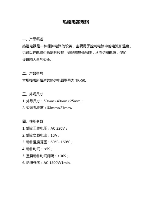
热继电器规格一、产品概述热继电器是一种保护电路的设备,主要用于控制电路中的电流和温度。
它可以在电路中检测到过载、短路和其他故障,从而切断电源,保护设备和人员的安全。
二、产品型号本规格书所描述的热继电器型号为TR-50。
三、外观尺寸1. 外形尺寸:50mm×40mm×25mm;2. 安装孔距离:33mm×21mm。
四、性能参数1. 额定工作电压:AC 220V;2. 额定负载电流:10A;3. 动作温度范围:60℃~160℃;4. 动作时间:≤5S;5. 重复动作时间间隔:≥30S;6. 绝缘强度:AC 1500V/1min.五、外部连接方式1. 输入端口:a) L1和L2接入交流220V供电线路;b) P1和P2接入负载线路。
2. 输出端口:a) C1和C2为输出端口,可接入控制回路。
六、使用注意事项1. 本产品应由专业人员安装并调试,确保正确接线和使用。
2. 在使用过程中应确保热继电器周围无遮挡物,以免影响散热效果。
3. 热继电器应安装在通风良好的干燥处,避免接触水分和潮气。
4. 在使用过程中如发现异常情况,应立即停止使用并进行检修或更换。
七、包装清单1. TR-50热继电器主机;2. 安装螺钉及螺母。
八、质保期本产品自出厂之日起质保期为一年,质保期内如出现非人为损坏的故障可享受免费维修或更换服务。
九、结论TR-50型号热继电器是一款具有可靠性和稳定性的保护设备,广泛应用于家电、工业控制等领域。
本规格书详细介绍了该产品的外观尺寸、性能参数、外部连接方式、使用注意事项等方面内容,使用户对该产品有更加全面和深入的了解。
热继电器
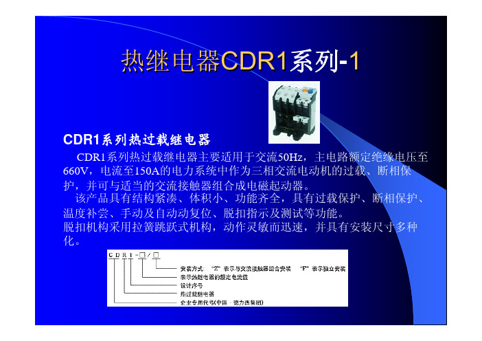
热继电器CDR1系列-1CDR1系列热过载继电器CDR1系列热过载继电器主要适用于交流50Hz,主电路额定绝缘电压至660V,电流至150A的电力系统中作为三相交流电动机的过载、断相保护,并可与适当的交流接触器组合成电磁起动器。
该产品具有结构紧凑、体积小、功能齐全,具有过载保护、断相保护、温度补尝、手动及自动动复位、脱扣指示及测试等功能。
脱扣机构采用拉簧跳跃式机构,动作灵敏而迅速,并具有安装尺寸多种化。
热继电器CDR1系列-2主要技术参数1、热继电器的动作特性和温度补偿性能2、热元件额定电流、电流范围见表热继电器CDR2系列-1CDR2系列热继电器一、适用范围CDR2系列热继电器主要适用于交流50Hz(60Hz),额定绝缘电压至660V额定电流至5 00A的电力线路中,用作三相感应电动机的过载与断相保护。
一般与CDC1(B) 系列交流接触器配合组成电磁起动器。
二、结构特征CDR2-16、25热继电器为磨擦脱扣式动作机构,带断相运转保护;CDR2-45、85为拉簧式脱扣动作机构(跳跃机构),带断相保护;CD R2-105、170为背包跳跃机构,CDR2-250、370为回路带互感器的跳跃进式机构,均带断相保护。
热继电器CDR2系列-2主要技术参数1、热继电器的动作特性和温度补偿性能2、热继电器型号规格及辅助触头参数热继电器CDR2系列-3 3、热元件额定电流、电流范围见表热继电器CDR2系列-4热继电器JRS1(LR1-D)系列-1JRS1系列热继电器适用于交流50Hz、主电路额定电压至660V、额定电流0.1至80A的电路中,供交流电动机的过载及断相保护用。
它具有差动机构和温度补偿动能,可与CJX2列交流接触器插接安装。
本产品为引进法国TE公司技术制造的产品。
热继电器JRS1(LR1-D)热继电器JRS1(LR1-D)系列-3热继电器JRS1(LR1-D)系列-4热继电器JRS2(3UA5)系列-1JRS2系列热过载继电器JRS2系列热过载继电器主要适用于交流50/60Hz 、电压至660V ,电压660V ,电流0.1~630A 的电力系统中,供三相交流异步电动机作过载和断相保护之用,热过载继电器还能与C JX1系列交流触器组合安装于封闭的壳体内,构成电磁起动器使用。
ABB TF42 热过载继电器 数据表
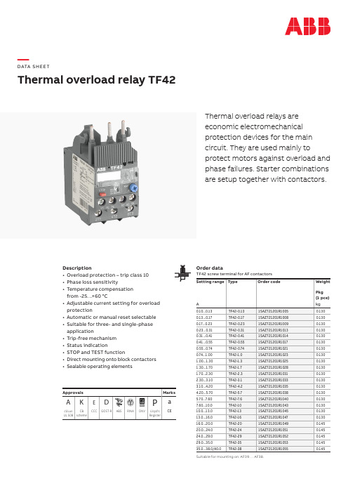
—DATA S H EE TThermal overload relay TF42Thermal overload relays areeconomic electromechanicalprotection devices for the maincircuit. They are used mainly toprotect motors against overload andphase failures. Starter combinationsare setup together with contactors.Description• Overload protection – trip class 10• Phase loss sensitivity• Temperature compensationfrom -25…+60 °C• Adjustable current setting for overload protection• Automatic or manual reset selectable • Suitable for three- and single-phase application• Trip-free mechanism• Status indication• STOP and TEST function• Direct mounting onto block contactors •Sealable operating elements Order dataTF42 screw terminal for AF contactorsSuitable for mounting on: AF09 … AF38.Approvals MarksA K ED P acULus UL 508CBschemeCCC GOST-R ABS RINA DNV Lloyd'sRegisterCEOperation modeWiring diagram3~1~979598962T14T26T3RESETA MTESTSTOPContact 95-96Contact 97-98Status indication CommentTrip state open closed RESET stateclosed open ONTEST manual reset mode open closed TEST auto reset modeopen closed while TEST is operated STOP while device is in trip state open closed STOP button has no function STOP while device is in RESET stateopenopenwhile STOP button is pressedApplication / internal functionThe thermal overload relays are three pole relays with bimetal tripping elements (1 per pole). The motor cur -rent flows through the bimetal tripping elements and heats them directly and indirectly. In case of an over -load (over current), the bimetal elements become bent as a result of the heating. This leads to a release of the relay and a change of the contacts switching position (95-96 / 97-98). The contact 95-96 is used to control the load contactor.The overload relays have a setting scale in Amperes, which allows the direct adjusting of the relay without any additional calculation. In compliance with inter -national and national standards, the setting current is the rated current of the motor and not the tripping current (no tripping at 1.05 x I, tripping at 1.2 x I; I = setting current). The relays are constructed in way that they protect themselves in the event of an over-load. The overload relay has to be protected against short-circuit. The appropriate short-circuit protective devices are shown in the table.ABB DATA SHEET THERMAL OVERLOAD RELAY TF42 3Resistance and power loss per pole and Short-circuit protective device TypeSetting range Resistance per polePower loss per pole Short-circuitprotection device coordination type 2lower value upper value at lower value at upper value A A m ΩW W TF42-0.130.10 0.13106508.88 1.1 2.00.5 A, Type T TF42-0.170.13 0.1762283.74 1.1 2.0 1.0 A, Type T TF42-0.230.17 0.2337429.00 1.1 2.0 1.0 A, Type T TF42-0.310.23 0.3120603.43 1.1 2.0 1.0 A, Type T TF42-0.410.31 0.4111421.77 1.1 2.0 2.0 A, Type gG TF42-0.550.41 0.556347.11 1.1 2.0 2.0 A, Type gG TF42-0.740.55 0.743615.62 1.1 2.0 4.0 A, Type gG TF42-1.00.74 1.001920.00 1.1 2.0 6.0 A, Type gG TF42-1.3 1.00 1.301065.09 1.1 2.0 6.0 A, Type gG TF42-1.7 1.30 1.70622.84 1.1 2.010.0 A, Type gG TF42-2.3 1.70 2.30340.26 1.1 2.010.0 A, Type gG TF42-3.1 2.30 3.10187.30 1.1 2.010.0 A, Type gG TF42-4.2 3.10 4.20102.04 1.1 2.020.0 A, Type gG TF42-5.7 4.20 5.7059.10 1.1 2.020.0 A, Type gG TF42-7.6 5.70 7.6031.16 1.1 2.035.0 A, Type gG TF42-107.60 10.0019.30 1.1 2.035.0 A, Type gG TF42-1310.00 13.0013.07 1.3 2.240.0 A, Type gG TF42-1613.00 16.007.79 1.3 2.240.0 A, Type gG TF42-2016.00 20.00 6.25 1.8 2.663.0 A, Type gG TF42-2420.00 24.00 4.51 1.8 2.663.0 A, Type gG TF42-2924.00 29.00 3.09 1.8 2.663.0 A, Type gG TF42-3529.00 35.00 2.25 2.1 2.880.0 A, Type gG TF42-3835.0040.001.722.12.880.0 A, Type gGTechnical diagrams(Op/h)s w i t c h i n g f r e q u e n cmultiple of setting current(s)Intermittent periodic duty, ta: Motor starting time Example of a tripping curve, starting from cold stateMain dimensions in mm, inches4 ABB DATA SHEET THERMAL OVERLOAD RELAY TF42Technical data IEC/ENData at T A = 40 °C and at rated values, if nothing else indicatedMain circuitTerminal marking2T1-4T2-6T3Rated operational voltage Ue690 V AC600 V DCSetting range - thermal overload protection see table on page 1Rated operational current AC-3 Ie see upper value of setting range, see table on page 3Trip class10Rated frequency50/60 HzNumber of poles3Resistance per pole see table on page 3Power loss per pole see table on page 3Short-circuit protective devices see table on page 3Isolation dataRated impulse withstand voltage Uimp 6 kVRated insulation voltage Ui690 VPollution degree3Electrical connectionTF42 ≤ 20 A TF42 > 20 Asolid1/2 x 0.75...4 mm²1/2 x 1.5...2.5 mm² / 1/2 x 2.5...10 mm²stranded1/2 x 0.75...4 mm²1/2 x 1.5...2.5 mm² / 1/2 x 2.5...10 mm²flexible with ferrule1/2 x 0.75...4 mm²1/2 x 1.5...2.5 mm² / 1/2 x 2.5...10 mm²flexible with ferrule insulated1/2 x 0.75...4 mm²1/2 x 1.5...6 mm²flexible without ferrule1/2 x 0.75...4 mm²1/2 x 2.5...4 mm² / 1/2 x 4...6 mm²Stripping length12 mmTightening torque 1.5…2.5 Nm 2.5…2.7 NmRecommended screw driver M4 (Pozidriv 2)ABB DATA SHEET THERMAL OVERLOAD RELAY TF42 5Auxiliary circuitTerminal marking95-96, 97-98Rated operational voltage Ue600 VConventional free air thermal current I th N.C., 95-96 6 A N.O., 97-98 4 ARated frequency DC, 50/60 Hz Number of poles 1 N.C. + 1 N.O. Rated operational current le acc. toIEC/EN 60947-5-1 for utilization categoryat AC-15 at 110-120 V N.C., 95-96 3.00 AN.O., 97-980.5 Aat AC-15 at 220-230-240 V N.C., 95-96 3.00 AN.O., 97-980.5 Aat AC-15 at 440 V N.C., 95-960.75 AN.O., 97-980.5 Aat AC-15 at 480-500 V N.C., 95-960.75 AN.O., 97-980.5 Aat DC-13 at 24 V N.C., 95-96 1.25 AN.O., 97-98 1.25 Aat DC-13 at 110-120-125 V N.C., 95-960.55 AN.O., 97-980.55 Aat DC-13 at 250 V N.C., 95-960.27 AN.O., 97-980.27 Aat DC-13 at 500 V N.C., 95-960.15 AN.O., 97-980.15 AMinimum switching capacity17 V / 3 mAShort-circuit protective device N.C., 95-96 6 A, Type gGN.O., 97-98 4 A, Type gG Isolation dataRated impulse withstand voltage Uimp 6 kVRated insulation voltage Ui690 VPollution degree3Electrical connectionsolid1/2 x 0.75...4 mm²stranded1/2 x 0.75...4 mm²flexible with ferrule1/2 x 0.75...2.5 mm²flexible with ferrule insulated 1 x 0.75...2.5 mm²2 x 0.75...1.5 mm²flexible without ferrule1/2 x 0.75...1 mm²1/2 x 1...2.5 mm²Stripping length9 mmTightening torque 1...1.5 Nm Recommended screw driver M3 (Pozidriv 2)6 ABB DATA SHEET THERMAL OVERLOAD RELAY TF42General dataDuty time100 %Operating frequency without early tripping up to 15 operations/h or 60 operations/h with 40 % duty ratio, if the motorbreaking current 6 x In and the motor starting time does not exceed 1 s Dimensions (W x H x D)see drawing "Dimensions"Weight see table "Order data"Mounting mount on the contactor and tighten the screws of the main circuit terminalsor with single mounting kit on DIN rail (35 mm)Mounting position position 1-5Minimum distance to other units same type horizontal nonevertical not applicableMinimum distance to electrical conductive board horizontal nonevertical on requestDegree of protection houisng IP20Altitude main circuit terminals up to 2000 mElectromagnetic compatibilityElectromagnetic compatibility not applicable Environmental dataAmbient air temperatureOperation open - compensated-25...+60 °C (> 38 A: -25...+50 °C)open-25...+60 °C (> 38 A: -25...+50 °C) Storage-50...+80 °CAmbient air temperature compensation acc. to IEC/EN 60947-4-1 Resistance to vibrations acc. to IEC 60068-2-6 (Fc)5g / 3...150 HzResistance to shock acc. to IEC 60068-2-27(Ea)25g / 11 msStandards / directivesStandards IEC/EN 60947–4–1IEC/EN 60947-5-1IEC/EN 60947-1UL 508, CSA 22.2 No. 14Low Voltage Directive2006/95/ECEMC Directive2004/108/ECRoHS Directive2002/95/ECABB DATA SHEET THERMAL OVERLOAD RELAY TF42 7Technical data UL/CSAMain circuitType Full load amps(FLA)Short-circuit protective device480 / 600 V AC480 / 600 V ACSCCR Fuse type SCCR Fuse typeTF42-0.130.13 A18 kA 1 A, K5100 kA30 A, Class J TF42-0.170.17 A18 kA 1 A, K5100 kA30 A, Class J TF42-0.230.23 A18 kA 1 A, K5100 kA30 A, Class J TF42-0.310.31 A18 kA 3 A, K5100 kA30 A, Class J TF42-0.410.41 A18 kA 3 A, K5100 kA30 A, Class J TF42-0.550.55 A18 kA 3 A, K5100 kA30 A, Class J TF42-0.740.74 A18 kA 3 A, K5100 kA30 A, Class J TF42-1.0 1.00 A18 kA 6 A, K5100 kA30 A, Class J TF42-1.3 1.30 A18 kA 6 A, K5100 kA30 A, Class J TF42-1.7 1.70 A18 kA 6 A, K5100 kA30 A, Class J TF42-2.3 2.30 A18 kA10 A, K5100 kA30 A, Class J TF42-3.1 3.10 A18 kA10 A, K5100 kA30 A, Class J TF42-4.2 4.20 A18 kA15 A, K5100 kA30 A, Class J TF42-5.7 5.70 A18 kA20 A, K5100 kA30 A, Class J TF42-7.67.60 A18 kA25 A, K5100 kA30 A, Class J TF42-1010.0 A18 kA35 A, K5100 kA45 A, Class J TF42-1313.0 A18 kA40 A, K5100 kA45 A, Class J TF42-1616.0 A18 kA60 A, K5100 kA45 A, Class J TF42-2020.0 A18 kA80 A, K5100 kA60 A, Class J TF42-2424.0 A18 kA80 A, K5100 kA60 A, Class J TF42-2929.0 A18 kA100 A, K5100 kA100 A, Class J TF42-3535.0 A18 kA150 A, K5100 kA175 A, Class J TF42-3838.0 A18 kA150 A, K5100 kA175 A, Class JMain circuitMax. operational voltage600 V ACTrip rating125% of FLAFull load amps (FLA)see table aboveShort-circuit rating RMS symmetrical see table aboveShort-circuit protective device see table aboveElectrical connectionTF42 ≤ 20 A TF42 > 20 AConnecting capacitystranded1/2 x AWG 18...101/2 x AWG 14 (6)flexible without ferrule1/2 x AWG 18...101/2 x AWG 14 (6)Stripping length12 mmTightening torque13...22 Ib-in22 Ib-inAuxiliary circuitConventional thermal current N.C., 95-96 5 AN.O., 97-98 2.5 AMaking and breaking capacity N.C., 95-96B600, Q300N.O., 97-98D300, Q300Electrical connectionConnecting capacitystranded1/2 x AWG 18 (12)flexible without ferrule1/2 x AWG 18 (12)Stripping length9 mmTightening torque9...13 Ib-in2C D C 106023D 0202 - (03.2021 P D F )—You can find the address of your local sales organization on the ABB home pagehttps:///low-voltage/products/ motor-protection/manual-motor-starter—ABB STOTZ-KONTAKT GmbH Electrification BusinessLow Voltage Products and Systems Eppelheimer Straße 82D-69123 Heidelberg / Germany Phone: +49 (0) 6221 7 01-0 Fax: +49 (0) 6221 7 01-13 25E-Mail:*****************.comWe reserve the right to make technical changes or modify the contents of this document without prior notice.With regards to purchase orders, the agreed particulars shall prevail. ABB AG does not accept any responsibility whatsoever for potential errors or possible lack of information in this document.We reserve all rights in this document and in the subject matter and illustrations contained therein. Anyreproduction, disclosure to third parties or utilization of its contents – in whole or in parts – is forbidden without prior written consent of ABB AG.Copyright© 2021 ABB - All rights reserved。
21.热继电器
图1-21 双金属片式热继电器的结构示意图
4 型号、符号及主要参数
(1)型号。热继电器的型号标志组成及其含义如下:
JR 16 热继电器
设计序号
/ 热元件编号 特征代号: D—带断相保护 L—单独安装式 Z—与交流接触器组合接线安装式 W—带专用配套电流互感器
基本规格代号(以额定整定电流表示)
4 型号、符号及主要参数
目 录:
1 热继电器的分类 2 热继电器的结构 3 热继电器的工作原理 4 型号、符号及主要参数 5 选择、常见故障及处理方法
3
1
热继电器的分类
按相数来分,热继电器有单相、两相和三相式三种类型。 按功能来分,三相式的热继电器又有带断相保护装置和 不带断相保护装置的。 按复位方式分,热继电器有自动复位的和手动复位的, 所谓自动复位是指触头断开后能自动返回。 按温度补偿分,有带温度补偿的和不带温度补偿的。
图1-21 双金属片式热继电器的结构示意图
3 热继电器的工作原理
工作原理: 当电动机正常运行时,其工作电流通过热元件 产生的热量不足以使双金属片变形到位,热继电器 不会动作。当电动机发生过电流且超过整定值时, 双金属片受热量增大而发生弯曲,经过一定时间后, 使触点动作,通过控制电路切断电动机的工作电源。 热继电器动作后一般不能自动复位,要等双金属片 冷却后按下复位按钮复位。
热继电器不动作
1. 整定电流偏大 2. 热元件烧断或脱焊 3. 导板脱出
1. 调小整定电流 2. 更换热元件或热继电器 3. 重新放置导板并试验动作灵活性
5 选择、常见故障及处理方法
热继电器的常见故障及其处理方法如表1-11所示。
表1-11 热继电器的常见故障及其处理方法
故障现象 热元件烧断 主电路不通 控制电路不通
接触器与热继电器选型表

99A
常熟富士 电动机接触器与热继电器选型表
序号
功率
断路器
直接启动
星三角启动
备注
接触器
热继电器
整定值
接触器*2
接触器
热继电器
整定值
1
0.15
BC63E1DG-3P016
SC-E02 +SZ-A11
TK-E02H-C 0.0.48~0.72
0.56A
2
0.3
BC63E1DG-3P016
7A
12
9
S263-D25A
A30-30-10*80+CA5-22M
TA42 DU25
18A
A30-30-10*80+CA5-22M
A16-30-10*80+CA5-22M
TA25 DU8.5
9A
13
11
S263-D32A
A30-30-10*80+CA5-22M
TA42 DU25
22A
A30-30-10*80+CA5-22M
CJR3-25 U 6~9
6.6A
9
3.7
CH1-63 D16/3
CK3-09+FSZ-A11
CJR3-25 V 7~11
8A
10
5.5
CH1-63 D20/3
CK3-12+FSZ-A11
CJR3-25 W 9~13
12A
11
7.5
CH1-63 D25/3
CK3-18+FSZ-A11
CJR3-25 X 12~18
SC-E02 +SZ-A11
TK-E02P-C 2.2~3.4
电机与热继电器参数配置
电机与热继电器参数配置下载温馨提示:该文档是我店铺精心编制而成,希望大家下载以后,能够帮助大家解决实际的问题。
文档下载后可定制随意修改,请根据实际需要进行相应的调整和使用,谢谢!并且,本店铺为大家提供各种各样类型的实用资料,如教育随笔、日记赏析、句子摘抄、古诗大全、经典美文、话题作文、工作总结、词语解析、文案摘录、其他资料等等,如想了解不同资料格式和写法,敬请关注!Download tips: This document is carefully compiled by the editor. I hope that after you download them, they can help yousolve practical problems. The document can be customized and modified after downloading, please adjust and use it according to actual needs, thank you!In addition, our shop provides you with various types of practical materials, such as educational essays, diary appreciation, sentence excerpts, ancient poems, classic articles, topic composition, work summary, word parsing, copy excerpts,other materials and so on, want to know different data formats and writing methods, please pay attention!电机与热继电器参数配置在现代工业生产中扮演着重要的角色。
热继电器参数详解

热继电器参数详解热继电器是一种常见的电气控制元件,它可以通过加热元件和温度感应元件来实现自动开关电路的功能。
在使用热继电器之前,我们需要了解一些相关的参数,以确保正确选择和使用。
1. 额定电流(Rated Current):这是指热继电器所能承受的最大电流值。
在选购时,我们需要确定所需的负载电流,以确保选用的热继电器具有足够的额定电流。
2. 额定电压(Rated Voltage):热继电器能够承受的最大电压值。
我们应该确保热继电器的额定电压与所需应用的电压匹配。
3. 额定功率(Rated Power):热继电器所能承受的最大功率值,它是额定电流和额定电压的乘积。
选择热继电器时,应该确保它的额定功率大于或等于所需应用的功率。
4. 动作时间(Operating Time):热继电器的动作时间是指控制电路中的温度达到触发点后,热继电器切换状态所需的时间。
5. 断开时间(Release Time):热继电器的断开时间是指控制电路中温度下降到切断点以下后,热继电器切换状态所需的时间。
6. 动作电压(Operating Voltage):指控制电路中热继电器动作所需的电压。
我们需要确保提供足够的动作电压以确保热继电器的正常工作。
7. 隔离电压(Isolation Voltage):热继电器能够隔离的最大电压。
这是为了确保控制电路和被控制电路之间的电气隔离,以防止电压干扰和短路。
8. 接触电阻(Contact Resistance):接触电阻是指热继电器在闭合状态下接触点之间的电阻,它对电气传导和导热性能有影响。
较低的接触电阻可以提高热继电器的性能。
这些参数是选择和使用热继电器时需要考虑的重要因素。
准确理解和合理选择这些参数可以确保热继电器的可靠性和性能,从而实现我们期望的电气控制功能。
热继电器

原来的规格与要求。
谢谢观看
原则上热继电器的额定电流应按电 动机的流来调整它的整定值。
双金属片式热继电器一般用于轻载、 不频繁启动电动机的过载保护。
六、热继电器的日常维护
01 02
热继电器动作后复位需
要一定的时间,自动复 位时间应在 5min 内完成, 手动复位要在 2min 后才 能按下复位按钮。
二、工作原理
双金属片
~
常闭触头
发热元件 结构原理图
杠杆
发热元件接入 电机主电 路 , 若长 时间过载 ,双金属 片被加热 。因双金 属片的下 层膨胀系 数大,使 其向上弯 曲, 杠杆 被弹簧拉 回,常闭触点断开。
热继电器的工作过程演示
三、热继电器的符号
常开触点
(a) 热元件; (b) 常闭触点 热继电器的图形及文字符号
四、热继电器的主要参数
热继电器的整定电流
热元件在正常持续工作中不引起热继电 器动作的最大电流值。整定电流的大小可以 通过整定旋钮来调整。
四、热继电器的主要参数
热元件的额定电流
热元件的最大整定电流值。
五、热继电器的选用
一般选择两相或者普通三相结构的 热继电器;三角形连接的电动机选 用带断相保护装置的三相热继电器。
低压电器 —热继电器
QIAN
前 言
YAN
在电力拖动控制系统中, 热继电器是
对电动机在长时间连续运行过程中过载及 断相起保护作用的电器。
教学主要内容
1 2
结构 工作原理 热继电器的符号 热继电器的主要参数 热继电器的选用
3
4
5
6
热继电器的日常维护
一、结构
热继电器由双金属片、热元件、动作机构、触头系统、 整定调整装置和手动复位装置组成
- 1、下载文档前请自行甄别文档内容的完整性,平台不提供额外的编辑、内容补充、找答案等附加服务。
- 2、"仅部分预览"的文档,不可在线预览部分如存在完整性等问题,可反馈申请退款(可完整预览的文档不适用该条件!)。
- 3、如文档侵犯您的权益,请联系客服反馈,我们会尽快为您处理(人工客服工作时间:9:00-18:30)。
热继电器参数对照表
1. 额定电流(Rated Current),指热继电器能够承受的最大电流值。
单位通常为安培(A)。
2. 额定电压(Rated Voltage),指热继电器能够正常工作的电压范围。
单位通常为伏特(V)。
3. 动作电流(Pick-up Current),指热继电器开始动作的电流值。
一般情况下,动作电流小于或等于额定电流。
4. 释放电流(Drop-out Current),指热继电器停止动作的电流值。
一般情况下,释放电流小于或等于动作电流。
5. 动作时间(Pick-up Time),指热继电器从开始动作到完全动作所需的时间。
单位通常为毫秒(ms)。
6. 释放时间(Drop-out Time),指热继电器从停止动作到完全停止所需的时间。
单位通常为毫秒(ms)。
7. 绝缘电阻(Insulation Resistance),指热继电器在特定
条件下的绝缘电阻值。
单位通常为兆欧姆(MΩ)。
8. 工作温度范围(Operating Temperature Range),指热继电器能够正常工作的温度范围。
通常以摄氏度(℃)表示。
9. 安装方式(Mounting Type),指热继电器的安装方式,如插座安装、螺丝固定等。
10. 电气生命(Electrical Life),指热继电器在特定条件下能够正常工作的时间。
单位通常为次数。
11. 机械生命(Mechanical Life),指热继电器在特定条件下能够正常工作的次数。
单位通常为次数。
12. 接点类型(Contact Type),指热继电器的接点类型,如常开(NO)、常闭(NC)或双刀双掷(DPDT)等。
以上是热继电器参数对照表的一些常见参数及其含义。
不同型号的热继电器可能会有不同的参数,具体的参数还需根据具体的产品手册或规格表来确定。