沙特阿美工程规程SAEP
沙特阿美工程规程SAEP-134
Previous Issue: 15 October 2008 Next Planned Update: 15 October 2013Revised paragraphs are indicated in the right marginPage 1 of 5 Primary contact: Ghulam, Ziad Mohammad Jamil on 966-3-8745670Engineering ProcedureSAEP-134 4 March 2009 Preparation of Saudi Aramco Engineering ProceduresDocument Responsibility: Standards CoordinatorSaudi Aramco DeskTop StandardsTable of Contents1 Scope (2)2 Applicable Documents (2)3 Instructions (2)4 Responsibilities (4)Next Planned Update: 15 October 2013 Preparation of Saudi Aramco Engineering Procedures1 ScopeSaudi Aramco Engineering Procedures (SAEPs) establish instructions andresponsibilities associated with various engineering activities. This document contains the instructions to initiate, format, prepare, revise, coordinate and obtain approvals forall SAEPs.SAEPs are procedures, approved by Saudi Aramco Management, that establishminimum requirements for dealing with their associated subject material. They aremandatory and apply on a Company-wide basis.2 Applicable DocumentsThe requirements contained in the following documents apply to the extent specified in this procedure:Saudi Aramco Engineering ProceduresSAEP-301 Instructions for Establishing and MaintainingMandatory Saudi Aramco EngineeringRequirementsSAEP-302 Instructions for Obtaining a Waiver of a MandatorySaudi Aramco Engineering Requirement3 Instructions3.1 PurposeThe purpose of a SAEP is to establish and approve a systematic method orprocess of accomplishing an engineering related activity.3.2 Organization and Contents3.2.1 The content of each SAEP is to be divided and the material organizedinto a minimum of four mandatory sections:∙Scope: This section of the procedure is normally used to describe thesubject matter of the document, including the extent of itsapplication. It can also make an overall general statementencompassing the content or functional intent of the SAEP.∙Applicable Documents: This section lists all documents that arereferenced within the procedure. Do not list documents that are notreferred to.Next Planned Update: 15 October 2013 Preparation of Saudi Aramco Engineering Procedures ∙Instructions: This section provides the procedure's instructions orguidelines to be followed.∙Responsibilities: This section establishes the responsibilities,authority and approvals associated with carrying out the procedure'sinstructions.3.2.2 Additional sections may be included as necessary, depending upon thesubject matter involved. Add more sections only when it is necessary toinclude material that does not logically fit within one of the mandatorysections.3.2.3 Appendices may be included to provide information in support of themain text of the SAEP. This may include tables, charts, graphs,examples, etc. Do not include Saudi Aramco forms in the procedure.Instead, make reference to them by their form number.Identify appendices as Appendix A, B, etc., on consecutively numberedpages. Locate appendices after the last page of the last SAEP sectionand list each appendix in the Table of Contents.3.3 Deviation from Procedure RequirementsApproval to deviate from the requirements given in a SAEP shall be obtained byfollowing the waiver instructions of SAEP-302.3.4 Cancellation of SAEPCancel existing SAEPs by obtaining the signature of the procedure's ApprovalAuthority.3.5 Document NumberingDocument numbers will be assigned to SAEPs based on the following:∙Two digit numbers: Approval by Senior Vice President∙Three digit numbers: Approval by Vice President or Chief Engineer∙Four digit numbers: Approval by Department ManagerThe mechanism of determining the document number of an engineeringprocedure will be based on the safety, cost, and maintenance and operationsimpact of the procedure. It will be supported and based on the followingfundamental nature:a) If the procedure will be utilized solely by the Saudi Aramco ResponsibleNext Planned Update: 15 October 2013 Preparation of Saudi Aramco Engineering ProceduresOrganization (who develops the procedure), a four digit number will beassigned and approval shall be by the Department Manager.b) If the procedure will be utilized by other department(s) within the sameadmin. area aside from the SARO, a three digit number will be assignedand the approval shall be by the Vice President or Chief Engineer.c) If the document will be utilized by other department(s) belonging to otherbusiness line(s), a two digit number will be assigned and the approval shallbe by the Sr. Vice President of the proponent organization.Commentary Note:The Saudi Aramco Responsible Organization (SARO) should evaluate the costimplication as a result of developing a two-digit procedure.4 Responsibilities4.1 Saudi Aramco Responsible Organization (SARO)The SARO is the department responsible for the procedure. All SAEPs musthave an assigned SARO. Specific responsibilities of the SARO include:∙Determine the need for new SAEPs, and review existing SAEPs, at least once every five (5) years per SAEP-301, to determine if they are still valid.Where required, revise procedures to achieve broadest company-wideapplication, maintain overall cost-effectiveness, ensure technical adequacy,and generally keep them up-to-date.∙Determine the approval authority for the procedure.∙Determine if company-wide input is needed for procedures containing major revisions or new SAEPs.∙Forward draft documents to the Standards Coordinator to either route for BOE review or for the completion of approval, publication, and distributionprocesses per SAEP-301 paragraph 4.7(g).∙Forward all original approval copies of procedures to the StandardsCoordinator for historical filing. Include other documents judged importantenough to be kept with the document file.4.2 Board of Engineers (BOE)∙Review SAEPs as required by paragraph 4.1, ensuring they are acceptable from the technical, safety, economic and implementation standpoint.Next Planned Update: 15 October 2013 Preparation of Saudi Aramco Engineering Procedures ∙Recommend to the Approval Authority, appropriate changes to achieve an optimum balance of technical, safety, economic and implementation factors.4.3 Approval AuthorityThe Approval Authority, determined by the SARO for each procedure, shallreview each procedure to ensure that the final procedure should be approved foruse. For documents reviewed by the BOE, ensure that all major comments havebeen resolved.4.4 Standards CoordinatorThe Standards Coordinator is responsible for the administration of all SAEPs.Specific responsibilities include:∙Maintain accurate records of all approved SAEPs, including issue dates and next planned revisions. Keep historical files and copies of all SAEPs,including original document approval signatures.∙Assign document numbers to new SAEPs.∙Establish document format and content requirements. Review all SAEPs prior to final approval for conformance to these requirements.∙Forward draft SAEPs to the BOE for review, and final revised SAEPs to the document's Approval Authority.∙Approve minor editorial changes to the procedure for such things astypographical errors, organization name and title changes approved byManagement, and reference document name changes.∙Disseminate the information of all approved SAEPs per SAEP-301paragraph 4.7(g).∙Notify SARO representatives of approaching planned revision dates insufficient time to allow an orderly review and rewrite of the procedure, ifrequired.Revision Summary15 October 2008 Revised the "Next Planned Update." Reaffirmed the contents of the document, andreissued with editorial changes.4 March 2009 Editorial revision to clarify Section 3.5 (Document Numbering).。
沙特阿美集输管道项目现场外防腐施工技术
沙特阿美集输管道项目现场外防腐施工技术摘要:沙特阿美的质量管理体系以严格著称,承接阿美公司的管道施工项目,有必要掌握相关其质量标准和施工技术。
本文结合沙特NGCP项目实际施工经验,主要介绍了管道环焊缝防腐补口和场站工艺管道喷漆施工对于人员资质、材料选用、施工要点、检验要求以及注意事项等,以期对类似工程的施工开展提供指导和借鉴。
关键词:沙特阿美环焊缝补口工艺管道喷漆依据沙特阿美标准,油气管道和场站现场防腐必须选用APCS(Aramco Approved Coating System)体系认证的涂层系统进行防腐作业。
防腐作业工序是阿美业主最为重视的工序之一,直接影响未来油气设施的安全运行,也是项目验收阶段业主PMCC(Partial Mechanical Completion Certificate)业主给出最多需要关闭的尾项,因此对于承包商来说,不论前期还是后期,防腐施工都是影响项目成败的关键工序,必须给与足够的重视。
本文根据沙特NGCP项目施工经验和质量管理经验,结合阿美标准要求,对集输管道环焊缝补口补伤施工和场站喷漆施工技术进行介绍,以期对类似项目提供经验借鉴。
1 人员资质阿美程序文件SAEP-316要求,所有现场执行表面处理、防腐、验收作业的人员必须通过阿美认证[1]。
现场施工作业必须配备通过阿美认证的防腐机组长,专职质检员(分为一级和二级质检员),沙特NGCP项目合同要求现场配备二级质检员。
冷缠工、喷砂工、喷漆工需要通过现场演示考试,取得JCC(Job Clearance Card)卡, 方能进入作业现场进行工作。
面试和考试都需要提交证明材料和一定的时间(至少1个星期),所以根据工程进度要提前谋划和考虑。
2 现场环焊缝补口2.1 材料选用与国内工程惯常使用使用聚乙烯胶黏带不同,沙特埋地管道环焊缝补口可以应用113C系统(冷缠带)也可以使用系统113A(高粘度环氧漆)。
出于施工便利性,工程采用冷缠带施工进行补口。
沙特阿美工程规程SAEP-27 Pipelines Piping Hydraulic Surge Analysis
Previous Issue: New Next Planned Update: 19 July 2014Page 1 of 14 Primary contact: on 966-3-8730674Engineering ProcedureSAEP-27 19 July 2009Pipelines/Piping Hydraulic Surge AnalysisDocument Responsibility: Process and Control Systems Dept.Saudi Aramco DeskTop StandardsTable of Contents1 Scope (2)2 Conflicts and Deviations (2)3 Applicable Documents (2)4 Definitions (4)5 Instructions (5)6 Responsibilities (11)Exhibits (12)Next Planned Update: 19 July 2014 Pipelines/Piping Hydraulic Surge Analysis1 ScopeThis Saudi Aramco Engineering Procedure (SAEP) provides technical guidance todefine full scope of hydraulic surge analysis during DBSP, Project Proposal, DetailedDesign and throughout the different stages of a project cycle and throughout theoperational life of a pipeline to ensure consistent approach. It provides Saudi Aramcoengineers and engineering design contractors with guidelines describing therequirements to conduct and review pipelines hydraulic surge analysis studies forexisting and new facilities.2 Conflicts and Deviations2.1 Any conflicts between this standard and other applicable Saudi AramcoEngineering Standards (SAESs) or industry standards, codes, and forms shall beresolved in writing through the Manager, Process & Control Systems Departmentof Saudi Aramco, Dhahran.2.2 Direct all requests to deviate from this standard in writing to the Company, whoshall follow internal company procedure SAEP-302 and forward such requests tothe Manager, Process & Control Systems Department of Saudi Aramco, Dhahran.3 Applicable DocumentsTo ensure compliance with the appropriate Saudi Aramco and International Standardsand Codes for over pressure protection of pipelines, the following EngineeringStandards shall be reviewed in conjunction with hydraulic surge analysis studies. These Standards encompass hydraulic analysis, surge analysis, over pressure protection ofpipelines, design pressure, materials, operating conditions, Maximum AllowableOperating Pressures and Maximum Allowable Surge Pressures.3.1 Saudi Aramco ReferencesSaudi Aramco Engineering ProceduresSAEP-12 Project Execution PlanSAEP-14 Project ProposalSAEP-302 Instructions for Obtaining a Waiver of aMandatory Saudi Aramco EngineeringRequirementSAEP-303 Engineering Reviews of Project Proposal andDetail Design DocumentationNext Planned Update: 19 July 2014 Pipelines/Piping Hydraulic Surge Analysis SAEP-354 High Integrity Protective Systems DesignRequirementsSAEP-363 Pipeline Simulation Model Development andSupportSaudi Aramco Engineering StandardsSAES-B-017 Fire Water System DesignSAES-B-058 Emergency Shutdown, Isolation, and DepressuringSAES-B-060 Fire Protection for Piers, Wharves and SeaIslandsSAES-B-064 Onshore and Nearshore Pipeline SafetySAES-B-070 Fire and Safety Requirements for Bulk PlantsSAES-J-600 Pressure Relief DevicesSAES-J-601 Emergency Shutdown and Isolation SystemsSAES-J-605 Surge Relief Protection SystemsSAES-J-700 Control ValvesSAES-L-100 Applicable Codes and Standards for PressurePiping SystemsSAES-L-132 Material Selection of Piping SystemsSAES-L-310 Design of Plant PipingSAES-L-410 Design of PipelinesSaudi Aramco Engineering ReportsSAER-5437 Guidelines for Conducting HAZOP StudiesSAER-6043 High Integrity Protection System (HIPS)Evaluation Team Report3.2 International Standards and CodesANSI/ASME Code “Process Piping” Chemical plant and petroleum refinerypipeline for in-plant pipingANSI/ASME B16.5 Pipe Flanges and Flanged FittingsANSI/ASME B31.1 Power PipingANSI/ASME B31.3 Chemical Plant and Petroleum Refinery Pipelineor In-Plant PipingNext Planned Update: 19 July 2014 Pipelines/Piping Hydraulic Surge Analysis ANSI/ASME B31.4 Liquid Petroleum Transportation Piping Systemsfor Cross-Country Liquid PipelinesANSI/ASME B31.8 Gas Transmission and Distribution PipingSystemsAmerican Petroleum InstituteAPI STD 521 Pressure-Relieving and Depressuring Systems American Water Works AssociationAWWA M45 American Water Works Association, FiberglassPipe DesignNational Fire Protection AssociationNFPA 24 Installation of Private Fire Services Mains andtheir AppurtenancesNFPA 25 Inspection, Testing and Maintenance of Waterbased Fire Protection Systems4 DefinitionsHydraulic Surge:Also referred to as “water hammer.” This is a phenomenon inpipeline operations characterized by a sudden increase in internal pressure. Hydraulicsurge is often caused by the transformation of kinetic energy to potential energy as astream of fluid is suddenly stopped.Surge Analysis: An engineering study that is undertaken to perform a hydraulic transient analysis of a specific system through the use of specialized simulation software whichmodels the system, fluid and operating conditions. The transient analysis will predict the time history of pressures and flows throughout a system as a result of potentiallyapplicable transient events. From the results, an experienced engineer/specialist candetermine whether additional surge protection is required, what form of surge protection is most suitable, its capacity and where it should be located. The surge/transient analysis referred to in this Standard is specific to pipelines/piping systems.HAZOP (Hazard and Operability): A systematic, detailed analysis technique applied to identify hazards and operability issues which have the potential to place the process plant, environment or personnel at risk. The HAZOP study identifies abnormal process deviations that may require additional protective functions. The HAZOP analysis shall follow the guidelines of SAER-5437, Saudi Aramco HAZOP Engineering Report.PHA (Preliminary Hazards Analysis): An initial screening exercise that can be used to identify, describe, and rank major hazards. This technique can also be used toNext Planned Update: 19 July 2014 Pipelines/Piping Hydraulic Surge Analysis identify possible consequences and likelihood of occurrence and providerecommendations for hazard mitigation.5 Instructions5.1 General Requirements5.1.1 PMT shall provide a copy of this Engineering Procedure to theEngineering design contractor involved in conducting the hydraulic andsurge analysis study and a full comply to this procedure shall be notifiedto the contractor.5.1.2 Risk assessment studies such as PHA or HAZOP, if available, shall beused as a basis for the surge analysis. The whole risk assessment (PHAand HAZOP) shall be an exercise in which all concerned parties(stakeholder organizations) are involved in sharing awareness andresponsibility for the decisions and assumptions made to commence thesurge analysis study. The risk assessment shall be conducted as definedin SAEP-12, SAEP-14 and SAEP-303.5.1.3 The engineering design contractor shall use the approved pipelinesimulation software that is defined in the Saudi Aramco RecommendedSimulation Software Vendor List. The approved list can be obtainedfrom P&CSD/Pipelines & Simulation Unit.5.1.4 At the completion of the hydraulic surge studies, the engineering designcontractor shall submit an electronic copy of complete simulation modelsand supporting documents to P&CSD/Pipelines & Simulation Unit, theProponent and FPD for review and approval.5.2 Surge Analysis Preparation ProceduresThe hydraulic surge analysis study shall be undertaken if over pressure ortransient risks to piping or pipelines are identified in the following phases of aproject or where changes to operating conditions are made including:1) Conceptual and Feasibility studies have been completed, detailed engineeringdesign such as DBSP, Project Proposal and Detailed Design is in progress.2) Prior to any change in existing pipeline operation or modification to thepipeline system. If the maximum flow rates or maximum operatingpressures increased from the previous operation, a new surge analysis at thenew conditions to ensure that the pipeline system is protected.3) Any change or equipment data update in the detailed design, final pipelinedesign, at the last minute, or during construction works.Next Planned Update: 19 July 2014 Pipelines/Piping Hydraulic Surge Analysis4) During commissioning and start up activities, especially for testing sectionsof the pipeline system or if the tested system is different from the standarddesign configuration.The study shall not be limited to the mentioned transient risk situations andP&CSD shall endorse the hydraulic surge analysis study timing.Before the surge analysis commences, a technical specification for the surgeanalysis study shall be prepared and approved by Proponent or SAPMT’sengineering contractor to acknowledge the problem for further assessment,scope development, and possible surge protection solution. The following listshall be completed to define full scope of the surge analysis for pipelines toensure a consistent approach for all projects.5.2.1 Analysis ObjectiveThe objective of the analysis will determine the extent of the pipelinesystem to be modeled and the accuracy of data required during pipelinemodel development and evaluation. A clear surge analysis objectiveshall be prepared and agreed with the pipeline hydraulic and surgeanalysis specialist of P&CSD prior to conducting the analysis.5.2.2 Pipeline System ScopeHydraulic surge analysis shall not be limited by project scope of work.The whole pipeline system needs to be analyzed and the model built forhydraulic surge analysis shall include all the possible causes from withinor beyond project scope boundaries and interfaces with other relatedfacilities.5.2.3 Possible Scenarios of Surge AnalysisThe transient/surge flow conditions that are expected to occur shall bedefined. The analysis shall look at various possible causes, identify thecritical cases, specify and design the necessary surge protection systemas identified during the PHA, HAZOP and surge analysis studies.Exhibit II shall be used as a checklist to identify potential causes oftransient pressure. As a minimum the following potential causes ofliquid piping overpressure shall be investigated:a) Inadvertent closure of a pipeline Class-1 or Class-2 valve.b) Closure of a downstream plant ESD valve.c) Trip of intermediate pump.Next Planned Update: 19 July 2014 Pipelines/Piping Hydraulic Surge Analysisd) Closure of one looped pipeline.e) Closure of more than one looped pipeline.f) Closure of isolation valves, inside interfacing, upstream anddownstream.g) Closure or control failure of a pipeline or downstream control valve.h) Inadvertent start of a standby pump, in addition to existing pump(s)operationi) Impact of new pipeline interfacing with existing pipeline5.2.4 Data RequirementsThe following list identifies data that shall be gathered before a surgeanalysis study is conducted:a) Pipeline system data: General description of the pipeline system,function and a summary of the likely hazard scenarios as identifiedin the PHA and HAZOP studies. Pipeline data including length,elevation profile, diameter, wall thickness, roughness or frictionfactor, elastic (Young’s) modulus, pressure rating, maximumpermissible pressure (pipes, components, joints, support), minimumacceptable pressure (pipes, components, joints, supports).b) Operating conditions: pipeline inlet pressure and temperature,arrival pressure, maximum and minimum flow rates.c) Fluid data: The key data required are the physical properties at therelevant operating pressure and temperature for the evaluatedpipeline system. Physical properties include: density, viscosity, truevapor pressure, bulk modulus, working temperature. Alternatively,for compositional analysis, the fluid composition shall be defined.d) Ambient conditions (summer/winter temperatures), thermalconductivities for pipelines and soil and/or the overall heat transfercoefficient between the pipeline and soil.e) Pumps: Type, number, location, performance characteristics, withoperating curves and the following rated conditions: (head, flow,speed, power and efficiency), Inertia of rotating elements (impeller,motor and coupling)f) Valves: Type, number, location, dynamic performance characteristic(Cv curve), open/close time, pressure rating and maximumpermissible pressure. Additional data for pressure relief valves: setNext Planned Update: 19 July 2014 Pipelines/Piping Hydraulic Surge Analysispressures for opening and closing, time needed to open and close,discharge pressure.g) Tanks: Location, general layout, dimensions, maximum, minimumand normal levels of the liquid surface, elevation relative to themain pipeline, length and diameter of the connecting piping.h) Bypass piping: Location, length, diameter, head loss.i) Surge and transient event data: Time scale of valve and pumpsoperation (Control Logic) and sequence of events to be investigated.j) Units of measurements must be consistent.5.2.5 Surge Analysis Methodology1) The analysis shall be performed first without assuming theintervention of any overpressure protection devices or equipments.Refer to Exhibit II for a list of potential causes of a transientpressure in a pipeline/piping system.2) Additional analysis shall be performed where the introduction ofmodifications to the system design are made to mitigate identifiedoverpressure conditions, e.g., trimming pump impellers, increasingpipe wall thickness, removing or modifying the device causing theexcessive transient pressures, adding overpressure protectionequipment such as relief systems as specified in SAES-J-600 andSAES-J-605 or HIPS as per Saudi Aramco Engineering Procedure& Report SAEP-354 & SAER-6043.Surge analysis shall ensure compliance with the appropriate SaudiAramco and International Standards and Codes ANSI/ASME B31.1,ANSI/ASME B31.3, ANSI/ASME B31.4, ANSI/ASME B31.8, orANSI/ASME B16.5 for over pressure protection of pipelines and processpiping. For fire water and safety related systems, surge analysis shallensure compliance with the appropriate International Standards CodesAPI STD 521, AWWA M45, NFPA 24 and NFPA 25.Surge analysis studies shall be conducted assuming that process initiatedshutdown signals triggering pump trips, due to low suction and highdischarge pressure, successfully stop pumps. This is provided that suchsignals originate from an ESD system and the signal loops and ESDsystem meet the required Safety Integrity Level (SIL) assessment anddesign requirements of SAES-J-601.Next Planned Update: 19 July 2014 Pipelines/Piping Hydraulic Surge Analysis5.2.6 Pipeline Model ValidationWhen plant and pipeline operating data is available, the model shall bevalidated against a set of operating data within the known constraints of,1) accuracy of plant measurements, 2) tolerance and convergencelimitations within the simulator, and 3) the errors associated withsimplifying assumptions made during model development. Models shallbe validated also during project proposal and/or detailed design bySAPMT’s engineering contractor.Before the data can be applied to the model, it shall be necessary toevaluate the quality of the measurements caused by faulty instruments.If available, a software package shall be used to evaluate all elements ofthe data. The software package shall reconcile the data to identify faultyinstruments and to eliminate or reduce measurements errors.Following model validation, if it is determined that the model results arenot within acceptable limits, tuning of specific parameters may berequired to improve accuracy. Model parameters may only be changed,following discussion and agreement with P&CSD. Typically, thedifference between pipeline model results and operating data can be lessthan 2%. If the discrepancies are greater than 2%, the design contractorshall submit explanations for the discrepancies to P&CSD and seekapproval to use the model for studies. This is covered by SAEP-363.5.3 Documentation RequirementsA surge analysis specific sheet shall be developed per Exhibit I and submittedfor approval prior to performing surge analysis.At the completion of the transient analysis studies, documentation shall bedeveloped containing, as a minimum requirement, the following sections:a) An executive summary that shall include a brief description of the problemunder investigation, background, objective, proposed solution, tool usedand concluding remarks.b) A system description of the pipeline and study objectives.c) A description of the model including a detailed description of thesimulation software components being used.d) A description of each scenario adopted for the study.e) Operation Control Philosophy/Logic implemented in the simulation.f) The methodology used to extract, reconcile, and filter the operating data.g) Model drawings.Next Planned Update: 19 July 2014 Pipelines/Piping Hydraulic Surge Analysish) Tabulated results for each scenario.i) Graphical results representing time plots and/or profile plots of criticalvariables to support conclusions established for each scenario.The following sections provide a detailed description of requirements for thedocumentation.5.3.1 Study ObjectiveDescribe the purpose of the study and the role that simulation plays inaddressing that purpose. The objective of the simulation must be clearlystated. The model shall be represented as a tool to help solve specificproblems or answer specific questions rather than as an end product. Thesimulation package and version used to build the model shall be defined.5.3.2 Work ScopeDescribe the system under investigation. The level of detail, modelboundaries, sources of feed…etc. This can be accomplished byreferencing available documents. Major relevant system characteristicsshould be summarized in the report that describes the simulation.5.3.3 Study AssumptionsIn order to understand the model and its limitations, all assumptions shallbe identified. Discuss the limitations of the model’s representation of theactual system and the impact those limitations have on the results andconclusions presented.5.3.4 Property PackageDescribe the thermodynamics packages that were utilized to define thefluid properties. Flow, heat transfer and pressure drop correlations mustalso be described.5.3.5 System Drawings (PFD’s, P&ID’s and Model Sketches)Provide the modeled system Process Flow Diagrams and ProcessInstrumentation Diagrams. Also, provide the simulation schematic usedto build the model and compare the simulation model with the overviewand actual pipelines/process to highlight differences.5.3.6 Model Results AnalysisPresent the calibration criteria, procedure, and results. Describe thesource of the observed data to which model results are compared.Next Planned Update: 19 July 2014 Pipelines/Piping Hydraulic Surge Analysis Explain the appropriateness of using these data for model comparisonsand the basis for any adjustments made to actual observations whenmaking the comparisons. It is important to report and use as many typesof data as possible for successful calibration of the model.5.3.7 Results Analysis Profile and TrendsProvide results analysis in profiles (specific variables vs. length ofpipeline) and trends (specific variables vs. time) for all the evaluatedcases.All the prepared document shall be submitted to P&CSD for review andapproval.6 ResponsibilitiesP&CSD provides technical guidance for all hydraulic and surge analysis, or pipelinecontrol system studies during DBSP, Project Proposal, and Detailed Design phases of a project. P&CSD proactively works with Proponent and SAPMT on pipeline design;reviews all related pipelines studies and models; and provide guidance during eachdesign stage. It is P&CSD responsibility to approve and endorse the pipeline studiesand models.SAPMT or proponent shall be responsible for obtaining approval for the surge analysis technical specification (Exhibit I) from the appropriate organizations prior toperforming the analysis. If any changes are made to the system or its operatingconditions or procedures, the technical specification shall be revised.It is the responsibility of Proponent and SAPMT to consider the implications of pipeline transient risk assessment, if the project scope is changed or it is part of a phaseddevelopment.Suppliers for pipeline and related components such as surge relief, rotating equipments shall provide Saudi Aramco and the design contractor the required equation data forconducting detailed surge analysis studies.Revision Summary19 July 2014 New Saudi Aramco Engineering Procedure.Next Planned Update: 19 July 2014 Pipelines/Piping Hydraulic Surge AnalysisEXHIBITSTABLE OF CONTENTSEXHIBIT I Surge Analysis Technical Specification – Summary SheetEXHIBIT II List of Potential Causes of Transient Pressure in a Pipeline/PipingSystem – ChecklistNext Planned Update: 19 July 2014 Pipelines/Piping Hydraulic Surge AnalysisEXHIBIT I – Surge Analysis Technical Specification – Summary SheetThe following sheet summarizes minimum surge analysis requirements for the pipeline system specified. The analysis report that follows from this is only valid for the pipeline system as defined. If any changes are made to the system or its operating conditions or procedures, the report shall be reviewed.____________________________________________________________________________ Project Name:Scope:Data Requirements: Data requirements as listed in Section 4.2 of the Procedure Design and Operating Criteria: Pipelines & Piping Design as per Saudi Aramco EngineeringStandards (SAES-L-100, SAES-L-132, SAES-L-310 andSAES-L-410)Fire and Safety related system design as per Saudi AramcoEngineering Standards (SAES-B-017, SAES-B-060,SAES-B-064 and SAES-B-070)Design Constrains:Maximum operating PressureMinimum operating PressureMaximum Flow RateMinimum Flow RateOther ParametersPipeline Transient Criteria:Maximum Transient PressureMinimum permitted pressureOther ParametersTransient Pressure Causes and scenarios List of the causes to be investigatedStudy Basic AssumptionsRecommended Surge Protection Systems This should be modified as required.Operational Requirements Constrains that should be included in the operationinstruction manualDate:Specification completed by: ______________________*Approved by:Proponent Representative ______________________P&CSD Representative ______________________* P&CSD shall decide on the approval levelNext Planned Update: 19 July 2014 Pipelines/Piping Hydraulic Surge Analysis EXHIBIT II – List of Potential Causes of Transient Pressure in a Pipeline/Piping System– Checklist____________________________________________________________________________ Item No. Possible Causes____________________________________________________________________________1. Inadvertent closure of a pipeline Class-1 or Class-2 valve as per SAES-B-058.2. Closure of a downstream plant ESD valve.3. Trip of intermediate pump.4. Closure of one looped pipeline.5. Closure of more than one looped pipeline.6. Closure of isolation valves, inside interfacing, upstream and downstream.7. Closure or control failure of a pipeline or downstream control valve as per SAES-J-700.8. Impact of new pipeline interfacing with existing pipeline.9. Inadvertent start of a standby pump, in addition to existing pump(s) operation10. The pipeline system start up and shutdown11. The lineup of the pipeline is changed12. The flow rate or capacity of the pipeline system increases/decreases13. Changes are made to the original design of the system14. Component (e.g., flow/pressure control valve, surge relief valve, etc.) malfunctions15. Basic design data (flow rates, fluid properties, materials spec., etc,) are inaccurate16. The surge protection system and control fail17. Any other potential causes that a risk assessment (PHA & HAZOP) identifies。
沙特阿美工程规程SAEP-121 Operating Instructions for New Facilities

Previous Issue: 31 August 2002 Next Planned Update: 6 February 2016 Revised paragraphs are indicated in the right marginPage 1 of 7Primary contact: on 966-3-873-5067Engineering ProcedureSAEP-1216 February 2011Operating Instructions for New FacilitiesDocument Responsibility: Project Management Office DepartmentSaudi Aramco DeskTop StandardsTable of Contents1 Scope............................................................ 2 2 Applicable Documents................................... 2 3 Instructions.................................................... 2 4 Responsibilities. (2)Attachment 1 – Operating Instructions (4)Next Planned Update: 6 February 2016 Operating Instructions for New Facilities1 ScopeThis Saudi Aramco Engineering Procedure (SAEP) describes the format and content for initial or revised operating procedures for all new Saudi Aramco facilities that havemechanical equipment which involve regulation or control. This SAEP also assignsresponsibility for the preparation and revision of the operating procedures.2 Applicable DocumentsThe requirements contained in the following documents apply to the extent specified in this procedure.Saudi Aramco Engineering ProcedureSAEP-122Project RecordsSaudi Aramco Engineering StandardSAES-B-006Fireproofing for PlantsSaudi Aramco Safety Management GuideManagement of Change (MOC)3 InstructionsOperating Instructions shall be separate books and distributed by the Project Manager in accordance with SAEP-122.The content of Operating Instructions depends on the nature of the facility; format shall follow the general arrangement indicated in Attachment I, unless the project involvesmodifications/additions to an existing facility where the Operating Department requires the Project Manager to duplicate the format of existing manuals.4 Responsibilities4.1 New IssuesThe Engineering Contractor is responsible for the preparation of a complete,comprehensive and clear Operating Instructions for new facilities. SuchOperating Instructions shall contain all procedures required to safely start,operate, maintain and shut down the new facilities, including componentequipment. Lay-up measures for short T&I durations shall also have to beaddressed by these procedures.Next Planned Update: 6 February 2016 Operating Instructions for New Facilities Where detailed instructions and trouble-shooting procedures are contained invendor manuals, the Operating Instructions shall refer to the applicabledocuments. The project Management team and the Operating Department shallensure the above requirements are met.4.2 RevisionsThe Operating Department in consultation with Operations Engineering shall beresponsible for modifying the new instructions as required to suit actualoperating conditions when facilities are expanded or replaced by the OperationDepartment. When new installed facilities interface with existing equipment,the Engineering contractor is responsible for updating the existing operatinginstructions to reflect the new equipment and its relationship with the existingoperations. The Process & Control Systems Department, Consulting ServicesDepartment and Inspection Department shall be consulted as appropriate.All changes to process technology, chemicals, equipment, procedures, facilities,buildings or organizations at Saudi Aramco industrial facilities shall besubjected to a Management of Change (MOC) process.The Operating Department shall be responsible for providing ProjectManagement with all portions of the Operating Instructions which relate to theexisting facilities included in the project scope and identify any specificrequirements for operating instruction to be included in the contract package.4.3 ApprovalSoft copy of new Operating instructions should be submitted to the proponentfor review and concurrence with Operations teams. The Operating DepartmentManager is the final approval authority for Operating Instructions for newat least two months prior to the initial start up of new facilities.Revision Summary6 February 2016 Revised the "Next Planned Update". Reaffirmed the contents of the document, and reissuedwith minor changes.Next Planned Update: 6 February 2016 Operating Instructions for New FacilitiesAttachment 1 – Operating InstructionsI Index of Operating InstructionsII Outline for Plant as a wholeA. Introduction1. Purpose of PlantB. General Description1. Process Description2. Description of Unit Flowa) Include Plot Plan, Process Flow Diagrams, Piping and InstrumentDiagramsb) Relief and Vent Systemc) Line Designation Tables (If required by Operations)3. Description of Utilitiesa) Flow descriptions and diagrams of auxiliary systems: air, steam, water,power, fuel, etc.b) Utility Material Balances4. Control Systemsa) Distributed Control Systems (DCS)1. Control Narratives2. Logic Narrativesb) Emergency Shutdown (ESD)1. Control Narratives2. Logic Narrativesc) Management Information Systems (MIS)1. Control Narratives2. Logic NarrativesNext Planned Update: 6 February 2016 Operating Instructions for New Facilitiesd) Alarm Management Systems (AMS)1. Control Narratives2. Logic Narrativese) Fire Protection1. Equipment2. System Narratives5. Emergency Preparednessa) Emergency Preparedness Procedureb) Emergency Shutdown Systems and Alarmsc) Combustible and Toxic Gas Detection6. Overview Drawingsa) Electrical One Line Diagramb) Area Classification Diagramc) Material Selection Diagramd) Valve Operating Diagrame) Hazardous Area Diagramf) Plant LAN or other Control Network Diagramg) Plant Communication Cabling Infrastructure Diagramh) Fire Hazardous Classification Drawings as per SAES-B-006(Fireproofing for Plants)7. General Safety InstructionsC. Operating Instructions1. Preparation of detailed instructions for initial start-up2. Detailed start-up procedure3. Operating procedure logic diagrams4. Troubleshooting logic diagrams/procedures5. Detailed procedure for normal shut-down with checklist or logic diagramsNext Planned Update: 6 February 2016 Operating Instructions for New Facilities6. Detailed emergency shut-down and re-start procedures with checklist or logicdiagramsa) Equipment Failuresb) Utility Failures7. Cause and Effect Diagrams8. Plant hazards requiring special precautions9. Plant network and system securityD. General Equipment Information, Complete Facility Equipment List Including1. Individual Name2. Individual NumberE. Standby EquipmentIdentify all standby equipment and instructions for switchover as well as frequencyof switchover defined.III Outline for Individual EquipmentA. Brief description of Major Equipment1. Purpose of EquipmentB. Operating Instructions1. Preparation for initial start-up with checklist or logic diagrams2. Start-up procedure with checklist or logic diagrams3. Normal operation, including operating variables with checklist or logicdiagram4. Temporary and Emergency Operations5. Shut-down procedure with checklist or logic diagram6. Emergency shut-down procedure7. List of Consumables required for startup including dosing rates, etc.C. Operating Limitations1. Include Safety Instructions Sheets.2. Operating Parameters, Performance Criteria, allowable variances, and a list ofNext Planned Update: 6 February 2016 Operating Instructions for New Facilitiesset points for safety operations in accordance with specified operatingparameters.3. Operating Deviations, steps required to mitigate deviations.4. Consequences of process or operating deviations.5. Procedure for mitigating consequences when an exposure or loss occurs.6. Developed alarms (Process and Safety) within the control system.D. Safety Items and Operational HazardsE. Recommendations for Maintenance and Repairs by Operating PersonnelIV Support SystemsA. Corrosion Protection SystemsB. Communications Systems1. Plant network and system architecture2. Plant network and system security design3. Information technology services and interconnection4. Wireless system5. Others as applicableC. Safety Systems。
阿美公司规范
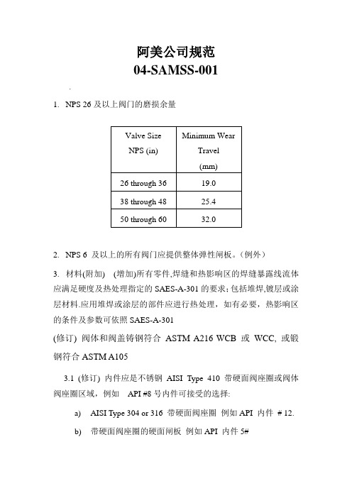
阿美公司规范04-SAMSS-001.1.NPS 26及以上阀门的磨损余量2.NPS 6 及以上的所有阀门应提供整体弹性闸板。
(例外)3.材料(附加) (增加)所有零件,焊缝和热影响区的焊缝暴露线流体应满足硬度及热处理指定的SAES-A-301的要求;包括堆焊,镀层或涂层材料.应用堆焊或涂层的部件应进行热处理,如有必要,热影响区的条件及参数可依照SAES-A-301(修订) 阀体和阀盖铸钢符合ASTM A216 WCB 或WCC, 或锻钢符合ASTM A1053.1(修订) 内件应是不锈钢AISI Type 410 带硬面阀座圈或阀体阀座圈区域,例如API #8号内件可接受的选择:a)AISI Type 304 or 316 带硬面阀座圈例如API 内件# 12.b)带硬面阀座圈的硬面闸板例如API 内件5#4.低温介质(-45 to -18°C)4.1内件须为不锈钢AISI Type 304 或316. 阀座圈须为硬面加司太立#6或等同(API STD 600 内件# 12).5.填料(附加)5.1 碳氢化合物介质下阀杆填料应是由含碳99% 的端环(John Crane - 1625G 或等同)和石墨中间环(John Crane - 237 或等同) 两种编织石墨丝组成的混合填料6.-101 to -45°C超低温介质(附加–仅指定时适用)6.1-101 to -45°C超低温介质阀门的附加a) 阀门应完全由不锈钢AISI Type 304 或316制造. 阀座圈须为硬面加司太立#6或等同(API STD 600 内件# 12).b) 体盖螺栓连接, 压盖螺栓, 压盖螺栓定位器及阀盖到支架的螺栓连接应为奥氏体不锈钢ASTM A320系列. 相应的螺母应为ASTM A194 8级系列c) (附加) 碳氢化合物介质下阀杆填料应是由含碳99% 的端环(John Crane - 1625G 或等同)和石墨中间环(John Crane - 237 或等同) 两种编织石墨丝组成的混合填料d) 泄压关闭零件的回流边上需钻3-5 mm的小孔. 阀体上应清晰标记流向.e) 泄压关闭零件的回流边上需钻3-5 mm的小孔. 阀体上应清晰标记流向.04-SAMSS-0351.水线要求1.1钢制光滑式密封面法兰垫片的接触面全,需要机械光面精整, 完成射程3.2到6.4微米2.排水管,通风口和阀体其他配件(钢阀)2.1 所有排泄阀门及相关管道零件抗耐腐蚀至少相当于内件材料,最低标准为AISI 316L SS3.材质3.1 当对焊连接阀门用碳钢和最低屈服强度289 MPa (42,000psi)或更高,最高碳含量不得超过0.26%.对于编织阀门,这种限制仅适用于端口。
沙特阿美工程规程SAEP-22 Tank Calibration Requirements
Previous Issue: 28 April 2009 Next Planned Update: 22 May 2016Revised paragraphs are indicated in the right marginPage 1 of 15Primary contact: Maatoug, Maatoug A on 966-3- 8747960Engineering ProcedureSAEP-2222 May 2011Tank Calibration RequirementsDocument Responsibility: Custody Measurement Standards CommitteeSaudi Aramco DeskTop StandardsTable of Contents1 Scope............................................................2 2 Conflicts and Deviations................................ 23 Applicable Documents................................... 24 Definitions and Acronyms.............................. 35 Instructions.................................................... 56 Responsibilities.............................................. 87 Activity Matrix.............................................. 10 Attachment I – Required Information on the Tank Capacity Table................. 12 Attachment II – Qualifications of theThird Party Inspection Agency (15)Next Planned Update: 22 May 2016 Tank Calibration Requirements 1 ScopeThis procedure establishes the instructions and responsibilities for the calibration ofall Saudi Aramco royalty/custody tank gauging applications. This procedure is alsoapplicable to the inventory tanks that have the potential to be used for custody orroyalty measurement applications in case of the metering system failures. Organizations for which responsibilities are specified include, but are not limited to:∙The Proponent Organization∙Saudi Aramco Project Management Team (SAPMT)∙Process & Control Systems Department (P&CSD)2 Conflicts and Deviations2.1 Any conflicts between this procedure and other applicable Saudi AramcoEngineering Standards (SAESs), Materials System Specifications (SAMSSs),Standard Drawings (SASDs), or industry standards, codes, and forms shall beresolved in writing by the Manager, Process & Control Systems Department ofSaudi Aramco, Dhahran.2.2 Direct all requests to deviate from this procedure in writing in accordance withSAEP-302 to the Manager, Process & Control Systems Department of SaudiAramco, Dhahran.2.3 Direct all requests for interpretation of this procedure in writing to the Chairman,Custody Measurement Standards Committee for resolution. The Chairman,Custody Measurement Standards Committee shall be solely responsible fordetermining whether a proposed request meets the requirements of this procedure.3 Applicable DocumentsThe procedures covered by this document shall comply with the latest edition of thereferences listed below, unless otherwise noted:3.1 Saudi Aramco ReferenceSaudi Aramco Engineering ProcedureSAEP-302Instructions for Obtaining a Waiver of aMandatory Saudi Aramco EngineeringRequirementNext Planned Update: 22 May 2016 Tank Calibration Requirements3.2 Industry Codes and StandardsAmerican Petroleum Institute (API) Manual of Petroleum MeasurementStandards (MPMS)Chapter 2.2A Measurement and Calibration of UprightCylindrical Tanks by the Manual StrappingMethodChapter 2.2B Calibration of Upright Cylindrical Tanks usingthe Optical-Reference Line MethodChapter 2.2C Calibration of Upright Cylindrical Tanks usingthe Optical-Triangulation MethodChapter 2.2D Calibration of Upright Cylindrical Tanks usingthe Internal Electro-optical Distance RangingMethodChapter 2.2E Calibration of Horizontal Cylindrical Tanks-Part 1: Manual MethodsChapter 2.2F Calibration of Horizontal Cylindrical Tanks-Part 2: Internal Electro-Optical Distance-Ranging MethodStandard 2552 Method for Measurement and Calibration ofSpheres and SpheroidsStandard 2555 Liquid Calibration of Tanks4 Definitions and Acronyms4.1 DefinitionsApprove: Review and formal acceptance characterized by the signature of thefinal authorizing individual or organization.Capacity Table: A table often referred to as a tank capacity table or calibrationtable, showing the capacities of or volumes in a tank for various liquid levelsmeasured from the reference gauge point.Critical Zone: The region between initial and complete flotation of a floatingroof.Custody Transfer Measurement: A specialized form of measurement thatprovides quantity and quality information used for the physical and fiscaldocumentation of a change in ownership and/or responsibility of hydrocarboncommodities. This includes measurement of hydrocarbon liquid movementsNext Planned Update: 22 May 2016 Tank Calibration Requirements(deliveries or receipts) between Saudi Aramco and its customers, suppliers, jointventures and transport contractors including VELA ships.Customer: The party that takes ownership or responsibility of a hydrocarboncommodity from Saudi Aramco.Datum plate: A level metal plate located directly under the reference gaugepoint to provide a fixed contact surface from which liquid depth measurementcan be made.Deadwood: Deadwood refers to any object within the tank, including a floatingroof, which displaces liquid and reduces the capacity of the tank; also anypermanent appurtenances on the outside of the tank, such as cleanout boxes ormanholes, which increase the capacity of the tank. Deadwood is positive if itincreases tank capacity or negative if it decreases capacity.External Floating Roof: A cover over an open top storage tank consisting of adeck which rests upon the liquid being contained.Internal Floating Roof: A cover within a fixed roof tank which rests upon thepetroleum liquid being contained.Master Tape: A tape that is used for calibrating working tapes for tankmeasurements and is identified with a report of calibration at 68°F (20°C) and aspecific tension designated by the National Institute of Standards andTechnology (NIST) or an equivalent international standard organization.Recomputation: The process of re-generating the capacity tables through softcalculations, without repeating the field calibration measurements. It involves,simply, updating or revising the capacity table using previously established tankdiametersReference Gauge Height: The distance from the datum plate or tank bottom tothe reference gauge point.Royalty Measurement: A specialized form of measurement that is used as thebasis for paying royalty to the Saudi Arabian Government.SAP: The Saudi Aramco main system for enterprise resource management.Spheres: A stationary liquid storage tank, supported on columns so that theentire tank shall be aboveground.Spheroid: A stationary liquid storage tank having a shell of double curvature.Any horizontal cross-section is a series of circular arcs.Next Planned Update: 22 May 2016 Tank Calibration Requirements Strapping: The measurement of the external circumference of a vertical orhorizontal cylindrical tank by stretching a steel tape around each course of thetank's plates and recording the measurement.Tank Calibration: The process of determining the capacity of a tank throughfield measurements.Third Party Inspection Agency: An independent inspection agency whosefunction is to conduct an unbiased inspection of certain systems, equipment,materials, etc., against a set of standards, guidelines or procedures. For purposesof this SAEP, the Third Party Inspector has particular knowledge of andexperience of conducting tank calibration in accordance with industry custodymeasurement standards and procedures.4.2 AbbreviationsAPI American Petroleum InstituteCMU Custody Measurement Unit of Process & Control SystemsDepartmentEODR Electro Optical Distance RangingORLM Optical Reference Line MethodMPMS Manual of Petroleum Measurement StandardsP&CSD Process & Control Systems DepartmentSA Saudi AramcoSAEP Saudi Aramco Engineering ProcedureSAES Saudi Aramco Engineering StandardSAMSS Saudi Aramco Material SpecificationSAP Systems Application ProgrammingSASD Saudi Aramco Engineering Standard Drawing5 Instructions5.1 GeneralThis procedure shall be used in conjunction with existing international standardsand is not intended to replace the standards referred to in Section 3 above.The reference temperature for all tank capacity tables shall be 60°F forRefineries, Terminals, Gas Plants and 15°C for Distribution Operations.Next Planned Update: 22 May 2016 Tank Calibration Requirements5.2 Calibration/Re-calibration FrequenciesAll new tanks/vessels used for custody transfer measurement must undergocalibration prior to being put in service.All tanks/vessels must be recalibrated in conjunction with Testing andInspection (T&I), or when a major repair is don for tank bottom.The upright cylindrical tank shall be recalibrated in accordance within volume detected to invoke this appendix requirement.5.3 Precalibration PreparationsPrior to calibration, the upright cylindrical tanks, horizontal tanks, spheres andspheroids must have been filled to 95% of their design operating capacity for aminimum period of 24 hours with a liquid at least as dense as the product theywill normally store.Commentary Note:This requirement is considered met if the tank/vessel has been already hydro-tested.5.4 Recomputation RequirementsThe capacity table of horizontal tanks, spheres and spheroids must berecomputed if variation in product operating temperatures and temperatureassumed during calibration is greater than 11°C (20°F).Commentary Note:Variations in the product's calibration specific gravity and operating specificgravity greater than 20% will require a recomputation of the table, due to thehydrostatic head effect expansion on tanks/vessels.Floating roof correction table requires recomputation when any variation in theroof's weight, due to repairs or modifications, results in a change in the roofdeadweight that altered the tank predetermined volume by 0.02% or more.Commentary Note:While recalibration involves reestablishing tank diameters through standardcalibration methods and developing new tank capacity tables for custody andnon-custody transfers, recomputation, involves simply updating or revising thecapacity table using previously established tank diameters.Next Planned Update: 22 May 2016 Tank Calibration Requirements5.5 Acceptable Calibration TechnologiesFollowing is a list of the calibration technologies acceptable for tank/vesselcalibrations along with the reference standard the methods' implementationshould comply to. The methods are arranged in the order of priority, based onthe most efficient means of calibration for a given set of conditions.(1) Internal Electro Optical Distance Ranging Method (EODR),API Chapter 2.2D(2) Internal Electro Optical Distance Ranging Method (EODR),API Chapter 2.2F(3) Optical Reference Line Method (ORLM), API Chapter 2.2B(4) Manual Strapping Method(Strapping), API Chapter 2.2A(5) Optical Triangulation Method, API Chapter 2.2C(6) Manual Methods, API Chapter 2.2E(7) Liquid Calibration, API 2555(8) Method for Measurement and Calibration of Spheres and Spheroids,API STD 2552Commentary Note:All these methods essentially provide alternate techniques for measuring tankdiameters. While manual strapping is limited to external calibrations, theremaining methods can be used either externally or internally.5.6 Technology Selection Guidelinesa. The application of the EODR shall be limited to tanks/vessels that aregreater than 5 meters in diameter.b. The application of liquid calibration shall be limited to tanks/vessels thatare smaller than 5 meters in diameter.c. If a tank/vessel is insulated, it should be calibrated internally.d. External and internal EODR shall be used for all tanks/vessels that aregreater than 5 meters in diameter with no insulation.e. Either Internal or external ORLM shall be used for floating roof tanks.f. External ORLM can be used for fixed roof tanks with no insulation andhaving not more than a single wind girder.g. If the tank has multiple external wind girders, it should be calibrated eitherby external/internal EODR or internal ORLM.Next Planned Update: 22 May 2016 Tank Calibration Requirementsh.bottom elevations shall be sighted along radii every 45 degrees. Alongthese radii, elevations should be obtained at equally spaced intervals notmore than 10 feet (3 meters) from the tank's center to its shell. Liquidcalibration method is permitted to be used whenever the tank containsirregular shaped deadwood (e.g., steam coils, etc.).i. Spheres and spheroids shall be calibrated in accordance with API STD2552, Method for Measurement and Calibration of Spheres and Spheroids.6 ResponsibilitiesThe Saudi Aramco organizations with tank/vessels calibration responsibilities shallensure that their personnel become familiar with this SAEP.6.1 Saudi Aramco Project Management Team (SAPMT)a. Initiate calibration request for new tanks/vessels,b. Inform CMU of the calibration of new tanks only if is used for royaltytransfer,c. Request list of Approved Third Party Inspection Agencies,d. Contract tank calibrations to an approved Third Party Inspection Agency,e. Inform the Proponent to witness the calibration process,f. Obtain the capacity tables from the Third Party Inspection Agency,g. Request CMU's review for capacity tables of new royalty tanks,h. Provide two hardcopy and two electronic tables in US Customary unitsand/or (based on application requirement) SI units of the final approvedcalibration calculation and the capacity table to the Proponent.i. Close the activity.6.2 The Proponent Organizationa. Initiate requests for in-service tanks/vessels per the frequencyrequirements set forth in Section 5.2 above,b. Inform CMU of the calibration of new tanks if it is used for royaltytransfer applications,c. Request list of the approved Third Party Inspection Agencies,d. Contract tank calibrations to an approved Third Party Inspection Agency,e. Provide the operating data (operating temperature, density at operatingtemperature, operating pressure) to the Third Party Inspection Agency,Next Planned Update: 22 May 2016 Tank Calibration Requirementsf. Ensure the equipment used has been calibrated and has valid certificatesthat are traceable to National Institute of Standard and Technology (NIST)or other approved standards organization,g. Witness the field calibration process and ensure that the Third PartyInspection Agency is performing the tank/vessel calibration calculations inaccordance API MPMS Chapter 2.2A and API STD 2552, including, butnot limited to, the following capacity table correction factors,i. master tape corrections.ii. working tape correction.iii. tape rise correction.iv. tank shell temperature expansion correction.v. hydrostatic head effect correction.vi. tilt correction.vii. floating roof gravity adjustment.h. Consult with CMU if a technical inquiry about the calibration and/ordocumentation process cannot be resolved internally,i. Review the draft calibration calculations,j. Review the produced capacity tables and make sure they comply with the requirements in Attachment I,k. Submit the capacity tables for the calibration of the new tanks to theSAPMT,l. Submit initial capacity tables of new royalty tanks only to CMU forreview.m. Maintain two hardcopy and two electronic tables in US Customary units and/or (based on application requirement) SI units of the final approvedcalibration calculation and the capacity table to the proponent,n. Update the SAP Tank Gauging System with the new approved capacitytable, if applicable,o. Inform the SAPMT of the completion of the tank calibration,p. Commission the tank,q. Close the activity.6.3 Process & Control Systems Department (P&CSD)The Process & Control Systems Department/Custody Measurement Unit (CMU)is responsible for providing technical assistance to the Proponent(s) on mattersNext Planned Update: 22 May 2016 Tank Calibration Requirements pertaining to tank calibrations. Specific responsibilities of CMU aresummarized below:a. Review the qualifications of the Third Party Inspection Agencies and makesure they meet all of the requirements detailed in Attachment II.b. Maintain the list of Approved Third Party Inspection Agencies.c. Submit the list of the Approved Third Party Inspection Agencies to theSAPMT and the Proponent upon request.d. Upon request from the proponent, provide consultation if a technicalinquiry about the calibration and/or documentation process cannot beresolved internally.e. Review initial capacity tables of new royalty tanks only.7 Activity MatrixThe following matrix summarizes the general sequence of activities and corresponding responsible organizations for calibrating tanks. Detailed requirements for eachorganization are specified in Section 6.Next Planned Update: 22 May 2016 Tank Calibration RequirementsNote:(1) SAPMT initiates calibration request for new tanks/vessels. The Proponent initiates calibrationrequest for tanks/vessels in-service per the frequency requirements set forth in Section 5 above.For BI-1900, the proponent will assume the responsibilities of SAPMT.Revision Summary22 May 2011 Revised the "Next Planned Update". Reaffirmed the contents of the document, and reissuedwith minor changes.Next Planned Update: 22 May 2016 Tank Calibration Requirements Attachment I – Required Information on the Tank Capacity TableThe final capacity table should contain the following minimum documentation details:1. Tank Identificationa. The site or installation tank numberb. Location Titled with “Saudi Arabian Oil Company”c. The type of tank in serviced. The name of the plant, owner or operatore. The name and address of the calibration authority or company which carriedout the calibration.2. Product InformationThe product name and density of the liquid stored in the tank when in service andused in the computation of the tank capacity tables.3. Operational Detailsa. The standard temperature (60°F for U.S. Customary, or 15°C for metrictables) for which the tank capacity table has been calculated.b. Operating temperature and pressurec. Table type (innage or ullage)4. Traceability and Tracking Detailsa. The date a new tank was first calibratedb. The date an old tank was recalibratedc. Calibration agent reference document numberd. The date the tank was recomputed, and the method used for recomputatione. The date of the calibration along with specific references to the methodadopted in calibrating the tank bottomf. Page numberg. Reference to the standard on which the calibration is basedh. The Third Party Inspection Agency shall sign and stamp each page of thecertificate.Next Planned Update: 22 May 2016 Tank Calibration Requirements5. Tank Dimensionsa. The nominal height and diameter of the tankb. Description of the tank bottom type, along with the method used todetermine the bottom volumec. Integrated deadwood, accurately accounted for as to location and volume,and included as an attachmentd. Note on capacity table that the volume below the striking plate is included inthe first measuremente. The shell height, is measured as the vertical distance between the bottom ofthe bottom angle and top of the top angle and measured near the referencegauge hatchf. Reference height measurement point locations shall be clearly identified ontank capacity tablesg. The height of the datum-points(s) with reference to the junction of the tankshell and bottom platingh. If an automatic gauging system is installed, the height of the gauge datumpoint with reference to the junction of the tank shell and bottom platingi. Maximum fill heightj. Safe fill height specified by the tank ownerk. The amount of tilt in shell height is measured and recorded.l. Height of the striking point (datum plate) from the tank bottom platem. The decimal (fraction) average volume for each strapping page.6. Floating Roof Informationa. The allowance for the roof is to be treated as deadwood and incorporated inthe tank capacity table directly, not as a separate attachmentb. The density of the liquid for which the roof has been calculated shall berecorded on the table directlyc. The apparent mass in air of the roof and accessoriesd. The displacement volume of the roof and the floating roof correction factormethod statemente. A defined level (Level A), with the distance above the dip point designatingwhere the roof is at restf. A defined level (Level B), with the distance when the roof is just fullyfloating in the lowest-density liquid to be contained in the tankNext Planned Update: 22 May 2016 Tank Calibration Requirementsg. The part of the capacity table between Level A and Level B is marked as“Not Accurate”h. Critical zones shall be identified within the tablei. The range where floating roof adjustment not to be performed.7. Tank Shell Correctiona. A shell temperature expansion factor table is to be developed in incrementsof 5°F or 3°C and included as an attachment to the capacity table for aspecific operating range.b. Include the equation for determining the shell temperature.Next Planned Update: 22 May 2016 Tank Calibration Requirements Attachment II – Qualifications of the Third Party Inspection AgencyThe Third Party Inspection Agency shall meet all of the following requirements:1. The agency has provided similar services for a minimum of 3 years. It shallsubmit a list of companies for which it has provided similar calibration servicesover the preceding 3 years.2. The agency's personnel performing the field measurements and calculations musthave a minimum of one year experience with the application of the APItank/vessel calibration standards. Experience shall be documented by submittal ofresume and verifiable work histories.3. The agency shall have written procedures which meet the requirements of APItank/vessel calibration standards. It shall submit the written procedures forreview.4. The agency shall have equipment as specified in API MPMS Chapter 2.2. It shallsubmit a list of the equipment it intends to use along with corresponding validcalibration certificates.5. The agency shall demonstrate it is ISO-certified and that it is activelyadministering a quality assurance program. It shall submit a copy of its ISOcertification and his quality assurance program details for review.6. The agency shall demonstrate that it is capable of performing the tank/vesselcalibration calculations. It shall provide a minimum of two samples of previouscalibration results, including field data and all calculations.7. The agency shall provide financial and insurance documentations as deemednecessary by the Contracting Unit to ensure he has adequate liability coverage fordamages done to Saudi Aramco facilities.。
SAEP-352 Welding Procedures Review and Approval
Previous Issue: 31 May 2003 Next Planned Update: 20 October 2014Page 1 of 14Primary contact: Al-Sabti Tareq Ibrahim on 966-3-8760236Engineering ProcedureSAEP-35220 October 2009Welding Procedures Review and Approval Welding Standards Committee MembersAwwami, Adnan Ni'Mah, Chairman Rao, Sanyasi, Vice Chairman Carrera, R LCarswell, Raymond J. Juraifani, Hatim Hamad Keen, Peter DavidMuslim, Husain Muhammad Nasri, Nadhir Ibrahim Niemeyer, Dennis Charles Sabti, Tareq IbrahimSayed Nasir, Ghalib TaherSaudi Aramco DeskTop StandardsTable of Contents1 Scope.............................................................2 2 Conflicts and Deviations................................. 23 Applicable Documents.................................... 24 Definitions and Acronyms............................... 6 5Instructions and Approval Responsibility (7)Table 1 – Welding Procedure Technical Approval Responsibility………..……….. 9 Appendix I – Welding Master Set Preparation and Approval..................... 12 Appendix II – Welding Package Review and Approval Process for Company Projects................................ 13 Appendix III – Welding Package Review and Approval Process forRepair/Maintenance/Alterations (14)Next Planned Update: 20 October 2014 Welding Procedures Review and Approval1 Scope1.1 This procedure specifies the responsibilities for welding procedure review andapproval. This procedure applies to pressure vessels, process equipment orcomponents, piping, pipelines, and structures fabricated to a variety ofstandards, such as but not limited to ASME SEC I, IV, VIII, B31.1, B31.3,B31.4, B31.8 and API STD 560, 620 and 650, and AWS D1.1.1.2 Additional requirements may be contained in Scopes of Work, Drawings, orother Instructions or Specifications pertaining to specific items of work.2 Conflicts and DeviationsConflicts between this Engineering Procedure and any other Saudi Aramco Standardshall be resolved by the Consulting Services Department in writing.3 Applicable DocumentsUnless stated otherwise, all Standards, Specifications, and Codes referenced in thisprocedure shall be of the latest issue (including revisions, addenda, and supplements)and are considered a part of this procedure.3.1 Saudi Aramco ReferencesSaudi Aramco Engineering ProcedureSAEP-310Piping and Pipeline RepairSaudi Aramco Engineering StandardsSAES-D-008Repairs, Alterations, and Rerating of PressuredEquipmentSAES-D-108Storage Tank IntegritySAES-D-116Underground Storage Tank SystemSAES-K-001Heating, Ventilating and Air Conditioning (HVAC)SAES-L-350Construction Requirements for Metallic PlantPipingSAES-L-450Construction Requirements for Cross-CountryPipelinesSAES-L-460Pipelines Crossing Under Roads and RailroadsSAES-L-850Design of Submarine Pipelines and RisersNext Planned Update: 20 October 2014 Welding Procedures Review and Approval SAES-M-001Structural Design Criteria for Non-BuildingStructuresSAES-M-005Design and Construction of Fixed OffshorePlatformsSAES-M-009Design Criteria for Blast Resistant BuildingsSAES-T-744Design Criteria/Installation of CommunicationTowersSAES-W-010Welding Requirements for Pressure VesselsSAES-W-011Welding Requirements for On-Plot PipingSAES-W-012Welding Requirements for PipelinesSAES-W-013Welding Requirements for Offshore StructuresSAES-W-014Weld Overlays and Welding of Clad MaterialsSAES-W-015Strip Lining ApplicationSAES-W-016Welding of Special Corrosion-Resistant MaterialsSAES-W-017Welding Requirements for API TanksSaudi Aramco Materials System Specifications01-SAMSS-010Fabricated Carbon Steel Piping01-SAMSS-017Auxiliary Piping for Mechanical Equipment01-SAMSS-035API Line Pipe01-SAMSS-038Small Direct Charge Purchases of Pipe01-SAMSS-046Stainless Steel Pipe01-SAMSS-333High Frequency Welded Line Pipe02-SAMSS-001Piping Components for Low Temperature Services02-SAMSS-005Butt Welding Pipe Fittings02-SAMSS-006Hot Tap and Stopple Fittings02-SAMSS-008Insulating Joints/Spools for Cathodic Protection02-SAMSS-009Design and Fabrication of Scraper Traps02-SAMSS-010Flanged Insulating Joints/Spools for CathodicProtection02-SAMSS-011Forged Steel Weld Neck Flanges for Low,Intermediate and High Temperature Service 04-SAMSS-035General Requirements for ValvesNext Planned Update: 20 October 2014 Welding Procedures Review and Approval 04-SAMSS-053Steel Lubricated Plug Valves - Flanged andWelding End12-SAMSS-007Fabrication of Structural and Miscellaneous Steel12-SAMSS-014Pre-Engineered Metal Building27-SAMSS-001Packaged Water Cooled Centrifugal Chillers forUtility Services27-SAMSS-002Direct Expansion Air Conditioning Systems forOffshore Facilities27-SAMSS-003Manufacture of Non-Industrial Cooling Towers30-SAMSS-001Diesel Engines31-SAMSS-001Centrifugal Compressor31-SAMSS-002Packaged Reciprocating Plant and Instrument AirCompressors31-SAMSS-003Reciprocating Compressors for Process Air orGas Service31-SAMSS-004Centrifugal Pumps31-SAMSS-005Centrifugal Fluorocarbon Refrigeration Units forIndustrial/Process Services31-SAMSS-006Packaged, Integrally Geared Centrifugal AirCompressors31-SAMSS-009Positive Displacement Pumps - Controlled Volume31-SAMSS-010Submersible Pumps and Motors for Water Welland Offshore Service31-SAMSS-012Shaft Sealing Systems for Centrifugal and RotaryPumps32-SAMSS-001Special Purpose Steam Turbines for Generator Sets32-SAMSS-004Manufacture of Pressure Vessels32-SAMSS-005Manufacture of Atmospheric Tanks32-SAMSS-006Manufacture of Low Pressure Tanks32-SAMSS-007Manufacture of Shell and Tube Heat Exchangers32-SAMSS-008Inlet Air Filtration Systems for Combustion GasTurbines32-SAMSS-009General Purpose Steam Turbines32-SAMSS-010Special Purpose Steam TurbinesNext Planned Update: 20 October 2014 Welding Procedures Review and Approval32-SAMSS-011Manufacture of Air-cooled Heat Exchangers32-SAMSS-013Lubrication, Shaft Sealing and Control Oil Systems32-SAMSS-016Inlet Air Filtration Systems for Centrifugal AirCompressors32-SAMSS-017Side-Entry Mixers32-SAMSS-019Manufacture of Plate and Frame Heat Exchangers32-SAMSS-020Manufacture of Trays and Packing32-SAMSS-021Manufacture of Industrial Boilers32-SAMSS-022Manufacture of Components for Flare Systems32-SAMSS-027Manufacture of Electric Heat Exchangers32-SAMSS-028Manufacture of Double Pipe Heat Exchangers32-SAMSS-029Manufacture of Fire Heaters32-SAMSS-030Manufacture of Small Tanks32-SAMSS-031Manufacture of Clad Vessels and Exchangers32-SAMSS-033Reverse Osmosis Systems32-SAMSS-035Manufacture of Heat Recovery Steam Generator32-SAMSS-036Manufacture of Small Pressure Vessels32-SAMSS-100Combustion Gas Turbines34-SAMSS-611Safety Relief Valves Conventional and BalancedTypes34-SAMSS-612Safety Relief Valves Pilot Operated Types34-SAMSS-711Control Valves45-SAMSS-005Valves and Wellhead Equipment Requirements perAPI SPEC 6A3.2 Industry Codes and StandardsAmerican Petroleum InstituteAPI STD 560Fired Heaters for General Refinery ServicesAPI STD 620Design and Construction of Large, Welded, Low-Pressure Storage TanksAPI STD 650Welded Steel Tanks for Oil StorageAPI STD 1104Welding of Pipelines and Related FacilitiesNext Planned Update: 20 October 2014 Welding Procedures Review and ApprovalAmerican Society of Mechanical EngineersASME B31.1Power PipingASME B31.3Process PipingASME B31.4Pipeline Transportation Systems for LiquidHydrocarbons and other LiquidsASME B31.8Gas Transmission and Distribution PipingSystemsASME SEC I Rules for Construction of Power BoilersASME SEC IV Rules for Construction of Heating BoilersASME SEC VIII Rules for Construction of Pressure VesselsASME SEC IX Welding and Brazing QualificationsAmerican Welding SocietyAWS D1.1Structural Welding Code-Steel4 Definitions and AcronymsApplication Approval: Approval acquired from Inspection Department to applytechnically approved welding procedure. ID generally verifies that the intendedapplication of previously approved welding procedures is within the weldingprocedure's variables (e.g., diameter, thickness, materials, service, etc.) approval range.CSD: Consulting Services Department Welding Specialist/Engineer or CSD'sAppointed Representative (e.g., Aramco Services Company WeldingSpecialist/Engineer).ID: Inspection Department Vendor, Operations or Project Inspector or InspectionRepresentative.PMC: A Program Management Contractor.SAPMT: Saudi Aramco Project Management Team or someone acting on their behalf such as PMC.PMT Designated Welding Representative (PMT DWR): A welding engineer /inspector assigned to and contracted by SAPMT who has the approval authority forproject(s) associated welding procedures.PQR: Performance Qualification RecordNext Planned Update: 20 October 2014 Welding Procedures Review and Approval Technical Approval: Approval of welding procedures acquired from CSD or PMTDesignated Welding Representative. This approval indicates that the weldingprocedure was qualified to Saudi Aramco and/or industry standards or codes and it isacceptable for the intended application. Every page of the welding procedurespecifications should include the reviewer signature and/or approval stamp.Weld and Line Designation Table: A table that lists the applicable weldingprocedures, approval conditions (e.g., low temperature, sour service, etc.), weldingprocess, and any general welding information pertinent to those applicable weldingprocedures.Weld Map: A schematic one line diagram of pressure containing equipment (e.g.,pressure vessel or tank). The map should indicate where each approved weldingprocedure will be applied.Welding Master Set (WMS): It is compilation of welding procedures prepared byvendor/fabricator. It is a standardized set of welding procedures that is used with ageneric Weld and Line Designation Table and/or generic Weld Map, which include the material and service application information.WP: Welding Package.WPS: Welding Procedure Specifications.5 Instructions and Approval Responsibility5.1 CSD shall be the technical approval authority for the followings:a) All Saudi Aramco Project welding procedures for applications listed inTable 1 from either in-kingdom or out of kingdom fabricators andconstruction contractors. Appendix II is a flowchart that indicates thereview process for Saudi Aramco projects.b) "Welding Master Set" submissions for the applications listed in Table 1from in-Kingdom and Gulf Cooperation Council fabricators. SeeAppendix I for details on welding master set's preparation and approval.Appendix II is a flowchart that indicates the review process for SaudiAramco projects. The Welding Master Set (WMS) is submitted to PMTfor CSD's one-time technical approval. When WMS is approved by CSDthen it can be often used in various Saudi Aramco projects if ID approvesthe application.c) Maintenance/repair/alteration applications. Appendix III is a flow chartthat indicates the review process.Next Planned Update: 20 October 2014 Welding Procedures Review and Approval5.2 A PMT designated welding representative assigned to and contracted bySAPMT may be the approval authority for project(s) associated weldingprocedures. He must review the welding procedures for all applications listed inTable 1, and as requested by PMTCSD will interview and approve the PMT designated welding representative.Written examinations may be requested and prepared by CSD, this will dependon the project scope. With coordination with SAPMT, CSD will periodicallyaudit some of his welding procedures review.5.3 For applications not listed or not requiring CSD/PMT DWR review in Table 1the qualified welding procedures shall be available at the fabrication/weldingsite (e.g., vendor shop, field fabrication, etc.) for review by the Inspector, ifrequested. The procedures shall be included in the project or shopdocumentation record books.5.4 If the welding procedure is approved to the latest edition of the weldingstandards, then the fabricator/construction contractor is permitted to use thewelding procedure without CSD/PMT DWR review. The assigned inspectormust verify that the qualification range (e.g., diameter, thickness, material grade,etc.) of the welding procedure is still applicable to the new work.5.5 If the welding procedure is approved to a previous edition of the weldingstandards, then fabricator/construction contractor is permitted to use it, if it wasnot affected by the revisions. The fabricator/construction contractor must writea formal letter to PMT or Engineering/Maintenance Div. indicating that thesubject welding procedure still complies with the latest edition of Saudi AramcoWelding Standards. The assigned inspector must verify that the qualificationrange (e.g., diameter, thickness, material grade, etc.) of the welding procedure isstill applicable to the new work.5.6 If the previously approved welding procedure is invalidated by a change in thewelding standard, a revised welding procedure, along with the old approvedcopy, must be submitted for CSD/PMT DWR review. The assigned inspectormust verify that the qualification range (e.g., diameter, thickness, material grade,etc.) of the welding procedure is still applicable to the new work.Revision Summary20 October 2009 Major revision.Next Planned Update: 20 October 2014 Welding Procedures Review and Approval Table 1 – Welding Procedure Technical Approval ResponsibilityNext Planned Update: 20 October 2014 Welding Procedures Review and Approval Table 1 – Welding Procedure Technical Approval Responsibility (cont'd)Next Planned Update: 20 October 2014 Welding Procedures Review and Approval Table 1 – Welding Procedure Technical Approval Responsibility (cont'd)Notes:1. Formal approval is not required. However, all WPS/PQR/Weld Map documents must be available for the inspectorreview or verification upon his request.2. In special cases the PMT or the Engineering/Maintenance Division may request CSD procedure review for anyapplication. This may be done even though procedure review is not required according to Table 1 or is not listed inTable 1.Next Planned Update: 20 October 2014 Welding Procedures Review and ApprovalAppendix I – Welding Master Set Preparation and Approval1. Each fabricator/vendor awarded a contract or purchase order will compile all CSDrevised previously approved welding procedures and any welding procedures,intended to be used in Saudi Aramco projects.2. Revised previously approved welding procedures must be submitted in new forms,unsigned, and the approved copy is attached to compare welding parametersbetween the two copies.3. The master set must include typical "Weld Maps", "Weld Description" sheet,"Request for Welding Procedure Approval" form and any supporting documentrequired to be submitted by Saudi Aramco Welding Standard (SAES-W-010,SAES-W-011, etc.). It is recommended that a distinct identification system isused for the WPS and the revision number (e.g., WPS # is WMS P1-P8-1 and therevision # is M0, here both WMS and M indicate that the welding procedure ispart of welding master set).4. The PQRs must be either the originals, certified/stamped copies, or colored copiesof the originals. The qualification tests must be performed by independent testingagency approved by Saudi Aramco (Contact CSD Welding Group to get theupdated list of the approved independent test agencies).5. The time required to review each master set will depend on the number of thesubmitted welding procedures and the pertinent technical welding requirements(e.g., PWHT, hardness test, impact toughness test, etc.). The table below lists theestimated time to review welding master sets.Estimated Time to Review Welding Master Sets6. After the initial technical approval, the welding procedures can be applied invarious company projects if ID approves the application.7. The fabricator/ Construction Contractor must continuously review the approvedwelding procedures to ensure their conformance with the latest applicable SaudiAramco Welding Standards and Industry Codes.Next Planned Update: 20 October 2014 Welding Procedures Review and Approval Appendix II – Welding Package Review andApproval Process for Company ProjectsNext Planned Update: 20 October 2014 Welding Procedures Review and Approval Appendix III – Welding Package Review andApproval Process for Repair/Maintenance/Alterations。
阿美规范注意的方面(1)
从质量管理来讲,沙特项目与国内项目的主要差异在于:业主和承包商在施工过程中,对规范的理解、要求以及执行力上存有很大差异。
现将阿美规范中,需要施工方和承包商注意的事项罗列出来,这些事项都是在哈维亚项目在施工过程中,遇到的棘手问题,TR和SINOPEC解决起来,耗时耗力,对工期和费用影响比较大。
1.相邻两对焊口间距:应为20mm或不低于3倍的母材壁厚,两者取大值。
详见SAES-W-011 para 11.16Weld encroachment and minimum distance between welds.The requirements for minimum separation between adjacent welds are listed in11.16.1 and 11.16.2. The distances shall be measured between the edges of theadjacent cap passes. These restrictions do not apply if one of the welds has been postweld heat treated prior to making the second weld or both welds have been postweld heat treated and inspected.11.16.1 The minimum distance between parallel butt welds shall be 20 mm orthree times the wall thickness of the joint, whichever is greater.2.不得在配件上开孔。
详见SAES-L-110 para 12.3,Branch connections, such as those for drain and vent connections, on tees, elbows and reducers are not permitted. When not avoidable, the piping design shall be reviewed and approved by the Chairman of Piping Standards Committee.3.支管补强板要求,及附表规定不同管材(支管)与主管连接形式(凸台、护板及三通)。
- 1、下载文档前请自行甄别文档内容的完整性,平台不提供额外的编辑、内容补充、找答案等附加服务。
- 2、"仅部分预览"的文档,不可在线预览部分如存在完整性等问题,可反馈申请退款(可完整预览的文档不适用该条件!)。
- 3、如文档侵犯您的权益,请联系客服反馈,我们会尽快为您处理(人工客服工作时间:9:00-18:30)。
Previous Issue: 15 October 2008 Next Planned Update: 15 October 2013Revised paragraphs are indicated in the right marginPage 1 of 5 Primary contact: Ghulam, Ziad Mohammad Jamil on 966-3-8745670Engineering ProcedureSAEP-134 4 March 2009 Preparation of Saudi Aramco Engineering ProceduresDocument Responsibility: Standards CoordinatorSaudi Aramco DeskTop StandardsTable of Contents1 Scope (2)2 Applicable Documents (2)3 Instructions (2)4 Responsibilities (4)Next Planned Update: 15 October 2013 Preparation of Saudi Aramco Engineering Procedures1 ScopeSaudi Aramco Engineering Procedures (SAEPs) establish instructions andresponsibilities associated with various engineering activities. This document contains the instructions to initiate, format, prepare, revise, coordinate and obtain approvals forall SAEPs.SAEPs are procedures, approved by Saudi Aramco Management, that establishminimum requirements for dealing with their associated subject material. They aremandatory and apply on a Company-wide basis.2 Applicable DocumentsThe requirements contained in the following documents apply to the extent specified in this procedure:Saudi Aramco Engineering ProceduresSAEP-301 Instructions for Establishing and MaintainingMandatory Saudi Aramco EngineeringRequirementsSAEP-302 Instructions for Obtaining a Waiver of a MandatorySaudi Aramco Engineering Requirement3 Instructions3.1 PurposeThe purpose of a SAEP is to establish and approve a systematic method orprocess of accomplishing an engineering related activity.3.2 Organization and Contents3.2.1 The content of each SAEP is to be divided and the material organizedinto a minimum of four mandatory sections:∙Scope: This section of the procedure is normally used to describe thesubject matter of the document, including the extent of itsapplication. It can also make an overall general statementencompassing the content or functional intent of the SAEP.∙Applicable Documents: This section lists all documents that arereferenced within the procedure. Do not list documents that are notreferred to.Next Planned Update: 15 October 2013 Preparation of Saudi Aramco Engineering Procedures ∙Instructions: This section provides the procedure's instructions orguidelines to be followed.∙Responsibilities: This section establishes the responsibilities,authority and approvals associated with carrying out the procedure'sinstructions.3.2.2 Additional sections may be included as necessary, depending upon thesubject matter involved. Add more sections only when it is necessary toinclude material that does not logically fit within one of the mandatorysections.3.2.3 Appendices may be included to provide information in support of themain text of the SAEP. This may include tables, charts, graphs,examples, etc. Do not include Saudi Aramco forms in the procedure.Instead, make reference to them by their form number.Identify appendices as Appendix A, B, etc., on consecutively numberedpages. Locate appendices after the last page of the last SAEP sectionand list each appendix in the Table of Contents.3.3 Deviation from Procedure RequirementsApproval to deviate from the requirements given in a SAEP shall be obtained byfollowing the waiver instructions of SAEP-302.3.4 Cancellation of SAEPCancel existing SAEPs by obtaining the signature of the procedure's ApprovalAuthority.3.5 Document NumberingDocument numbers will be assigned to SAEPs based on the following:∙Two digit numbers: Approval by Senior Vice President∙Three digit numbers: Approval by Vice President or Chief Engineer∙Four digit numbers: Approval by Department ManagerThe mechanism of determining the document number of an engineeringprocedure will be based on the safety, cost, and maintenance and operationsimpact of the procedure. It will be supported and based on the followingfundamental nature:a) If the procedure will be utilized solely by the Saudi Aramco ResponsibleNext Planned Update: 15 October 2013 Preparation of Saudi Aramco Engineering ProceduresOrganization (who develops the procedure), a four digit number will beassigned and approval shall be by the Department Manager.b) If the procedure will be utilized by other department(s) within the sameadmin. area aside from the SARO, a three digit number will be assignedand the approval shall be by the Vice President or Chief Engineer.c) If the document will be utilized by other department(s) belonging to otherbusiness line(s), a two digit number will be assigned and the approval shallbe by the Sr. Vice President of the proponent organization.Commentary Note:The Saudi Aramco Responsible Organization (SARO) should evaluate the costimplication as a result of developing a two-digit procedure.4 Responsibilities4.1 Saudi Aramco Responsible Organization (SARO)The SARO is the department responsible for the procedure. All SAEPs musthave an assigned SARO. Specific responsibilities of the SARO include:∙Determine the need for new SAEPs, and review existing SAEPs, at least once every five (5) years per SAEP-301, to determine if they are still valid.Where required, revise procedures to achieve broadest company-wideapplication, maintain overall cost-effectiveness, ensure technical adequacy,and generally keep them up-to-date.∙Determine the approval authority for the procedure.∙Determine if company-wide input is needed for procedures containing major revisions or new SAEPs.∙Forward draft documents to the Standards Coordinator to either route for BOE review or for the completion of approval, publication, and distributionprocesses per SAEP-301 paragraph 4.7(g).∙Forward all original approval copies of procedures to the StandardsCoordinator for historical filing. Include other documents judged importantenough to be kept with the document file.4.2 Board of Engineers (BOE)∙Review SAEPs as required by paragraph 4.1, ensuring they are acceptable from the technical, safety, economic and implementation standpoint.Next Planned Update: 15 October 2013 Preparation of Saudi Aramco Engineering Procedures ∙Recommend to the Approval Authority, appropriate changes to achieve an optimum balance of technical, safety, economic and implementation factors.4.3 Approval AuthorityThe Approval Authority, determined by the SARO for each procedure, shallreview each procedure to ensure that the final procedure should be approved foruse. For documents reviewed by the BOE, ensure that all major comments havebeen resolved.4.4 Standards CoordinatorThe Standards Coordinator is responsible for the administration of all SAEPs.Specific responsibilities include:∙Maintain accurate records of all approved SAEPs, including issue dates and next planned revisions. Keep historical files and copies of all SAEPs,including original document approval signatures.∙Assign document numbers to new SAEPs.∙Establish document format and content requirements. Review all SAEPs prior to final approval for conformance to these requirements.∙Forward draft SAEPs to the BOE for review, and final revised SAEPs to the document's Approval Authority.∙Approve minor editorial changes to the procedure for such things astypographical errors, organization name and title changes approved byManagement, and reference document name changes.∙Disseminate the information of all approved SAEPs per SAEP-301paragraph 4.7(g).∙Notify SARO representatives of approaching planned revision dates insufficient time to allow an orderly review and rewrite of the procedure, ifrequired.Revision Summary15 October 2008 Revised the "Next Planned Update." Reaffirmed the contents of the document, andreissued with editorial changes.4 March 2009 Editorial revision to clarify Section 3.5 (Document Numbering).。