沙特阿美工程规程SAEP-22 Tank Calibration Requirements
沙特阿美工程规程SAEP-1109 Welding Test Supplement S09 for GTAW, Aluminum, Single Sided

Engineering ProcedureSAEP-1109 6 June 2009 Welding Test Supplement S09for GTAW, Aluminum, Single SidedInspection Engineering Standards Committee MembersKakpovbia, Anthony Eyankwiere, ChairmanRajeh, Saleh Rashid, Vice ChairmanStockenberger, Hans JMc Ghee, Patrick TimothyKhunaizi, Mohammad RedhiSuwaidan, Khalid AliSeyed Mohamed, Abdul CaderBoult, DavidCarrera, R LLangla, Edward CharlesIngram, James YoungKeen, Peter DavidGhamdi, Khalid SalemAlbarillo, Rodolfo CelinoAnazy, Khalid JumaShammary, Hamed AbdulwahabMohsen, Hassan AbdallahSaudi Aramco DeskTop StandardsTable of Contents1Scope (2)Documents (2)Applicable 2Instructions (2)3Previous Issue: 29 October 2003 Next Planned Update: 6 June 2014Next Planned Update: 6 June 2014 for GTAW, Aluminum, Single Sided 1 ScopeThis welder performance qualification Test Supplement shall govern the testing ofwelders with the Gas Tungsten Arc Welding (GTAW) process, welding progressionvertical up, for welding aluminum and aluminum alloy pipe.2 Applicable DocumentsThe requirements contained in the following documents apply to the extent specified in this procedure.2.1 Saudi Aramco ReferencesSaudi Aramco Engineering ProceduresSAEP-321 Performance Qualification Testing andCertification of Saudi Aramco WeldersSAEP-1107 Welding Test Supplement S07 for GTAW,Stainless Steel.2.2 Industry Code(s) and Standard(s)American Society of Mechanical EngineersASME SEC IX Qualification Standard for Welding and BrazingProcedures, Welders, Brazers, and Weldingand Brazing Operators3 InstructionsConduct the Performance qualification testing of welders following the requirements of SAEP-321 as supplemented by the subsequent instructions.3.1 ApplicationsPiping YesPipelines NoPressure Vessels NoTanks NoStructural Yes3.7 Testing and Inspection RequirementsTime Limit of Test Two (2) hours maximumNext Planned Update: 6 June 2014 for GTAW, Aluminum, Single SidedRadiography 100% (ASME QW-191)Guided-Bend Test 2F and 2R (ASME QW-163)Visual Inspection See paragraph 6.1.3 of SAEP-3213.8 Qualification LimitsMaterial Form Plate or pipeJoint Type Groove welds with and without backing, and filletweldsBase Material Aluminum and aluminum alloys(P21, P22, P23, P25) to each otherProcess GTAWFiller Metal ERXXXX, (A5.10)Gas Backing Argon (2-5 CFH)Base Metal Thickness 0.474" maximumDiameter Range 2.5" NPS and greaterPositions AllVertical Progression Uphill3.9 RestrictionsNone.Revision Summary6 June 2009 Revised the "Next Planned Update". Reaffirmed the contents of the document and reissuedwith editorial change.Next Planned Update: 6 June 2014 for GTAW, Aluminum, Single SidedProcedure Qualification Record (PQR):Scope: For welder qualification onlyBASE MATERIAL (QW-403)Test coupon type:Next Planned Update: 3 May 2014 for GTAW, Aluminum, Single SidedWELD LAYER PROCESSRoot GTAWHot GTAWFill GTAW。
沙特阿美集输管道项目现场外防腐施工技术
沙特阿美集输管道项目现场外防腐施工技术摘要:沙特阿美的质量管理体系以严格著称,承接阿美公司的管道施工项目,有必要掌握相关其质量标准和施工技术。
本文结合沙特NGCP项目实际施工经验,主要介绍了管道环焊缝防腐补口和场站工艺管道喷漆施工对于人员资质、材料选用、施工要点、检验要求以及注意事项等,以期对类似工程的施工开展提供指导和借鉴。
关键词:沙特阿美环焊缝补口工艺管道喷漆依据沙特阿美标准,油气管道和场站现场防腐必须选用APCS(Aramco Approved Coating System)体系认证的涂层系统进行防腐作业。
防腐作业工序是阿美业主最为重视的工序之一,直接影响未来油气设施的安全运行,也是项目验收阶段业主PMCC(Partial Mechanical Completion Certificate)业主给出最多需要关闭的尾项,因此对于承包商来说,不论前期还是后期,防腐施工都是影响项目成败的关键工序,必须给与足够的重视。
本文根据沙特NGCP项目施工经验和质量管理经验,结合阿美标准要求,对集输管道环焊缝补口补伤施工和场站喷漆施工技术进行介绍,以期对类似项目提供经验借鉴。
1 人员资质阿美程序文件SAEP-316要求,所有现场执行表面处理、防腐、验收作业的人员必须通过阿美认证[1]。
现场施工作业必须配备通过阿美认证的防腐机组长,专职质检员(分为一级和二级质检员),沙特NGCP项目合同要求现场配备二级质检员。
冷缠工、喷砂工、喷漆工需要通过现场演示考试,取得JCC(Job Clearance Card)卡, 方能进入作业现场进行工作。
面试和考试都需要提交证明材料和一定的时间(至少1个星期),所以根据工程进度要提前谋划和考虑。
2 现场环焊缝补口2.1 材料选用与国内工程惯常使用使用聚乙烯胶黏带不同,沙特埋地管道环焊缝补口可以应用113C系统(冷缠带)也可以使用系统113A(高粘度环氧漆)。
出于施工便利性,工程采用冷缠带施工进行补口。
沙特阿美工程规程SAEP-121 Operating Instructions for New Facilities

Previous Issue: 31 August 2002 Next Planned Update: 6 February 2016 Revised paragraphs are indicated in the right marginPage 1 of 7Primary contact: on 966-3-873-5067Engineering ProcedureSAEP-1216 February 2011Operating Instructions for New FacilitiesDocument Responsibility: Project Management Office DepartmentSaudi Aramco DeskTop StandardsTable of Contents1 Scope............................................................ 2 2 Applicable Documents................................... 2 3 Instructions.................................................... 2 4 Responsibilities. (2)Attachment 1 – Operating Instructions (4)Next Planned Update: 6 February 2016 Operating Instructions for New Facilities1 ScopeThis Saudi Aramco Engineering Procedure (SAEP) describes the format and content for initial or revised operating procedures for all new Saudi Aramco facilities that havemechanical equipment which involve regulation or control. This SAEP also assignsresponsibility for the preparation and revision of the operating procedures.2 Applicable DocumentsThe requirements contained in the following documents apply to the extent specified in this procedure.Saudi Aramco Engineering ProcedureSAEP-122Project RecordsSaudi Aramco Engineering StandardSAES-B-006Fireproofing for PlantsSaudi Aramco Safety Management GuideManagement of Change (MOC)3 InstructionsOperating Instructions shall be separate books and distributed by the Project Manager in accordance with SAEP-122.The content of Operating Instructions depends on the nature of the facility; format shall follow the general arrangement indicated in Attachment I, unless the project involvesmodifications/additions to an existing facility where the Operating Department requires the Project Manager to duplicate the format of existing manuals.4 Responsibilities4.1 New IssuesThe Engineering Contractor is responsible for the preparation of a complete,comprehensive and clear Operating Instructions for new facilities. SuchOperating Instructions shall contain all procedures required to safely start,operate, maintain and shut down the new facilities, including componentequipment. Lay-up measures for short T&I durations shall also have to beaddressed by these procedures.Next Planned Update: 6 February 2016 Operating Instructions for New Facilities Where detailed instructions and trouble-shooting procedures are contained invendor manuals, the Operating Instructions shall refer to the applicabledocuments. The project Management team and the Operating Department shallensure the above requirements are met.4.2 RevisionsThe Operating Department in consultation with Operations Engineering shall beresponsible for modifying the new instructions as required to suit actualoperating conditions when facilities are expanded or replaced by the OperationDepartment. When new installed facilities interface with existing equipment,the Engineering contractor is responsible for updating the existing operatinginstructions to reflect the new equipment and its relationship with the existingoperations. The Process & Control Systems Department, Consulting ServicesDepartment and Inspection Department shall be consulted as appropriate.All changes to process technology, chemicals, equipment, procedures, facilities,buildings or organizations at Saudi Aramco industrial facilities shall besubjected to a Management of Change (MOC) process.The Operating Department shall be responsible for providing ProjectManagement with all portions of the Operating Instructions which relate to theexisting facilities included in the project scope and identify any specificrequirements for operating instruction to be included in the contract package.4.3 ApprovalSoft copy of new Operating instructions should be submitted to the proponentfor review and concurrence with Operations teams. The Operating DepartmentManager is the final approval authority for Operating Instructions for newat least two months prior to the initial start up of new facilities.Revision Summary6 February 2016 Revised the "Next Planned Update". Reaffirmed the contents of the document, and reissuedwith minor changes.Next Planned Update: 6 February 2016 Operating Instructions for New FacilitiesAttachment 1 – Operating InstructionsI Index of Operating InstructionsII Outline for Plant as a wholeA. Introduction1. Purpose of PlantB. General Description1. Process Description2. Description of Unit Flowa) Include Plot Plan, Process Flow Diagrams, Piping and InstrumentDiagramsb) Relief and Vent Systemc) Line Designation Tables (If required by Operations)3. Description of Utilitiesa) Flow descriptions and diagrams of auxiliary systems: air, steam, water,power, fuel, etc.b) Utility Material Balances4. Control Systemsa) Distributed Control Systems (DCS)1. Control Narratives2. Logic Narrativesb) Emergency Shutdown (ESD)1. Control Narratives2. Logic Narrativesc) Management Information Systems (MIS)1. Control Narratives2. Logic NarrativesNext Planned Update: 6 February 2016 Operating Instructions for New Facilitiesd) Alarm Management Systems (AMS)1. Control Narratives2. Logic Narrativese) Fire Protection1. Equipment2. System Narratives5. Emergency Preparednessa) Emergency Preparedness Procedureb) Emergency Shutdown Systems and Alarmsc) Combustible and Toxic Gas Detection6. Overview Drawingsa) Electrical One Line Diagramb) Area Classification Diagramc) Material Selection Diagramd) Valve Operating Diagrame) Hazardous Area Diagramf) Plant LAN or other Control Network Diagramg) Plant Communication Cabling Infrastructure Diagramh) Fire Hazardous Classification Drawings as per SAES-B-006(Fireproofing for Plants)7. General Safety InstructionsC. Operating Instructions1. Preparation of detailed instructions for initial start-up2. Detailed start-up procedure3. Operating procedure logic diagrams4. Troubleshooting logic diagrams/procedures5. Detailed procedure for normal shut-down with checklist or logic diagramsNext Planned Update: 6 February 2016 Operating Instructions for New Facilities6. Detailed emergency shut-down and re-start procedures with checklist or logicdiagramsa) Equipment Failuresb) Utility Failures7. Cause and Effect Diagrams8. Plant hazards requiring special precautions9. Plant network and system securityD. General Equipment Information, Complete Facility Equipment List Including1. Individual Name2. Individual NumberE. Standby EquipmentIdentify all standby equipment and instructions for switchover as well as frequencyof switchover defined.III Outline for Individual EquipmentA. Brief description of Major Equipment1. Purpose of EquipmentB. Operating Instructions1. Preparation for initial start-up with checklist or logic diagrams2. Start-up procedure with checklist or logic diagrams3. Normal operation, including operating variables with checklist or logicdiagram4. Temporary and Emergency Operations5. Shut-down procedure with checklist or logic diagram6. Emergency shut-down procedure7. List of Consumables required for startup including dosing rates, etc.C. Operating Limitations1. Include Safety Instructions Sheets.2. Operating Parameters, Performance Criteria, allowable variances, and a list ofNext Planned Update: 6 February 2016 Operating Instructions for New Facilitiesset points for safety operations in accordance with specified operatingparameters.3. Operating Deviations, steps required to mitigate deviations.4. Consequences of process or operating deviations.5. Procedure for mitigating consequences when an exposure or loss occurs.6. Developed alarms (Process and Safety) within the control system.D. Safety Items and Operational HazardsE. Recommendations for Maintenance and Repairs by Operating PersonnelIV Support SystemsA. Corrosion Protection SystemsB. Communications Systems1. Plant network and system architecture2. Plant network and system security design3. Information technology services and interconnection4. Wireless system5. Others as applicableC. Safety Systems。
沙特规范对于中压动力电缆的规定
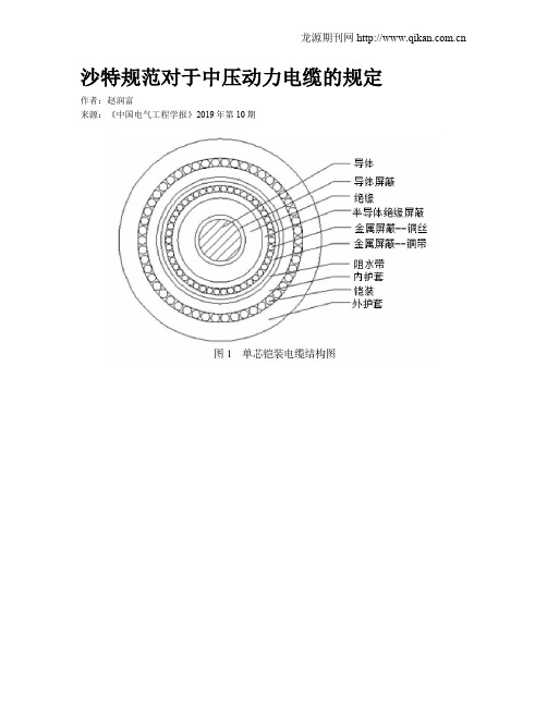
沙特规范对于中压动力电缆的规定作者:赵润富来源:《中国电气工程学报》2019年第10期摘; 要:中压动力电缆结构由内到外分别为导体、导体屏蔽、绝缘、绝缘屏蔽、填充(多芯电缆)、阻水带(根据电缆敷设环境确定是否需要)、内护套、铠装(铠装电缆)、外护套,沙特规范对于电缆的每层结构都有明确规定,此规定主要是基于IEC规范,且结合了AEIC CS8中的部分规定。
关键词:中压动力电缆、IEC规范、AEIC CS81、概述电气工程设计中,电缆是必不可少的材料,很多国外项目十分注重对于电缆质量的检测,因此了解电缆的结构及试验要求是十分有必要的。
沙特规范SES E22-S02(IEC)对中压动力电缆的结构进行了详细的描述,同时规定了中压动力电缆应满足的试验要求。
2、中压动力电缆结构中压动力电缆结构由内到外分别为导体、导体屏蔽、绝缘、绝缘屏蔽、填充(仅针对于多芯电缆)、阻水带(根据电缆敷设环境确定是否需要)、内护套、铠装(仅针对于铠装电缆)、外护套,单芯铠装电缆结构图如图1所示。
2.1 导体导体共分为四种,第1种为实心导体,第2种为绞合导体,第5种为软导体,第6种为比第5种更柔软的导体。
SES中规定导体应为不镀金属退火铜线,第2种,且应满足IEC 60228中的相关规定。
2.2 导体屏蔽导体屏蔽层应该为挤包黑色半导体材料,其允许的操作温度不能低于绝缘允许的操作温度。
挤出层应能很容易地从导体上移除,并不遗留任何残渣,并应满足AEIC-CS8中的相关规定。
2.3 绝缘绝缘应该为挤包固体介质、防水树交联聚乙烯材质,若电缆有更高灵活性的要求时,可按照数据单的要求采用乙丙橡胶绝缘。
绝缘应遵守IEC 60502-2中的相关规定,平均绝缘厚度不能低于标称厚度,任意点的最小厚度不能低于标称厚度x90%-0.1mm。
2.4 绝缘屏蔽绝缘屏蔽应包括半导体绝缘屏蔽和金属屏蔽。
2.4.1 半导体绝缘屏蔽导体屏蔽层应该为挤包黑色半导体材料,挤包层应能很容易地从导体上移除,并不遗留任何残渣,并应满足AEIC-CS8中的相关规定。
沙特阿美工程规程SAEP-341 Equipment Life Cycle Cost Procedure

Previous Issue: 26 July 2009 Next Planned Update: 20 October 2017Page 1 of 14 Primary contact: Odan, Nabeel Mohammad on 966-3-8809506Engineering ProcedureSAEP-34120 October 2012 Equipment Life Cycle Cost Procedure Document Responsibility: Pumps, Seals & Mixers Standards CommitteeSaudi Aramco DeskTop StandardsTable of Contents1 Scope (2)2 Applicable Equipment Typesand Required LCC Data (2)3 Applicable Documents (3)4 Instructions (4)Appendix A – Calculation Methodsfor Life Cycle Cost Analysis (9)Next Planned Update: 20 October 2017 Equipment Life Cycle Cost Procedure1 ScopeThis procedure provides instructions for economically evaluating major equipmentpurchases with regards to their estimated total ownership cost (Life Cycle Cost) toSaudi Aramco over a twenty (20) years period. These costs include procurement andoperation cost (energy cost and quantifiable periodic maintenance) of the equipment.This procedure details the requirements for determining Life Cycle Costs (LCC) forpurchases of major equipment identified in Section 2. The applicable LCC analysisSpreadsheets provide a practical vehicle for performing the required calculations.2 Applicable Equipment Types and Required LCC DataNext Planned Update: 20 October 2017 Equipment Life Cycle Cost Procedure 3 Applicable Documents3.1 Saudi Aramco Materials System Specifications14-SAMSS-531Power Transformers17-SAMSS-502Induction Motors17-SAMSS-510Brushless Synchronous Generator17-SAMSS-520Synchronous Motors31-SAMSS-001Centrifugal Compressors31-SAMSS-004Centrifugal Pumps31-SAMSS-006Integrally Geared Centrifugal Compressor32-SAMSS-021Manufacture of Industrial Boilers32-SAMSS-029Manufacture of Fired Heaters3.2 Saudi Aramco Engineering StandardsSAES-F-001Design Criteria of Fired HeatersSAES-G-005Centrifugal PumpsSAES-K-402Centrifugal CompressorsSAES-P-113Large Electrical MotorsSAES-P-121Power Transformers3.3 Saudi Aramco Standards Data Sheet2741-ENG & Centrifugal Pump Data Sheet for2741-M-ENG Horizontal Pumps and Vertical In-line Pumps2748-ENG & Centrifugal Pump Data Sheet for2748-M-ENG Vertical Line Shaft Pumps8150-ENG & Packaged Integrally Geared Centrifugal8150-M-ENG Air Compressor Data SheetForm 9550-ENG Watertube Boiler Data Sheets (herein referred to asData Sheet)175-323700Manufacture of Fired Heaters3.4 Life Cycle Cost SpreadsheetsThe following spreadsheets are to be used in the analysis and are available in theForms section of the Engineering Standards website:LCC-001Centrifugal Pumps (31-SAMSS-004) *Next Planned Update: 20 October 2017 Equipment Life Cycle Cost ProcedureLCC-002Centrifugal Pump-Motor Trains (31-SAMSS-004)LCC-005Centrifugal Compressors (31-SAMSS-001) *LCC-006Centrifugal Compressor-Motor Trains(31-SAMSS-001)LCC-010Integrally Geared Centrifugal Compressor-MotorTrains (31-SAMSS-006)LCC-019Induction Motors (17-SAMSS-502) *LCC-020Synchronous Motors (17-SAMSS-520) *LCC-023Power Transformers (14-SAMSS-531)LCC-024Boilers (32-SAMSS-029)LCC-024A Dual Fuel Boilers (32-SAMSS-021)LCC-025Fired Heaters (32-SAMSS-029)LCC-025A Dual Fuel Fired Heaters (32-SAMSS-029)* These spreadsheets are to be used when buying stand-alone pumps,compressors, or motors. For equipment trains (i.e., motor driven pump train,etc.), the train work sheets are to be used.4 Instructions4.1 SAPMT Submittal of Project Equipment ListsSaudi Aramco Project Management Team (SAPMT) shall prepare and includethe following items in the project proposal documents:4.1.1 A list of the Project's equipment items that are covered by the aboveSAMSS.4.1.2 A list of equipment items subject to LCC analysis. This list is to beincluded in schedule G of the contract. A copy is to be sent toEstimating Services Division (ESD/PMOD) so that they includeadditional allowances in the ER estimate to cover the differential inequipment cost due to LCC analysis.4.1.3 A list of equipment items with long lead-time delivery that may requireexpedited SAPMT bid development.4.1.4 A list of the latest applicable energy costs obtained from FPD.Next Planned Update: 20 October 2017 Equipment Life Cycle Cost Procedure4.2 Equipment Requiring SAPMT Bid DevelopmentFor equipment requiring SAPMT bid development prior to contract award (longlead equipment), the following steps shall be implemented:4.2.1 Upon receipt of the equipment bids, SAPMT's technical evaluation shallensure that the bids contain the required data needed to perform LCCanalysis.4.2.2 SAPMT shall submit the bids technical data to CSD for review and shallhighlight the technical LCC data (i.e., power, efficiency, operatingfactor) that will be used in the LCC analysis.4.2.3 CSD shall review the technical bid data along with the LCC data elementsand provide comments, if any, to SAPMT within 10 working days.4.2.4 SAPMT shall perform the LCC analysis by utilizing the applicable LCCSpreadsheet (s) to determine the Life Cycle Cost for each acceptablevendor. Other quantifiable cost factors that may significantly impact theeconomic analysis (such as delivery dates) may be included in the LCCanalysis. Inclusions of supplementary cost factors require the priorapproval of the project manager and CSD's concurrence.4.2.5 SAPMT shall calculate the savings (S LCC) in life cycle cost according tothe following equation:S LCC = LCC LIB– LCC LV (1)where:LCC LV is the equipment life cycle cost of the vendor with the lowestoverall LCCLCC LIB is the life cycle cost of the vendor with the lowest initial bid4.2.6 Purchase Order (P/O) shall be placed with the vendor having the lowestLCC (LCC LV) if S LCC is equal to $25000 or 5% of the LIB whichever ishigher.4.2.7 After P/O placement, SAPMT shall submit a copy of the final LCCSpreadsheet(s) to Estimating Services Division (ESD/PMOD) forarchiving and to CSD for information.4.2.8 If Project Management awards to a vendor, a purchase order with apotential performance liability based on the provisions of the applicableSAMSS (penalty clause), and the purchase order is to be transferred(“novated”) to the successful LSTK contractor on the project, ProjectNext Planned Update: 20 October 2017 Equipment Life Cycle Cost Procedure Management and/or Purchasing must include provisions in the NovationAgreement that specifically describe the liability being assumed by thecontractor.4.2.9 The equipment shall be tested at the vendor facility for guaranteedefficiency if required by the applicable Saudi Aramco Materials SystemSpecification (SAMSS) and/or the Project Contract. If the equipmentdoes not meet the specified efficiency, and cannot be corrected withinthe test tolerance as specified in the SAMSS, a penalty shall be imposedon the supplier as defined in the SAMSS and the Purchase order.4.3 Equipment Not Requiring SAPMT Bid DevelopmentFor Contractor procured equipment (all non-long-lead time equipment) thefollowing steps shall be implemented:4.3.1 After evaluating the vendor submittals, the Contractor shall provide thebid technical data, required commercial data per schedule G, and theequipment site delivery date for each vendor to SAPMT for review.4.3.2 SAPMT shall review the information to determine if it contains all of therequired data needed to complete the LCC analysis and shall require theContractor to provide any missing or unacceptable data.4.3.3 SAPMT shall provide a copy of the bid technical data including the LCCdata elements (operating factor, efficiency at normal load point, etc.), toCSD for review.4.3.4 CSD shall review the technical bid data along with the LCC dataelements and provide comments to SAPMT within 10 working days.4.3.5 SAPMT shall perform the LCC analysis by utilizing the applicable LCCSpreadsheet(s) to determine the Life Cycle Cost for each acceptablevendor. Other quantifiable cost factors that may significantly impact theeconomic analysis (such as savings due to early delivery) may beconsidered for inclusion in the LCC analysis. Inclusions ofsupplementary cost factors require the prior approval of the projectmanager and CSD's concurrence.4.3.6 SAPMT shall calculate the savings (S LCC) in life cycle cost according tothe following equation:S LCC = LCC LIB– LCC LV(2)Next Planned Update: 20 October 2017 Equipment Life Cycle Cost Procedure where:LCC LV is the equipment life cycle cost of the vendor with the lowestoverall LCCLCC LIB is the life cycle cost of the vendor with the lowest initial bid4.3.7 SAPMT shall direct the contractor to place the Purchase Order (P/O)with the vendor having the lowest LCC (LCC LV) if S LCC is equal to105% or higher of the compensation to the LSTK Contractor (refer toparagraph 4.3.8).4.3.8 If the COMPANY directs the CONTRACTOR to purchase theequipment from any manufacturer technically qualified by theCONTRACTOR other than the CONTRACTOR's proposed source ofsupply, the COMPANY shall compensate the CONTRACTOR for anydifference between the total delivered equipment cost ofCONTRACTOR's proposed source of supply and that of the COMPANYdirected manufacturer.4.3.9 After P/O placement, SAPMT shall provide a copy of the final LCCSpreadsheet(s) to the Estimating Services Division (ESD/PMOD) forarchiving and to CSD for information.4.3.10 The equipment shall be tested at the vendor facility for guaranteedefficiency if required by the applicable Saudi Aramco Materials SystemSpecification (SAMSS) and/or the Project Contract. If the equipmentdoes not meet the specified efficiency, and cannot be corrected withinthe test tolerance as specified in the SAMSS, a penalty shall be imposedon the contractor as defined in the SAMSS and the Project Contract.4.4 All Direct Charge Purchases Requiring LCC AnalysisFor Direct Charge (D/C) procurement of equipment, the following steps shall beimplemented:4.4.1 The Proponent Requisition Originator shall develop the PurchaseRequisition (PR) or the Request for Quotation (RFQ) for the subjectequipment and forward it to Purchasing for bid development. If therequested equipment requires LCC analysis as specified in the applicableSAMSS, the Requisition shall clearly indicate the required LCC datawhich the bidders need to provide.4.4.2 Upon receipt of the PR or the RFQ, the Purchasing Buyer shall reviewthe indicated line items and specifications to determine if any of theNext Planned Update: 20 October 2017 Equipment Life Cycle Cost Procedure items require LCC analysis.4.4.3 Upon receipt of bids, the Buyer shall request the Proponent RequisitionOriginator to perform the technical evaluation.4.4.4 The Buyer shall obtain the latest applicable energy costs from FPD foruse in the LCC analysis.4.4.5 The Buyer shall perform the LCC analysis by utilizing the applicableLCC Spreadsheet(s) to determine the Life Cycle Cost for all technicallyand commercially acceptable vendors.4.4.6 The buyer shall calculate the savings (S LCC) in life cycle cost according tothe following equation:S LCC = LCC LIB– LCC LV(3)where:LCC LV is the equipment life cycle cost of the vendor with the lowestoverall LCC costLCC LIB is the life cycle cost of the vendor with the lowest initial bid4.4.7 Purchase Order (P/O) placement shall be with the vendor having thelowest LCC (LCC LV) if S LCC is equal to $25000 or 5% of the LIBwhichever is higher.4.4.8 If the equipment cost for the selected equipment is higher than the PR'sauthorized limit, the Requisition Originator (Proponent) shall initiate aChange Requisition to authorize these additional funds.4.4.9 After P/O placement, Buyer shall submit a copy of the final LCCSpreadsheet to Estimating Services Division (ESD/PMOD) for archivingand a copy to CSD for information.The equipment shall be tested at the vendor facility for guaranteedefficiency if required by the applicable Saudi Aramco MaterialsSpecification (SAMSS) and/or the Project Contract. If the equipmentdoes not meet the guaranteed efficiency, and cannot be corrected withinthe test tolerances allowed, a penalty shall be imposed upon the supplierin accordance with the terms and conditions specified in the applicablePurchase Order.Revision Summary13 October 2012 Major revision.Next Planned Update: 20 October 2017 Equipment Life Cycle Cost ProcedureAppendix A – Calculation Methods for Life Cycle Cost AnalysisThis section is included in this SAEP for clarification purpose only. The logic is already included in the Life Cycle Cost Spreadsheets.A.1 Centrifugal Pumps and Centrifugal CompressorsUnless otherwise approved by the Coordinator, Rotating Equipment Division,Consulting Services Department, the Life Cycle Cost (LCC) of the centrifugalpumps and centrifugal compressors is determined from the following formula:LCC = IC + OC (4)where:IC = Initial Cost, $ (Purchase order cost of all equipment being bought)OC = Present value of Operating power Cost, $, for operating period of20 years= P * EF * No. of units being boughtP = Equipment Power in kW, at normal flow rate for actual fluid.EF = Evaluation Factor ($/kW) will be shown on the data sheet and/or inthe quotation request= 11.56 * EC * AHEC = Energy Cost in $/kWhAH = Annual operating Hours= OF * 8760OF = Operating Factor= Number of Operating Units divided by the number of units beingbought.Next Planned Update: 20 October 2017 Equipment Life Cycle Cost ProcedureA.2 Electrical Motor Driven Centrifugal Pump, Electrical Motor Driven CentrifugalCompressor and Electrical Motor Driven Integrally Geared Compressor TrainsUnless otherwise approved by the Coordinator, Rotating Equipment Division,Consulting Services Department, the Life Cycle Cost (LCC) of the electricalmotor driven trains is determined from the following formula:LCC = IC + OC (5)where:IC = Initial Cost, $ (Purchase order cost of all trains being bought)OC = Present value of Operating power Cost, $, for operating period of20 years= P/(Em*EG) * EF * No. of trains being boughtP = Driven equipment Power in kW, at normal flow rate for actualfluid.Em = Motor Efficiency at normal operating load (decimal)EG = Gear Efficiency at normal operating load (decimal). If there is nogear, EG = 1EF = Evaluation Factor ($/kW) will be shown on the data sheet and/or inthe quotation request= 11.56 * EC * AHEC = Energy Cost in $/kWhAH = Annual operating Hours= OF * 8760OF = Operating Factor= Number of operating trains divided by the number of trains beingbought.Next Planned Update: 20 October 2017 Equipment Life Cycle Cost ProcedureA.3 Electrical MotorsUnless otherwise approved by the Coordinator, Electrical Systems MechanicalDivision, Consulting Services Department, the Life Cycle Cost (LCC) of theelectrical motors is determined from the following formula:LCC = IC + OC (6)where:IC = Initial Cost, $ (Purchase order cost of all motors being bought)OC = Present value of Operating power Cost, $, for operating period of20 years= RP * EF * No. of motors being boughtRP = Required Power in kW= P/EmP = Motor load in kW, at normal operating conditions.Em = Motor vendor's Guaranteed Efficiency at normal operating load(decimal)EF = Evaluation Factor ($/kW) will be shown on the data sheet and/or inthe quotation request= 11.56 * EC * AHEC = Energy Cost in $/kWhAH = Annual operating Hours= OF * 8760OF = Operating Factor= Number of operating motors divided by the number of motorsbeing bought.Next Planned Update: 20 October 2017 Equipment Life Cycle Cost ProcedureA.4 Life Cycle Cost Evaluation for Boilers and Fired HeatersUnless otherwise approved by the Coordinator, Mechanical & Civil EngineeringDivision, Consulting Services Department, the Life Cycle Cost (LCC) of theboilers and fired heaters is determined from the following formula:Single Fuel Services:LCC = IC + OC (7)where:IC = Initial Cost, $ (Purchase order cost of all units being bought)OC = Present value of Operating power Cost, $, for operating period of20 years= CF * EF * No. of units being boughtCF = Consumed Fuel (Heat Release) in MMBTU/hr= L/EFFL = Unit load (Duty) at normal condition (MMBTU/hr) provided in thedata sheet by the buyer.EFF = Unit Efficiency (decimal) at normal condition provided by vendor.EF = Evaluation Factor ($-hr / MMBTU) will be shown on the data sheetand/or in the quotation request= 11.56 * EC * AHEC = Energy Cost in $/MMBTUAH = Annual operating Hours= OF * 8760OF = Operating Factor= Number of operating units divided by the number of units beingbought. OF = 1 for process heaters since there is no standbyprocess heaters.Next Planned Update: 20 October 2017 Equipment Life Cycle Cost Procedure Dual Fuel Services:LCC = IC + OCx + OCy (8)where:IC = Initial Cost, $ (Purchase order cost of all units being bought)OCx = Present value of Operating power Cost, $, for operating period of20 years= CFx * EFx * No. of units being boughtOCy = Present value of Operating power Cost, $, for operating period of20 years= CFy * EFy * No. of units being boughtCFx = Consumed Fuel (Heat Release) in MMBTU/hr= Lx/EFFCFy = Consumed Fuel (Heat Release) in MMBTU/hr= Ly/EFFEFx = Evaluation Factor for fuel type x ($-hr / MMBTU) will be shownon the data sheet and/or in the quotation request= 11.56 * ECx * Tx / AHEFy = Evaluation Factor for fuel type y ($-hr / MMBTU) will be shownon the data sheet and/or in the quotation request= 11.56 * ECy * Ty / AHL = Unit load (Duty) at normal condition (MMBTU/hr) provided in thedata sheet by the buyer.EFF = Unit Efficiency (decimal) at normal condition provided by vendor.EC = Energy Cost in $/MMBTUAH = Annual operating Hours= OF * 8760Next Planned Update: 20 October 2017 Equipment Life Cycle Cost Procedure OF = Operating Factor= Number of Operating units divided by the number of units beingbought. OF = 1 for process heaters since there is no standbyprocess heatersNote:x & y are the types if fuel that will be provided in the data sheets by buyer.A.5 Power TransformersUnless otherwise approved by the Coordinator, Electrical Systems Division,Consulting Services Department, the Life Cycle Cost (LCC) of the powertransformers is determined from the following formula:LCC = IC + [No. of transformers being bought * (A*Li+B*Lc)] (9) where:IC = Initial Cost, $ (Purchase order cost of all transformers beingbought)A*Li = Present value of no-load loss cost in $, for operating period of20 yearsB*Lc =Present value of load loss cost in $, for operating period of 20 yearsA = No Load Loss Constant, $/kW= 11.56* E1*T1E1 = Energy Cost, $/kWhT1 = Annual operating Hours, 8760 hrLi = Manufacturer guaranteed no-load loss, kWB = Load Loss Constant, $/kW= 0.49 * ALc = Manufacturer guaranteed load loss, kWCommentary Note:The constant 11.56 is a present value factor based the formulaPV=[(1+i)n-1]/[i(1+i)n], where i is the discount rate (5.9%) expressed as adecimal number and n is the life of the motor (20 years).。
SAEP-352 Welding Procedures Review and Approval
Previous Issue: 31 May 2003 Next Planned Update: 20 October 2014Page 1 of 14Primary contact: Al-Sabti Tareq Ibrahim on 966-3-8760236Engineering ProcedureSAEP-35220 October 2009Welding Procedures Review and Approval Welding Standards Committee MembersAwwami, Adnan Ni'Mah, Chairman Rao, Sanyasi, Vice Chairman Carrera, R LCarswell, Raymond J. Juraifani, Hatim Hamad Keen, Peter DavidMuslim, Husain Muhammad Nasri, Nadhir Ibrahim Niemeyer, Dennis Charles Sabti, Tareq IbrahimSayed Nasir, Ghalib TaherSaudi Aramco DeskTop StandardsTable of Contents1 Scope.............................................................2 2 Conflicts and Deviations................................. 23 Applicable Documents.................................... 24 Definitions and Acronyms............................... 6 5Instructions and Approval Responsibility (7)Table 1 – Welding Procedure Technical Approval Responsibility………..……….. 9 Appendix I – Welding Master Set Preparation and Approval..................... 12 Appendix II – Welding Package Review and Approval Process for Company Projects................................ 13 Appendix III – Welding Package Review and Approval Process forRepair/Maintenance/Alterations (14)Next Planned Update: 20 October 2014 Welding Procedures Review and Approval1 Scope1.1 This procedure specifies the responsibilities for welding procedure review andapproval. This procedure applies to pressure vessels, process equipment orcomponents, piping, pipelines, and structures fabricated to a variety ofstandards, such as but not limited to ASME SEC I, IV, VIII, B31.1, B31.3,B31.4, B31.8 and API STD 560, 620 and 650, and AWS D1.1.1.2 Additional requirements may be contained in Scopes of Work, Drawings, orother Instructions or Specifications pertaining to specific items of work.2 Conflicts and DeviationsConflicts between this Engineering Procedure and any other Saudi Aramco Standardshall be resolved by the Consulting Services Department in writing.3 Applicable DocumentsUnless stated otherwise, all Standards, Specifications, and Codes referenced in thisprocedure shall be of the latest issue (including revisions, addenda, and supplements)and are considered a part of this procedure.3.1 Saudi Aramco ReferencesSaudi Aramco Engineering ProcedureSAEP-310Piping and Pipeline RepairSaudi Aramco Engineering StandardsSAES-D-008Repairs, Alterations, and Rerating of PressuredEquipmentSAES-D-108Storage Tank IntegritySAES-D-116Underground Storage Tank SystemSAES-K-001Heating, Ventilating and Air Conditioning (HVAC)SAES-L-350Construction Requirements for Metallic PlantPipingSAES-L-450Construction Requirements for Cross-CountryPipelinesSAES-L-460Pipelines Crossing Under Roads and RailroadsSAES-L-850Design of Submarine Pipelines and RisersNext Planned Update: 20 October 2014 Welding Procedures Review and Approval SAES-M-001Structural Design Criteria for Non-BuildingStructuresSAES-M-005Design and Construction of Fixed OffshorePlatformsSAES-M-009Design Criteria for Blast Resistant BuildingsSAES-T-744Design Criteria/Installation of CommunicationTowersSAES-W-010Welding Requirements for Pressure VesselsSAES-W-011Welding Requirements for On-Plot PipingSAES-W-012Welding Requirements for PipelinesSAES-W-013Welding Requirements for Offshore StructuresSAES-W-014Weld Overlays and Welding of Clad MaterialsSAES-W-015Strip Lining ApplicationSAES-W-016Welding of Special Corrosion-Resistant MaterialsSAES-W-017Welding Requirements for API TanksSaudi Aramco Materials System Specifications01-SAMSS-010Fabricated Carbon Steel Piping01-SAMSS-017Auxiliary Piping for Mechanical Equipment01-SAMSS-035API Line Pipe01-SAMSS-038Small Direct Charge Purchases of Pipe01-SAMSS-046Stainless Steel Pipe01-SAMSS-333High Frequency Welded Line Pipe02-SAMSS-001Piping Components for Low Temperature Services02-SAMSS-005Butt Welding Pipe Fittings02-SAMSS-006Hot Tap and Stopple Fittings02-SAMSS-008Insulating Joints/Spools for Cathodic Protection02-SAMSS-009Design and Fabrication of Scraper Traps02-SAMSS-010Flanged Insulating Joints/Spools for CathodicProtection02-SAMSS-011Forged Steel Weld Neck Flanges for Low,Intermediate and High Temperature Service 04-SAMSS-035General Requirements for ValvesNext Planned Update: 20 October 2014 Welding Procedures Review and Approval 04-SAMSS-053Steel Lubricated Plug Valves - Flanged andWelding End12-SAMSS-007Fabrication of Structural and Miscellaneous Steel12-SAMSS-014Pre-Engineered Metal Building27-SAMSS-001Packaged Water Cooled Centrifugal Chillers forUtility Services27-SAMSS-002Direct Expansion Air Conditioning Systems forOffshore Facilities27-SAMSS-003Manufacture of Non-Industrial Cooling Towers30-SAMSS-001Diesel Engines31-SAMSS-001Centrifugal Compressor31-SAMSS-002Packaged Reciprocating Plant and Instrument AirCompressors31-SAMSS-003Reciprocating Compressors for Process Air orGas Service31-SAMSS-004Centrifugal Pumps31-SAMSS-005Centrifugal Fluorocarbon Refrigeration Units forIndustrial/Process Services31-SAMSS-006Packaged, Integrally Geared Centrifugal AirCompressors31-SAMSS-009Positive Displacement Pumps - Controlled Volume31-SAMSS-010Submersible Pumps and Motors for Water Welland Offshore Service31-SAMSS-012Shaft Sealing Systems for Centrifugal and RotaryPumps32-SAMSS-001Special Purpose Steam Turbines for Generator Sets32-SAMSS-004Manufacture of Pressure Vessels32-SAMSS-005Manufacture of Atmospheric Tanks32-SAMSS-006Manufacture of Low Pressure Tanks32-SAMSS-007Manufacture of Shell and Tube Heat Exchangers32-SAMSS-008Inlet Air Filtration Systems for Combustion GasTurbines32-SAMSS-009General Purpose Steam Turbines32-SAMSS-010Special Purpose Steam TurbinesNext Planned Update: 20 October 2014 Welding Procedures Review and Approval32-SAMSS-011Manufacture of Air-cooled Heat Exchangers32-SAMSS-013Lubrication, Shaft Sealing and Control Oil Systems32-SAMSS-016Inlet Air Filtration Systems for Centrifugal AirCompressors32-SAMSS-017Side-Entry Mixers32-SAMSS-019Manufacture of Plate and Frame Heat Exchangers32-SAMSS-020Manufacture of Trays and Packing32-SAMSS-021Manufacture of Industrial Boilers32-SAMSS-022Manufacture of Components for Flare Systems32-SAMSS-027Manufacture of Electric Heat Exchangers32-SAMSS-028Manufacture of Double Pipe Heat Exchangers32-SAMSS-029Manufacture of Fire Heaters32-SAMSS-030Manufacture of Small Tanks32-SAMSS-031Manufacture of Clad Vessels and Exchangers32-SAMSS-033Reverse Osmosis Systems32-SAMSS-035Manufacture of Heat Recovery Steam Generator32-SAMSS-036Manufacture of Small Pressure Vessels32-SAMSS-100Combustion Gas Turbines34-SAMSS-611Safety Relief Valves Conventional and BalancedTypes34-SAMSS-612Safety Relief Valves Pilot Operated Types34-SAMSS-711Control Valves45-SAMSS-005Valves and Wellhead Equipment Requirements perAPI SPEC 6A3.2 Industry Codes and StandardsAmerican Petroleum InstituteAPI STD 560Fired Heaters for General Refinery ServicesAPI STD 620Design and Construction of Large, Welded, Low-Pressure Storage TanksAPI STD 650Welded Steel Tanks for Oil StorageAPI STD 1104Welding of Pipelines and Related FacilitiesNext Planned Update: 20 October 2014 Welding Procedures Review and ApprovalAmerican Society of Mechanical EngineersASME B31.1Power PipingASME B31.3Process PipingASME B31.4Pipeline Transportation Systems for LiquidHydrocarbons and other LiquidsASME B31.8Gas Transmission and Distribution PipingSystemsASME SEC I Rules for Construction of Power BoilersASME SEC IV Rules for Construction of Heating BoilersASME SEC VIII Rules for Construction of Pressure VesselsASME SEC IX Welding and Brazing QualificationsAmerican Welding SocietyAWS D1.1Structural Welding Code-Steel4 Definitions and AcronymsApplication Approval: Approval acquired from Inspection Department to applytechnically approved welding procedure. ID generally verifies that the intendedapplication of previously approved welding procedures is within the weldingprocedure's variables (e.g., diameter, thickness, materials, service, etc.) approval range.CSD: Consulting Services Department Welding Specialist/Engineer or CSD'sAppointed Representative (e.g., Aramco Services Company WeldingSpecialist/Engineer).ID: Inspection Department Vendor, Operations or Project Inspector or InspectionRepresentative.PMC: A Program Management Contractor.SAPMT: Saudi Aramco Project Management Team or someone acting on their behalf such as PMC.PMT Designated Welding Representative (PMT DWR): A welding engineer /inspector assigned to and contracted by SAPMT who has the approval authority forproject(s) associated welding procedures.PQR: Performance Qualification RecordNext Planned Update: 20 October 2014 Welding Procedures Review and Approval Technical Approval: Approval of welding procedures acquired from CSD or PMTDesignated Welding Representative. This approval indicates that the weldingprocedure was qualified to Saudi Aramco and/or industry standards or codes and it isacceptable for the intended application. Every page of the welding procedurespecifications should include the reviewer signature and/or approval stamp.Weld and Line Designation Table: A table that lists the applicable weldingprocedures, approval conditions (e.g., low temperature, sour service, etc.), weldingprocess, and any general welding information pertinent to those applicable weldingprocedures.Weld Map: A schematic one line diagram of pressure containing equipment (e.g.,pressure vessel or tank). The map should indicate where each approved weldingprocedure will be applied.Welding Master Set (WMS): It is compilation of welding procedures prepared byvendor/fabricator. It is a standardized set of welding procedures that is used with ageneric Weld and Line Designation Table and/or generic Weld Map, which include the material and service application information.WP: Welding Package.WPS: Welding Procedure Specifications.5 Instructions and Approval Responsibility5.1 CSD shall be the technical approval authority for the followings:a) All Saudi Aramco Project welding procedures for applications listed inTable 1 from either in-kingdom or out of kingdom fabricators andconstruction contractors. Appendix II is a flowchart that indicates thereview process for Saudi Aramco projects.b) "Welding Master Set" submissions for the applications listed in Table 1from in-Kingdom and Gulf Cooperation Council fabricators. SeeAppendix I for details on welding master set's preparation and approval.Appendix II is a flowchart that indicates the review process for SaudiAramco projects. The Welding Master Set (WMS) is submitted to PMTfor CSD's one-time technical approval. When WMS is approved by CSDthen it can be often used in various Saudi Aramco projects if ID approvesthe application.c) Maintenance/repair/alteration applications. Appendix III is a flow chartthat indicates the review process.Next Planned Update: 20 October 2014 Welding Procedures Review and Approval5.2 A PMT designated welding representative assigned to and contracted bySAPMT may be the approval authority for project(s) associated weldingprocedures. He must review the welding procedures for all applications listed inTable 1, and as requested by PMTCSD will interview and approve the PMT designated welding representative.Written examinations may be requested and prepared by CSD, this will dependon the project scope. With coordination with SAPMT, CSD will periodicallyaudit some of his welding procedures review.5.3 For applications not listed or not requiring CSD/PMT DWR review in Table 1the qualified welding procedures shall be available at the fabrication/weldingsite (e.g., vendor shop, field fabrication, etc.) for review by the Inspector, ifrequested. The procedures shall be included in the project or shopdocumentation record books.5.4 If the welding procedure is approved to the latest edition of the weldingstandards, then the fabricator/construction contractor is permitted to use thewelding procedure without CSD/PMT DWR review. The assigned inspectormust verify that the qualification range (e.g., diameter, thickness, material grade,etc.) of the welding procedure is still applicable to the new work.5.5 If the welding procedure is approved to a previous edition of the weldingstandards, then fabricator/construction contractor is permitted to use it, if it wasnot affected by the revisions. The fabricator/construction contractor must writea formal letter to PMT or Engineering/Maintenance Div. indicating that thesubject welding procedure still complies with the latest edition of Saudi AramcoWelding Standards. The assigned inspector must verify that the qualificationrange (e.g., diameter, thickness, material grade, etc.) of the welding procedure isstill applicable to the new work.5.6 If the previously approved welding procedure is invalidated by a change in thewelding standard, a revised welding procedure, along with the old approvedcopy, must be submitted for CSD/PMT DWR review. The assigned inspectormust verify that the qualification range (e.g., diameter, thickness, material grade,etc.) of the welding procedure is still applicable to the new work.Revision Summary20 October 2009 Major revision.Next Planned Update: 20 October 2014 Welding Procedures Review and Approval Table 1 – Welding Procedure Technical Approval ResponsibilityNext Planned Update: 20 October 2014 Welding Procedures Review and Approval Table 1 – Welding Procedure Technical Approval Responsibility (cont'd)Next Planned Update: 20 October 2014 Welding Procedures Review and Approval Table 1 – Welding Procedure Technical Approval Responsibility (cont'd)Notes:1. Formal approval is not required. However, all WPS/PQR/Weld Map documents must be available for the inspectorreview or verification upon his request.2. In special cases the PMT or the Engineering/Maintenance Division may request CSD procedure review for anyapplication. This may be done even though procedure review is not required according to Table 1 or is not listed inTable 1.Next Planned Update: 20 October 2014 Welding Procedures Review and ApprovalAppendix I – Welding Master Set Preparation and Approval1. Each fabricator/vendor awarded a contract or purchase order will compile all CSDrevised previously approved welding procedures and any welding procedures,intended to be used in Saudi Aramco projects.2. Revised previously approved welding procedures must be submitted in new forms,unsigned, and the approved copy is attached to compare welding parametersbetween the two copies.3. The master set must include typical "Weld Maps", "Weld Description" sheet,"Request for Welding Procedure Approval" form and any supporting documentrequired to be submitted by Saudi Aramco Welding Standard (SAES-W-010,SAES-W-011, etc.). It is recommended that a distinct identification system isused for the WPS and the revision number (e.g., WPS # is WMS P1-P8-1 and therevision # is M0, here both WMS and M indicate that the welding procedure ispart of welding master set).4. The PQRs must be either the originals, certified/stamped copies, or colored copiesof the originals. The qualification tests must be performed by independent testingagency approved by Saudi Aramco (Contact CSD Welding Group to get theupdated list of the approved independent test agencies).5. The time required to review each master set will depend on the number of thesubmitted welding procedures and the pertinent technical welding requirements(e.g., PWHT, hardness test, impact toughness test, etc.). The table below lists theestimated time to review welding master sets.Estimated Time to Review Welding Master Sets6. After the initial technical approval, the welding procedures can be applied invarious company projects if ID approves the application.7. The fabricator/ Construction Contractor must continuously review the approvedwelding procedures to ensure their conformance with the latest applicable SaudiAramco Welding Standards and Industry Codes.Next Planned Update: 20 October 2014 Welding Procedures Review and Approval Appendix II – Welding Package Review andApproval Process for Company ProjectsNext Planned Update: 20 October 2014 Welding Procedures Review and Approval Appendix III – Welding Package Review andApproval Process for Repair/Maintenance/Alterations。
阿美规范注意的方面(1)
从质量管理来讲,沙特项目与国内项目的主要差异在于:业主和承包商在施工过程中,对规范的理解、要求以及执行力上存有很大差异。
现将阿美规范中,需要施工方和承包商注意的事项罗列出来,这些事项都是在哈维亚项目在施工过程中,遇到的棘手问题,TR和SINOPEC解决起来,耗时耗力,对工期和费用影响比较大。
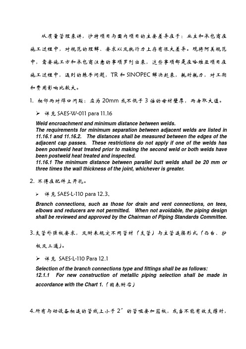
1.相邻两对焊口间距:应为20mm或不低于3倍的母材壁厚,两者取大值。
详见SAES-W-011 para 11.16Weld encroachment and minimum distance between welds.The requirements for minimum separation between adjacent welds are listed in11.16.1 and 11.16.2. The distances shall be measured between the edges of theadjacent cap passes. These restrictions do not apply if one of the welds has been postweld heat treated prior to making the second weld or both welds have been postweld heat treated and inspected.11.16.1 The minimum distance between parallel butt welds shall be 20 mm orthree times the wall thickness of the joint, whichever is greater.2.不得在配件上开孔。
详见SAES-L-110 para 12.3,Branch connections, such as those for drain and vent connections, on tees, elbows and reducers are not permitted. When not avoidable, the piping design shall be reviewed and approved by the Chairman of Piping Standards Committee.3.支管补强板要求,及附表规定不同管材(支管)与主管连接形式(凸台、护板及三通)。
沙特阿美工程规程SAEP-1027 Pressure Relief Valve Conventional and Balanced Types
Previous Issue: 19 August 2008 Next Planned Update: 17 July 2017Revised paragraphs are indicated in the right marginPrimary contact: Awami, Luay Hussain on 966-3-880-1341Engineering ProcedureSAEP-102717 July 2012Pressure Relief Valve Conventional and Balanced Types Document Responsibility: Instrumentation Standards CommitteeSaudi Aramco DeskTop StandardsTable of Contents1 Scope (2)2 Applicable Documents (2)3 Detailed Instructions for Saudi AramcoForm 8020-611-ENG (3)4 Responsibilities (14)5 Definition of Terms (14)Next Planned Update: 17 July 2017 Pressure Relief Valve Conventional and Balanced Types1 ScopeSaudi Aramco Engineering Procedures (SAEPs) establish instructions andresponsibilities associated with various engineering activities. This document contains the instructions for entering data into Form 8020-611-ENG, InstrumentationSpecification Sheet, Pressure Relief Valve Conventional and Balanced Types.2 Applicable DocumentsThe requirements contained in the following documents apply to the extent specified in this procedure.2.1 Saudi Aramco DocumentsSaudi Aramco Engineering StandardsSAES-J-600Pressure Relief DevicesSAES-L-140Thermal Expansion Relief in PipingSaudi Aramco Engineering Form8020-611-ENG Instrument Specification Sheet, Pressure ReliefValves- Conventional & Balanced Types2.2 Industry Standards and CodesAmerican Petroleum InstituteAPI RP 520 Sizing, Selection and Installation of Pressure -Relieving Devices in RefineriesAPI RP 526 Flanged Steel Pressure Relief ValvesAmerican Society of Mechanical EngineersASME B31.3 Process PipingASME B31.4 Pipeline Transportation Systems for LiquidHydrocarbons and Other LiquidsASME B31.8 Gas Transmission and Distribution Piping SystemsASME SEC I Rules for Construction of Power BoilersASME SEC VIII Rules for Construction of Pressure ValvesAmerican Society for Testing and MaterialsASTM A216 Standard Specification for Steel Castings, Carbon,Next Planned Update: 17 July 2017 Pressure Relief Valve Conventional and Balanced TypesSuitable for Fusion Welding, for High-Temperature ServiceCrane Co.Technical Paper No. 410 Flow of Fluids through Valves, Fittings, and Pipe 3 Detailed Instructions for Saudi Aramco Form 8020-611-ENGLine 1 Instrument Tag Number for the PZV. This number is found on theP&ID. For new PZV's a new Instrument Tag Number must be assigned.Line 2 Service - Location: Enter the Equipment Number, Line or ProcessSystem the PZV is protecting. On line below specify the service asLiquid, Gas or Vapor.Line 3 Serial Number– The Serial Number of the PZV to be used as a futurereference by the manufacturer to trace all of the original specificationson the PZV.Line 4 P&ID NumberLine 5 Manufacturer - Enter the PZV Manufacturer Name if known.Line 6 Model Number - Enter the PZV Manufacturer's Complete ModelNumber (Vendor to Verify).Line 7 Material Source - Requisition Number (If known, Enter)Line 8 Material Source - SAMS Stock No. (If known, Enter)Line 9 Design Type - (e.g., - Conventional, Balanced Bellows, BalancedBellows w/ Aux. Piston)Line 10 Body Material - Refer to API RP 526 “Flange Safety Relief Valves”and SAES-J-600 materials. Generic Carbon Steel, Stainless Steel, etc., issufficient until the valve is bought, then more detail should be substitutedsuch as (ASTM A216 grade WCB).Line 11 Body Size - Refer to API RP 526 “Flange Safety Relief Valves” forstandard body sizes. (e.g., 4” inlet, 6” outlet, ¾” FNPT inlet, 1” MNPToutlet). F = female and M = male. NPT is National Pipe Thread.Line 12 Body Connection Rating - (e.g., - 300# ANSI Flanged, 3000#Threaded) Refer to API RP526 “Flange Safety Relief Valves” forstandard PZV connection sizes. Per SAES-J-600 minimum inlet flangerating is 300# ANSI.Next Planned Update: 17 July 2017 Pressure Relief Valve Conventional and Balanced Types Line 13 Flange Face Type - (e.g., - RF for Raised Face, RTJ, for Ring Joint, FF - for Flat Faced, N/A if threaded)Line 14 Seat Type - (e.g. - Metal, Soft (O-ring), or manufacturer specific, i.e.,Thermoflex®, Flex-disc®, etc.)Line 15 Bonnet Generally steam service valves are specified with an OPENbonnet to reduce the temperature effects on the spring. All others arenormally CLOSED.With Open Bonnets, the spring is completely visible.A Bellows Valves is normally specified as a Closed Bonnet even thoughit is vented.Line 18 Nozzle and Disc Material - Enter Nozzle and Disc Material.Line 19 Guide Material - Enter the Stem Guide MaterialLine 20 Spring Material - Enter the material of the spring (e.g., - carbon steel,316 S.S., Monel, Hastelloy C, Iconel, Tungsten).Line 21 Spring Coating - (If any - e.g., Nickel Plated, Painted, AluminumMetalized)Line 22 Bellows - Enter the bellows material (e.g., - 316 SS, Monel, 316L SS,Hastelloy Inconel).Line 24 Cap - (This is the cap that covers the setpoint adjustment). Indicatewhether it is Screwed or Bolted. Standard configuration is screwed.Line 25 Lifting Lever - The purpose of the lifting lever is to enable the user toopen the valve when the pressure under the valve disc is lower than theset pressure. The lifting lever is required for Air, Steam and Hot Water.ASME SEC VIII UG-136 (a) (3). The Plain or Open lever assembly isnot pressure-tight and may leak to the atmosphere. Typically used on airand steam applications. Packed levers ensure leakage does not occureither when the valve is open or when backpressure is present.Line 26 Test Gag - The test gag is used to prevent the safety valve from lifting.This is normally only specified for in-place testing of multiple steamvalve installations or where hydrotesting the system is required.Line 27 Vent with Bug Screen - Vents the Bonnet of the PZV. Yes, for Bellows Valves. No, for Conventional Valves.Next Planned Update: 17 July 2017 Pressure Relief Valve Conventional and Balanced Types Line 28 Auxiliary Piston - Auxiliary Balance Piston - Required for Bellowsvalves where a bellows failure may cause an unacceptable increase insetpressure or decrease in flowing capacity from built-up backpressure.Line 29 Liquid Trim - Yes, if the valve is in liquid service. Yes, if the valve isin two-phase flow and greater than 50% of the total MASS flowrate isliquid.Line 31 ASME Code - Choose whether the PZV will be installed as ASME SEC VIII (Pressure Vessels - Stamped UV) or ASME SEC I (Steam Boiler -Stamped V). ASME SEC VIII stamped valves are required for PZVsinstalled on ASME B31.3 “In-plant piping”, ASME B31.4 “LiquidTransport Pipelines”, or ASME B31.8 “ Gas Transmission Pipelines”.Enter “n/a” for relief valves used in service below 15 PSIG such as onAPI 2000 tanks.Line 32 Fire or Blocked Discharge - Choose whether the worst case relievingscenario is either Block Discharge or Fire. If other, then enter n/a and goto Line 33.Line 33 Other - (Basis of Selection), Other than Line 32 worst case relief (e.g., - Thermal Relief, Exchanger Tube Failure, Loss of Reflux, Loss ofCooling Fans, etc.)Line 35 Process Fluid - (e.g., Hydrocarbon, Water, Gasoline, Oil, etc.)Line 36 Corrosive Compounds - Name any significant corrosive compoundssuch as H2S, Sour water, etc.Line 37 Required Capacity - This capacity is given at standard conditions. It is the maximum (worst case) relieving scenario for the basis of selection.Line 38 MW or SG @ Relieving Temperature - The molecular weight of thegas or vapor or the Specific Gravity (referenced to water). The specificgravity is stated at the flowing (relieving) conditions.Line 39 Viscosity @ Relieving Temperature in Centipoise.Line 40 Weight % Flashing / Molecular Weight of the VaporApplicable to liquids only. Flashing liquids require specialconsideration. The correct relief valve size lies between that obtainedfrom the liquid formula and that obtained from the vapor formula,usually closer to the liquid. Flashing probably occurs at the throat,where velocity is sonic. The most reasonable approach is to determineNext Planned Update: 17 July 2017 Pressure Relief Valve Conventional and Balanced Types the liquid portion and the vapor portion separately, compute the arearequired for each quantity, and add them together.Assume an isenthalpic (adiabatic) process.% Flashing = H1-H2 /H LVwhere:H1 = Enthalpy in BTU/lb of saturated liquid at upstream temperature.H2 = Enthalpy in BTU/lb of saturated liquid at downstream pressure.H LV = Latent Heat of Vaporization BTU/lb at downstream pressure.An alternative to the above is to use a process simulation package toperform the flash calculation. Saudi Aramco approved simulationpackages are HYSYS and Pro2 by Simulation Sciences.Balanced Bellows valves may be necessary as a safety precaution whenthe increased downstream PZV body pressure, due to flashing flowconditions, is excessive or cannot be predicted with certainty.Line 41 Temperature at Normal Conditions and at Relief.For Blocked discharge of liquids, the relief temperature is typically thenormal temperature. For blocked discharge of gas on the outlet of acompressor, consider the increased temperature due to the increasedrelieving pressure. For the fire case, the relief temperature of the vaporis the boiling point of the liquid at the relieving pressure.Line 42 Pressure at Normal Conditions and Design Pressure.Design Pressure refers to (at least) the most severe conditions ofcoincident temperature and pressure expected during operation.Design pressure is always equal to or less than the MAWP. Used todetermine the minimum permissible thickness or physical characteristicsof different parts of the vessel. Typically, a corrosion allowance is thenadded to the calculated thickness. If the MAWP is greater than thedesign pressure then this usually means the thickness calculated for thedesign pressure was not commercially available and the next largerrolled plate or pipe was used.Line 43 Set PressureThe set pressure for a single relief valve installation on a vessel orprotected vessel system may not exceed 100% of the MAWP.Next Planned Update: 17 July 2017 Pressure Relief Valve Conventional and Balanced Types Set pressure staggering is allowed for Multiple PZV installations as follows:- First Valve - The maximum allowable set pressure shall not exceed100% of the MAWP- Additional Valve(s) - Set pressures may be staggered but shall notexceed 105% of the MAWP.- Supplemental Valves - (For additional hazard created by exposure tofire or heat). The set pressure shall not exceed 110% of the MAWP.Set pressure shall not exceed 110% for thermal relief valves on piping.(SAES-L-140).Line 44 Constant Superimposed Back-Pressure (See Definition).Line 45 Variable Superimposed Back-Pressure (See Definition).Line 46 Built-up Back-Pressure (See Definition).Line 47 Total Maximum Backpressure = Superimposed plus Built-upbackpressure.Line 48 Cold Differential Test Pressure (CDTP)The cold differential set or test pressure is the actual pressure at which thevalve will open on a test stand. As PZVs are usually set and tested atambient temperature with no backpressure, the CDTP includes anynecessary correction for the actual application, based upon backpressureand / or temperature. Backpressure correction is only needed forConventional PZVs and it addresses constant backpressure only.CDTP (Conventional PZV) = (Set Pressure – Constant SuperimposedBack Pressure) * Temperature Correction Factor.CDTP (Bellows or Pilot PZV) = Set Pressure * Temperature CorrectionFactor.The Pressure adjustment for temperature is specific to the Manufacturerand PZV Model. Consult the manufacturer for discharge temperaturesabove 150°F.Line 49 Net Spring Setting (for Spring Selection)The setting that is adjusted for constant backpressure for conventionalPZVs. This is used for spring range selection.Next Planned Update: 17 July 2017 Pressure Relief Valve Conventional and Balanced TypesLine 50 Accumulation in Percent = (Relieving Pressure - MAWP) / MAWP] *100 Overpressure in PSI = Relieving Pressure – Set PressureExample:Set Pressure = 95 PSIGMAWP = 100 PSIGRelieving Pressure in Vessel = 110 PSIGAccumulation = [(110 -100) / 100] *100 = 10%Overpressure = 110 PSIG - 95 PSIG = 15 PSIGLine 51 Blowdown in Percent = (Set Pressure - P closed) / Set Pressure ) * 100Where P closed = Pressure at which the relief valve closes after openingExample:Setpressure = 100 PSIGRelief Valve Closes at 96 PSIG after opening.Blowdown = [(100 PSIG - 96 PSIG) / 100 PSIG] * 100 = 4%Blowdown should be specified as 2-4% for PZV's in ASME SECI steam service. For other valves 7-9% is generally acceptable.Line 52 Discharges To:Examples:Atmosphere, Grade, Open Funnel, Closed Sewer, Relief Header, FlareHeader, Storage Tank, Pump Suction, etc.Line 53 Maximum Allowable Bellows Back PressureTo prevent damage to, or rupture of, the bellows. This information is tobe supplied by the selected Vendor.Check that the sum of the Superimposed and Built-up Backpressure isnot greater than Line 51.Page 2 – ISS 8020-611-ENGLine 55 Instrument Tag Number - Required on every ISS individual sheet.Line 56 Calculated Maximum Tail Pipe VelocityThis is derived by dividing the Maximum Required Flowrate by thecross-sectional area of the discharge flange. (Ft/Sec) “N/A” if Line 56 isNext Planned Update: 17 July 2017 Pressure Relief Valve Conventional and Balanced Types “N/A”.Line 57 Design Limit on Tail Pipe VelocityRelief System Evaluation for stress on the discharge flare header.For Line 56 choose either Yes or N/A to indicate whether detailed flareheader sound pressure level calculations are required.Input “No” for Line 57 if any of the following items 1-3 are True.1. The PZV does not discharge to a closed system.2. The PZV is for liquid relief.3. The Screening Process indicates obvious safe sound pressure levels.Screening ProcessPerform either Test I, II or III depending on the PZV downstream pipingconfiguration.If the test result is False, then N/A may be entered into Line 57. If thetest results is True, then a Yes is entered into Line 57 to indicate thatfurther downstream piping sound pressure levels are necessary.The calculation sound pressure levels are outside of the scope of the8020-611-ENG specification sheet. The Process Engineering Divisionmay be consulted for help with the detailed sound pressure levelcalculations.Test I - PZV Downstream line size 16 in. and greater:Screening Test: The Mass Flow Rate is greater than91,000 kg/hr (200,000 lb/hr) OR the pressure ratio is greaterthan 3? (True / False)Test II - PZV Downstream line sizes 8 in. to 14 in.Screening Test: The downstream line velocity is greater than50% sonic (0.5 Mach) AND the pressure ratio is greater than 3.(True / False)Test III - PZV Downstream line size less than 8 in. AND is swaged upOR“Teed” to an 8 in. or larger line size.Screening Test: The downstream line velocity is greater than50% sonic (0.5 Mach) AND the pressure ratio is greater than 3.(True / False)Next Planned Update: 17 July 2017 Pressure Relief Valve Conventional and Balanced TypesScreening Process Definitions:Line Velocity = (Maximum PZV Discharge Flowrate)(Cross-sectional area of downstream PZV piping)Sonic Velocity = SQRT (kqRT)(See Crane - “Flow of Fluids” Chapter 1 Equation 1 - 10.)Pressure Ratio = (Built-up Pressure + Normal Flare Header Pressure + 14.7)(Normal Flare Header Pressure + 14.7)Built-up Pressure = See Definitions of TermsLine 58 Calculated Line Piping Pressure LossCalculate the Inlet Pressure drop at the maximum rated relief capacity ofthe PZV. (The stamped rated capacity of the valve).The inlet pressure losses are the accumulative pressure drops due tofriction (as a function of pipe size and length and fluid velocity),entrance and exit losses where they exist, and losses due to valves andfittings. (See Crane “Flow of Fluids” Chapter 1 for more details.)Line 59 Inlet Pressure Loss Limit (3% Set Pressure)Verify that inlet piping pressure loss does not exceed 3% of the setpressure limit (the inlet piping should be as short as possible to minimizethe pressure drop).Inlet Pressure Loss Limit = (Set Pressure * .03)An engineering analysis of the valve performance at higher inlet lossesmay permit increasing the allowable pressure loss above 3%, however,this would require a waiver.Line 63 Spring Range in PSIG (e.g., 80-150 PSIG)This is supplied by the vendor. For existing springs, the range may befound by supplying the stamped part number to Supervisor, OperationsInspection Engineering Unit, Dhahran. Spring selection is based on theCDTP without considering any temperature correction factor.Some manufacturers consider spring Codes and Ranges confidential.Line 64 Manufacturers Spring Number (Manufacturers Part Number)Line 66 Calculated Orifice Area (Square Inches) - Obtained from the APINext Planned Update: 17 July 2017 Pressure Relief Valve Conventional and Balanced Types formulas used on 8020-611-ENG Sheet 3 Lines 98-101.Line 67 Selected API Orifice and Area - The standard effective orifice areasand the corresponding letter designations are listed below as defined byAPI RP 526 Section 3.1 Table 1.Line 68 Actual Orifice Area - This information is the actual orifice area and issupplied by the vendor or may be found in the vendor product literature.Lines 70-73 Multiple Relief ValvesCheck whether multiple valves better serve the application.(SAES-J-600 Paragraph 8.14).Check whether a spare valve is needed for maintenance(SAES-J-600 Paragraph 8.15).Line 70 Set Pressure of Low Valve - (No higher than the MAWP)Exception:Thermal reliefs may be set up to 110% of MAWP per SAES-L-140.Line 71 Set Pressure of Intermediate Valve - (No higher than the 1.05 * MAWP)Next Planned Update: 17 July 2017 Pressure Relief Valve Conventional and Balanced Types Line 72Set Pressure of High Valve - (No higher than the 1.05 * MAWP) Line 73 Set Pressure of Spare Valve - (The Spare Valve is normally set at theset pressure of the low valve.)Page 3 – ISS 8020-611-ENGSheet 3 Note: The Required Orifice Area is to be calculated. Select anappropriate equation. Equation 98 is used for all Gas and VaporCalculations except for a Fire Case on a Dry Gas Filled Vessel, in whichcase Equation 101 is used. Equation 99 is used for all steam PZVs andEquation 100 is used for Certified Liquid Service. Certified means thatthe valve is Code stamped and has liquid trim. See API RP 520 Part Ifor any further clarifications.Line 77Instrument Tag Number - Required on every ISS individual sheet. Line 78 Required Orifice Area (A) in Square Inches - This is the area requiredto flow the worst case relieving scenario. The value A is determined bythe appropriate equation chosen from line 98-101.Commentary Note:For lines 77-95, enter data only for the variables that are specific for thesizing equation selected. All other variable may be left blank.Line 79 Exposed Surface Area of Vessel (A') in Square Feet - For GasExpansion in dry vessels during a fire case only (Line 101). Calculatethe entire surface area of the vessel. (No credit given for insulation).Line 80Specific Heat Coefficient (C) - This factor is used required to calculatethe Valve Factor in Line 79. Table 9 in API RP 520 Part I shows thisvalue as a function of the ratio of specific heats Cp/Cv = k . The value ofC may be calculated directly from the Specific Heat Ratio (k). C k k + k+k -=⎛⎝ ⎫⎭⎪5202111 Example: For Air k = 1.40, C = 356Line 81 Valve Factor (F') ()F CK T T T D '...=-014061112506506ωNext Planned Update: 17 July 2017 Pressure Relief Valve Conventional and Balanced Types Where: Tω= vessel wall temperature, in (°R) andT1= gas temperature, absolute, in (°R), at the upstreampressure, determined from the following relationship:TPPT 11 =ηηWhere: Pη= Normal operating gas pressure, in PSIA andTη= Normal operating gas temperature, in (°R). Line 82 Specific Gravity (G) - The specific gravity of the liquid at the flowing temperature referred to water = 1.00 at 70 °F. Used for liquid sizing. Line 83 Coefficient of Discharge (K D)- This is the effective coefficient of discharge when using the API sizing equations. If the Manufacturer'sactual Coefficient of Discharge is unknown, then use .975 for gas/vaporsizing calculations or .650 for liquid sizing.Line 84 Back Pressure Correction Factor (K b ) - This is the capacitycorrection factor due to back pressure. The back pressure correctionfactor applies to balanced-bellows valves only. K b values can bedetermined from Figure 27 of API RP 520 Part I. (K b = 1 for backpressure less than 30% of the set pressure.)Line 86 Superheated Steam Correction Factor (K SH) - For saturated steam at any pressure, K SH = 1. For Superheated steam, K SH values can bedetermined from Table 10 of API RP 520 Part I.Line 87 Napier Correction Factor (K N) = 1 where P1 < 1515 PSIA.K N = (0.1906P1– 1000) / (0.2292P1– 1061), where P1 > 1515 PSIAand < 3215 PSIA.Line 88 Back Pressure Correction Factor (K W) - This is for balanced-bellows valves in liquid service with back pressure. For atmospheric backpressure, K W = 1. Conventional valves require no special correction.K W values can be determined from Figure 31 of API RP 520 Part I. Line 89 Viscosity Correction Factor (K V) - This is the correction factor due to viscosity. K V values can be determined from Figure 32 of API RP 520Part I.Line 90 Molecular Weight (M) - This is the molecular weight of the gas or vapor. This value should be obtained from the process data.Next Planned Update: 17 July 2017 Pressure Relief Valve Conventional and Balanced Types Line 91 Relieving Pressure (P1) - This is the upstream relieving pressure, inPSIA. It consists of the set pressure (P) plus the allowable overpressureplus atmospheric pressure.Line 92 Set Pressure (P) - See the definition of set pressure.Line 93 Back Pressure (P b) - See the definition of back pressure.Line 94 Relieving Temperature (T) - This is the relieving temperature of theinlet gas or vapor in °R. (Degrees Rankine = Degrees Fahrenheit +459.67).Line 95 Liquid Flow (Q) - This is the flow rate at the flowing temperature, inU.S. gallons per minute (GPM).Line 96 Gas/Vapor/Steam Flow (W) - This is the required flow through thevalve, in pounds per hour (LB/HR).Line 97 Compressibility Factor (Z) - This is the compressibility factor for thedeviation of the actual gas from a perfect gas, a ratio evaluated at inletconditions.Lines 98-101 Area EquationsSelect the appropriate equation. Write the equation vertically in thespace provided showing the value for each variable and the resultantcalculated area. For Electronically filled in sheets, it is permissible toshow the end calculation result.4 Responsibilities4.1 Instrumentation UnitThe Instrumentation Unit is responsible for keeping this document and theISS Form 8020-611-ENG current and accurate.4.2 Originating EngineerIt is the responsibility of the Originating Engineer to complete ISS Form8020-611-ENG for conventional and bellows operated relief valves before thePZV is entered into the Relief Valve Program for testing and inspection.5 Definition of TermsAccumulation: the pressure increase in the vessel over the maximum allowableworking pressure with the valve, or valves, open and at required relieving capacity; it isNext Planned Update: 17 July 2017 Pressure Relief Valve Conventional and Balanced Types expressed as a percentage of Maximum Allowable Working Pressure, or in kPa(ga) or(psig). The permissible accumulation for various conditions is specified in the ASMECodes.Commentary Note:Accumulation is the same as overpressure when the PZV is set at the MaximumAllowable Working Pressure of the vessel.Back Pressure: the pressure on the discharge side of a relief valve. Different types of back pressures are:a) Superimposed Back Pressure: the pressure on the discharge side of a reliefvalve, against which the valve must begin to open. It may be constant or variable.b) Built-up Back Pressure: the pressure on the discharge side of a relief valvedeveloped as a result of flow due to the valve in question relieving into thedischarge header system. Where multiple valves relieve under a singlecontingency, the back pressure increase in the discharge system as a result of allinvolved valves relieving, determines the built up back pressure.Built-up Back Pressure is calculated by adding all of the discharge header pressuredrops. The pressure losses are the accumulative pressure drops due to friction (asa function of pipe size and length and fluid velocity), entrance and exit losseswhere they exist, and losses due to valves and fittings. (See Crane “TechnicalPaper No. 410” Chapter 1 for more details.)Built-up back pressure may be taken as zero for PZV's that discharge toatmosphere through a full size elbow and short discharge pipe leg.Balanced Safety Relief Valve: a pressure relief valve which incorporates means ofminimizing the effect of back pressure on the operational characteristics (openingpressure, closing pressure, and relieving capacity).Blowdown: the difference between the set pressure and the resetting pressure of arelief valve, expressed as a percentage of the set pressure or in kPa (psig).“Cold” Differential Test Pressure: the pressure in kPa (psig) at which a relief valve is adjusted to open on the test stand. This pressure includes the correction for maximumsuperimposed back pressure (for conventional non-bellows valve only) and/ortemperature service conditions.Conventional Safety Relief Valve: a pressure relief valve which has its spring housing vented to the discharge side of the valve. The operational characteristics (openingpressure, closing pressure, and relieving capacity) are directly affected by changes ofthe back pressure on the valves.Next Planned Update: 17 July 2017 Pressure Relief Valve Conventional and Balanced Types Design Pressure: the pressure, exclusive of any static heads, used to determine theminimum permissible thickness or physical characteristics of the different parts of thevessel.Disc: the pressure containing movable element of a pressure relief valve which effects closure.Lift: the amount the disc rises above the seat in pressure relief valves.Maximum Allowable Working Pressure (MAWP): the maximum pressure in kPa(psig) permissible at the top of a completed vessel in its operating position for adesignated temperature. It is the highest pressure at which a relief valve may be set tobegin to open.Nozzle: a pressure containing element which constitutes the inlet flow passage andincludes the fixed portion of the seat closure.Operating Pressure: the pressure at the top of a pressure vessel at which the vesselsnormally operates.Overpressure: the pressure increase over the set pressure of the primary relief valve.It is the same as accumulation when the relief valve is set at the maximum allowableworking pressure of the vessel.Rated Capacity: the percentage of measured flow at an authorized percentoverpressure permitted by the applicable code. Rated capacity is generally expressed in pounds per hour (lbs/hr) for vapors; standard cubic feet per minute (SCFM) for gases;and in gallons per minute (GPM) for liquids.Relief Valve: an automatic pressure-relieving device actuated by the static pressureupstream of the valve, and which opens in proportion to the increase in pressure above set pressure. It is used primarily for liquid service.Commentary Note:For the sake of simplicity all pressure relief devices (valves) referred to in this procedureare called “PZV”.Relieving Pressure: the pressure in the protected vessel with the relieving devices full open. It is the set pressure plus the actual overpressure. Relief valves shall be sized to prevent the relieving pressure from exceeding the Maximum Allowable WorkingPressure plus the allowable accumulation.Safety Relief Valve: an automatic pressure-relieving device suitable for use as either a safety or relief valve. It is used in gas or vapor service or for liquid.。
- 1、下载文档前请自行甄别文档内容的完整性,平台不提供额外的编辑、内容补充、找答案等附加服务。
- 2、"仅部分预览"的文档,不可在线预览部分如存在完整性等问题,可反馈申请退款(可完整预览的文档不适用该条件!)。
- 3、如文档侵犯您的权益,请联系客服反馈,我们会尽快为您处理(人工客服工作时间:9:00-18:30)。
Previous Issue: 28 April 2009 Next Planned Update: 22 May 2016Revised paragraphs are indicated in the right marginPage 1 of 15Primary contact: Maatoug, Maatoug A on 966-3- 8747960Engineering ProcedureSAEP-2222 May 2011Tank Calibration RequirementsDocument Responsibility: Custody Measurement Standards CommitteeSaudi Aramco DeskTop StandardsTable of Contents1 Scope............................................................2 2 Conflicts and Deviations................................ 23 Applicable Documents................................... 24 Definitions and Acronyms.............................. 35 Instructions.................................................... 56 Responsibilities.............................................. 87 Activity Matrix.............................................. 10 Attachment I – Required Information on the Tank Capacity Table................. 12 Attachment II – Qualifications of theThird Party Inspection Agency (15)Next Planned Update: 22 May 2016 Tank Calibration Requirements 1 ScopeThis procedure establishes the instructions and responsibilities for the calibration ofall Saudi Aramco royalty/custody tank gauging applications. This procedure is alsoapplicable to the inventory tanks that have the potential to be used for custody orroyalty measurement applications in case of the metering system failures. Organizations for which responsibilities are specified include, but are not limited to:∙The Proponent Organization∙Saudi Aramco Project Management Team (SAPMT)∙Process & Control Systems Department (P&CSD)2 Conflicts and Deviations2.1 Any conflicts between this procedure and other applicable Saudi AramcoEngineering Standards (SAESs), Materials System Specifications (SAMSSs),Standard Drawings (SASDs), or industry standards, codes, and forms shall beresolved in writing by the Manager, Process & Control Systems Department ofSaudi Aramco, Dhahran.2.2 Direct all requests to deviate from this procedure in writing in accordance withSAEP-302 to the Manager, Process & Control Systems Department of SaudiAramco, Dhahran.2.3 Direct all requests for interpretation of this procedure in writing to the Chairman,Custody Measurement Standards Committee for resolution. The Chairman,Custody Measurement Standards Committee shall be solely responsible fordetermining whether a proposed request meets the requirements of this procedure.3 Applicable DocumentsThe procedures covered by this document shall comply with the latest edition of thereferences listed below, unless otherwise noted:3.1 Saudi Aramco ReferenceSaudi Aramco Engineering ProcedureSAEP-302Instructions for Obtaining a Waiver of aMandatory Saudi Aramco EngineeringRequirementNext Planned Update: 22 May 2016 Tank Calibration Requirements3.2 Industry Codes and StandardsAmerican Petroleum Institute (API) Manual of Petroleum MeasurementStandards (MPMS)Chapter 2.2A Measurement and Calibration of UprightCylindrical Tanks by the Manual StrappingMethodChapter 2.2B Calibration of Upright Cylindrical Tanks usingthe Optical-Reference Line MethodChapter 2.2C Calibration of Upright Cylindrical Tanks usingthe Optical-Triangulation MethodChapter 2.2D Calibration of Upright Cylindrical Tanks usingthe Internal Electro-optical Distance RangingMethodChapter 2.2E Calibration of Horizontal Cylindrical Tanks-Part 1: Manual MethodsChapter 2.2F Calibration of Horizontal Cylindrical Tanks-Part 2: Internal Electro-Optical Distance-Ranging MethodStandard 2552 Method for Measurement and Calibration ofSpheres and SpheroidsStandard 2555 Liquid Calibration of Tanks4 Definitions and Acronyms4.1 DefinitionsApprove: Review and formal acceptance characterized by the signature of thefinal authorizing individual or organization.Capacity Table: A table often referred to as a tank capacity table or calibrationtable, showing the capacities of or volumes in a tank for various liquid levelsmeasured from the reference gauge point.Critical Zone: The region between initial and complete flotation of a floatingroof.Custody Transfer Measurement: A specialized form of measurement thatprovides quantity and quality information used for the physical and fiscaldocumentation of a change in ownership and/or responsibility of hydrocarboncommodities. This includes measurement of hydrocarbon liquid movementsNext Planned Update: 22 May 2016 Tank Calibration Requirements(deliveries or receipts) between Saudi Aramco and its customers, suppliers, jointventures and transport contractors including VELA ships.Customer: The party that takes ownership or responsibility of a hydrocarboncommodity from Saudi Aramco.Datum plate: A level metal plate located directly under the reference gaugepoint to provide a fixed contact surface from which liquid depth measurementcan be made.Deadwood: Deadwood refers to any object within the tank, including a floatingroof, which displaces liquid and reduces the capacity of the tank; also anypermanent appurtenances on the outside of the tank, such as cleanout boxes ormanholes, which increase the capacity of the tank. Deadwood is positive if itincreases tank capacity or negative if it decreases capacity.External Floating Roof: A cover over an open top storage tank consisting of adeck which rests upon the liquid being contained.Internal Floating Roof: A cover within a fixed roof tank which rests upon thepetroleum liquid being contained.Master Tape: A tape that is used for calibrating working tapes for tankmeasurements and is identified with a report of calibration at 68°F (20°C) and aspecific tension designated by the National Institute of Standards andTechnology (NIST) or an equivalent international standard organization.Recomputation: The process of re-generating the capacity tables through softcalculations, without repeating the field calibration measurements. It involves,simply, updating or revising the capacity table using previously established tankdiametersReference Gauge Height: The distance from the datum plate or tank bottom tothe reference gauge point.Royalty Measurement: A specialized form of measurement that is used as thebasis for paying royalty to the Saudi Arabian Government.SAP: The Saudi Aramco main system for enterprise resource management.Spheres: A stationary liquid storage tank, supported on columns so that theentire tank shall be aboveground.Spheroid: A stationary liquid storage tank having a shell of double curvature.Any horizontal cross-section is a series of circular arcs.Next Planned Update: 22 May 2016 Tank Calibration Requirements Strapping: The measurement of the external circumference of a vertical orhorizontal cylindrical tank by stretching a steel tape around each course of thetank's plates and recording the measurement.Tank Calibration: The process of determining the capacity of a tank throughfield measurements.Third Party Inspection Agency: An independent inspection agency whosefunction is to conduct an unbiased inspection of certain systems, equipment,materials, etc., against a set of standards, guidelines or procedures. For purposesof this SAEP, the Third Party Inspector has particular knowledge of andexperience of conducting tank calibration in accordance with industry custodymeasurement standards and procedures.4.2 AbbreviationsAPI American Petroleum InstituteCMU Custody Measurement Unit of Process & Control SystemsDepartmentEODR Electro Optical Distance RangingORLM Optical Reference Line MethodMPMS Manual of Petroleum Measurement StandardsP&CSD Process & Control Systems DepartmentSA Saudi AramcoSAEP Saudi Aramco Engineering ProcedureSAES Saudi Aramco Engineering StandardSAMSS Saudi Aramco Material SpecificationSAP Systems Application ProgrammingSASD Saudi Aramco Engineering Standard Drawing5 Instructions5.1 GeneralThis procedure shall be used in conjunction with existing international standardsand is not intended to replace the standards referred to in Section 3 above.The reference temperature for all tank capacity tables shall be 60°F forRefineries, Terminals, Gas Plants and 15°C for Distribution Operations.Next Planned Update: 22 May 2016 Tank Calibration Requirements5.2 Calibration/Re-calibration FrequenciesAll new tanks/vessels used for custody transfer measurement must undergocalibration prior to being put in service.All tanks/vessels must be recalibrated in conjunction with Testing andInspection (T&I), or when a major repair is don for tank bottom.The upright cylindrical tank shall be recalibrated in accordance within volume detected to invoke this appendix requirement.5.3 Precalibration PreparationsPrior to calibration, the upright cylindrical tanks, horizontal tanks, spheres andspheroids must have been filled to 95% of their design operating capacity for aminimum period of 24 hours with a liquid at least as dense as the product theywill normally store.Commentary Note:This requirement is considered met if the tank/vessel has been already hydro-tested.5.4 Recomputation RequirementsThe capacity table of horizontal tanks, spheres and spheroids must berecomputed if variation in product operating temperatures and temperatureassumed during calibration is greater than 11°C (20°F).Commentary Note:Variations in the product's calibration specific gravity and operating specificgravity greater than 20% will require a recomputation of the table, due to thehydrostatic head effect expansion on tanks/vessels.Floating roof correction table requires recomputation when any variation in theroof's weight, due to repairs or modifications, results in a change in the roofdeadweight that altered the tank predetermined volume by 0.02% or more.Commentary Note:While recalibration involves reestablishing tank diameters through standardcalibration methods and developing new tank capacity tables for custody andnon-custody transfers, recomputation, involves simply updating or revising thecapacity table using previously established tank diameters.Next Planned Update: 22 May 2016 Tank Calibration Requirements5.5 Acceptable Calibration TechnologiesFollowing is a list of the calibration technologies acceptable for tank/vesselcalibrations along with the reference standard the methods' implementationshould comply to. The methods are arranged in the order of priority, based onthe most efficient means of calibration for a given set of conditions.(1) Internal Electro Optical Distance Ranging Method (EODR),API Chapter 2.2D(2) Internal Electro Optical Distance Ranging Method (EODR),API Chapter 2.2F(3) Optical Reference Line Method (ORLM), API Chapter 2.2B(4) Manual Strapping Method(Strapping), API Chapter 2.2A(5) Optical Triangulation Method, API Chapter 2.2C(6) Manual Methods, API Chapter 2.2E(7) Liquid Calibration, API 2555(8) Method for Measurement and Calibration of Spheres and Spheroids,API STD 2552Commentary Note:All these methods essentially provide alternate techniques for measuring tankdiameters. While manual strapping is limited to external calibrations, theremaining methods can be used either externally or internally.5.6 Technology Selection Guidelinesa. The application of the EODR shall be limited to tanks/vessels that aregreater than 5 meters in diameter.b. The application of liquid calibration shall be limited to tanks/vessels thatare smaller than 5 meters in diameter.c. If a tank/vessel is insulated, it should be calibrated internally.d. External and internal EODR shall be used for all tanks/vessels that aregreater than 5 meters in diameter with no insulation.e. Either Internal or external ORLM shall be used for floating roof tanks.f. External ORLM can be used for fixed roof tanks with no insulation andhaving not more than a single wind girder.g. If the tank has multiple external wind girders, it should be calibrated eitherby external/internal EODR or internal ORLM.Next Planned Update: 22 May 2016 Tank Calibration Requirementsh.bottom elevations shall be sighted along radii every 45 degrees. Alongthese radii, elevations should be obtained at equally spaced intervals notmore than 10 feet (3 meters) from the tank's center to its shell. Liquidcalibration method is permitted to be used whenever the tank containsirregular shaped deadwood (e.g., steam coils, etc.).i. Spheres and spheroids shall be calibrated in accordance with API STD2552, Method for Measurement and Calibration of Spheres and Spheroids.6 ResponsibilitiesThe Saudi Aramco organizations with tank/vessels calibration responsibilities shallensure that their personnel become familiar with this SAEP.6.1 Saudi Aramco Project Management Team (SAPMT)a. Initiate calibration request for new tanks/vessels,b. Inform CMU of the calibration of new tanks only if is used for royaltytransfer,c. Request list of Approved Third Party Inspection Agencies,d. Contract tank calibrations to an approved Third Party Inspection Agency,e. Inform the Proponent to witness the calibration process,f. Obtain the capacity tables from the Third Party Inspection Agency,g. Request CMU's review for capacity tables of new royalty tanks,h. Provide two hardcopy and two electronic tables in US Customary unitsand/or (based on application requirement) SI units of the final approvedcalibration calculation and the capacity table to the Proponent.i. Close the activity.6.2 The Proponent Organizationa. Initiate requests for in-service tanks/vessels per the frequencyrequirements set forth in Section 5.2 above,b. Inform CMU of the calibration of new tanks if it is used for royaltytransfer applications,c. Request list of the approved Third Party Inspection Agencies,d. Contract tank calibrations to an approved Third Party Inspection Agency,e. Provide the operating data (operating temperature, density at operatingtemperature, operating pressure) to the Third Party Inspection Agency,Next Planned Update: 22 May 2016 Tank Calibration Requirementsf. Ensure the equipment used has been calibrated and has valid certificatesthat are traceable to National Institute of Standard and Technology (NIST)or other approved standards organization,g. Witness the field calibration process and ensure that the Third PartyInspection Agency is performing the tank/vessel calibration calculations inaccordance API MPMS Chapter 2.2A and API STD 2552, including, butnot limited to, the following capacity table correction factors,i. master tape corrections.ii. working tape correction.iii. tape rise correction.iv. tank shell temperature expansion correction.v. hydrostatic head effect correction.vi. tilt correction.vii. floating roof gravity adjustment.h. Consult with CMU if a technical inquiry about the calibration and/ordocumentation process cannot be resolved internally,i. Review the draft calibration calculations,j. Review the produced capacity tables and make sure they comply with the requirements in Attachment I,k. Submit the capacity tables for the calibration of the new tanks to theSAPMT,l. Submit initial capacity tables of new royalty tanks only to CMU forreview.m. Maintain two hardcopy and two electronic tables in US Customary units and/or (based on application requirement) SI units of the final approvedcalibration calculation and the capacity table to the proponent,n. Update the SAP Tank Gauging System with the new approved capacitytable, if applicable,o. Inform the SAPMT of the completion of the tank calibration,p. Commission the tank,q. Close the activity.6.3 Process & Control Systems Department (P&CSD)The Process & Control Systems Department/Custody Measurement Unit (CMU)is responsible for providing technical assistance to the Proponent(s) on mattersNext Planned Update: 22 May 2016 Tank Calibration Requirements pertaining to tank calibrations. Specific responsibilities of CMU aresummarized below:a. Review the qualifications of the Third Party Inspection Agencies and makesure they meet all of the requirements detailed in Attachment II.b. Maintain the list of Approved Third Party Inspection Agencies.c. Submit the list of the Approved Third Party Inspection Agencies to theSAPMT and the Proponent upon request.d. Upon request from the proponent, provide consultation if a technicalinquiry about the calibration and/or documentation process cannot beresolved internally.e. Review initial capacity tables of new royalty tanks only.7 Activity MatrixThe following matrix summarizes the general sequence of activities and corresponding responsible organizations for calibrating tanks. Detailed requirements for eachorganization are specified in Section 6.Next Planned Update: 22 May 2016 Tank Calibration RequirementsNote:(1) SAPMT initiates calibration request for new tanks/vessels. The Proponent initiates calibrationrequest for tanks/vessels in-service per the frequency requirements set forth in Section 5 above.For BI-1900, the proponent will assume the responsibilities of SAPMT.Revision Summary22 May 2011 Revised the "Next Planned Update". Reaffirmed the contents of the document, and reissuedwith minor changes.Next Planned Update: 22 May 2016 Tank Calibration Requirements Attachment I – Required Information on the Tank Capacity TableThe final capacity table should contain the following minimum documentation details:1. Tank Identificationa. The site or installation tank numberb. Location Titled with “Saudi Arabian Oil Company”c. The type of tank in serviced. The name of the plant, owner or operatore. The name and address of the calibration authority or company which carriedout the calibration.2. Product InformationThe product name and density of the liquid stored in the tank when in service andused in the computation of the tank capacity tables.3. Operational Detailsa. The standard temperature (60°F for U.S. Customary, or 15°C for metrictables) for which the tank capacity table has been calculated.b. Operating temperature and pressurec. Table type (innage or ullage)4. Traceability and Tracking Detailsa. The date a new tank was first calibratedb. The date an old tank was recalibratedc. Calibration agent reference document numberd. The date the tank was recomputed, and the method used for recomputatione. The date of the calibration along with specific references to the methodadopted in calibrating the tank bottomf. Page numberg. Reference to the standard on which the calibration is basedh. The Third Party Inspection Agency shall sign and stamp each page of thecertificate.Next Planned Update: 22 May 2016 Tank Calibration Requirements5. Tank Dimensionsa. The nominal height and diameter of the tankb. Description of the tank bottom type, along with the method used todetermine the bottom volumec. Integrated deadwood, accurately accounted for as to location and volume,and included as an attachmentd. Note on capacity table that the volume below the striking plate is included inthe first measuremente. The shell height, is measured as the vertical distance between the bottom ofthe bottom angle and top of the top angle and measured near the referencegauge hatchf. Reference height measurement point locations shall be clearly identified ontank capacity tablesg. The height of the datum-points(s) with reference to the junction of the tankshell and bottom platingh. If an automatic gauging system is installed, the height of the gauge datumpoint with reference to the junction of the tank shell and bottom platingi. Maximum fill heightj. Safe fill height specified by the tank ownerk. The amount of tilt in shell height is measured and recorded.l. Height of the striking point (datum plate) from the tank bottom platem. The decimal (fraction) average volume for each strapping page.6. Floating Roof Informationa. The allowance for the roof is to be treated as deadwood and incorporated inthe tank capacity table directly, not as a separate attachmentb. The density of the liquid for which the roof has been calculated shall berecorded on the table directlyc. The apparent mass in air of the roof and accessoriesd. The displacement volume of the roof and the floating roof correction factormethod statemente. A defined level (Level A), with the distance above the dip point designatingwhere the roof is at restf. A defined level (Level B), with the distance when the roof is just fullyfloating in the lowest-density liquid to be contained in the tankNext Planned Update: 22 May 2016 Tank Calibration Requirementsg. The part of the capacity table between Level A and Level B is marked as“Not Accurate”h. Critical zones shall be identified within the tablei. The range where floating roof adjustment not to be performed.7. Tank Shell Correctiona. A shell temperature expansion factor table is to be developed in incrementsof 5°F or 3°C and included as an attachment to the capacity table for aspecific operating range.b. Include the equation for determining the shell temperature.Next Planned Update: 22 May 2016 Tank Calibration Requirements Attachment II – Qualifications of the Third Party Inspection AgencyThe Third Party Inspection Agency shall meet all of the following requirements:1. The agency has provided similar services for a minimum of 3 years. It shallsubmit a list of companies for which it has provided similar calibration servicesover the preceding 3 years.2. The agency's personnel performing the field measurements and calculations musthave a minimum of one year experience with the application of the APItank/vessel calibration standards. Experience shall be documented by submittal ofresume and verifiable work histories.3. The agency shall have written procedures which meet the requirements of APItank/vessel calibration standards. It shall submit the written procedures forreview.4. The agency shall have equipment as specified in API MPMS Chapter 2.2. It shallsubmit a list of the equipment it intends to use along with corresponding validcalibration certificates.5. The agency shall demonstrate it is ISO-certified and that it is activelyadministering a quality assurance program. It shall submit a copy of its ISOcertification and his quality assurance program details for review.6. The agency shall demonstrate that it is capable of performing the tank/vesselcalibration calculations. It shall provide a minimum of two samples of previouscalibration results, including field data and all calculations.7. The agency shall provide financial and insurance documentations as deemednecessary by the Contracting Unit to ensure he has adequate liability coverage fordamages done to Saudi Aramco facilities.。