沙特阿美工程规程SAEP-351 Bolted Flange Joints Assembly
沙特阿美工程规程SAEP-1109 Welding Test Supplement S09 for GTAW, Aluminum, Single Sided

Engineering ProcedureSAEP-1109 6 June 2009 Welding Test Supplement S09for GTAW, Aluminum, Single SidedInspection Engineering Standards Committee MembersKakpovbia, Anthony Eyankwiere, ChairmanRajeh, Saleh Rashid, Vice ChairmanStockenberger, Hans JMc Ghee, Patrick TimothyKhunaizi, Mohammad RedhiSuwaidan, Khalid AliSeyed Mohamed, Abdul CaderBoult, DavidCarrera, R LLangla, Edward CharlesIngram, James YoungKeen, Peter DavidGhamdi, Khalid SalemAlbarillo, Rodolfo CelinoAnazy, Khalid JumaShammary, Hamed AbdulwahabMohsen, Hassan AbdallahSaudi Aramco DeskTop StandardsTable of Contents1Scope (2)Documents (2)Applicable 2Instructions (2)3Previous Issue: 29 October 2003 Next Planned Update: 6 June 2014Next Planned Update: 6 June 2014 for GTAW, Aluminum, Single Sided 1 ScopeThis welder performance qualification Test Supplement shall govern the testing ofwelders with the Gas Tungsten Arc Welding (GTAW) process, welding progressionvertical up, for welding aluminum and aluminum alloy pipe.2 Applicable DocumentsThe requirements contained in the following documents apply to the extent specified in this procedure.2.1 Saudi Aramco ReferencesSaudi Aramco Engineering ProceduresSAEP-321 Performance Qualification Testing andCertification of Saudi Aramco WeldersSAEP-1107 Welding Test Supplement S07 for GTAW,Stainless Steel.2.2 Industry Code(s) and Standard(s)American Society of Mechanical EngineersASME SEC IX Qualification Standard for Welding and BrazingProcedures, Welders, Brazers, and Weldingand Brazing Operators3 InstructionsConduct the Performance qualification testing of welders following the requirements of SAEP-321 as supplemented by the subsequent instructions.3.1 ApplicationsPiping YesPipelines NoPressure Vessels NoTanks NoStructural Yes3.7 Testing and Inspection RequirementsTime Limit of Test Two (2) hours maximumNext Planned Update: 6 June 2014 for GTAW, Aluminum, Single SidedRadiography 100% (ASME QW-191)Guided-Bend Test 2F and 2R (ASME QW-163)Visual Inspection See paragraph 6.1.3 of SAEP-3213.8 Qualification LimitsMaterial Form Plate or pipeJoint Type Groove welds with and without backing, and filletweldsBase Material Aluminum and aluminum alloys(P21, P22, P23, P25) to each otherProcess GTAWFiller Metal ERXXXX, (A5.10)Gas Backing Argon (2-5 CFH)Base Metal Thickness 0.474" maximumDiameter Range 2.5" NPS and greaterPositions AllVertical Progression Uphill3.9 RestrictionsNone.Revision Summary6 June 2009 Revised the "Next Planned Update". Reaffirmed the contents of the document and reissuedwith editorial change.Next Planned Update: 6 June 2014 for GTAW, Aluminum, Single SidedProcedure Qualification Record (PQR):Scope: For welder qualification onlyBASE MATERIAL (QW-403)Test coupon type:Next Planned Update: 3 May 2014 for GTAW, Aluminum, Single SidedWELD LAYER PROCESSRoot GTAWHot GTAWFill GTAW。
SAES-A-004沙特阿美石油公司管道试压

Previous Issue: 14 November 2009 Next Planned Update: 14 November 2014Revised paragraphs are indicated in the right marginPage 1 of 18 Primary contact: Mc Ghee, Patrick Timothy on 966-3-8736486Engineering StandardSAES-A-00414 December 2009 General Requirements for Pressure TestingInspection Engineering Standards Committee MembersKakpovbia, Anthony Eyankwiere, ChairmanRajeh, Saleh Rashid, Vice ChairmanAlbarillo, Rodolfo CelinoAnazy, Khalid JumaBoult, DavidCarrera, Rene LGhamdi, Khalid SalemIngram, James YoungKeen, Peter DavidKhunaizi, Mohammad RedhiLangla, Edward CharlesMc Ghee, Patrick TimothyMohsen, Hassan AbdallahSeyed Mohamed, Abdul CaderShammary, Hamed AbdulwahabStockenberger, Hans JSuwaidan, Khalid AliSaudi Aramco DeskTop StandardsTable of Contents1 Scope (2)2 Conflicts and Deviations (2)3 References (3)4 Definitions (5)5 General Requirements (6)6 Utilizing Non-Destructive Testing (NDT)in Lieu of Pressure Testing (9)7 Specific Testing Requirement (10)8 Preparation for Pressure Test (13)9 Conducting Pressure Test (15)10 Post Pressure Test (16)Next Planned Update: 14 November 2014 General Requirements for Pressure TestingTable of ContentsAppendix I – Sample Form of Request forNon-Destructive Testing in-Lieuof Hydrostatic Test (18)Appendix II – Sample of SA-2642-ENGPressure Test Report Form (19)Appendix III – Fin Fan Pressure TestDecision Tree (20)1 Scope1.1 This standard defines mandatory general requirements governing in-situpressure testing of new and existing pipelines, plant piping and pressurecontaining process equipment (hereinafter called equipment). Specificrequirements are covered in the specific SAESs applicable to that equipment orpiping system. This standard supplements ASME B31's and other applicablecodes.1.2 The requirements of this standard apply to field/shop fabricated piping systemsand field fabricated equipment.1.3 This standard does not cover pressure testing of new, shop fabricated equipmentsuch as vessels, tanks, heat exchangers and skid mounted piping which arepurchased in accordance with the applicable SAMSS.Exception:Fin-fan coolers are to be tested in accordance with paragraph 7.4.5.1.4 This standard applies to pre start-up leak tests normally conducted byOperations during start-up, commissioning and T&I of the facilities inaccordance with approved plant operating procedures.1.5 This standard does not apply to equipment as excluded in section 8.2.2 Conflicts and Deviations2.1 Any conflicts between this standard and other applicable Saudi AramcoEngineering Standards (SAES's), Materials System Specifications (SAMSS's),Standard Drawings (SASD's), or industry standards, codes, and forms shall beresolved in writing by the Company or Buyer Representative through theManager, Inspection Department of Saudi Aramco, Dhahran.2.2 Direct all requests to deviate from this standard in writing to the Company orBuyer Representative, who shall follow internal company procedure SAEP-302and forward such requests to the Manager, Inspection Department of SaudiAramco, Dhahran.Next Planned Update: 14 November 2014 General Requirements for Pressure Testing3 ReferencesThe selection of material and equipment, and the design, construction, maintenance, and repair of equipment and facilities required by this standard shall comply with the latest edition of the references listed below, unless otherwise noted.3.1 Saudi Aramco ReferencesSaudi Aramco Engineering ProceduresSAEP-302Instructions for Obtaining a Waiver of aMandatory Saudi Aramco EngineeringRequirementSAEP-327Disposal of Wastewater from Cleaning, Flushing,and Dewatering Pipelines and VesselsSaudi Aramco Engineering StandardsSAES-A-005Safety Instruction SheetSAES-A-007Hydrostatic Testing Fluids and Lay-upProceduresSAES-B-017Fire Water SystemsSAES-D-008Repairs, Alteration, and Re-rating of ProcessEquipmentSAES-D-108Repair, Alteration and Reconstruction of StorageTankSAES-D-109Design of Small TanksSAES-H-001Coating Selection & Application Requirements forIndustrial Plants & EquipmentSAES-H-101Approved Protective Coating Systems forIndustrial Plants and EquipmentSAES-K-001Heating, Ventilating and Air-ConditioningSAES-L-108Selection of ValvesSAES-L-109Selection of flanges, Stud Bolts and GasketsSAES-L-150Pressure Testing of Plant Piping and PipelinesSAES-L-350Construction of Plant PipingSAES-J-901Instrument Air Supply SystemsSAES-S-020Oily Water Drainage SystemsSAES-S-030Storm Water DrainageSAES-S-040Saudi Aramco Water SystemsNext Planned Update: 14 November 2014 General Requirements for Pressure TestingSAES-S-060Saudi Aramco Plumbing CodeSAES-S-070Installation of Utility Piping SystemsSaudi Aramco Materials System Specifications01-SAMSS-010Fabricated Carbon Steel Piping04-SAMSS-048Valve Testing and Inspection Requirements32-SAMSS-004Manufacturing of Pressure Vessels32-SAMSS-005Manufacturing of Atmospheric Tanks32-SAMSS-006Manufacturing of Low Pressure Tanks32-SAMSS-029Manufacturing of Fired HeatersSaudi Aramco Form and Data SheetForm SA-2642-ENG Pressure Test Report FormSaudi Aramco General InstructionsGI-0002.102 Pressure Testing SafelyGI-1781.001 Inspection, Testing and Maintenance of FireProtection EquipmentSaudi Aramco Bottled Gas Manual Section V3.2 Industry Codes and StandardsAmerican Petroleum SocietyAPI RP 520Part I - Sizing, Selection, and Installation ofPressure Relieving Devices in Refineries American Society of Heating, Refrigerating and Air Conditioning Engineers ASHRAE Std 15Safety Code for Mechanical Refrigeration American Society of Mechanical EngineersASME B31.1Power PipingASME B31.3Process PipingASME B31.4Pipeline Transportation Systems for LiquidHydrocarbons and Other LiquidsASME B31.5Refrigeration PipingASME B31.8Gas Transmission and Distribution PipingSystemsASME B31.9Building Services PipingASME SEC I Rules for Construction of Power BoilersNext Planned Update: 14 November 2014 General Requirements for Pressure TestingASME SEC V Article 10 Leak TestingASME SEC VIII D1Boiler and Pressure Vessel CodeASME SEC VIII D2Alternative RulesNational Board of Boiler and Pressure Vessel InspectorsNB 23National Board of Inspection CodeUniform Mechanical Code (UMC)Uniform Plumbing Code (UPC)4 DefinitionsPressure Test: A test conducted to piping or equipment by subjecting it to an internal pressure using liquid or gas to ensure strength or tightness of the system at the testpressure. Pressure test may be a:∙Hydrostatic Test: A pressure test conducted using water or other approved liquid as the test medium.∙Pneumatic Test: A pressure test conducted using air or other approved gas as the test medium or in conjunction with liquid.∙Pre Start-up Leak Test: A pressure test to ensure tightness of flanged and threaded joints at normal operating pressure. It is normally conducted before initialstart-up, during commissioning or after T&Is.∙Revalidation Test: A pressure test performed to prove the integrity of existing piping or equipment. This test is administered by the proponent organization.∙Service Test: A pressure test conducted at operating pressure using the service fluid.∙Strength Test: A pressure test at an internal pressure determined in accordance with this standard and the applicable Code to verify the integrity of the pipingsystems or equipment for service at the design pressure.∙System Test: An in-situ pressure test applied to a group of piping and equipment tested as a system.∙Tightness Test: A pressure test to ensure tightness of the piping system (i.e., no leaks in the system) at the test pressure.Pressure Test Procedure. Information assembled to ensure all requirements listed inGI-0002.102, all referenced Saudi Aramco standards and Industrial standards are met.Senior Operations’ Representative. The Lead or most senior operations’representative on a new construction project and may be a Facility / Plant Manager ifone has been appointed.Next Planned Update: 14 November 2014 General Requirements for Pressure Testing5 General Requirements5.1 General Instruction GI-0002.102 "Pressure Testing Safely" shall be followedduring pressure testing.5.2 Pneumatic testing5.2.1 Pneumatic testing is not permitted without written approval of theManager, Inspection Department, unless specifically allowed by thisstandard or the referenced Saudi Aramco SAESs or SAMSSs. This test,when conducted, shall be in accordance with GI-0002.102 for additionalsafety requirements.5.2.2 Pneumatic testing with air of piping systems or equipment which havebeen in flammable service shall be concurred by the Manager, LossPrevention Department.5.3 The effect of the static head of the testing liquid shall be considered whendetermining the effective test pressure of any elements within a tested system.5.4 Test pressures and test durations shall be based on the applicable Aramcostandards.5.5 Protection from OverpressureAll systems (piping and equipment) while being pressure tested shall beprotected from being over pressured by the following:5.5.1 Pressure test relief valve(s) of adequate capacity set to relieve at 5%above the test pressure shall be installed unless the test pressure is lessthan 85% SMYS at which time it can be set at 10% above the testpressure. Sizing of these relief valves used for testing shall follow therequirements of API RP 520, Part 1. The relief valve(s) shall be tested,dated, and tagged within one week prior to the pressure test for newconstruction projects, and within one month for maintenance operations.The pressure test relief valve shall be accompanied with a calibrationcertificate that includes the cold differential test pressure (CDTP), testdate and the spring range. The CDTP shall be within the spring range.5.5.2 In addition to the pressure relieving device, a bleed valve shall beprovided to protect the piping and equipment from overpressure. Thebleed valve shall be readily accessible in case immediatedepressurization is required.5.5.3 An isolation valve shall be provided between the pressure testingmanifold and the system being tested. The isolation valve shall be ratedfor the manifold test pressure when in the closed position.5.5.4 Before employing the pressure testing manifold in the actual systempressure test, it shall be separately pressure tested to at least 1.2 times theNext Planned Update: 14 November 2014 General Requirements for Pressure Testing system test pressure but not less than the discharge pressure of the pumpused for the pressure testing.5.5.4.1 The test manifold shall be designed and constructed to meet theminimum system requirements and approved by theEngineering Division head in operating facilities or responsibleProject Inspection Division head in new construction.5.5.4.2 Test manifolds shall have 100% NDT of all welds.5.5.4.3 Test manifolds for new construction shall be revalidated foreach new project and every 60 months for operating facilities.Commentary Note:System requirements include pressure and temperature ratingson the piping and fittings for the equipment and piping beingtested.5.6 Pressure Test Procedure5.6.1 A pressure test procedure shall be prepared by the responsibleengineering group and made available to responsible inspection groupprior to conducting the test. The test procedure shall be available on siteat all times.5.6.2 The pressure test procedure shall include all required documentationspecified in GI-0002.102, paragraph 5.1.2.5.6.3 During a pneumatic pressure test a leak test shall be performed inaccordance with ASME SEC V Article 10 and Article 10 Appendix Iexcept the pressure shall be 5 - 10 psi. A calculation sheet indicatingadequacy of the pressure test relief valve shall be included in theprocedure.5.7 The requirement for pre start-up leak tests and service tests during initial start-upand T&Is shall be as follows:5.7.1 New systems after strength tests and prior to initial start-up:5.7.1.1 For systems with maximum operating pressures greater than6.894 MPa (1000 psi), a leak test with inert gas, followed by aservice test, shall be conducted at the maximum operatingpressure of the piping system. Oil flowlines, trunklines, testlinesand water injection lines are excluded from this requirement.5.7.1.2 For systems with maximum operating pressures less than6.894 MPa (1000 psi), a pre start-up leak test with inert gas orsteam (if designed for steam service)shall be conducted at theavailable inert gas or steam system pressure (not exceeding themaximum operating pressure), or pressure as recommended bythe facility Engineering Unit responsible for developing the testNext Planned Update: 14 November 2014 General Requirements for Pressure Testingpackage, followed by a service test at normal operatingpressure of the piping systems. When inert gas or steam arenot available, the service test will satisfy the pre start-up leaktest requirements.5.7.2 Existing systems after T&Is:5.7.2.1 For systems with maximum operating pressures greater than6.894 MPa (1000 psi) which are in hydrogen service or in sourservice with hydrogen sulfide concentrations higher than0.1 mole %:5.7.2.1.1 A pre start-up leak test with inert gas shall beconducted after major T&Is. The test pressure shallbe determined by the plant Operating Department.For minor T&Is, the pre start-up leak test shall beconducted per 5.7.2.2.5.7.2.1.2 The pre start-up leak test shall be followed by aservice test at the normal operating pressure of thepiping.Commentary Note:A major T&I is defined as either a catalyst changeor a major disassembly of flanges, gaskets, etc.The local Operations Engineering Unit andInspection Unit have the responsibility to definewhen a T&I is considered as major. This definitionmust be made during the pre-T&I scope of work toallow Operations sufficient time to have inert gason-site prior to start-up of the facility.5.7.2.2 For all other systems and pressures, a pre start-up leak test withinert gas or steam (if designed for steam service) shall beconducted at the available inert gas or steam system pressure(not exceeding the maximum operating pressure), or atpressure as recommended by responsible OperationsEngineering Unit, followed by a service test at normaloperating pressure of the piping systems. When inert gas orsteam are not available, the service test will satisfy the prestart-up leak test requirements.5.7.2.3 Procedures for both pre start-up leak tests and service testsshall address, to the extent possible, the safety precautionsprovided in GI-0002.102 "Pressure Testing Safely."5.8 If the drop in ambient temperature may cause the test medium to freeze duringthe test, appropriate precautionary measures must be taken to protect theequipment or piping systems.Next Planned Update: 14 November 2014 General Requirements for Pressure Testing6 Utilizing Non-Destructive Testing (NDT) in Lieu Of Pressure Testing6.1 A request to utilize NDT in-lieu of pressure testing shall be submitted forapproval as permitted in the specific SAES listed in Section 7- “Specific TestingRequirement” below. A sample request form is provided in Appendix I. Thisform shall be processed and approved prior to NDT.6.2 The facility/plant manager will approve the request to utilize NDT in-lieu ofpressure testing for existing facilities and the senior operations’ representativefor new construction projects.6.3 The request for NDT in lieu of hydrotest shall include the requirement for theproponent to:6.3.1 Utilize skilled welders with rejection rate of less than five (5) percent ona joint basis or 0.2% on a linear basis in the most recent past 12 months.6.3.2 Use approved Welding Procedure Specification (WPS).6.3.3 Visually inspect the root and cap pass during the welding process with aSaudi Aramco inspector.6.3.4 Perform 100% radiographic testing (RT) of the butt welds.6.3.5 Perform 100% advanced ultrasonic testing (UT; TOFD and/or PhasedArray) of all welds.6.3.6 RT and advanced UT to be interpreted by ASNT Level III personnel.6.4 A flange tester could be utilized to conduct hydrostatic testing of the flange buttweld in case of flanged tie-in connections.7 Specific Testing RequirementThis section specifies in details which piping or equipment that shall be pressure tested and provides the specific applicable standard. It also defines any specific exemptions.7.1 Plant PipingPressure testing of plant piping shall be in accordance to 01-SAMSS-010,SAES-L-150 and SAES-J-901 for instrument air piping.7.2 Cross-Country PipelinesPressure testing of cross country pipelines shall be in accordance to01-SAMSS-010 and SAES-L-150.7.3 Pressure Vessels7.3.1 Hydrostatic testing for new vessels (shop or field fabricated) shall beconducted as follows:ASME SEC VIII D1 to 32-SAMSS-004, Paragraph 16.3.8.1.ASME SEC VIII D2 to 32-SAMSS-004, Paragraph 16.3.8.2.Next Planned Update: 14 November 2014 General Requirements for Pressure Testing Pneumatic test, when approved (refer to paragraph 5.2), shall be conductedper UG-100 of ASME SEC VIII D1, or T-4 of ASME SEC VIII D2,whichever is applicable.7.3.2 Pressure testing of small diameter vessels shall be per the appropriatestandard as specified in SAES-D-109.7.3.3 Hydrostatic testing for existing vessels shall be conducted perSAES-D-008, Paragraph 10.1.7.4 Heat Transfer Equipment7.4.1 Hydrostatic tests for existing equipment shall be in accordance withSAES-D-008.7.4.2 For pneumatic testing, refer to paragraph 7.3.17.4.3 Hydrostatic testing of new, field fabricated boilers shall be in accordancewith ASME SEC I. For pressure testing after repair or alteration, refer toSAES-D-008 and National Board Inspection Code, NB 23. Hydrostatictest during T&Is shall be in accordance with the test pressure as specifiedon boiler's safety instruction sheet.Hydrostatic test for new, field fabricated heater tube assembly shall be inaccordance with 32-SAMSS-029.7.4.4 Tube bundles which have been removed from the exchanger shell formaintenance purposes shall be subjected to an in-situ shell side test per7.4.1 prior to returning to service.7.4.5 Fin fan exchangers shall be strength tested as specified below:7.4.5.1 New Construction, refer to Appendix III of this standard.7.4.5.2 Operating facilitiesStrength tested in situ if the equipment has been transported.7.5 Tanks7.5.1 For new, field fabricated tanks, the hydrostatic testing shall be inaccordance with 32-SAMSS-006 for large, low pressure welded tanks; or32-SAMSS-005 for atmospheric steel tank.7.5.2 For existing tanks, the hydrostatic testing shall be in accordance with32-SAMSS-005, 32-SAMSS-006 and SAES-D-108 as applicable.7.6 Fire Protection SystemsPressure testing of new and existing fire protection systems shall be inaccordance with SAES-B-017 and GI-1781.001.7.7 Refrigerant Piping SystemsNext Planned Update: 14 November 2014 General Requirements for Pressure Testing Refrigerant piping serving building air conditioning systems shall be testedaccording to the requirements of SAES-K-001 and the Uniform MechanicalCode (UMC), Section 1520 and ASHRAE Std 15, paragraph 10.7.8 Potable Water SystemsPotable water piping inside buildings shall be tested in accordance with therequirements of the Uniform Plumbing Code (UPC). Exceptions to UPCrequirements are listed in SAES-S-060.Potable water piping outside of buildings shall be tested in accordance with therequirements of SAES-S-040.7.9 Utility Piping SystemsUtility piping systems, including irrigation piping and water distribution mains,shall be tested in accordance with SAES-S-070.7.10 Industrial Drainage and SewersIndustrial drainage and sewers shall be tested in accordance with SAES-S-020.7.11 Sanitary SewersSanitary sewer systems within buildings shall be tested per requirements of theUniform Plumbing Code (UPC). Exceptions to UPC requirements are listed inSAES-S-060.Sanitary sewer lines outside of buildings shall be tested in accordance withSAES-S-070.7.12 Storm Water Drainage SystemsStorm water drainage systems shall be tested per SAES-S-030.7.13 Miscellaneous Building Services PipingSteam and condensate piping outside the jurisdiction of ASME B31.3, heatingand cooling water piping, vacuum and compressed air system piping forbuilding services shall be tested per requirements of ASME B31.9, BuildingServices Piping.7.14 Gas CylindersGas cylinders shall be tested per Saudi Aramco Bottled Gas Manual.7.15 ValvesValves shall be tested in accordance with SAES-L-108 and 04-SAMSS-048.7.16 Non Metallic PipingNon metallic piping such as RTR, Thermoplastic, PVC/UPVC and CPVC shallbe tested in accordance SAES-S-070.Next Planned Update: 14 November 2014 General Requirements for Pressure Testing7.17 Gasket MaterialAll gaskets used in the pressure test shall conform to the specifications perSAES-L-109.7.18 Internally Coated Equipment or PipingThe hydrotest pressure of all internally coated vessels, tanks or piping shall bereviewed against the coating limitationsper SAES-H-001 and SAES-H-101. Oncompleting the hydrostatic test, the pressure should be reduced gradually toprevent decompression failure of the internal coating.8 Preparation for Pressure Test8.1 Site Preparation8.1.1 An approved test procedure shall be available at the site prior tocommencing any pressure testing activities.8.1.2 New piping systems shall be cleaned in accordance with SAES-L-350.8.1.3 Soft seated valves and control valves shall not be installed until after thelines have been thoroughly flushed.8.1.4 Components in new piping systems which interfere with filling, venting,draining or flushing shall not be installed until after line flushing andpressure testing are completed. These include orifice plates, flownozzles, sight glasses, venturies, positive displacement and turbinemeters and other in-line equipment.8.1.5 Pressure gauges, pressure and temperature recorders.8.1.5.1 All gauges and recorders shall be calibrated prior to use.8.1.5.2 The calibration interval shall not exceed one (1) month prior tothe test date and calibration certificates shall be made availableto Inspection personnel prior to commencement of the pressuretest. Stickers shall be applied indicating the latest calibrationdate.8.1.5.3 All gauges shall have a range such that the test pressure iswithin 30 to 80% of the full range.8.1.5.4 A minimum of two pressure gauges are required for the testsystem. One pressure gage shall be on the test manifold andthe other(s) on the test system. Their accuracy shall be within5% of one another.8.1.5.5 When large systems are tested, Inspection personnel willdetermine the need for additional gauges.Next Planned Update: 14 November 2014 General Requirements for Pressure Testing8.1.5.6 Pressure and temperature recording gauges shall be used for allburied piping systems on plot and per SAES-L-150 forpipelines.8.1.6 Expansion joints and spring hangers or spring supports shall be providedwith temporary restraints where needed to prevent excessive travel ordeformation under the test loads.8.2 Equipment Excluded from Pressure TestThe following list defines the equipment that shall be excluded from the in-situpressure testing of the tested system. Also, other unlisted sensitive equipment oras designated by Saudi Aramco piping standard committee can be added:8.2.1 Rotating machinery, such as pumps, turbines and compressors;8.2.2 Strainers and filter elements;8.2.3 Pressure relieving devices, such as rupture disks and pressure reliefvalves;8.2.4 Locally mounted indicating pressure gauges, where the test pressure willexceed their scale range;8.2.5 Equipment that cannot be drained;8.2.6 Instrument Devices.8.3 Isolation of Test SectionsBlind flanges, paddle blinds or spectacle blinds shall be used to isolate the testsections. They shall be the same class rating of the system or may be fabricatedfrom verifiable identification of base material and approval of calculations bythe Supervisor, CSD Piping Unit. When this is not practical, closed blockvalves (gate, globe, plug, and ball) may be used to isolate equipment or pipingsections (provided the valves are not passing, otherwise the spectacle plate/blindshall be installed in the closed position). If closed block valves are used in lieuof blinds, provisions shall be made to ensure no overpressure can occur in thesystem that is not being tested, due to possible leak through the valves.When a block valve is used for isolating test sections, the differential pressureacross the valve seat shall not exceed the seat test pressure during pressuretesting and shall not exceed the rated seat pressure during tightness test. Bothsides of this valve shall be protected by relief valves during the test.8.4 Vents and Drains8.4.1 Vents shall be provided at all high points in the tested system as needed.8.4.2 Excluding scrapable, submarine and buried pipelines, drains shall beprovided at all low points in the system and immediately above checkvalves in vertical lines.Next Planned Update: 14 November 2014 General Requirements for Pressure Testing8.4.3 Unless the check valve has a by-pass valve, the disc of the check valveshall be removed, and securely attached to the outside of the check valveprior to the pressure test.8.5 Temporary Connections and Supports8.5.1 Temporary connections shall be provided for de-pressurizing anddraining of the system to the sewer or disposal area.8.5.2 Temporary supports shall be installed prior to hydrostatic testing, andflushing of the piping if they were determined to be required perSAES-L-150. These supports shall not be removed until after the systemhas been fully drained. The structural support system for stackedequipment shall be verified for hydrostatic loads prior to testing.9 Conducting Pressure Test9.1 The test procedures shall be conducted in accordance with the applicable code.In addition, the following requirements shall apply.9.1.1 Filling and pressurizing shall be done on the upstream side of check valvesin the system. The test fluid shall be injected at the lowest point in thesystem to minimize entrapped air. When filling at the lowest point is notpractical, the Inspection Department/ Operations Inspection EngineeringUnit shall be consulted. All vents shall be open during filling.9.1.2 No one shall approach the test area for a minimum of 10 minutes afterthe test pressure is reached and before commencement of inspection ofthe system, the isolation valve between the temporary testmanifold/piping and the piping/equipment under pressure test shall beclosed and the test pump disconnected. The isolation valve downstreamof the manifold shall be opened after the pump is disconnected.9.1.3 During the application of the test pressure, all in-line valves if not usedas test isolation valves shall be in a partially open position.9.2 All piping and equipment shall comply with the lay-up procedures perSAES-A-007.9.3 Test Records shall be recorded on Pressure Test Report Form SA-2642-ENGand the applicable "Safety Instruction Sheet" per SAES-A-005.10 Post Pressure TestAfter pressure testing has been successfully completed and approved by the Owner'sInspector, the following operations shall be made.10.1 Draining of Test Fluid。
沙特阿美工程规程SAEP-121 Operating Instructions for New Facilities

Previous Issue: 31 August 2002 Next Planned Update: 6 February 2016 Revised paragraphs are indicated in the right marginPage 1 of 7Primary contact: on 966-3-873-5067Engineering ProcedureSAEP-1216 February 2011Operating Instructions for New FacilitiesDocument Responsibility: Project Management Office DepartmentSaudi Aramco DeskTop StandardsTable of Contents1 Scope............................................................ 2 2 Applicable Documents................................... 2 3 Instructions.................................................... 2 4 Responsibilities. (2)Attachment 1 – Operating Instructions (4)Next Planned Update: 6 February 2016 Operating Instructions for New Facilities1 ScopeThis Saudi Aramco Engineering Procedure (SAEP) describes the format and content for initial or revised operating procedures for all new Saudi Aramco facilities that havemechanical equipment which involve regulation or control. This SAEP also assignsresponsibility for the preparation and revision of the operating procedures.2 Applicable DocumentsThe requirements contained in the following documents apply to the extent specified in this procedure.Saudi Aramco Engineering ProcedureSAEP-122Project RecordsSaudi Aramco Engineering StandardSAES-B-006Fireproofing for PlantsSaudi Aramco Safety Management GuideManagement of Change (MOC)3 InstructionsOperating Instructions shall be separate books and distributed by the Project Manager in accordance with SAEP-122.The content of Operating Instructions depends on the nature of the facility; format shall follow the general arrangement indicated in Attachment I, unless the project involvesmodifications/additions to an existing facility where the Operating Department requires the Project Manager to duplicate the format of existing manuals.4 Responsibilities4.1 New IssuesThe Engineering Contractor is responsible for the preparation of a complete,comprehensive and clear Operating Instructions for new facilities. SuchOperating Instructions shall contain all procedures required to safely start,operate, maintain and shut down the new facilities, including componentequipment. Lay-up measures for short T&I durations shall also have to beaddressed by these procedures.Next Planned Update: 6 February 2016 Operating Instructions for New Facilities Where detailed instructions and trouble-shooting procedures are contained invendor manuals, the Operating Instructions shall refer to the applicabledocuments. The project Management team and the Operating Department shallensure the above requirements are met.4.2 RevisionsThe Operating Department in consultation with Operations Engineering shall beresponsible for modifying the new instructions as required to suit actualoperating conditions when facilities are expanded or replaced by the OperationDepartment. When new installed facilities interface with existing equipment,the Engineering contractor is responsible for updating the existing operatinginstructions to reflect the new equipment and its relationship with the existingoperations. The Process & Control Systems Department, Consulting ServicesDepartment and Inspection Department shall be consulted as appropriate.All changes to process technology, chemicals, equipment, procedures, facilities,buildings or organizations at Saudi Aramco industrial facilities shall besubjected to a Management of Change (MOC) process.The Operating Department shall be responsible for providing ProjectManagement with all portions of the Operating Instructions which relate to theexisting facilities included in the project scope and identify any specificrequirements for operating instruction to be included in the contract package.4.3 ApprovalSoft copy of new Operating instructions should be submitted to the proponentfor review and concurrence with Operations teams. The Operating DepartmentManager is the final approval authority for Operating Instructions for newat least two months prior to the initial start up of new facilities.Revision Summary6 February 2016 Revised the "Next Planned Update". Reaffirmed the contents of the document, and reissuedwith minor changes.Next Planned Update: 6 February 2016 Operating Instructions for New FacilitiesAttachment 1 – Operating InstructionsI Index of Operating InstructionsII Outline for Plant as a wholeA. Introduction1. Purpose of PlantB. General Description1. Process Description2. Description of Unit Flowa) Include Plot Plan, Process Flow Diagrams, Piping and InstrumentDiagramsb) Relief and Vent Systemc) Line Designation Tables (If required by Operations)3. Description of Utilitiesa) Flow descriptions and diagrams of auxiliary systems: air, steam, water,power, fuel, etc.b) Utility Material Balances4. Control Systemsa) Distributed Control Systems (DCS)1. Control Narratives2. Logic Narrativesb) Emergency Shutdown (ESD)1. Control Narratives2. Logic Narrativesc) Management Information Systems (MIS)1. Control Narratives2. Logic NarrativesNext Planned Update: 6 February 2016 Operating Instructions for New Facilitiesd) Alarm Management Systems (AMS)1. Control Narratives2. Logic Narrativese) Fire Protection1. Equipment2. System Narratives5. Emergency Preparednessa) Emergency Preparedness Procedureb) Emergency Shutdown Systems and Alarmsc) Combustible and Toxic Gas Detection6. Overview Drawingsa) Electrical One Line Diagramb) Area Classification Diagramc) Material Selection Diagramd) Valve Operating Diagrame) Hazardous Area Diagramf) Plant LAN or other Control Network Diagramg) Plant Communication Cabling Infrastructure Diagramh) Fire Hazardous Classification Drawings as per SAES-B-006(Fireproofing for Plants)7. General Safety InstructionsC. Operating Instructions1. Preparation of detailed instructions for initial start-up2. Detailed start-up procedure3. Operating procedure logic diagrams4. Troubleshooting logic diagrams/procedures5. Detailed procedure for normal shut-down with checklist or logic diagramsNext Planned Update: 6 February 2016 Operating Instructions for New Facilities6. Detailed emergency shut-down and re-start procedures with checklist or logicdiagramsa) Equipment Failuresb) Utility Failures7. Cause and Effect Diagrams8. Plant hazards requiring special precautions9. Plant network and system securityD. General Equipment Information, Complete Facility Equipment List Including1. Individual Name2. Individual NumberE. Standby EquipmentIdentify all standby equipment and instructions for switchover as well as frequencyof switchover defined.III Outline for Individual EquipmentA. Brief description of Major Equipment1. Purpose of EquipmentB. Operating Instructions1. Preparation for initial start-up with checklist or logic diagrams2. Start-up procedure with checklist or logic diagrams3. Normal operation, including operating variables with checklist or logicdiagram4. Temporary and Emergency Operations5. Shut-down procedure with checklist or logic diagram6. Emergency shut-down procedure7. List of Consumables required for startup including dosing rates, etc.C. Operating Limitations1. Include Safety Instructions Sheets.2. Operating Parameters, Performance Criteria, allowable variances, and a list ofNext Planned Update: 6 February 2016 Operating Instructions for New Facilitiesset points for safety operations in accordance with specified operatingparameters.3. Operating Deviations, steps required to mitigate deviations.4. Consequences of process or operating deviations.5. Procedure for mitigating consequences when an exposure or loss occurs.6. Developed alarms (Process and Safety) within the control system.D. Safety Items and Operational HazardsE. Recommendations for Maintenance and Repairs by Operating PersonnelIV Support SystemsA. Corrosion Protection SystemsB. Communications Systems1. Plant network and system architecture2. Plant network and system security design3. Information technology services and interconnection4. Wireless system5. Others as applicableC. Safety Systems。
阿美公司规范
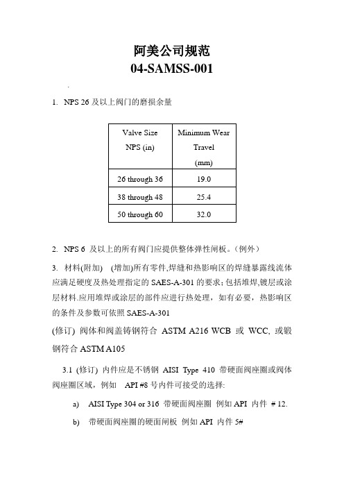
阿美公司规范04-SAMSS-001.1.NPS 26及以上阀门的磨损余量2.NPS 6 及以上的所有阀门应提供整体弹性闸板。
(例外)3.材料(附加) (增加)所有零件,焊缝和热影响区的焊缝暴露线流体应满足硬度及热处理指定的SAES-A-301的要求;包括堆焊,镀层或涂层材料.应用堆焊或涂层的部件应进行热处理,如有必要,热影响区的条件及参数可依照SAES-A-301(修订) 阀体和阀盖铸钢符合ASTM A216 WCB 或WCC, 或锻钢符合ASTM A1053.1(修订) 内件应是不锈钢AISI Type 410 带硬面阀座圈或阀体阀座圈区域,例如API #8号内件可接受的选择:a)AISI Type 304 or 316 带硬面阀座圈例如API 内件# 12.b)带硬面阀座圈的硬面闸板例如API 内件5#4.低温介质(-45 to -18°C)4.1内件须为不锈钢AISI Type 304 或316. 阀座圈须为硬面加司太立#6或等同(API STD 600 内件# 12).5.填料(附加)5.1 碳氢化合物介质下阀杆填料应是由含碳99% 的端环(John Crane - 1625G 或等同)和石墨中间环(John Crane - 237 或等同) 两种编织石墨丝组成的混合填料6.-101 to -45°C超低温介质(附加–仅指定时适用)6.1-101 to -45°C超低温介质阀门的附加a) 阀门应完全由不锈钢AISI Type 304 或316制造. 阀座圈须为硬面加司太立#6或等同(API STD 600 内件# 12).b) 体盖螺栓连接, 压盖螺栓, 压盖螺栓定位器及阀盖到支架的螺栓连接应为奥氏体不锈钢ASTM A320系列. 相应的螺母应为ASTM A194 8级系列c) (附加) 碳氢化合物介质下阀杆填料应是由含碳99% 的端环(John Crane - 1625G 或等同)和石墨中间环(John Crane - 237 或等同) 两种编织石墨丝组成的混合填料d) 泄压关闭零件的回流边上需钻3-5 mm的小孔. 阀体上应清晰标记流向.e) 泄压关闭零件的回流边上需钻3-5 mm的小孔. 阀体上应清晰标记流向.04-SAMSS-0351.水线要求1.1钢制光滑式密封面法兰垫片的接触面全,需要机械光面精整, 完成射程3.2到6.4微米2.排水管,通风口和阀体其他配件(钢阀)2.1 所有排泄阀门及相关管道零件抗耐腐蚀至少相当于内件材料,最低标准为AISI 316L SS3.材质3.1 当对焊连接阀门用碳钢和最低屈服强度289 MPa (42,000psi)或更高,最高碳含量不得超过0.26%.对于编织阀门,这种限制仅适用于端口。
AESJ002 Technically Acceptable Instrument沙特阿美仪表规范
Engineering StandardSAES-J-002 29 February, 2004 Technically Acceptable InstrumentInstrumentation Standards Committee MembersAl-Awami. L.H., ChairmanAl-Khalifa, A.H.Alqaffas, S.A.Al-Shiha, A.M.Fadley, G.L.Falkenberg, A.R.George, N.A.Hartman, R.A.Hazelwood, W.P.Khan, M.A.Mahmood, B.Trembley, R.J.Saudi Aramco DeskTop StandardsTable of Contents1 Scope (2)2 Conflicts and Deviations (2)3 References (2)4 General (4)5 Application (5)6 Explanatory Notes (5)7 Technically Acceptable Instruments (6)Previous Issue: 31 December, 2003 Next Planned Update: 1 March, 2006Next Planned Update: 1 March, 2006 Technically Acceptable Instruments 1 ScopeThis Standard lists, by category, instrument Manufacturers whose products have been found, after technical evaluation, to be technically acceptable for use in Saudi Aramco installations. It does not list all instruments that may be technically acceptable for use by Saudi Aramco. It lists only those that have undergone, and passed, Saudi Aramco technical evaluation. This Standard does not apply to purchasing procedures associated with instrument materials for replenishment of SAMS stock.2 Conflicts and Deviations2.1 Any conflicts between this standard and other applicable Saudi Aramco EngineeringStandards (SAESs), Materials System Specifications (SAMSSs), Standard Drawings(SASDs), or industry standards, codes, and forms shall be resolved in writing by theCompany or Buyer Representative through the Manager, Process & Control SystemsDepartment, Saudi Aramco, Dhahran.2.2 Direct all requests to deviate from this standard in writing to the Company or BuyerRepresentative, who shall follow internal company procedure SAEP-302 and forward suchrequests to the Manager, Process & Control Systems Department, Saudi Aramco, Dhahran.3 ReferencesThe selection of material and equipment, and the design, construction, maintenance, and repair of equipment and facilities covered by this standard shall comply with the latest edition of the references listed below, unless otherwise noted.Saudi Aramco ReferencesSaudi Aramco Engineering ProcedureSAEP-302 Instructions for Obtaining a Waiver of a Mandatory SaudiAramco Engineering RequirementSaudi Aramco Engineering StandardsSAES-J-001 Instrumentation Numerical IndexSAES-J-003 Basic Design CriteriaSAES-J-200 PressureSAES-J-400 TemperatureSAES-J-502 Analyzer SheltersSaudi Aramco Materials System Specifications34-SAMSS-117 Turbine Flow Meters34-SAMSS-118 Positive Displacement Meters34-SAMSS-318 Automatic Tank Gauging Equipment34-SAMSS-511 ChromatographsNext Planned Update: 1 March, 2006 Technically Acceptable Instruments34-SAMSS-512 Oxygen Analyzers34-SAMSS-514 Combustible Gas and Hydrogen Sulphide Monitors34-SAMSS-515 Moisture Analyzers34-SAMSS-517 Density Meters34-SAMSS-611 Safety Relief Valves Conventional and Balanced Types34-SAMSS-619 Burner Management Systems for Watertube Boilers34-SAMSS-621 ESD Systems - Hard-Wired - Solid-State(Non-Programmable)34-SAMSS-622 ESD Systems - Electromagnetic Relay34-SAMSS-623 Programmable Controller Based ESD Systems34-SAMSS-625 Vibration, Axial Position and Bearing TemperatureMonitoring Systems34-SAMSS-634 Local ZV Shutdown Cabinets and Smart ZV Systems34-SAMSS-711 Control Valves - General Services34-SAMSS-716 Pneumatic Actuators On-Off Service34-SAMSS-717 Hydraulic Valve Actuators34-SAMSS-718 Electric Motor Operated Valve Actuators34-SAMSS-815 Annunciators34-SAMSS-820 Instrument Control Cabinets - Indoor34-SAMSS-821 Instrument Control Cabinets - Outdoor34-SAMSS-830 Programmable Logic Controller34-SAMSS-831 Instrumentation for Packaged Units34-SAMSS-913 Instrumentation and Thermocouple CableSaudi Aramco Standard DrawingsAE-036014 Pole SettingAB-036019 Thermowell Assembly and DetailAC-036413 Orifice Flange Assembly, Raised FaceAB-036414 Orifice Flange Assembly, Ring JointSaudi Aramco Library DrawingDA-950065 Local Shutdown Cabinet with Partial Stroke Test DoubleActing ActuatorDB-950129 Sht 1 & 2 Local Shutdown Cabinet, Conventional DoubleActing/Spring Return ActuatorsSaudi Aramco Instrument Specification SheetsNext Planned Update: 1 March, 2006 Technically Acceptable InstrumentsForm 8020-415-ENG Thermocouple (T/C) AssemblyForm 8020-416-ENG Resistance Temperature Detector (RTD)Form 8020-418-ENG Thermowell4 General4.1 This Standard is intended to provide guidance to requisition originators and othersresponsible for the development and evaluation of bids for Saudi Aramco's instrumentationrequirements. The products listed below have been identified by Saudi Aramco as technicallyacceptable based on quality in relation to the state of the art, reliability, compatibility withexisting Saudi Aramco equipment and systems, familiarity with the product among SaudiAramco personnel, and, where appropriate, availability of local representatives for technicalassistance and maintenance. Although the instruments are listed by reference to their primaryManufacturers, an identical instrument manufactured by a licensee of a listed Manufacturer isalso technically acceptable.4.2 It is intended that all sources of instrumentation purchase come from the technicallyacceptable instrument manufacturers listed herein. All technically acceptable manufacturers'facilities shall be surveyed and approved by Vendor Inspection. All 9COM categories will bemaintained with an adequate number of technically acceptable instrument manufacturers.Changes to this standard shall be documented and approved in writing by the GeneralSupervisor, Process Instrumentation Division, Process & Control Systems Department, SaudiAramco.4.3 For any instrumentation purchases from manufacturers that are not listed in this standard, arequest for technical evaluation shall be submitted in writing to the General Supervisor,Process Instrumentation Division, P&CSD. The Instrumentation Unit/PID/P&CSD willevaluate the subject instrument product for technical acceptability, and shall inform therequestor in writing of the result. Only after the instrument has been identified as technicallyacceptable, and the manufacturer's facility approved by Vendor Inspection, can the purchaseorder be placed. These instrument products may or may not be added to the technicallyacceptable manufacturer's list.4.4 Some special instrumentation products are identified as 'simple commodities' or 'engineeredsystems'. See section 6 below for the special rules governing technical acceptability andselection of these products.5 ApplicationRequisition originators shall procure instrumentation products from the Manufacturers listed in this standard. When purchase from a Manufacturer not listed in this Standard is contemplated, approval per paragraph 4.3 shall be requested in writing from the General Supervisor, Process Instrumentation Division, Process & Control Systems Department, Saudi Aramco, Dhahran.6 Explanatory NotesThe following notes explain the use of Section 7, Technically Acceptable Instruments.Next Planned Update: 1 March, 2006 Technically Acceptable Instruments6.1 The number preceding each category title identifies the Standard (SAES), Specification(SAMSS) or Instrument Specification Sheet (ISS Form) associated with that type ofinstrument as listed in SAES-J-001 Instrumentation Numerical Index.6.2 The phrase "Pending Technical Evaluation" following a category heading means thattechnical evaluations of products in that category have not been performed. For theseproducts quotations may be requested from any qualified source. The procedures describedin paragraph 4.3 apply.6.3 The phrase "Not Recommended" following a category heading means that for technicalreasons, Saudi Aramco does not recommend use of that type of instrument. Use of thesedevices for evaluation and developmental applications requires prior written approval by theGeneral Supervisor, Process Instrumentation Division, Process & Control SystemsDepartment, Saudi Aramco, Dhahran. Normally, optional listed technically acceptableinstruments are available.6.4 For various simple commodities, the following note may be referenced in the list oftechnically acceptable instruments. This note shall apply only to those categories in which itis referenced.Commentary Note:The list of Manufacturers in this category is for guidance only. This simplecommodity may be purchased from any qualified source that can comply with themandatory requirements that are listed in each category in which this note isreferenced. The selected vendor should have a valid QA/QC survey records and avalid SA vendor number. Verification of compliance shall be the responsibility ofthe requisition originator. No IU technical evaluation or approval is required.However, ESO will assist in such evaluations when requested to do so.6.5 For various engineered systems the following note may be referenced in the list of technicallyacceptable instruments. This note shall apply only to those categories in which it isreferenced.Commentary Note:It is not practical to list sources of supply for this engineered system. Purchasemay be from any qualified source that can comply with the mandatory requirementsthat are listed in each category in which this note is referenced. Verification ofcompliance shall be the responsibility of the requisition originator. No IU technicalevaluation or approval is required. However, IU will assist in such evaluationswhen requested to do so.6.6 The approved vendors in this standard are listed by company name only. For approvedmanufacturing facilities for any of the listed vendors, refer to Purchasing Department SAPlist.7 Technically Acceptable Instruments100 FlowNext Planned Update: 1 March, 2006 Technically Acceptable Instruments111 Flow TransmittersD/P TransmittersSee Category 211 - Pressure and Differential Pressure Transmitters112 Flow Indicators112.1 Rotameters9COM - 6000002916 (CCC 340289) - Flowmeter: Variable Area(Rotameter)Emerson-Brooks Instrument DivisionABBKrohneSolartron Mobrey112.2 Flow Sight Glasses9COM - 6000002744 (CCC 340105)Ernst Gage Co.ABBClark-Reliance-Jacoby-Tarbox Corp.Tyco Flow Control-Penberthy112.3 D/P GaugesSee Category 217 - Differential Pressure Gauges113 Flow Switches113.1 D/P Switches – 9COM- 6000002830 (CCC 340198)See Category 213 - Pressure and Differential Pressure Switches113.2 Target Switches – 9COM- 6000002831 (CCC 340199)ITT-McDonnell and MillerSORMagnetrol114 Not Assigned115 Orifice Assemblies115.1 Orifice Plates and Flanges9COM- 6000002792 (CCC 340157) - Orifice Assembly: Plate, Flange,Sealing Ring9COM- 6000002793 (CCC 340158) - Orifice: PlateCommentary note in paragraph 6.4 applies.Mandatory requirements:Next Planned Update: 1 March, 2006 Technically Acceptable InstrumentsFor orifice plates - Std. Dwg. AE-036014For RF orifice flanges - Std. Dwg. AC-036413For RJ orifice flanges - Std. Dwg. AB-036414Some qualified Manufacturers are:Emerson-Daniel Div.FMC Energy SystemsVickery - Simms Division /FTI IndustriesSolartron ISA115.2 Meter Runs - Prefabricated Gas: 9COM- 6000002778(CCC 340143) Liquids 9COM- 6000002779 (CCC 340144)Emerson-Daniel Europe, Ltd.FMC Energy SystemsAlderley Systems, Ltd.Imtech Systems B.V.Solartron ISA (For skids up to 20MMSCF/Day)115.3 Orifice Fittings - Retractable Single Chamber9COM- 6000002792 (CCC 340157) - Orifice Assembly: Plate, Flange,Sealing RingEmerson-Daniel Div.FMC Energy Systems115.4 Orifice Fittings - Retractable Dual Chamber9COM- 6000002792 (CCC 3450157) - Orifice Assembly: Plate, Flange,Sealing RingEmerson-Daniel Div.FMC Energy Systems116 Venturi Tubes9COM- 6000007215 (CCC 340095) - Flow Meter: Venturi TubeEmerson-DanielABBFMC Energy SystemsSolartron ISA117 Turbine Meters9COM- 6000002775 (CCC 340140) - Flow Meter: Turbine Type;34-SAMSS-117Emerson-Daniel DivisionFMC Energy SystemsThermo MeasurementBarton Instrument Systems118 Liquid Positive Displacement MetersNext Planned Update: 1 March, 2006 Technically Acceptable Instruments 9COM- 6000002722 (CCC 340082) - Flow Meter: Positive Displacement Type;34-SAMSS-118Badger Meter, Inc.Bopp and Reuther MessTechnik GMBHFMC Energy SystemsEmerson- Daniel DivisionBarton Instrument Systems119 Liquid Meter Provers119.1 9COM- 6000002772 (CCC 340136) -Meter Prover: BI Directional &AccessoriesEmerson- Daniel DivisionFMC Energy SystemsAlderley119.2 9COM- 6000002773 (CCC 340137)- Meter Prover: Small VolumeProverCalibron SVP (Model S-15 piston type)Emerson- Daniel DivisionAlderley120 Pitot Tubes9COM- 6000002677 (CCC 340032) - Flow Meter: Annubar, Pitot TubeEmerson-Rosemount DivisionMeriam Instruments DivisionSolartron Mobrey121 Magnetic Flowmeters9COM- 6000002735 (CCC 340096) - Flow Meter: MagneticFoxboro Co.ABBBopp and Reuther MessTechnik GMBHSolartron MobreyEmerson-Brooks Instrument DivisionsYokogawa Electric CorporationEmerson-Rosemount Division122 Ultrasonic Flowmeters9COM- 6000002738 (CCC 340099) - Flow Meter: Ultrasonic122.1 Liquid ServiceKrohneGE PanametricsNext Planned Update: 1 March, 2006 Technically Acceptable Instruments122.2 Gas ServiceEmerson-Daniel DivisionInstrometGE Panametrics122.3 Flare Line ServiceGE PanametricsRoxar Flow Measurement AS (previously Fluenta)122.4 Multipath Ultrasonic Flow Meter9COM- 6000002777 (CCC 340142) - Flow Meter: Multipath UltrasonicEmerson-Daniel DivisionFMCInstrometKrohne123 Vortex Shedding Flowmeters9COM- 6000002739 (CCC 340100) - Flow Meter: Vortex SheddingABBFoxboroSolartron MobreyEmerson-Rosemount DivisionYokogawa Electric Corporation124 Restriction Orifices - Union TypePending Technical Evaluation125 Multi Phase FlowmetersCCC 340094 - Flow Meter: Multiphase9COM- 6000002917 (CCC 340290) - Flow Meter: MultiphaseCommentary note in paragraph 6.2 applies - other vendors "Pending TechnicalApproval"Approved vendors are:3-Phase Measurement ASAgar Corporation, IncorporatedRoxar Flow Measurement AS (previously Fluenta)126 Thermal Flowmeters9COM- 6000002736 (CCC 340097) - Flow Meter: ThermalThermo Systems, Inc.Emerson-Brooks Instruments DivisionFluid Components, Inc.Next Planned Update: 1 March, 2006 Technically Acceptable Instruments127 Flow Nozzles9COM- 6000002740 (CCC 340101) - Flow NozzleCrane Manufacturing, Inc.Emerson-Daniel DivisionVickery Simms/FTI Industries128Flowmeters - Coriolis Mass- 9COM- 6000002915 (CCC 340288)Commentary note in paragraph 6.2 applies - other vendors "Pending TechnicalApproval"Approved vendors are:Emerson-Micro Motion DivisionFoxboroFMC Energy Systems200 Pressure211 Pressure and Differential Pressure Transmitters9COM- 6000002850 (CCC 340219) - Transmitter: Flow9COM- 6000002851 (CCC 340220) - Transmitter: PressureFoxboro Co.Honeywell, Inc.Emerson-Rosemount DivisionABBSMAR International CorporationYokogawa Electric CorporationSiemens212 Pressure Gauges9COM- 6000002754 (CCC 340116) - Indicator: PressureCommentary note in paragraph 6.4 applies. Mandatory requirements are specified inSAES-J-200. Some qualified manufacturers are:Ametek, Inc. (U.S. Gauge Div.)BudenburgDresser Industries, Ashcroft Instrument Div.Dwyer Instruments, Inc. (Magnehelic)Dresser Al-Rushaid Valve & Instrument Co./Ashcroft213 Pressure and Differential Pressure Switches9COM- 6000002830 (CCC – 340198) - Switch: Differential Pressure9COM- 6000002834 (CCC – 340202) - Switch: PressureCrane-Barksdale ControlsCustom Controls Sensors, Inc.Dresser Al-Rushaid Valve & Instrument Co /AshcroftNext Planned Update: 1 March, 2006 Technically Acceptable Instruments Mercoid Corp.Barton Instrument SystemsUnited Electric ControlsSOR, Inc.214 Multivariable Transmitters9COM- 6000002926 (CCC 340299) - Transmitters MultivariableHoneywell, Inc.Emerson Rosemount Division215 Chemical Seals9COM– 6000002693 (CCC 340052) - Chemical SealAmetek, Inc.Dresser Industries, Instrument Div.Barton Instrument SystemsDresser Al-Rushaid Valve & Instrument Co /Ashcroft216 (Not Assigned)217 Differential Pressure Gauges9COM- 6000002749 (CCC 340111) - Indicator: Differential PressureBarton Instrument SystemsABBDwyer Instruments, Inc.Dresser Al-Rushaid Valve & Instrument Co /AshcroftMeriam Instrument300 Level311 D/P Level Transmitters9COM- 6000002849 (CCC 340218) - Transmitter: Level; Differential PressureFoxboro Co.Honeywell, Inc.Emerson- Rosemount DivisionABBYokogawa Electric CorporationSiemensSMAR International Corporation312 Level Gauge Glasses9COM- 6000002744 (CCC 340105) - Glass: Sight9COM- 6000002886 (CCC 340255) - Glass: Level GaugeSimco Engineers Ltd.Clark-Reliance-Jerguson Gage and Valve Co.Tyco Flow Control-Penberthy IncorporatedNext Planned Update: 1 March, 2006 Technically Acceptable Instruments313 Level Switches - Float and Displacer Type9COM- 6000002832 (CCC 340200) - Switch: LevelInternational, Inc.Mercoid CorporationK-TekSOR, Inc.314 Level Instruments - Displacer9COM- 6000002763 (CCC 340125) -Level Instruments Displacer Type:(Transmitters/Controllers; NA)Emerson- Fisher Control DivisionMasoneilan International, Inc.Dresser Al-Rushaid Valve & Instrument Co.FoxboroSolartronFMC InvalcoMagnetrol International, Inc.315 Level Instruments - Ultrasonic9COM- 6000002762 (CCC 340124) - Level Instrument: UltrasonicEndress and HauserDrexelbrook Engineering Co.Magnetrol International, Inc.Ohmart/Vega316 Level Instruments - Capacitance9COM- 6000002761 (CCC 340123) - Level Control: Capacitance TypeMagnetrol International, Inc.Solartron MobreyFMC InvalcoDrexelbrook Engineeering Co.Endress + Hauser317 Level Instruments - Nuclear Radiation9COM- 6000002764 (CCC 340126) - Level Instrument: Radiation TypeThermo MeasureTechOhmart/Vega Corp.Endress + Hauser318 Tank Gauging Equipment - Servo and Float9COM- 6000002838 (CCC 340206) - Tank Gauging Equipment: Automatic;34-SAMSS-318Enraf Delft InstrumentsL&J Technologies (Shand and Jurs)Next Planned Update: 1 March, 2006 Technically Acceptable Instruments Endress + Hauser319 Tank Gauging Equipment - Radar9COM- 6000002822 (CCC 340190) - Tank Gauging Equipment: Automatic; RadarTypeSaab RosemountEnraf Delft Instruments320 Time-Domain-Reflectometry Level Transmitters9COM- 6000007390 (CCC 340132) - Transmitter: Level; TDRMagnetrolKrohne (BM-100 only)K-Tek400 Temperature411 Temperature Transmitters9COM- 6000002852 (CCC 340221) - Transmitter: TemperatureFoxboro Co.Honeywell, Inc.Rosemount, Inc.ABBSMAR International CorporationYokogawa Electric CorporationSiemens412 Temperature Indicators9COM- 6000002756 (CCC 340118) - Indicator: TemperatureCommentary note in paragraph 6.4 applies. Mandatory requirements are specified inSAES-J-400. Some qualified manufacturers are:Ametek, Inc. (U.S. Gauge Div.)Dresser Industries, Ashcroft Instrument Div.ABBThermo Electric CompanyE2 Technology413 Temperature Switches - Mechanical9COM- 6000002835 (CCC 340203) - Switch: TemperatureCustom Contol Sensors, Inc.Kidde-Fenwal IncorporatedMercoid Corp.United Electric Co.SOR, Inc.Dresser Al-Rushaid Valve & Instrument Co /AshcroftNext Planned Update: 1 March, 2006 Technically Acceptable Instruments 414 (Not Assigned)415 Thermocouples9COM- 6000002888 (CCC 340258) - ThermocoupleCommentary note in paragraph 6.4 applies. Mandatory requirements are specified inForm 8020-415-ENG. Some qualified manufacturers are:Honeywell, Inc.Minco Products, Inc.Thermo Electric Co.ABBGay Engineering and Sales Co. (GAYESCO)United Electric ControlsConax Buffalo Technologies416 Resistance Temperature Detectors9COM- 6000002814 (CCC 340181) - Resistance Temperature Detector: (RTD)AssemblyCommentary note in paragraph 6.4 applies. Mandatory requirements are specified inForm 8020-416 ENG. Some qualified manufacturers are:Conax Buffalo TechnologiesMinco Products, Inc.Emerson-Rosemount DivisionThermo-Electric Co.ABB417 ThermistorsNot Recommended418 Thermowells9COM- 6000002845 (CCC 340214) - Thermowell:Standard Drawing AB-036019Commentary note in paragraph 6.4 applies. Mandatory requirements are specified inForm 8020-418 ENG. Some qualified manufacturers are:Dresser Industries, Ashcroft Instrument Div.Minco Products, Inc.Thermo Electric Co.ABBConax Buffalo TechnologiesDresser Al-Rushaid Valve & Instrument Co /Ashcroft419 Temperature Monitor Systems9COM- 6000002780 (CCC 340145): Monitor:34-SAMSS-625GE Power Systems-Bently Nevada Corp.Next Planned Update: 1 March, 2006 Technically Acceptable Instruments Rockwell Automation- Entek (IRD)Ametek-Rochester InstrumentThermo MeasurementSKF Condition Monitoring500 Analytical511 Chromatographs9COM- 6000002914 (CCC 340287) - Chromatograph: Process Gas or Liquid;34-SAMSS-511Siemens-Applied AutomationYokogawa Electric CorporationABB Process Analytics512 Oxygen Analyzers9COM- 6000002666 (CCC 340020) - Analyzer: Oxygen;34-SAMSS-512Ametek Process & Analytical InstrumentsServomexABBSiemens-Applied AutomationTeledyne Analytical InstrumentsEmerson- Rosemount Analytical DivisionGE PanametricsYokogawa Electric Corporation513 pH Analyzers9COM- 6000002667 (CCC 340022) - Analyzer: pHABBFoxboro Co.GLI InternationalHoriba InstrumentsEmerson - Rosemount Analytical DivisionYokogawa Electric Corporation514 Hydrogen Sulfide Monitors9COM- 6000002786 (CCC 340151) - Monitor: Hydrogen Sulfide in Air;34-SAMSS-514General MonitorsDetector ElectronicsDetcon, Inc.515 Trace Moisture Analyzers9COM- 6000002664 (CCC 340018) - Analyzer: Moisture;34-SAMSS-515Next Planned Update: 1 March, 2006 Technically Acceptable Instruments GE PanametricsAlpha Moisture SystemsShaw Moisture MetersAmetek Process & Analytical Instruments516 Analyzer Shelters9COM- 6000002898 (CCC 340270) - Analyzer Building, SAES-J-502ABB PastechSiemens Applied Automation517 Density Meters - Gas and Liquid9COM- 6000002720 (CCC 340080) - Density Meter: Gas and Liquid Service;34-SAMSS-517Thermo Measurement-SarasotaSolartron MobreyYokogawa Electric Corporation518 Gravitometers9COM- 6000002746 (CCC 340107) - GravitometerThermo Measurement-SarasotaSolartron Mobrey519 (Not Assigned)520 BS&W Analyzers9COM- 6000002655 (CCC 340008) - Analyzer: Bottom Sediment and WaterThermo MeasurementFMC-InvalcoHalliburton Energy ServicesAgar Corporation521 Chlorine Analyzers and Chlorinators9COM- 6000002658 (CCC 340011) - Analyzer: ChlorineABBEmerson-Rosemount AnalyticalYokogawa Electric CorporationGLI International522 Combustible Gas Monitors9COM- 6000002782 (CCC 340147) - Monitor: Combustible Gas9COM- 6000002787 (CCC 340152) - Monitor: Open Path Combustible Gas;34-SAMSS-514General Monitors, Inc.Detector ElectronicsNext Planned Update: 1 March, 2006 Technically Acceptable Instruments Detcon, Inc.523 Conductivity Analyzers9COM- 6000002660 (CCC 340013) - Analyzer: ConductivityEmerson-Rosemount AnalyticalGLI InternationalYokogawa Electric CorporationHoribaABB530 Process Color Analyzers9COM- 6000002659 (CCC 340012) - Analyzer: ColorHoribaABBAmetekMetrisa, Inc.610 Surge relief Valves, 9COM- 6000002896 (CCC 340267)610.1 Gas Loaded Surge Relief ValvesEmerson-Daniel DivisionSPX-Daniel Valve Company610.2 Pilot Operated Surge Relief ValvesEmerson-Daniel DivisionSPX-Daniel Valve CompanyControl Component, Inc.611 Safety Relief Valves - Flanged Conventional and Balanced9COM- 6000002869 (CCC 340238) - Valve: Safety Relief, Flanged Conventionaland Balanced Bellows Type; 34-SAMSS-611Tyco-Anderson GreenwoodDresser Industries (Consolidated)Dresser Al-Rushaid Valve & Instrument Co.Tyco- Safety Systems UKFarris Engineering612 Safety Relief Valves Pilot Operated9COM- 6000002868 (CCC 340237) - Valve: Safety Relief; Pilot Type612.1 For Processing PlantsTyco-Anderson GreenwoodDresser Industries (Consolidated)Dresser AL-Rushaid Valve & Instrument Co.Next Planned Update: 1 March, 2006 Technically Acceptable InstrumentsTyco- Safety Systems UKFarris Engineering612.2 For Storage Tanks and SpheroidsTyco – Whessoe (UK Factory)Tyco – Varec (USA Factory)Tyco-Anderson-Greenwood Crosby613 Vent Valves9COM- 6000002867 (CCC 340236) - Valve: Pressure Vacuum VentFor Pressure and Vacuum TanksTyco-Anderson-GreenwoodL&J Technology Co. (Shand & Jurs)Tyco – Whessoe (UK Factory)Tyco – Varec (USA Factory)614 Rupture Discs9COM- 6000002815 (CCC 340182) - Rupture Disc AssemblyBS&B Safety Systems, Inc.Fike Metal Products Corp.615 Flame Arrestors9COM- 6000002679 (CCC 340034) - Arrestor: FlameL&J Technologies (Shand and Jurs)Tyco – Varec616 Check Valve (Gauge Glasses)9COM- 6000002680 (CCC 340035)- Valve: Backflow Preventer9COM- 6000002854 (CCC 340223) - Valve: Check; Level Gauge Glass; FlowShut-OffClark-Reliance-Jerguson Gage and Valve Co.Tyco Flow Control-Penberthy IncorporatedSimco Engineers617 Flame Monitoring Systems9COM- 6000002732 (CCC 340092) - Flame Monitoring;34-SAMSS-619Fire EyeForney CorporationHoneywell, Inc.Hamworthy Combustion EngineeringABB618 Fire Detection Systems DeletedNext Planned Update: 1 March, 2006 Technically Acceptable Instruments619 Burner Management Systems for Watertube BoilersSee Category 623 ESD Systems for acceptable hardware vendors.620 Purge Systems Deleted621 ESD Solid State Logic Systems9COM- 6000002725 (CCC 340085) - Emergency Shutdown System: Solid StateLogic; 34-SAMSS-621Commentary note in paragraph 6.2 applies - other vendors pending technicalapprovalHIMA (Planar4 System)Yokogawa [Prosafe-DSP (SLS) System]622 ESD Relay Systems9COM- 6000002724 (CCC 340084) - Emergency Shutdown System: Relay;34-SAMSS-622Commentary note in paragraph 6.2 applies - other vendors pending technicalapprovalSilvertech623 ESD Programmable Controller Systems9COM- 6000002723(CCC 340083) - Emergency ShutdownProgrammable Logic Controller; 34-SAMSS-623Triconex Corporation (Tricon Versions 8&9)ICS Triplex (Regent, Regent Plus+ &Trusted)624 Speed Sensors (RPM)9COM- 6000002820 (CCC 340187) - Sensor: SpeedAI-TEK (Previously Airpax)GE Power Systems-Bently Nevada Corp.Woodward GovernorSKF Condition MonitoringRockwell Automation- Entek (IRD)625 Vibration Monitors - Noncontacting Type9COM- 6000002796 (CCC 340162) - Vibration MonitoringNon-Contacting Vibration and Axial Position; 34-SAMSS-625GE Power Systems-Bently Nevada Corp.Rockwell Automation- Entek (IRD)Bruel and KjaerSKF Condition Monitoring627 Shutdown Cabinets - Local, Pneumatic (Deleted)。
沙特阿美工程规程SAEP-22 Tank Calibration Requirements
Previous Issue: 28 April 2009 Next Planned Update: 22 May 2016Revised paragraphs are indicated in the right marginPage 1 of 15Primary contact: Maatoug, Maatoug A on 966-3- 8747960Engineering ProcedureSAEP-2222 May 2011Tank Calibration RequirementsDocument Responsibility: Custody Measurement Standards CommitteeSaudi Aramco DeskTop StandardsTable of Contents1 Scope............................................................2 2 Conflicts and Deviations................................ 23 Applicable Documents................................... 24 Definitions and Acronyms.............................. 35 Instructions.................................................... 56 Responsibilities.............................................. 87 Activity Matrix.............................................. 10 Attachment I – Required Information on the Tank Capacity Table................. 12 Attachment II – Qualifications of theThird Party Inspection Agency (15)Next Planned Update: 22 May 2016 Tank Calibration Requirements 1 ScopeThis procedure establishes the instructions and responsibilities for the calibration ofall Saudi Aramco royalty/custody tank gauging applications. This procedure is alsoapplicable to the inventory tanks that have the potential to be used for custody orroyalty measurement applications in case of the metering system failures. Organizations for which responsibilities are specified include, but are not limited to:∙The Proponent Organization∙Saudi Aramco Project Management Team (SAPMT)∙Process & Control Systems Department (P&CSD)2 Conflicts and Deviations2.1 Any conflicts between this procedure and other applicable Saudi AramcoEngineering Standards (SAESs), Materials System Specifications (SAMSSs),Standard Drawings (SASDs), or industry standards, codes, and forms shall beresolved in writing by the Manager, Process & Control Systems Department ofSaudi Aramco, Dhahran.2.2 Direct all requests to deviate from this procedure in writing in accordance withSAEP-302 to the Manager, Process & Control Systems Department of SaudiAramco, Dhahran.2.3 Direct all requests for interpretation of this procedure in writing to the Chairman,Custody Measurement Standards Committee for resolution. The Chairman,Custody Measurement Standards Committee shall be solely responsible fordetermining whether a proposed request meets the requirements of this procedure.3 Applicable DocumentsThe procedures covered by this document shall comply with the latest edition of thereferences listed below, unless otherwise noted:3.1 Saudi Aramco ReferenceSaudi Aramco Engineering ProcedureSAEP-302Instructions for Obtaining a Waiver of aMandatory Saudi Aramco EngineeringRequirementNext Planned Update: 22 May 2016 Tank Calibration Requirements3.2 Industry Codes and StandardsAmerican Petroleum Institute (API) Manual of Petroleum MeasurementStandards (MPMS)Chapter 2.2A Measurement and Calibration of UprightCylindrical Tanks by the Manual StrappingMethodChapter 2.2B Calibration of Upright Cylindrical Tanks usingthe Optical-Reference Line MethodChapter 2.2C Calibration of Upright Cylindrical Tanks usingthe Optical-Triangulation MethodChapter 2.2D Calibration of Upright Cylindrical Tanks usingthe Internal Electro-optical Distance RangingMethodChapter 2.2E Calibration of Horizontal Cylindrical Tanks-Part 1: Manual MethodsChapter 2.2F Calibration of Horizontal Cylindrical Tanks-Part 2: Internal Electro-Optical Distance-Ranging MethodStandard 2552 Method for Measurement and Calibration ofSpheres and SpheroidsStandard 2555 Liquid Calibration of Tanks4 Definitions and Acronyms4.1 DefinitionsApprove: Review and formal acceptance characterized by the signature of thefinal authorizing individual or organization.Capacity Table: A table often referred to as a tank capacity table or calibrationtable, showing the capacities of or volumes in a tank for various liquid levelsmeasured from the reference gauge point.Critical Zone: The region between initial and complete flotation of a floatingroof.Custody Transfer Measurement: A specialized form of measurement thatprovides quantity and quality information used for the physical and fiscaldocumentation of a change in ownership and/or responsibility of hydrocarboncommodities. This includes measurement of hydrocarbon liquid movementsNext Planned Update: 22 May 2016 Tank Calibration Requirements(deliveries or receipts) between Saudi Aramco and its customers, suppliers, jointventures and transport contractors including VELA ships.Customer: The party that takes ownership or responsibility of a hydrocarboncommodity from Saudi Aramco.Datum plate: A level metal plate located directly under the reference gaugepoint to provide a fixed contact surface from which liquid depth measurementcan be made.Deadwood: Deadwood refers to any object within the tank, including a floatingroof, which displaces liquid and reduces the capacity of the tank; also anypermanent appurtenances on the outside of the tank, such as cleanout boxes ormanholes, which increase the capacity of the tank. Deadwood is positive if itincreases tank capacity or negative if it decreases capacity.External Floating Roof: A cover over an open top storage tank consisting of adeck which rests upon the liquid being contained.Internal Floating Roof: A cover within a fixed roof tank which rests upon thepetroleum liquid being contained.Master Tape: A tape that is used for calibrating working tapes for tankmeasurements and is identified with a report of calibration at 68°F (20°C) and aspecific tension designated by the National Institute of Standards andTechnology (NIST) or an equivalent international standard organization.Recomputation: The process of re-generating the capacity tables through softcalculations, without repeating the field calibration measurements. It involves,simply, updating or revising the capacity table using previously established tankdiametersReference Gauge Height: The distance from the datum plate or tank bottom tothe reference gauge point.Royalty Measurement: A specialized form of measurement that is used as thebasis for paying royalty to the Saudi Arabian Government.SAP: The Saudi Aramco main system for enterprise resource management.Spheres: A stationary liquid storage tank, supported on columns so that theentire tank shall be aboveground.Spheroid: A stationary liquid storage tank having a shell of double curvature.Any horizontal cross-section is a series of circular arcs.Next Planned Update: 22 May 2016 Tank Calibration Requirements Strapping: The measurement of the external circumference of a vertical orhorizontal cylindrical tank by stretching a steel tape around each course of thetank's plates and recording the measurement.Tank Calibration: The process of determining the capacity of a tank throughfield measurements.Third Party Inspection Agency: An independent inspection agency whosefunction is to conduct an unbiased inspection of certain systems, equipment,materials, etc., against a set of standards, guidelines or procedures. For purposesof this SAEP, the Third Party Inspector has particular knowledge of andexperience of conducting tank calibration in accordance with industry custodymeasurement standards and procedures.4.2 AbbreviationsAPI American Petroleum InstituteCMU Custody Measurement Unit of Process & Control SystemsDepartmentEODR Electro Optical Distance RangingORLM Optical Reference Line MethodMPMS Manual of Petroleum Measurement StandardsP&CSD Process & Control Systems DepartmentSA Saudi AramcoSAEP Saudi Aramco Engineering ProcedureSAES Saudi Aramco Engineering StandardSAMSS Saudi Aramco Material SpecificationSAP Systems Application ProgrammingSASD Saudi Aramco Engineering Standard Drawing5 Instructions5.1 GeneralThis procedure shall be used in conjunction with existing international standardsand is not intended to replace the standards referred to in Section 3 above.The reference temperature for all tank capacity tables shall be 60°F forRefineries, Terminals, Gas Plants and 15°C for Distribution Operations.Next Planned Update: 22 May 2016 Tank Calibration Requirements5.2 Calibration/Re-calibration FrequenciesAll new tanks/vessels used for custody transfer measurement must undergocalibration prior to being put in service.All tanks/vessels must be recalibrated in conjunction with Testing andInspection (T&I), or when a major repair is don for tank bottom.The upright cylindrical tank shall be recalibrated in accordance within volume detected to invoke this appendix requirement.5.3 Precalibration PreparationsPrior to calibration, the upright cylindrical tanks, horizontal tanks, spheres andspheroids must have been filled to 95% of their design operating capacity for aminimum period of 24 hours with a liquid at least as dense as the product theywill normally store.Commentary Note:This requirement is considered met if the tank/vessel has been already hydro-tested.5.4 Recomputation RequirementsThe capacity table of horizontal tanks, spheres and spheroids must berecomputed if variation in product operating temperatures and temperatureassumed during calibration is greater than 11°C (20°F).Commentary Note:Variations in the product's calibration specific gravity and operating specificgravity greater than 20% will require a recomputation of the table, due to thehydrostatic head effect expansion on tanks/vessels.Floating roof correction table requires recomputation when any variation in theroof's weight, due to repairs or modifications, results in a change in the roofdeadweight that altered the tank predetermined volume by 0.02% or more.Commentary Note:While recalibration involves reestablishing tank diameters through standardcalibration methods and developing new tank capacity tables for custody andnon-custody transfers, recomputation, involves simply updating or revising thecapacity table using previously established tank diameters.Next Planned Update: 22 May 2016 Tank Calibration Requirements5.5 Acceptable Calibration TechnologiesFollowing is a list of the calibration technologies acceptable for tank/vesselcalibrations along with the reference standard the methods' implementationshould comply to. The methods are arranged in the order of priority, based onthe most efficient means of calibration for a given set of conditions.(1) Internal Electro Optical Distance Ranging Method (EODR),API Chapter 2.2D(2) Internal Electro Optical Distance Ranging Method (EODR),API Chapter 2.2F(3) Optical Reference Line Method (ORLM), API Chapter 2.2B(4) Manual Strapping Method(Strapping), API Chapter 2.2A(5) Optical Triangulation Method, API Chapter 2.2C(6) Manual Methods, API Chapter 2.2E(7) Liquid Calibration, API 2555(8) Method for Measurement and Calibration of Spheres and Spheroids,API STD 2552Commentary Note:All these methods essentially provide alternate techniques for measuring tankdiameters. While manual strapping is limited to external calibrations, theremaining methods can be used either externally or internally.5.6 Technology Selection Guidelinesa. The application of the EODR shall be limited to tanks/vessels that aregreater than 5 meters in diameter.b. The application of liquid calibration shall be limited to tanks/vessels thatare smaller than 5 meters in diameter.c. If a tank/vessel is insulated, it should be calibrated internally.d. External and internal EODR shall be used for all tanks/vessels that aregreater than 5 meters in diameter with no insulation.e. Either Internal or external ORLM shall be used for floating roof tanks.f. External ORLM can be used for fixed roof tanks with no insulation andhaving not more than a single wind girder.g. If the tank has multiple external wind girders, it should be calibrated eitherby external/internal EODR or internal ORLM.Next Planned Update: 22 May 2016 Tank Calibration Requirementsh.bottom elevations shall be sighted along radii every 45 degrees. Alongthese radii, elevations should be obtained at equally spaced intervals notmore than 10 feet (3 meters) from the tank's center to its shell. Liquidcalibration method is permitted to be used whenever the tank containsirregular shaped deadwood (e.g., steam coils, etc.).i. Spheres and spheroids shall be calibrated in accordance with API STD2552, Method for Measurement and Calibration of Spheres and Spheroids.6 ResponsibilitiesThe Saudi Aramco organizations with tank/vessels calibration responsibilities shallensure that their personnel become familiar with this SAEP.6.1 Saudi Aramco Project Management Team (SAPMT)a. Initiate calibration request for new tanks/vessels,b. Inform CMU of the calibration of new tanks only if is used for royaltytransfer,c. Request list of Approved Third Party Inspection Agencies,d. Contract tank calibrations to an approved Third Party Inspection Agency,e. Inform the Proponent to witness the calibration process,f. Obtain the capacity tables from the Third Party Inspection Agency,g. Request CMU's review for capacity tables of new royalty tanks,h. Provide two hardcopy and two electronic tables in US Customary unitsand/or (based on application requirement) SI units of the final approvedcalibration calculation and the capacity table to the Proponent.i. Close the activity.6.2 The Proponent Organizationa. Initiate requests for in-service tanks/vessels per the frequencyrequirements set forth in Section 5.2 above,b. Inform CMU of the calibration of new tanks if it is used for royaltytransfer applications,c. Request list of the approved Third Party Inspection Agencies,d. Contract tank calibrations to an approved Third Party Inspection Agency,e. Provide the operating data (operating temperature, density at operatingtemperature, operating pressure) to the Third Party Inspection Agency,Next Planned Update: 22 May 2016 Tank Calibration Requirementsf. Ensure the equipment used has been calibrated and has valid certificatesthat are traceable to National Institute of Standard and Technology (NIST)or other approved standards organization,g. Witness the field calibration process and ensure that the Third PartyInspection Agency is performing the tank/vessel calibration calculations inaccordance API MPMS Chapter 2.2A and API STD 2552, including, butnot limited to, the following capacity table correction factors,i. master tape corrections.ii. working tape correction.iii. tape rise correction.iv. tank shell temperature expansion correction.v. hydrostatic head effect correction.vi. tilt correction.vii. floating roof gravity adjustment.h. Consult with CMU if a technical inquiry about the calibration and/ordocumentation process cannot be resolved internally,i. Review the draft calibration calculations,j. Review the produced capacity tables and make sure they comply with the requirements in Attachment I,k. Submit the capacity tables for the calibration of the new tanks to theSAPMT,l. Submit initial capacity tables of new royalty tanks only to CMU forreview.m. Maintain two hardcopy and two electronic tables in US Customary units and/or (based on application requirement) SI units of the final approvedcalibration calculation and the capacity table to the proponent,n. Update the SAP Tank Gauging System with the new approved capacitytable, if applicable,o. Inform the SAPMT of the completion of the tank calibration,p. Commission the tank,q. Close the activity.6.3 Process & Control Systems Department (P&CSD)The Process & Control Systems Department/Custody Measurement Unit (CMU)is responsible for providing technical assistance to the Proponent(s) on mattersNext Planned Update: 22 May 2016 Tank Calibration Requirements pertaining to tank calibrations. Specific responsibilities of CMU aresummarized below:a. Review the qualifications of the Third Party Inspection Agencies and makesure they meet all of the requirements detailed in Attachment II.b. Maintain the list of Approved Third Party Inspection Agencies.c. Submit the list of the Approved Third Party Inspection Agencies to theSAPMT and the Proponent upon request.d. Upon request from the proponent, provide consultation if a technicalinquiry about the calibration and/or documentation process cannot beresolved internally.e. Review initial capacity tables of new royalty tanks only.7 Activity MatrixThe following matrix summarizes the general sequence of activities and corresponding responsible organizations for calibrating tanks. Detailed requirements for eachorganization are specified in Section 6.Next Planned Update: 22 May 2016 Tank Calibration RequirementsNote:(1) SAPMT initiates calibration request for new tanks/vessels. The Proponent initiates calibrationrequest for tanks/vessels in-service per the frequency requirements set forth in Section 5 above.For BI-1900, the proponent will assume the responsibilities of SAPMT.Revision Summary22 May 2011 Revised the "Next Planned Update". Reaffirmed the contents of the document, and reissuedwith minor changes.Next Planned Update: 22 May 2016 Tank Calibration Requirements Attachment I – Required Information on the Tank Capacity TableThe final capacity table should contain the following minimum documentation details:1. Tank Identificationa. The site or installation tank numberb. Location Titled with “Saudi Arabian Oil Company”c. The type of tank in serviced. The name of the plant, owner or operatore. The name and address of the calibration authority or company which carriedout the calibration.2. Product InformationThe product name and density of the liquid stored in the tank when in service andused in the computation of the tank capacity tables.3. Operational Detailsa. The standard temperature (60°F for U.S. Customary, or 15°C for metrictables) for which the tank capacity table has been calculated.b. Operating temperature and pressurec. Table type (innage or ullage)4. Traceability and Tracking Detailsa. The date a new tank was first calibratedb. The date an old tank was recalibratedc. Calibration agent reference document numberd. The date the tank was recomputed, and the method used for recomputatione. The date of the calibration along with specific references to the methodadopted in calibrating the tank bottomf. Page numberg. Reference to the standard on which the calibration is basedh. The Third Party Inspection Agency shall sign and stamp each page of thecertificate.Next Planned Update: 22 May 2016 Tank Calibration Requirements5. Tank Dimensionsa. The nominal height and diameter of the tankb. Description of the tank bottom type, along with the method used todetermine the bottom volumec. Integrated deadwood, accurately accounted for as to location and volume,and included as an attachmentd. Note on capacity table that the volume below the striking plate is included inthe first measuremente. The shell height, is measured as the vertical distance between the bottom ofthe bottom angle and top of the top angle and measured near the referencegauge hatchf. Reference height measurement point locations shall be clearly identified ontank capacity tablesg. The height of the datum-points(s) with reference to the junction of the tankshell and bottom platingh. If an automatic gauging system is installed, the height of the gauge datumpoint with reference to the junction of the tank shell and bottom platingi. Maximum fill heightj. Safe fill height specified by the tank ownerk. The amount of tilt in shell height is measured and recorded.l. Height of the striking point (datum plate) from the tank bottom platem. The decimal (fraction) average volume for each strapping page.6. Floating Roof Informationa. The allowance for the roof is to be treated as deadwood and incorporated inthe tank capacity table directly, not as a separate attachmentb. The density of the liquid for which the roof has been calculated shall berecorded on the table directlyc. The apparent mass in air of the roof and accessoriesd. The displacement volume of the roof and the floating roof correction factormethod statemente. A defined level (Level A), with the distance above the dip point designatingwhere the roof is at restf. A defined level (Level B), with the distance when the roof is just fullyfloating in the lowest-density liquid to be contained in the tankNext Planned Update: 22 May 2016 Tank Calibration Requirementsg. The part of the capacity table between Level A and Level B is marked as“Not Accurate”h. Critical zones shall be identified within the tablei. The range where floating roof adjustment not to be performed.7. Tank Shell Correctiona. A shell temperature expansion factor table is to be developed in incrementsof 5°F or 3°C and included as an attachment to the capacity table for aspecific operating range.b. Include the equation for determining the shell temperature.Next Planned Update: 22 May 2016 Tank Calibration Requirements Attachment II – Qualifications of the Third Party Inspection AgencyThe Third Party Inspection Agency shall meet all of the following requirements:1. The agency has provided similar services for a minimum of 3 years. It shallsubmit a list of companies for which it has provided similar calibration servicesover the preceding 3 years.2. The agency's personnel performing the field measurements and calculations musthave a minimum of one year experience with the application of the APItank/vessel calibration standards. Experience shall be documented by submittal ofresume and verifiable work histories.3. The agency shall have written procedures which meet the requirements of APItank/vessel calibration standards. It shall submit the written procedures forreview.4. The agency shall have equipment as specified in API MPMS Chapter 2.2. It shallsubmit a list of the equipment it intends to use along with corresponding validcalibration certificates.5. The agency shall demonstrate it is ISO-certified and that it is activelyadministering a quality assurance program. It shall submit a copy of its ISOcertification and his quality assurance program details for review.6. The agency shall demonstrate that it is capable of performing the tank/vesselcalibration calculations. It shall provide a minimum of two samples of previouscalibration results, including field data and all calculations.7. The agency shall provide financial and insurance documentations as deemednecessary by the Contracting Unit to ensure he has adequate liability coverage fordamages done to Saudi Aramco facilities.。
沙特阿美工程规程SAEP-341 Equipment Life Cycle Cost Procedure

Previous Issue: 26 July 2009 Next Planned Update: 20 October 2017Page 1 of 14 Primary contact: Odan, Nabeel Mohammad on 966-3-8809506Engineering ProcedureSAEP-34120 October 2012 Equipment Life Cycle Cost Procedure Document Responsibility: Pumps, Seals & Mixers Standards CommitteeSaudi Aramco DeskTop StandardsTable of Contents1 Scope (2)2 Applicable Equipment Typesand Required LCC Data (2)3 Applicable Documents (3)4 Instructions (4)Appendix A – Calculation Methodsfor Life Cycle Cost Analysis (9)Next Planned Update: 20 October 2017 Equipment Life Cycle Cost Procedure1 ScopeThis procedure provides instructions for economically evaluating major equipmentpurchases with regards to their estimated total ownership cost (Life Cycle Cost) toSaudi Aramco over a twenty (20) years period. These costs include procurement andoperation cost (energy cost and quantifiable periodic maintenance) of the equipment.This procedure details the requirements for determining Life Cycle Costs (LCC) forpurchases of major equipment identified in Section 2. The applicable LCC analysisSpreadsheets provide a practical vehicle for performing the required calculations.2 Applicable Equipment Types and Required LCC DataNext Planned Update: 20 October 2017 Equipment Life Cycle Cost Procedure 3 Applicable Documents3.1 Saudi Aramco Materials System Specifications14-SAMSS-531Power Transformers17-SAMSS-502Induction Motors17-SAMSS-510Brushless Synchronous Generator17-SAMSS-520Synchronous Motors31-SAMSS-001Centrifugal Compressors31-SAMSS-004Centrifugal Pumps31-SAMSS-006Integrally Geared Centrifugal Compressor32-SAMSS-021Manufacture of Industrial Boilers32-SAMSS-029Manufacture of Fired Heaters3.2 Saudi Aramco Engineering StandardsSAES-F-001Design Criteria of Fired HeatersSAES-G-005Centrifugal PumpsSAES-K-402Centrifugal CompressorsSAES-P-113Large Electrical MotorsSAES-P-121Power Transformers3.3 Saudi Aramco Standards Data Sheet2741-ENG & Centrifugal Pump Data Sheet for2741-M-ENG Horizontal Pumps and Vertical In-line Pumps2748-ENG & Centrifugal Pump Data Sheet for2748-M-ENG Vertical Line Shaft Pumps8150-ENG & Packaged Integrally Geared Centrifugal8150-M-ENG Air Compressor Data SheetForm 9550-ENG Watertube Boiler Data Sheets (herein referred to asData Sheet)175-323700Manufacture of Fired Heaters3.4 Life Cycle Cost SpreadsheetsThe following spreadsheets are to be used in the analysis and are available in theForms section of the Engineering Standards website:LCC-001Centrifugal Pumps (31-SAMSS-004) *Next Planned Update: 20 October 2017 Equipment Life Cycle Cost ProcedureLCC-002Centrifugal Pump-Motor Trains (31-SAMSS-004)LCC-005Centrifugal Compressors (31-SAMSS-001) *LCC-006Centrifugal Compressor-Motor Trains(31-SAMSS-001)LCC-010Integrally Geared Centrifugal Compressor-MotorTrains (31-SAMSS-006)LCC-019Induction Motors (17-SAMSS-502) *LCC-020Synchronous Motors (17-SAMSS-520) *LCC-023Power Transformers (14-SAMSS-531)LCC-024Boilers (32-SAMSS-029)LCC-024A Dual Fuel Boilers (32-SAMSS-021)LCC-025Fired Heaters (32-SAMSS-029)LCC-025A Dual Fuel Fired Heaters (32-SAMSS-029)* These spreadsheets are to be used when buying stand-alone pumps,compressors, or motors. For equipment trains (i.e., motor driven pump train,etc.), the train work sheets are to be used.4 Instructions4.1 SAPMT Submittal of Project Equipment ListsSaudi Aramco Project Management Team (SAPMT) shall prepare and includethe following items in the project proposal documents:4.1.1 A list of the Project's equipment items that are covered by the aboveSAMSS.4.1.2 A list of equipment items subject to LCC analysis. This list is to beincluded in schedule G of the contract. A copy is to be sent toEstimating Services Division (ESD/PMOD) so that they includeadditional allowances in the ER estimate to cover the differential inequipment cost due to LCC analysis.4.1.3 A list of equipment items with long lead-time delivery that may requireexpedited SAPMT bid development.4.1.4 A list of the latest applicable energy costs obtained from FPD.Next Planned Update: 20 October 2017 Equipment Life Cycle Cost Procedure4.2 Equipment Requiring SAPMT Bid DevelopmentFor equipment requiring SAPMT bid development prior to contract award (longlead equipment), the following steps shall be implemented:4.2.1 Upon receipt of the equipment bids, SAPMT's technical evaluation shallensure that the bids contain the required data needed to perform LCCanalysis.4.2.2 SAPMT shall submit the bids technical data to CSD for review and shallhighlight the technical LCC data (i.e., power, efficiency, operatingfactor) that will be used in the LCC analysis.4.2.3 CSD shall review the technical bid data along with the LCC data elementsand provide comments, if any, to SAPMT within 10 working days.4.2.4 SAPMT shall perform the LCC analysis by utilizing the applicable LCCSpreadsheet (s) to determine the Life Cycle Cost for each acceptablevendor. Other quantifiable cost factors that may significantly impact theeconomic analysis (such as delivery dates) may be included in the LCCanalysis. Inclusions of supplementary cost factors require the priorapproval of the project manager and CSD's concurrence.4.2.5 SAPMT shall calculate the savings (S LCC) in life cycle cost according tothe following equation:S LCC = LCC LIB– LCC LV (1)where:LCC LV is the equipment life cycle cost of the vendor with the lowestoverall LCCLCC LIB is the life cycle cost of the vendor with the lowest initial bid4.2.6 Purchase Order (P/O) shall be placed with the vendor having the lowestLCC (LCC LV) if S LCC is equal to $25000 or 5% of the LIB whichever ishigher.4.2.7 After P/O placement, SAPMT shall submit a copy of the final LCCSpreadsheet(s) to Estimating Services Division (ESD/PMOD) forarchiving and to CSD for information.4.2.8 If Project Management awards to a vendor, a purchase order with apotential performance liability based on the provisions of the applicableSAMSS (penalty clause), and the purchase order is to be transferred(“novated”) to the successful LSTK contractor on the project, ProjectNext Planned Update: 20 October 2017 Equipment Life Cycle Cost Procedure Management and/or Purchasing must include provisions in the NovationAgreement that specifically describe the liability being assumed by thecontractor.4.2.9 The equipment shall be tested at the vendor facility for guaranteedefficiency if required by the applicable Saudi Aramco Materials SystemSpecification (SAMSS) and/or the Project Contract. If the equipmentdoes not meet the specified efficiency, and cannot be corrected withinthe test tolerance as specified in the SAMSS, a penalty shall be imposedon the supplier as defined in the SAMSS and the Purchase order.4.3 Equipment Not Requiring SAPMT Bid DevelopmentFor Contractor procured equipment (all non-long-lead time equipment) thefollowing steps shall be implemented:4.3.1 After evaluating the vendor submittals, the Contractor shall provide thebid technical data, required commercial data per schedule G, and theequipment site delivery date for each vendor to SAPMT for review.4.3.2 SAPMT shall review the information to determine if it contains all of therequired data needed to complete the LCC analysis and shall require theContractor to provide any missing or unacceptable data.4.3.3 SAPMT shall provide a copy of the bid technical data including the LCCdata elements (operating factor, efficiency at normal load point, etc.), toCSD for review.4.3.4 CSD shall review the technical bid data along with the LCC dataelements and provide comments to SAPMT within 10 working days.4.3.5 SAPMT shall perform the LCC analysis by utilizing the applicable LCCSpreadsheet(s) to determine the Life Cycle Cost for each acceptablevendor. Other quantifiable cost factors that may significantly impact theeconomic analysis (such as savings due to early delivery) may beconsidered for inclusion in the LCC analysis. Inclusions ofsupplementary cost factors require the prior approval of the projectmanager and CSD's concurrence.4.3.6 SAPMT shall calculate the savings (S LCC) in life cycle cost according tothe following equation:S LCC = LCC LIB– LCC LV(2)Next Planned Update: 20 October 2017 Equipment Life Cycle Cost Procedure where:LCC LV is the equipment life cycle cost of the vendor with the lowestoverall LCCLCC LIB is the life cycle cost of the vendor with the lowest initial bid4.3.7 SAPMT shall direct the contractor to place the Purchase Order (P/O)with the vendor having the lowest LCC (LCC LV) if S LCC is equal to105% or higher of the compensation to the LSTK Contractor (refer toparagraph 4.3.8).4.3.8 If the COMPANY directs the CONTRACTOR to purchase theequipment from any manufacturer technically qualified by theCONTRACTOR other than the CONTRACTOR's proposed source ofsupply, the COMPANY shall compensate the CONTRACTOR for anydifference between the total delivered equipment cost ofCONTRACTOR's proposed source of supply and that of the COMPANYdirected manufacturer.4.3.9 After P/O placement, SAPMT shall provide a copy of the final LCCSpreadsheet(s) to the Estimating Services Division (ESD/PMOD) forarchiving and to CSD for information.4.3.10 The equipment shall be tested at the vendor facility for guaranteedefficiency if required by the applicable Saudi Aramco Materials SystemSpecification (SAMSS) and/or the Project Contract. If the equipmentdoes not meet the specified efficiency, and cannot be corrected withinthe test tolerance as specified in the SAMSS, a penalty shall be imposedon the contractor as defined in the SAMSS and the Project Contract.4.4 All Direct Charge Purchases Requiring LCC AnalysisFor Direct Charge (D/C) procurement of equipment, the following steps shall beimplemented:4.4.1 The Proponent Requisition Originator shall develop the PurchaseRequisition (PR) or the Request for Quotation (RFQ) for the subjectequipment and forward it to Purchasing for bid development. If therequested equipment requires LCC analysis as specified in the applicableSAMSS, the Requisition shall clearly indicate the required LCC datawhich the bidders need to provide.4.4.2 Upon receipt of the PR or the RFQ, the Purchasing Buyer shall reviewthe indicated line items and specifications to determine if any of theNext Planned Update: 20 October 2017 Equipment Life Cycle Cost Procedure items require LCC analysis.4.4.3 Upon receipt of bids, the Buyer shall request the Proponent RequisitionOriginator to perform the technical evaluation.4.4.4 The Buyer shall obtain the latest applicable energy costs from FPD foruse in the LCC analysis.4.4.5 The Buyer shall perform the LCC analysis by utilizing the applicableLCC Spreadsheet(s) to determine the Life Cycle Cost for all technicallyand commercially acceptable vendors.4.4.6 The buyer shall calculate the savings (S LCC) in life cycle cost according tothe following equation:S LCC = LCC LIB– LCC LV(3)where:LCC LV is the equipment life cycle cost of the vendor with the lowestoverall LCC costLCC LIB is the life cycle cost of the vendor with the lowest initial bid4.4.7 Purchase Order (P/O) placement shall be with the vendor having thelowest LCC (LCC LV) if S LCC is equal to $25000 or 5% of the LIBwhichever is higher.4.4.8 If the equipment cost for the selected equipment is higher than the PR'sauthorized limit, the Requisition Originator (Proponent) shall initiate aChange Requisition to authorize these additional funds.4.4.9 After P/O placement, Buyer shall submit a copy of the final LCCSpreadsheet to Estimating Services Division (ESD/PMOD) for archivingand a copy to CSD for information.The equipment shall be tested at the vendor facility for guaranteedefficiency if required by the applicable Saudi Aramco MaterialsSpecification (SAMSS) and/or the Project Contract. If the equipmentdoes not meet the guaranteed efficiency, and cannot be corrected withinthe test tolerances allowed, a penalty shall be imposed upon the supplierin accordance with the terms and conditions specified in the applicablePurchase Order.Revision Summary13 October 2012 Major revision.Next Planned Update: 20 October 2017 Equipment Life Cycle Cost ProcedureAppendix A – Calculation Methods for Life Cycle Cost AnalysisThis section is included in this SAEP for clarification purpose only. The logic is already included in the Life Cycle Cost Spreadsheets.A.1 Centrifugal Pumps and Centrifugal CompressorsUnless otherwise approved by the Coordinator, Rotating Equipment Division,Consulting Services Department, the Life Cycle Cost (LCC) of the centrifugalpumps and centrifugal compressors is determined from the following formula:LCC = IC + OC (4)where:IC = Initial Cost, $ (Purchase order cost of all equipment being bought)OC = Present value of Operating power Cost, $, for operating period of20 years= P * EF * No. of units being boughtP = Equipment Power in kW, at normal flow rate for actual fluid.EF = Evaluation Factor ($/kW) will be shown on the data sheet and/or inthe quotation request= 11.56 * EC * AHEC = Energy Cost in $/kWhAH = Annual operating Hours= OF * 8760OF = Operating Factor= Number of Operating Units divided by the number of units beingbought.Next Planned Update: 20 October 2017 Equipment Life Cycle Cost ProcedureA.2 Electrical Motor Driven Centrifugal Pump, Electrical Motor Driven CentrifugalCompressor and Electrical Motor Driven Integrally Geared Compressor TrainsUnless otherwise approved by the Coordinator, Rotating Equipment Division,Consulting Services Department, the Life Cycle Cost (LCC) of the electricalmotor driven trains is determined from the following formula:LCC = IC + OC (5)where:IC = Initial Cost, $ (Purchase order cost of all trains being bought)OC = Present value of Operating power Cost, $, for operating period of20 years= P/(Em*EG) * EF * No. of trains being boughtP = Driven equipment Power in kW, at normal flow rate for actualfluid.Em = Motor Efficiency at normal operating load (decimal)EG = Gear Efficiency at normal operating load (decimal). If there is nogear, EG = 1EF = Evaluation Factor ($/kW) will be shown on the data sheet and/or inthe quotation request= 11.56 * EC * AHEC = Energy Cost in $/kWhAH = Annual operating Hours= OF * 8760OF = Operating Factor= Number of operating trains divided by the number of trains beingbought.Next Planned Update: 20 October 2017 Equipment Life Cycle Cost ProcedureA.3 Electrical MotorsUnless otherwise approved by the Coordinator, Electrical Systems MechanicalDivision, Consulting Services Department, the Life Cycle Cost (LCC) of theelectrical motors is determined from the following formula:LCC = IC + OC (6)where:IC = Initial Cost, $ (Purchase order cost of all motors being bought)OC = Present value of Operating power Cost, $, for operating period of20 years= RP * EF * No. of motors being boughtRP = Required Power in kW= P/EmP = Motor load in kW, at normal operating conditions.Em = Motor vendor's Guaranteed Efficiency at normal operating load(decimal)EF = Evaluation Factor ($/kW) will be shown on the data sheet and/or inthe quotation request= 11.56 * EC * AHEC = Energy Cost in $/kWhAH = Annual operating Hours= OF * 8760OF = Operating Factor= Number of operating motors divided by the number of motorsbeing bought.Next Planned Update: 20 October 2017 Equipment Life Cycle Cost ProcedureA.4 Life Cycle Cost Evaluation for Boilers and Fired HeatersUnless otherwise approved by the Coordinator, Mechanical & Civil EngineeringDivision, Consulting Services Department, the Life Cycle Cost (LCC) of theboilers and fired heaters is determined from the following formula:Single Fuel Services:LCC = IC + OC (7)where:IC = Initial Cost, $ (Purchase order cost of all units being bought)OC = Present value of Operating power Cost, $, for operating period of20 years= CF * EF * No. of units being boughtCF = Consumed Fuel (Heat Release) in MMBTU/hr= L/EFFL = Unit load (Duty) at normal condition (MMBTU/hr) provided in thedata sheet by the buyer.EFF = Unit Efficiency (decimal) at normal condition provided by vendor.EF = Evaluation Factor ($-hr / MMBTU) will be shown on the data sheetand/or in the quotation request= 11.56 * EC * AHEC = Energy Cost in $/MMBTUAH = Annual operating Hours= OF * 8760OF = Operating Factor= Number of operating units divided by the number of units beingbought. OF = 1 for process heaters since there is no standbyprocess heaters.Next Planned Update: 20 October 2017 Equipment Life Cycle Cost Procedure Dual Fuel Services:LCC = IC + OCx + OCy (8)where:IC = Initial Cost, $ (Purchase order cost of all units being bought)OCx = Present value of Operating power Cost, $, for operating period of20 years= CFx * EFx * No. of units being boughtOCy = Present value of Operating power Cost, $, for operating period of20 years= CFy * EFy * No. of units being boughtCFx = Consumed Fuel (Heat Release) in MMBTU/hr= Lx/EFFCFy = Consumed Fuel (Heat Release) in MMBTU/hr= Ly/EFFEFx = Evaluation Factor for fuel type x ($-hr / MMBTU) will be shownon the data sheet and/or in the quotation request= 11.56 * ECx * Tx / AHEFy = Evaluation Factor for fuel type y ($-hr / MMBTU) will be shownon the data sheet and/or in the quotation request= 11.56 * ECy * Ty / AHL = Unit load (Duty) at normal condition (MMBTU/hr) provided in thedata sheet by the buyer.EFF = Unit Efficiency (decimal) at normal condition provided by vendor.EC = Energy Cost in $/MMBTUAH = Annual operating Hours= OF * 8760Next Planned Update: 20 October 2017 Equipment Life Cycle Cost Procedure OF = Operating Factor= Number of Operating units divided by the number of units beingbought. OF = 1 for process heaters since there is no standbyprocess heatersNote:x & y are the types if fuel that will be provided in the data sheets by buyer.A.5 Power TransformersUnless otherwise approved by the Coordinator, Electrical Systems Division,Consulting Services Department, the Life Cycle Cost (LCC) of the powertransformers is determined from the following formula:LCC = IC + [No. of transformers being bought * (A*Li+B*Lc)] (9) where:IC = Initial Cost, $ (Purchase order cost of all transformers beingbought)A*Li = Present value of no-load loss cost in $, for operating period of20 yearsB*Lc =Present value of load loss cost in $, for operating period of 20 yearsA = No Load Loss Constant, $/kW= 11.56* E1*T1E1 = Energy Cost, $/kWhT1 = Annual operating Hours, 8760 hrLi = Manufacturer guaranteed no-load loss, kWB = Load Loss Constant, $/kW= 0.49 * ALc = Manufacturer guaranteed load loss, kWCommentary Note:The constant 11.56 is a present value factor based the formulaPV=[(1+i)n-1]/[i(1+i)n], where i is the discount rate (5.9%) expressed as adecimal number and n is the life of the motor (20 years).。
沙特阿美项目微型隧道工艺及施工管理

140
石油天然气学报
沙特阿美项目微型隧道工艺及施工管理
在发送井内顶进设备单元的作用下,将钻机和计划铺设的套管按顺序顶入,直至套管从接收井内顶出。 根据地质情况和套管材质不同,各套管连接处需采取对应方式进行密封。整个施工过程分为入场准备、 设备入场安装调试、掘进作业、顶进收尾四个阶段。
Figure 1. Schematic diagram of micro tunneling 图 1. 微型隧道穿越示意图
3.1. 作业时间管理
沙特阿美作业许可管理要求相对十分严格,穿越施工需要办理热作业和受限空间作业许可,由沙特 阿美许可管理人员发放的施工许可只允许工作日施工且时间范围在许可管理员的工作时间,加上现场遇 到的恶劣天气停工以及等待沙特阿美许可管理人员到现场检查后才允许发放许可的情况,与其他地区相
DOI: 10.12677/jogt.2020.424124
142
石油天然气学报
沙特阿美项目微型隧道工艺及施工管理
比,实际工作时间不足。 此外,由于穿越施工特殊性,除阿美公司许可外,如高速公路和铁路穿越还需要获得沙特政府相应
管理部门批准,有效期限一般都比较紧张。在日工作时长和工期受限的条件下,如何保证有效作业时间 就成为了需要面对的首要问题。
因此,项目部一方面与沙特阿美多次争取和沟通,获准在沙特阿美管线、站场等设施一定距离外允 许由经认证的承包商许可管理员开具内部许可进行作业,在这些区域时,采取清晨开工的方式适当延长 每天作业时间且不受周末限制;另一方面从管理上入手,在不得不等待沙特阿美许可时,先使用内部许 可完成设备开机调试等准备工作,保证拿到许可后即可立即开钻,保证掘进作业的有效时间。
Figure 2. Laser positioning system 图 2. 激光定位系统
- 1、下载文档前请自行甄别文档内容的完整性,平台不提供额外的编辑、内容补充、找答案等附加服务。
- 2、"仅部分预览"的文档,不可在线预览部分如存在完整性等问题,可反馈申请退款(可完整预览的文档不适用该条件!)。
- 3、如文档侵犯您的权益,请联系客服反馈,我们会尽快为您处理(人工客服工作时间:9:00-18:30)。
Previous Issue: 7 November 2006 Next Planned Update: 12 May 2017Page 1 of 11Primary contact: Nasri, Nadhir Ibrahim on 966-3-8809603Engineering ProcedureSAEP-35112 May 2012Bolted Flange Joints AssemblyDocument Responsibility: Piping Standards CommitteeSaudi Aramco DeskTop StandardsTable of Contents1 Scope.............................................................2 2 References..................................................... 23 Responsibilities.............................................. 24 Pre-Assembly Inspection............................... 35 Torquing......................................................... 46 Torquing Tools............................................... 47 Stud Bolt Tightening Procedure..................... 48 Stud Bolt Additional Tightening Procedure where Leaks OccurDuring Pressure Testing (5)Table-SAEP-351-01 – Friction Factors for Different Lubricants.................................. 6 Table-SAEP-351-02 – Torque Values for Low-Alloy Steel Bolting............................. 7 Table-SAEP-351-03 – Torque Values for Isolating Gaskets (PIKOTEK) on ASME B16.5 and ASME B16.47 Series A & B, Class 150 Through Class 2500 Flanges....................................... 8 Figure SAEP-351-01 – Stud Bolt Tightening Sequence (4 to 32 Bolts)............................... 9 Figure SAEP-351-02 – Stud Bolt Numbering (36 to 68 Bolts)............................................. 10 Table-SAEP-351-04 – Cross-Pattern Tightening Sequence (36 to 68 Bolts)Per (ASME PCC-1) (11)Next Planned Update: 12 May 2017 Bolted Flange Joints Assembly1 ScopeThis procedure defines minimum requirements to assemble bolted flanged joints inpressure containing piping systems as defined in SAES-L-100. It is applicable for both new and existing facilities.2 References2.1 Saudi Aramco ReferencesSaudi Aramco Engineering StandardsSAES-L-100Applicable Codes & Standards for Pressure PipingSystemsSAES-L-109Selection of Pipe Flanges, Bolts and GasketsSAES-L-350Construction of Plant PipingSAES-L-450Construction of Pipelines2.2 Industry Codes and StandardsAmerican Petroleum InstituteAPI BULL 5A2 Bulletin on Thread Compounds for Casing, Tubing,and Line PipeAmerican Society of Mechanical EngineersASME B16.5 Pipe Flanges and Flanged Fittings NPS ½ throughNPS 24ASME B16.47 Large Diameter Steel Flanges NPS 26 through NPS 60ASME B31.3 Process PipingASME B31.4 Pipeline Transportation Systems for LiquidHydrocarbons and Other LiquidsASME B31.8 Gas Transmission and Distribution Piping SystemsASME PCC-1 Guidelines for Pressure Boundary Bolted FlangeJoint Assembly3 Responsibilities3.1 For existing facilities the following shall apply:3.1.1 It is the responsibility of Operations Superintendent to ensure that thisNext Planned Update: 12 May 2017 Bolted Flange Joints Assembly procedure is adhered to during the maintenance activities within thefacilities under his jurisdiction.3.1.2 The maintenance personnel executing the flange assembly activities mustbe aware of this procedure and ASME PCC-1 Guideline and have theproper training to conduct the work.3.2 For new capital program projects the following shall apply:3.2.1 The Project Manager is responsible for ensuring that the ConstructionContractor is following this procedure or specific procedures that shallbe approved by Proponent, SAPMT, Inspection and the Piping StandardsCommittee Chairman or his representative.3.2.2 The contractor personnel executing the flange assembly shall adhere toflange assembly procedure. They shall have proper training and skills toconduct the job.4 Pre-Assembly Inspection4.1 The gasket shall be verified for correct type, rating, dimension and compatibilitywith the flange facing. Also, it shall be free from any damage particularly in theseating element. Ensure that spiral wound gaskets are stored flat especially forlarge sizes, 24 inches and larger.4.2 Bolts, nuts and washers shall be visually checked for proper size, grade,dimension and for any physical damage to shanks or threads which would affectthe bolt assembly or performance. Also, check the suitability of the stud boltsand nuts material for the service temperature and the compatibility with theflange material.4.3 The flange facing, particularly the seating area, shall be visually examined forcleanliness and ensure that no damage, such as scratches exist.For ring joint type flanges, the ring and the ring groove shall be free of damageand dirt.4.4 Proper lubricant for bolts and nuts shall be used. Lubricant for bolts and nuts shallbe Jet-Lube SS-30 or other acceptable lubricants listed in Table-SAEP-351-01.4.5 Tightening tools shall be checked for adequacy, performance and calibration, ifrequired.4.6 Lubricant shall not be used in the gasket and the gasket seating area.4.7 Flange shielding shall be installed/reinstalled when required.Next Planned Update: 12 May 2017 Bolted Flange Joints Assembly Commentary Note:Flange shielding is normally used for personnel protection against possible liquidsplash or high temperature during operation.5 Torquing5.1 Torque values vary according to flange rating, bolt size, type of gasket, andfriction factor of the thread lubricant.5.2 The torque values are specified in Table-SAEP-351-02 and Table-SAEP-351-03.5.3 Table-SAEP-351-02 applies to all gaskets listed in SAES-L-109, except forinsulating gaskets.5.4 Table-SAEP-351-03 applies to isolating gaskets (e.g., PIKOTEK), based on afriction factor of 0.16.6 Torquing Tools6.1 There are various types of tools available to achieve the proper torque value.Selection of the proper tool depends on the stud bolt size, physical location ofthe flanged joint, and criticality of the flange. Identifying the proper tools shallbe resolved between Contractor, SAPMT, Proponent and Inspection prior tocommencing the erection of the piping.6.2 The manufacturer's instructions shall be followed for the operation, limitationand maintenance of all torque wrenches used to perform flange bolts tightening.6.3 Torque wrench calibration shall be performed in accordance with manufacturer'srecommendations.7 Stud Bolt Tightening ProcedureStep 1 Align flanges and gasket. Forced tightening is not allowed to overcome non acceptable alignment tolerances. Clamp securely in place.Step 2 Apply lubricants to stud threads over length and nut engagement and to face of nut which contacts flange. Ensure that the nuts run freely down the thread ofthe studs.Step 3 Install all studs and nuts hand tight, ensure that studs pass freely through the flange holes. Position the nut on one end of the stud such that only the crownof the stud projects beyond the face of the nut. The excess stud length shouldproject beyond the nut on the other side.Next Planned Update: 12 May 2017 Bolted Flange Joints Assembly Commentary Note:By doing this, the nut that is installed nearly flush with the end of the stud canbe easily removed since the threads are not coated, and normally have notbeen subjected to corrosion. The side of the stud with the flush nut should bechosen by taking into consideration factors such as whether one side has betteraccess for maintenance personnel and/or tightening tools, e.g., torque wrenchor impact wrench, etc.Step 4 Number each stud according to its position in the flange as shown on Figure 1: Stud Bolt Tightening Sequence.Step 5 For insulting gaskets like PIKOTEK, enough gap (½" of gap is recommended) should be available between flange faces to avoid any damage to seals duringinserting the gaskets, if due to any reasons, seals are damaged, change the sealbefore installing PIKOTEK.Step 6 Matting flange faces and the gaskets should be dry and free from grease, oil or water.Step 7 Tighten studs per the Stud Bolt Tightening Sequence, for 4 to 32 bolts use Figure SAEP-351-01 and for 36 to 68 bolts see Figure SAEP-351-02 for boltsnumbering and then follow the tightening sequence of Table SAEP-351-04.An appropriate tool should be used such as an air impact wrench or equivalent.Step 8 For joints containing RTJ or Spiral Wound Gaskets, repeat step 7.Step 9 Tighten the stud bolts in stages to obtain the final required torque from the appropriate torque Table-SAEP-351-02. The first stage should not be morethan 30% of the final torque. The final torque shall be within ±5% of therequired torque value.Apply the torque evenly to each stud following the stud bolt tighteningsequence. The final torque must be within ±5% of the required values perSection 7 above.8 Stud Bolt Additional Tightening Procedure where Leaks Occur DuringPressure TestingStep 1 Depressurize the piping system and re-torque stud bolts to maximum torque value shown on Table-SAEP-351.Step 2 If leak does not stop after re-torquing has been performed, disassemble the flange joint and inspect as follows:a. Inspect stud bolts and nuts for defects or damage to threads or impropercleaning of threads.Next Planned Update: 12 May 2017 Bolted Flange Joints Assemblyb. Inspect flange faces for damage, misalignment.c. Inspect gasket for damage or defects.Step 3 After all defective and damaged items have been repaired or replaced,reassemble the flange joint using a new gasket and tighten the bolts using themaximum torque values.Table-SAEP-351-01 – Friction Factors for Different LubricantsNext Planned Update: 12 May 2017 Bolted Flange Joints Assembly Table-SAEP-351-02 – Torque Values for Low-Alloy Steel BoltingNotes:1) Torque values are based on 50,000 psi prestress on stud bolts and Friction Factorof 0.16 for noncoated surfaces and 0.12 for new coated surfaces. A combination ofvarious elements such as the conditions of the threads, the condition of the flange tothe nut bearing surface and the type of lubricant used, makes up the friction factorwhich can vary from .04 to .20 or as much as 500%.2) Torque values for stainless steel or other alloy stud bolts can be obtained bymultiplying the ratio of the specified minimum yield strength (SMYS) of stainless steelstud bolts to A193 B7 stud bolts, to the torque values in the Table-SAEP-351-02.The SMYS values for all bolting materials are listed in ASME B31.3 code(Note:SMYS depends on grade, class and size).Next Planned Update: 12 May 2017 Bolted Flange Joints Assembly Table-SAEP-351-03 – Torque Values for Isolating Gaskets (PIKOTEK)on ASME B16.5 and ASME B16.47 Series A & B,Class 150 Through Class 2500 FlangesNote: Torque values based on 30,000 psi tension load and 0.16 Friction Factor fromAPI BULL 5A2 thread compound. See Table-SAEP-351-02 Note (1) for other factors.Commentary Notes:a) For ASME Class 900 through Class 2500, API-6B and API-6BX Class 2000 through Class 15000,and RTJ Flanges, the maximum compressive stresses induced during installation should not exceed25,000 psi. Design to 12,500 psi when possible.b) Calculations for compressive stresses applied during torque-up procedures must account for ringjoint grooves, gasket seal grooves, raised face diameters, and gasket inside diameter.(See PIKOTEK Gasket User's manual).c) Bolt tensioning equipment such as HYDRATIGHT may be used for class 900 and above resulting ina minimum residual bolt stress of 30000 psi and a maximum of 50,000 psi. Refer to PIKOTEKGasket User's manual for specific bolting instructions.Next Planned Update: 12 May 2017 Bolted Flange Joints Assembly Figure SAEP-351-01 – Stud Bolt Tightening Sequence (4 to 32 Bolts)Next Planned Update: 12 May 2017 Bolted Flange Joints Assembly Figure SAEP-351-02 – Stud Bolt Numbering (36 to 68 Bolts)Document Responsibility: Piping Standards Committee SAEP-351 Issue Date: 12 May 2012Next Planned Update: 12 May 2017 Bolted Flange Joints Assembly Table-SAEP-351-04 – Cross-Pattern Tightening Sequence(36 to 68 Bolts) per (ASME PCC-1)Revision Summary12 May 2012 Revised the "Next Planned Update". Reaffirmed the contents of the document, and reissuedwith no other changes.Page 11 of 11。