史密斯80pez9说明书
Lajac NS 3 and 4 kW 中央风吸尘机用户手册说明书

USER’S MANUAL CENTRAL VACUUM CLEANERNS 3 and 4 kWContents2| Symbols3| Safety Instructions3| Intended Use4| Design of the Central Vacuum Cleaner5| Product Description6| Technical Data7| Warnings8| Installation9| Maintenance and Service10| Replacement of the Filter11| Emptying of the dust container12| Trouble-Shooting13| Service Protocol14| EC Declaration of ConformityAddendums➢Machine Specification Card➢Wiring Diagram➢Operating instructions for ESAM vacuum pumpSymbolsWarning!Be cautious when you see this sign and pay attention to the warning relevant to the situation.Safety precautions accompanied by this symbol indicate a danger of injury.Important!When you see this symbol, pay attention as some important and relevant information is mentioned.Safety precautions accompanied by this symbol indicate a danger of damage to the machine.Read carefullyTake the time to read this manual before using the machine for the first time. It contains useful information about its installation, its functions and its maintenance.MaintenanceWhen this symbol is displayed, instructions relevant to the maintenance of the machine will be given.Unplug the machineWhen this symbol is displayed, the machine must be turned off and its power supply removed from the electricity outlet.Visual checkWhen this symbol appears, make sure to look attentively at the part of the machine mentioned in the instructions.Safety InstructionsThe following documents should be read attentively and in their whole. They need to be understood by all involved staff before proceeding with the installation and the start up as well as under use, maintenance and service:• The user’s manual (this document) • Enclosed operating instructions for the vacuum pump • Enclosed operating instructions for the frequency inverterThese instructions must be followed closely and kept where the machine is used.Installation and use are to be performed only by trained and authorised staff.All instructions in this manual are to be followed for the warranty to be valid. Performing an action against recommended instructions will invalidate the warranty and can, in some case,cause damage to the machine and/or injuries to the user.Intended UseThe central vacuum cleaners from the Optimuum Series are intended for general cleaning in both commercial and industrial environments.The amount of simultaneous users varies depending on the model and the use of the machine. Please refer to the technical data to find out more about your model.The vacuum cleaner in its standard version is NOT intended for the suction of water or wet, explosive or inflammable material.Design of the Central Vacuum CleanerProduct DescriptionProduct designation Central vacuum cleanerModel NonStopDescription Central vacuum cleaner consisting of a vacuum pump, an electrical cabinet,a cyclonic separator with filter and a steel stand. Models denoted with theletter F are also equipped with a frequency inverter.The central vacuum cleaner is mainly made of iron and is painted withpowder coating.The vacuum pump is made of aluminium.Environment A great importance has been put on the choice of material and theproduction methods during the design of the central vacuum cleaner. It isworth noting that 98% of the machine is recyclable. The remaining portionis made of electrical components. No solvents are used during the coating,neither for cleaning nor coat mixture.MaterialStand Iron, quality SIS 1312Cyclone Iron, quality SIS 1312Vacuum pump Pump, impeller and stator of aluminium and/or iron.Engine shaft of iron.Electrical windings of copper.Filter End plates of metal or plastic.Filter material of polyester.Electrical cabinet Cabinet of iron.Components of plastic and copper.Plastic details Polyethylene and Bakelite.Paint Polyester powder, TGIC-free.Sealing Natural rubber.Manufacturer Vacitup ABSmedvägen 24SE-433 61 StenkullenSwedenTel: +46 (0)31 44 32 00Email:***************www.vacitup.seTechnical dataNonStop 3 kW 4 kWSize (LxWxH) [cm] 80x42x85 80x42x85Weight (approx.) [kg] 59 68Power consumption [kW] 3 4Air volume [m3/h] 320 340Vacuum [mbar] 280 300Filter size [m2] 1,7 1,7Filtration BIA Class M Class MDust container [l] 40 40No of simultaneous users - 1 1-2°* Max. air volume is measured at inlet of unit°2 users with 63 mm inletConsumablesPolyester filter, 4,8 m2160212Rubber gasketWarningsInstallation1.2.3.4.5.6.7.8.9.10.Maintenance and serviceReplacement of the filterWhen replacing the filter, it is recommendable to use a breathing mask. Always treatboth new and used filters with utmost care. Even a very small damage or a hole on afilter will severely reduce its filtration abilities. A used filter may still contain dust,which can be potentially harmful to the health and/or the environment and shouldtherefore be disposed of according to governmental regulations. Put the used filter ina plastic bag and seal it tightly. Only use original filters.1.Turn the central vacuum off and unplug the power supply.2.Loosen the connection hose from top of filter housing to vacuum pump3.Remove connection from pipe system.4.Loosen the quick release band clamp that holds the filter housing to the dust containerbyopening the handle.5.Lift off the filter housing and turn it upside down.6.Loosen the filter by unscrewing the black knob and remove the metal shim.7.Put a plastic bag over the filter and remove the filter from the filter housing.8.Fit a new filter. Fit the shim and plastic knob. Tighten the knob so that the distance betweenthe filter and the filter housing is approximately 8 mm.9.Check the rubber gasket on the rim of the filter housing that is is correctly fitted and freefrom damages. If damaged it must be replaced.10.Fit the filter housing on the dust container. Fit the quick release band clamp and lock it withthe handle.11. Attach the connection hose and the connection to pipe system.Emptying of dust containerWhen emptying the dust container, it is recommendable to use a breathing mask.The collected dust can be potentially harmful to the health and/or the environmentand should therefore be disposed of according to governmental regulations.1.Turn the central vacuum off and unplug the power supply.2.Loosen the connection hose from top of filter housing to vacuum pump3.Remove connection from pipe system.4.Loosen the quick release band clamp that holds the filter housing to the dust container byopening the handle.5.Lift off the filter housing.6.Hold a plastic bag as tight as possible over the opening of the dust container and turn itupside down.7.Wait a few seconds and then remove the dust container from plastic bag and put it back onthe frame.8.Check the rubber gasket on the rim of the filter housing that it is correctly fitted and free fromdamages. If damaged it must be replaced.9.Fit the filter housing on the dust container. Fit the quick release band clamp and lock it withthe handle.10.Attach the connection hose and the connection to pipe system.11.Seal off the plastic bag with the dust tightly and dispose of carefully according togovernmental regulations.Trouble-shootingThe trouble-shooting must be carried out by an authorised professional.1.The vacuum cleaner does not start, either with the main switch in “MAN” or “AUTO” position.a.Check that there is power to the vacuum cleaner.b.Check that the control fuse in the electrical cabinet is not tripped. If so, reset it.c.Check that the motor protection is not tripped. If so, reset it.d.If any of the above protection or fuse are tripped again when trying to start theunit, the probable cause can be a short circuit or the loss of one or two phases.Before a new attempt is made, an authorised electrician must check the electricalinstallation, the power supply and the vacuum pump for a possible short circuit.2.The vacuum cleaner only starts with the main switch in “MAN” position.a.Check the low voltage wiring from the machine to the vacuum outlets.3.The yellow lamp “FILTER” is lit (on applicable models)a.Take out and clean the filter. Check for damage or holes in the filter. If it isdamaged, the filter must be replaced.4.The red lam p “LEVEL” is lit (on applicable models)a.Change the plastic bag located in the dust container. Check also the filter and cleanor replace it accordingly. If the lamp is still lit after the bag change, the lenses atthe bottom of the cyclone need to be cleaned.5.Poor suction.a.Clean or replace the filter. If this does not help, the density of the piping systemmust be checked.6.Unusual noise from the vacuum pump.a.Turn off the vacuum pump immediately and contact the supplier.Service protocolVacitup Central Vacuum Cleaning SystemDate:Model:Serial number:Customer:Central unit Rem. Missing Done1. Replacement of the filter2. Cleaning of filter housing and dust container.3. Check vacuum pump, screws, cables and connections.4. Check density and hoses.5. Check back flush function.6. Test and check any discordant sounds from the pump.System Rem. Missing Done1. Check vacuum inlets. Density and function.2. Check automatic hose hanger. Density and function of the valve.3. Check hose reels. Function, winding, density, hose and valves.4. Check pre-separator. Function, density and wear.5. Check piping system. Density and wear.6. Check low voltage system. Cables, connections and micro switch.7. Cleaning system, other. Hoses, nozzles. Wear, damages and function.Service done by: Date:EC declaration of conformityManufacturer Vacitup ABSmedvägen 24SE-433 61 StenkullenSwedenProduct designation Central Vacuum CleanerNonStopWe declare that the above-mentioned products comply with the following European Directives:-Low Voltage Directive 2006/95/EC with regards to the Harmonised Standards IEC/EN 60335-2-69 and IEC/EN 60335-1.-Machinery Directive 2006/42/EC with regards to the Harmonised Standard EN ISO 12100.-EMC Directive 2004/108/EC with regards to the Harmonised Standard EN 60 439-1. Stenkullen, 17 April 2020Almir KarahodzicCEO, Vacitup AB。
迈克尔逊电器Flex 90LP-C9MPD热水器说明书

Deluxe90THIS MODEL44041111005(8/2001)Model Number NATURAL GAS^9MPD050F12^9MPD075F12^9MPD100J14^9MPD100J20^9MPD125L20 INPUT(btuh)50,00075,000100,000100,000125,000 HTG.CAP.(btuh)45,50067,50090,00090,000113,125 AFUE%(ICS)92.092.092.092.092.0 ALTERNATE INPUT BTUH40,00060,00080,00080,000100,00 ALTERNATE OUTPUT BTUH36,40054,00072,00072,00090,500 CSE%84.985.185.585.585.2 NOx(Ng/J)<40<40<40<40<40 TEMP.RISE(deg.F)35--6540--7040--7040--7040--70 VOLTS/PH/HZ115/60/1115/60/1115/60/1115/60/1115/60/1 MIN./MAX.VOLTAGE97/13297/13297/13297/13297/132 F.L.A. 5.37.59.212.012.0 TRANSFORMER(V.A.)4040404040 GAS PIPE SIZE(IN.)1/21/21/21/21/2 VENT SIZE^2²or3²OD2²or3²OD3²OD3²OD3²OD COOLING CAP. 3.0 3.0 3.5 5.0 5.0 FILTER SIZE(IN.)(1required)16X25X116X25X116X25X116X25X1(2)16X25X1(2) DIMENSIONS(in.)HEIGHT4040404040 WIDTH X DEPTH191/8x29191/8x29223/4x29223/4x29241/2x29 WEIGHT(Lbs.)150153172180193^Vent size may vary depending on length,number of elbows,standard vent or direct vent.See Installation Instructions.Model Number NATURAL GAS^9MPD050F12^9MPD075F12^9MPD100J14^9MPD100J20^9MPD125L20 BLOWER TYPE AND SIZE11--811--1011--1011--1011--10MOTOR H.P.(TYPE)1/2PSC1/2PSC1/2PSC3/4PSC3/4PSCMOTOR SPEEDS44444LOW8267067001682172010IN W C MEDIUM LOW108391791218701910.10ESP IN.W.C.MEDIUM HIGH13011163120920812127 HIGH14081368155022632315LOW80467766016541686 MEDIUM LOW105087588418261881 .20ESP IN.W.C.MEDIUM HIGH12421120117120312087 HIGH13471319149221932268LOW77063661615971644 MEDIUM LOW102884084317751833 .30ESP IN.W.C.MEDIUM HIGH11951076113919632024 HIGH12951283143421652201LOW73559557515471600 MEDIUM LOW98581279017191777 .40ESP IN.W.C.MEDIUM HIGH11531031108818991961 HIGH12371202137820562131LOW69854652814981533 MEDIUM LOW95276673516531720 .50ESP IN.W.C.MEDIUM HIGH1093987104018251891 HIGH11831148131719782029LOW65749047214281494 MEDIUM LOW90970267715831647 .60ESP IN.W.C.MEDIUM HIGH104088997917371804 HIGH11181077124718541948LOW------------------13551413 MEDIUM LOW86363060815031571 .70ESP IN.W.C.MEDIUM HIGH93582190916501708 HIGH1053989116117571820 *Denotes Brand(T,H or C)SPECIFICATIONS SUBJECT TO CHANGE WITHOUT NOTICESPECIFICATIONS SUBJECT TO CHANGE WITHOUT NOTICE*9M PD075F12A1Brand Identifier Engineering Rev.*=Brand Denotes minor changesMarketing Digit Model IdentifierDenotes minor change8=Non--Condensing,80+%Gas Furnace Cooling Airflow 9=Condensing,90+%Gas Furnace 08=800CFM 12=1200CFM Installation Configuration 14=1400CFM UP =Upflow DN =DownflowUH =Upflow/Horizontal16=1600CFM HZ =HorizontalDH =Downflow/Horizontal20=2000CFM MP =Multiposition,Up/Down/Horizontal Cabinet Width Major Design Feature B =15.5²Wide1=One (Single)Pipe N =Single Stage F =19.1²Wide 2=Two Pipe P =PVC Vent J =22.8²Wide D =1or 2Pipe T =Two Stage L =24.5²WideL =Low NOxV =Variable SpeedInput (Nominal MBTUH)Model Number DescriptionUsed With Models NAHA003WK Twinning Kit --Allows operation of two identical--size model furnaces.All *9MPD FurnacesNAHF002LP 1009509^Gas Conversion Kits --Natural gas to LP (propane)conversion Kit (includes LP high altitude kit).Allows field conversion to LP (propane)gas.*9MPD NAHF002NG 1009510Gas Conversion Kits --LP (Propane)to natural gas conversion kit.Allows field conversion to natural gas.*9MPD NAHK001LF 1009910^Alternate Input Kit (Nat Gas).Derates input by 20%All *9MPD Models NAHK002LF 1009911^Alternate Input Kit (LP Gas).Derates input by 20%All *9MPD Models NAHA001PS 1009522^LP Low Pressure Switch --For detecting low line pressure.Opens at 6.5²W.C.(included in NAHF002LP)All LP *9MPD ModelsNAHA001FF Filter Kits --External filter frame.16²x 25²Side Return (All Furnaces)Bottom Return (All 19F d NAHA001FP External filter frame.16²x 25²(Bulk Pack Kit --Qty 10)()(“F”1/8²Furnaces under 1650CFM)NAHA002FF Filter Kits --Bottom return filter frame kit 20²x 25²(All “J”223/²Furnaces)NAHA002FP Bottom return filter frame kit 20²x 25²(Bulk Pack Kit --Qty 10)(4)NAHA003FF Filter Kits --Bottom or side return filter frame kit 14²x 25².(All “B”151/²Furnaces)NAHA003FP Bottom or side return filter frame kit 14²x 25²(Bulk Pack Kit --Qty 10)(2)NAHA001TKDuct Standoff Filter Kit.To adapt 20²x 25²filter for single side return.Side Return (All single return applications with1650CFM or greater)Bottom Return (All “F”191/8²Furnaces under1650CFM)NAHA001NK612833^Condensate neutralizer kit --for condensing gas furnacesAll *9MPD Furnaces If RequiredNAHH002SB Combustible Floor Subbase --Furnace ONLY:All 191/4²wide furnace models *9MPD050/075NAHH003SB Combustible Floor Subbase --Furnace ONLY:All 223/4²wide furnace models *9MPD100NAHH010SB Combustible Floor Subbase --Furnace ONLY:All 241/2²wide furnace models *9MPD125NAHH005SB Subbase --Furnace w/191/4²cased coil *9MPD050/075Counterflow furnace w/191/4²cased coil NAHH006SB Subbase --Furnace w/223/4²cased coil *9MPD100Counterflow furnace w/223/4²cased coilNAHH009SB Subbase --Furnace w/241/2²cased coil*9MPD125NAHA001CV ^10111293²Concentric vent kit --allows single wall penetration for 2pipe direct vent applications (90+).*9MPD100/125NAHA002CV 2²Concentric vent kit allows --single wall penetration for 2pipe direct vent applications (90+).*9MPD050/075NAHA001CACoil Adapter for Downflow FurnacesAll Downflow Models ^Must be ordered from Service Parts *Denotes Brand (T,H or C)SPECIFICATIONS SUBJECT TO CHANGE WITHOUT NOTICE。
Miele 8001091692_A.pdf1 正确使用说明书

1
-危险、尖锐、灼热或燃烧的物质。
-潮湿物质或液体。
-易燃、易爆物质和气体。
-来自于炉灶和集中供暖系统的燃烧灰烬或烟煤-打印机和复印机的墨粉。
如果将真空吸尘器转给第三方,请务必同时转交本-如果意外的吸入液体或者液体进入电器内部;-如果电器掉落并损坏。
要求。
如果由第三方处理(例如空运或货运),2
3
感谢您购买博世 BCS1/BBS1“Unlimited”系列手本说明书手册描述了 BCS1/BBS1“Unlimited”系
1 2 3
4 5 6 7 8
3456789201
电池有三种充电方式--使用充电器充电(图 )),23234
4
9将电池存储在-20°C至50°C的温度环境内。
1567
可沿着箭头按下真空吸尘器把手上的开始/停止开
8
的推移而降低。
这是自然老化过程,不是材料/生产7
10
超温/低温保护
2012/19/EU(wast GB4706.1-2005; GB4706.7-2014; GB4343.1-2009;GB17625.1-2012
6。
Miele GM8OP 90C 82 83 625 656中文操作说明书

GM8OP/90C/82/83/625/656中文操作说明书注意事项使用吸尘器前,应阅读所有安全指示并保存此安全指示警告事项降低火灾、击或受伤之风险:●电源插头接电时,不可离开吸尘器。
不使用及维修吸尘器前拔掉插头。
●为降低电击之风险-勿于户外或潮湿表面上使用吸尘器。
●勿将吸尘器当作玩具来使用,当靠近儿童附近或在有儿童附近区域使用时,必须格外小心.●仅限依照本手册说明使用吸尘器。
限使用制造商建议之附件。
●若插头或电源线损坏时,勿使用吸尘器。
若吸尘器未能正常运作,掉落地面,损坏,曾置于户外或掉落水中,请送交维修中心检修。
●勿拉扯电源线或以电源线拖动吸尘器,勿使门压住电源线或在尖锐物或角落外拉扯电源线。
勿使吸尘器压住电源线。
使电源线远离加热表面。
●勿以拉扯电源线方式拔插头。
拔插头时,抓住插头而非电源线。
●勿以湿手接触插头,电源线与吸尘器。
●勿将任何物体放置在吸尘器的吸风口处,不要使用已被堵塞的吸尘器,避免杂物(灰尘、纤维布片、头发和其他杂物)堵住吸风口处,减低空气流量。
●避免头发,松动衣物,手指及身体任何部分暴露于吸尘器开口与移动件上。
●拔插头前,关掉控制开关。
●勿吸捡如汽油等可燃或易燃液体。
●勿吸捡任何燃烧中或冒烟物品,如香烟、火柴、热灰烬,或任何危险性灰尘。
●未安装尘袋与过滤器前勿使用吸尘器。
●连接或拆卸自动扒头前,应先关闭吸尘器电源。
●如为接地设计,插电仅限于有适当接地的插座。
详见接地指示。
●如为双绝缘设计,限使用相同之更换零件,详见双绝缘吸尘器之维修指示。
●勿于户外或潮湿表面上使用,勿使吸尘器暴露于雨中,户内储存温度范围为最高摄氏60度,最低摄氏0度。
保存操作说明机器仅适合于在酒店、学校、医院、工厂、商店和办公室及其它正规的家政公司的使用。
此机器不适合使用在吸取对人体有害的粉尘。
此机器只能用于吸尘,并且不能在户外及潮湿的地方存储(仅限于接地式吸尘器)接地指示本吸尘器必须接地。
于故障、损坏时,接地可提出供最小阻抗之电流接地路径以降低遭受电击风险。
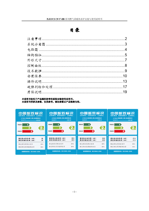
AO史密斯燃气采暖炉JLG26 28 2937-EB电脑板操作说明书
应严格地定期进行检查。 检查时间间隔取决于具体安装情况和使用情况,建议每年由制造商授权的人员
进行一次检查。 采暖装置中的水压在冷却时应在1~1.3bar之间。 控制和安全装置(燃气阀、高温限温器)必须正常工作。 燃烧器和热交换器必须保持清洁。建议用软刷或压缩空气清洁,以免损坏机 器。不要使用化学药品。 清洁文丘里管。 膨胀水箱必须充满空气,压力为1bar。 必须无燃气和水泄漏。 烟道畅通无阻。 燃气流量和压力必须保持在指定值上。
技术数据
型号
采暖系统性能
最大输出功率 最小输出功率
kw kw
生活热水系统 最大输出功率 kw
性能
最小输出功率 kw
输入功率
最大输入功率 kw 最小输入功率 kw
生活热水流量△T=25℃
l/min
生活热水流பைடு நூலகம்△T=35℃
l/min
生活热水最小启动流量
l/min
采暖系统最大运行压力
bar
生活热水系统最大运行压力 bar
燃气连接 燃气供气管必须用硬管,并加装阀门。 须安装足够流量的燃气表具。 从阀门位置开始检测燃气设备的气密性。在试验时,关闭燃气阀,防止超压(最 大压力60mbar)损坏燃气阀。
烟管连接 排烟管末端必须暴露在室外空气中,并保证管道畅通。 必须保证排烟管连接的密封性,同轴烟道内的空气进气和烟气排气不可有混合。 如果有必要可以将连接管切断,但内层管道末端相对外层须凸出20mm。 外界气温低于5℃时,设备会以烟的形式排出水汽。建议不要将末端安装在窗 户下,以免排烟影响视觉。
JLG37-EB 34.5 6 34.5 6 37.5 6.5 19.8 14.13 1.5
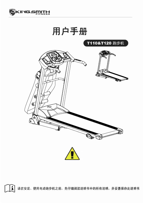
金史密斯跑步机T110、T120中文说明书
1 、“ PROGRAM ” 为 程 式 选 择 键 : 在 待 机 状 态 时 , 按 此 键 可 以 循 环 选 择 从 “ 0.8 ”、 “ P1-P2-P3-P4-P5-P6-P7-P8-P9”的 9 种不同运行程式运行(“0.8”为系统默认运行模 11
式, “P1-P9”为内置程式)。 2、“MODE”为模式选择键:按此键可以循环选择“0.8”、“ H-1”、“ H-2”、“ H-3”(“0.8”
1、手扶在 A 处,脚踢在气压棒的 B 处, 机台会自动往下降。
8
技术参数
外形尺寸(mm) 拆叠尺寸(mm) 跑台尺寸(mm)
1605*640*1320mm 735*640*1530MM
1220*400
使用电源 最大输出功率
输入电流
机台净重
50KG
速度范围
允许使用者最大体 重
100KG
220V 1300W
A
1、使用 5#内六角扳手,用 M8*15 内六 角 平 圆 头 螺 钉 (39) 与 内 锯 齿 锁 紧 垫 圈 (55),将立柱组(B)和电子表架组(A)轻 锁于主车架组上。 注意:一手扶住立柱组,避免让立柱往下 掉。
5
组装说明
组装步骤四:
1、使用带十字扳手,用十字盘头螺钉 M5*8(50)将左
9
可选
1
可选
1
可选
1
可选
1
5#内六角扳手 5mm 1pcs、 带十字扳手 S=13、14、15 1pcs
序号 55 12 50 34 56 81 40 43 36
名称 内锯齿锁紧垫圈 5#内六角扳手 十字盘头螺钉带垫圈
右护罩 标准型弹簧垫圈
弧形垫片 8 内六角平圆头螺钉 内六角平圆头螺钉
Parker 15 40 80CN系列核心无电机中压滤芯说明说明书

Applications• Compressor Lube Oil• Off-line Filter Loops• Machine Tools(Automotive Standard)• Hydrostatic DriveCharge Pumps• Mobile Equipment• Pilot Lines For Servo Controls • Oil Patch Drilling Equipment • Injection MoldingThis partial list of applications for Parker “CN” series filters has a common factor, the need for an economical, medium pressure range filter with excellent fatigue pressure ratings. Prior to the availability of the “CN” filter, applications such as those listed were restricted by limitationsof a spin-on can, or forced into the higher cost range of high pressure filters.The “CN” series fills thisgap, and now with the newly increased fatigue rating from 550 to 800 psi, the applications are expanded.Ecoglass IIIReplacement Elements Ecoglass III represents the merging of high performance filtration technology with environmentally conscious engineering. The Ecoglass III line of replacement elements feature 100% non-metallic construction. The design reduces solid waste and minimizes disposal costs for industry. The non-metallic construction means lightweight elements (60% less weight) for easier servicing.The Ecoglass III elements utilize the same proprietary media design as our Microglass III line of replacement elements.With Ecoglass III, a reusable core is installed into the filter housing and remains in service throughout the life of the assembly.FeaturesPortsSAE, NPT or flange face (80CN) provides mounting flexibility.Diametral (side) SealDust SealProtects head and bowl threads from external contamination buildup.Element AssemblyHigh efficiency (B x >200), high capacity Ecoglass III media with it’s multi-layered design is unequalled in performance.Element Condition IndicatorsAvailable in visual or electrical, with a choice of several power connections (E3 shown).HeadCast aluminum is rugged with small profile for easy mounting.BypassCartridge style bypass has good sealing characteristics and low hysteresis. Choice of two settings to match application needs.BowlAluminum is lightweight and corrosion resistant.Drain Port (optional)Optional drain port allows15CN-1 Element PerformanceFlow vs. Pressure LossResults typical from Multi-pass tests run per test standard ISO 16889 @ 10 gpm to 100 psid terminal - 10 mg/L BUGLRefer to Appendix on pages 264-265 for relationship to test standard ISO 4572.Ef ciency %Ef ciencyBeta Rating 10001000099.999.599.010020020250.095.0Micron Size (c)PSID Capacity123456204060801000 1 2 3 4 5 6 7Capacity (grams)BARP S I D 25201510501.51.00.50.0BARLPM0 10 20 30 40 50 60 70P S I D25201510501.51.00.50.0BARLPM0 10 20 30 40 50 60 7015CN-2 Element PerformanceResults typical from Multi-pass tests run per test standard ISO 16889 @ 15 gpm to 100 psid terminal - 10 mg/L BUGL Refer to Appendix on pages 264-265 for relationship to test standard ISO 4572.Flow vs. Pressure LossEf ciency %Ef ciencyBeta Rating100099.999.599.010020020250.095.0Micron Size (c)PSIDCapacity12345620406080100Capacity (grams)BAR40CN-1 Element PerformanceResults typical from Multi-pass tests run per test standard ISO 16889 @ 15 gpm to 100 psid terminal - 10 mg/L BUGLRefer to Appendix on pages 264-265 for relationship to test standard ISO 4572.Flow vs. Pressure LossPSID Capacity1234560204060801001020 3040Capacity gramsBARPS I D252015105BARLPM1.51.00.50.00 50 100 150 200 250 300 350P S I D2520151050BARLPM1.51.00.50.00 50 100 150 200 250 300 35040CN-2 Element PerformanceResults typical from Multi-pass tests run per test standard ISO 16889 @ 30 gpm to 100 psid terminal - 10 mg/L BUGLRefer to Appendix on pages 264-265 for relationship to test standard ISO 4572.Flow vs. Pressure Loss40CN-3 Element PerformanceResults typical from Multi-pass tests run per test standard ISO 16889 @ 45 gpm to 100 psid terminal - 10 mg/L BUGLRefer to Appendix on pages 264-265 for relationship to test standard ISO 4572.Flow vs. Pressure LossPSID BARCapacity1234562040608020406080100120Capacity (grams)80CN-1 Element PerformanceP S I D2520151050BARLPM1.51.00.50.00 50 100 150 200 250 300 350LPMP S I D 1086420BAR0 50 100 150 200 250 300 350Results typical from Multi-pass tests run per test standard ISO 16889 @ 45 gpm to 100 psid terminal - 10 mg/L BUGLRefer to Appendix on pages 264-265 for relationship to test standard ISO 4572.Flow vs. Pressure LossPSID Capacity123456020406080100Capacity grams020406080100BAREf ciency %Ef ciencyBeta Rating 10001000099.5100200202Micron Size (c)80CN-2 Element PerformanceFlow vs. Pressure LossResults typical from Multi-pass tests run per test standard ISO 16889 @ 70 gpm to 100 psid terminal - 10 mg/L BUGLRefer to Appendix on pages 264-265 for relationship to test standard ISO 4572.PSID Capacity12345602040608010020406080 100 120 140Capacity gramsBARSpecificationsMaximum Allowable OperatingPressure (MAOP):1000 psi (69 bar)Rated Fatigue Pressure:800 psi (55.2 bar)Design Safety Factor: 2.5:1Operating T emperatures:Nitrile: -40°F (-40°C) to 225°F(107°C)Fluorocarbon: -15°F (-26°C) to225°F (107°C)Element Collapse Rating:Standard: 150 psi (10.3 bar)Materials:Head and Bowl: AluminumIndicators: Alum. body, plastic connec-torsBypass: NylonWeights (approximate):Model Single length Double length15CN 2.5 lb. (1.13 kg) 3.5 lb. (1.6 kg)40CN 4.5 lb. (2.00 kg) 5.5 lb. (2.49 kg)80CN 12.4 lb. (5.62 kg) 15.2 lb. (6.89 kg)Element Condition Indicators:Visual 360° green/red auto resetElectrical/Visual5A @ 240VAC, 3A @ 28VDCElectrical-Heavy Duty.25A(resistive) MAX 5 watts12 to 28 VDC & 110 to 175 VACColor code:White (common)Black (normally open)Blue (normally closed)Drawings are for reference only.Contact factory for current version.A. Stop the system’s power unit.B. Relieve any system pressure in the filter line.C. Drain the filter bowl if drain port option is provided.D. Loosen and remove bowl.E. Remove element by pulling downward with a slight twisting motion and discard.F . Check bowl o-ring for damage and replace if necessary.G. Lubricate element o-ring with system fluid andplace on post in filter head.H. Install bowl and tighten to specified torque. 15CN - 15-20 ft. lbs 40CN - 42-50 ft. lbs80CN - 60-70 ft. lbsI. Confirm there are no leaks after powering thesystem.Element Service InstructionsParts ListSelect the desired symbol (in the correct position) to construct a model code.Please note the bolded options reflect standard options with a reduced lead-time. Consult factory on all other lead-time options.How to OrderReplacement Elements (Ecoglass)Global products as identified are offeredworldwide through all Parker locations and utilize a common ordering code.。
Bosch QuietComfort C0228 DLX 80 下流式壁挂炉说明书

H8DNL Product SpecificationsQuietComfortä DLX 80Specifications subject to change without notice.441 11 2317 06 Jan 2010Deluxe 80 Single Stage Downflow Furnace FLEXIBILITY•40″(1016mm) high for ease of installation •Factory shipped for natural gas, with Propane Gas conversion kits available•Dedicated downflow installation•Category I venting•Common ventingSERVICE•Self diagnostics•Entire blower assembly mounted on rails COMFORT•Adjustable time OFF blower delay•24 and 115 VAC humidifier terminal •Electronic air cleaner terminal EFFICIENCY•80% AFUE efficiency range•Single stage gas valve operation•Single stage integrated control •Multispeed, prelubricated PSC motors •Induced draft blower•In−shot burners•Insulated blower cabinet•California NOx approvedQUALITY•RPJ III Aluminized steel heat exchanger•High temperature limit control prevents overheating •Direct ignition with Silicon Nitride ignitor •Flame roll−out sensors standard•Louvered doors•One piece prepainted steel cabinet•Filter rack with permanent filters WARRANTY *• 1 year No Hassle Replacement t limited warranty •20 year heat exchanger limited warranty• 5 year parts limited warranty−With timely registration, an additional 5 year parts limited warranty*Applies to original purchaser/homeowner, some limitationsmay apply. See warranty certificate for complete details.Illustrations and photographs are only representative.Some product models may vary.THIS MODEL80.0DOWNFLOW (NATURAL GAS)Model NumberInput(MBTUH)EfficiencyAFUE +Cooling Capacity@ .5 in wc (125 Pa)Dimensions H x W x D Shipping Wt.Inches Millimeters Lbs KgH8DNL050B12B50,00080% 1.5 − 3.0 TON40 x 151/2 x 291016 x 394 x 73714264 H8DNL075B12B75,00080% 1.5 − 3.0 TON40 x 151/2 x 291016 x 394 x 73714566 H8DNL075F16B75,00080% 2.5 − 4.0 TON40 x 191/8 x 291016 x 486 x 73716073 H8DNL100F14B100,00080% 2.0 − 3.5 TON40 x 191/8 x 291016 x 486 x 73716274 H8DNL100L20B100,00080% 3.5 − 5.0 TON40 x 241/2 x 291016 x 622 x 73717680 H8DNL125L20B125,00080% 3.5 − 5.0 TON40 x 241/2 x 291016 x 622 x 73718484FURNACE SPECIFICATIONS DOWNFLOW POSITIONModel Number NATURAL GASH8DNL050B12075B12075F16100F14100L20125L20INPUT (btuh)50,00075,00075,000100,000100,000125,000 HTG. CAP. (btuh)40,00061,00061,00081,00081,000101,000AFUE % (ICS)80%80%80%80%80%80% TEMP. RISE DEGREES (o F/o C)35-65/19-3635-65/19-3635-65/19-3635-65/19-3630-60/17-3335-65/19-36 VOLTS/PH/HZ115/1/60MIN./MAX. VOLTAGE104/127RATING PLATE AMPS.9.29.012.09.213.513.2 TRANSFORMER (V.A.)40GAS PIPE SIZE - in(mm)1/2 (12.7)FLUE COLLAR SIZE - in(mm) 4 (101.6)COOLING CAP. 3.0 3.0 4.0 3.5 5.0 5.0 DIMENSIONS H x W x D - in(mm)40 x 151/2 x 29 (1016 x 394 x 737)40 x 191/8 x 29(1016 x 486 x 737)40 x 241/2 x 29(1016 x 622 x 737) SHIPPING WEIGHT - Lbs(Kg)142 (64)145 (66)160 (73)162 (73)176 (80)184 (84) (ICS) = Isolated Combustion SystemSpecifications subject to change without notice.2441 11 2317 06Specifications subject to change without notice.3441 11 2317 06BLOWER PERFORMANCE DOWNFLOW POSITIONModel NumberH8DNL050B12 (1)075B12 (1)075F16 (1)100F14 (1)100L20 (1)125L20 (1)BLOWER D x W - in(mm)11 x 8(279 x 203)11 x 8(279 x 203)11 x 10(279 X 254)11 x 10(279 X 254)11 x 10(279 X 254)11 x 10(279 X 254)MOTOR H.P. (TYPE)1/2/PSC 1/3/PSC 1/2/PSC 1/2/PSC 3/4/PSC 3/4/PSC MOTOR SPEEDS444444CIRCULATION AIR BLOWER DATA #H8DNL050B12 (1)E x t e r n a l S t a t i c P r e s s u r e (i n w c /P a )Air Delivery in CFM (L/s)********************(125Pa)ESPTAP LOW MED L MED H HIGH in wc Pa CFM L/s CFM L/s CFM L/s CFM L/s 0.1025702331963454126059515377250.2050663313904427122257714776970.3075624294845399118355814166680.40100567268803379113653613626430.50125510241760359108851313086170.60149461218689325100347312105710.7017441219461729191743311115240.8019936117054325679137310304860.902243101464682216643139484471.00249249118436206529250808381H8DNL075B12 (1)E x t e r n a l S t a t i c P r e s s u r e (i n w c /P a )Air Delivery in CFM (L/s)********************(125Pa)ESPTAP LOW MED L MED H HIGH in wc Pa CFM L/s CFM L/s CFM L/s CFM L/s 0.102563429972834497546013536390.205058827769632896345413376310.307553325265330893644213076170.4010048923160528690542712746010.5012545421455926486140612255780.6014942019851324281038211645490.7017437317647322373734810875130.801993381604252016723179944690.902242551203921856052868844171.00249232109294139529250764361H8DNL075F16 (1)E x t e r n a l S t a t i c P r e s s u r e (i n w c /P a )Air Delivery in CFM (L/s)********************(125Pa)ESPTAP LOW MED L MED H HIGH in wc Pa CFM L/s CFM L/s CFM L/s CFM L/s 0.1025648306900425128560617898440.2050636300913431130761717708350.3075628296916432132862717478240.40100621293897423132462517188110.50125611288889420130961816807930.60149585276869410128360516407740.70174557263843398124058515887490.80199522246809382119256315237190.90224485229748353112252914526851.0024944120868032110414911374648NOTE:(1) Gray area is above maximum temperature rise range.# CFM − Cubic feet per minute airflow.L/s − Liters per secondFilter required for each return −air inlet. Airflow performance includes 1″(25.4mm) washable − 600 FPM (3.0 M/s) max filter media.*See Table for bellyband location on motorH8DNL100F14 (1)E x t e r n a l S t a t i c P r e s s u r e (i n w c /P a )Air Delivery in CFM (L/s)********************(125Pa)ESPTAP LOW MED L MED H HIGH in wc Pa CFM L/s CFM L/s CFM L/s CFM L/s 0.10257563571012478137264718818880.2050671317950448132362418038510.3075585276888419127360117248140.40100538254834394122557816657860.50125491232780368117655516067580.60149439207739349110652215447290.70174387183697329103548814816990.8019932115162929795445013816520.9022425512056126587341212816051.00249210994442107673621132534H8DNL100L20 (1)E x t e r n a l S t a t i c P r e s s u r e (i n w c /P a )Air Delivery in CFM (L/s)********************(125Pa)ESPTAP LOW MED L MED H HIGH in wc Pa CFM L/s CFM L/s CFM L/s CFM L/s 0.10251798849202495522121044237511210.20501754828196092521471013229010810.3075170980718968952081982220510410.4010016627841835866200294521169990.5012516147621774837192290720269560.6014915427281694799183786719439170.7017414706941614762175282718608780.8019913766491521718165077917538270.9022412826051428674154873116457761.002491065503126359614076641508712H8DNL125L20 (1)E x t e r n a l S t a t i c P r e s s u r e (i n w c /P a )Air Delivery in CFM (L/s)********************(125Pa)ESPTAP LOW MED L MED H HIGH in wc PaCFM L/s CFM L/s CFM L/s CFM L/s0.102519369142165102223191094−−−−−−0.20501891892209799022831077−−−−−−0.30751845871202895722461060233411010.401001787843196592721541017225310630.50125172881519028982061973217210250.6014916327701799849195992420629730.7017415367251695800185687619529210.8019914346771593752172881518208590.9022413316281490703160075516877961.002491215573135263814246721537725MODEL NUMBER IDENTIFICATION GUIDEH8DN L0 75B 1 2B#Brand Engineering Rev. Efficiency Denotes minor change8 = Non−Condensing, 80+% Gas Furnace9 = Condensing, 90+% Gas Furnace Marketing Digit Installation Configuration Denotes major change UP = Upflow DN = Downflow Cooling Airflow UH = Upflow/Horizontal HZ = Horizontal08 = 800 CFM16 = 1600 CFMDH = Downflow/Horizontal12 = 1200 CFM20 = 2000 CFMMP = Multiposition, Upflow/Downflow/Horizontal14 = 1400 CFM22 = 2200 CFM Major Design Feature1 = One (Single) Pipe N = Single Stage Cabinet Width2 = Two Pipe P = PVC Vent B = 15.5″ Wide J = 22.8″ WideD = 1 or 2 Pipe T = Two Stage F = 19.1″ Wide L = 24.5″ WideL = Low NOx V = Variable Speed Input (Nominal MBTUH) ACCESSORIESModel Number Description Used With ModelsGAS CONVERSION KITSNAHA001LP 1172958**Natural gas to Propane conversion Kit. Allows field conversion to Propanegas.ALL H8DNL FURNACESNAHA001NG 1172960**Propane to natural gas conversion kit. Allows field conversion to natural gas.(Single Stage)ALL H8DNL FURNACESCOMBUSTIBLE FLOOR SUBBASENAHH001SB Subbase Furnace ONLY: All 151/2″wide furnace models H8DNL050B−075BNAHH002SB Subbase Furnace ONLY: All 191/4″wide furnace models H8DNL075F−100FNAHH010SB Subbase Furnace ONLY: All 241/2″wide furnace models H8DNL100L−125LNAHH004SB Subbase Furnace w/151/2″cased coil H8DNL050B−075BNAHH005SB Subbase Furnace w/191/4″cased coil H8DNL075F−100FNAHH009SB Subbase Furnace w/241/2″cased coil H8DNL100L−125L WARING LABEL REPLACEMENT KITNAHA002WL To replace Warning Labels, Operating Instructions & Wiring Labels on BlowerDoor when neededH8DNL** Fast part numberI nternational Comfort Products, LLCLewisburg, TN 37091 U.S.A.Specifications subject to change without notice.4441 11 2317 06。
- 1、下载文档前请自行甄别文档内容的完整性,平台不提供额外的编辑、内容补充、找答案等附加服务。
- 2、"仅部分预览"的文档,不可在线预览部分如存在完整性等问题,可反馈申请退款(可完整预览的文档不适用该条件!)。
- 3、如文档侵犯您的权益,请联系客服反馈,我们会尽快为您处理(人工客服工作时间:9:00-18:30)。
史密斯80pez9说明书
收据上
我们的政策是促进所有订单的安全交付。
该产品在离开我们的工厂之前已经过彻底检查、包装和质量认证。
可见的损失或损坏
如果提单或快递收据上要求的任何货物损坏或数量不足,请在货运或快递代理人在您的货运单或收据上做出适当的批注之前不要接受它们。
隐瞒损失或损坏
当货件以外观良好的状态交付给您时,如果在运输过程中发生任何丢失或损坏,请在打开包装后立即通知承运人的代理/AO Smith 代表。
关于本手册
本手册是 AO Smith HSE-VAS 热水器操作和定期维护良好实践的指南
在阅读用户手册之前,请勿操作热水器。
请遵循本手册中的说明,以确保人身安全和正确操作本产品。
始终按照所有适用标准安装、操作、检查和维护本产品。
请妥善保管本用户手册,以备日后参考。
公司信息
和创新
您和您所爱之人的安全至关重要。
本手册中有几条与安全相关
的信息,这些信息是在 HSE-VAS 热水器的安装、操作和维护等各个步骤中提供的。
这些消息指出了潜在的危险,并就如何减少任何潜在风险进行了教育。
请务必阅读并遵守本用户手册中提供的所有安全信息。
这是安全警报标志。
此符号提醒您注意可能伤害您和他人的潜在危险。
所有安全信息都将跟随安全警报符号和“危险”或“警告”字样。
危险:表示迫在眉睫的危险情况,如果不避免,将导致死亡或严重伤害。
警告:表示潜在的危险情况,如果不避免,可能会导致死亡或重伤。
注意:表示潜在的危险情况,如果不避免,可能会导致轻微或中度伤害或财产损失。
警告
如果任何部件浸在水下,请勿使用此热水器。
立即联系合格的服务技术人员检查热水器并联系 AO Smith 服务人员更换任何浸水的控制系统部件。
不遵守此说明可能会导致财产损失、重伤或死亡。
重要
这些说明是作为正确安装和操作热水器的指南而编写的。
如果未遵循这些说明,AO 史密斯公司将不承担任何责任。
但是,为了您的安全和避免安装不当造成的损坏,建议热水器必须由合格的维修技术人员安装。
在继续安装说明之前:
检查热水器及其组件是否有损坏。
请勿安装或尝试修理任何损坏的组件。
如果您发现热水器有任何损坏,请联系购买热水器的经销商或致电 AO Smith 客户服务部。
验证卷tag所提供的与热水器手册上标注的一致。
主要特点
Blue Diamond® 玻璃衬里
Blue Diamond® 技术可延长内胆的使用寿命。
内衬比业内任何其他产品都更坚固、更耐腐蚀
玻璃涂层加热元件
元件表面的水垢和沉积物堆积会导致过早失效。
AO 史密斯玻璃涂层有助于防止水垢形成并延长加热元件的使用寿命。
阳极棒
储罐有一个阳极棒,阳极棒具有不锈钢芯,旨在保护储罐免受腐蚀性元素的影响。
阳极棒使用特殊的阴极作用来对抗这些元素,从而延长热水器的使用寿命。
温度控制旋钮
温度控制旋钮允许您将温度设置在 25ºC 至 75ºC 之间的任意
位置。
热断路器
如果水温超过最高预设水平,热断路器将切断电源以确保安全。
多功能安全阀
多功能安全阀设计用于在压力超过预设限值时自动泄压和排水。